Connecting and Wiring the USB Controller Board: LinkMotion USB controller is easy to connect. It offers lots of flexibilities. New 32 bit USB AGNI-IIP controller is available for CNC/Engraving machines and the information is provided first and older 16-bit controller information is provided in the following pages. Advantages of our USB controller board: (1) LinkMotionUSB is the latest addition to the LinkMotion product. The major function of this product is to drive your machines with USB connection to your computer without locking up any computer functions. Your computer and the design programs are free and available to you while the previous job is being processed. (2) The controller is compatible with USB 2.0 specification. It allows transfer of job at a very high speed. It is not compatible with USB 1.1. Do not use any USB 1.1 devices on the computer where you install LinkMotion software. (3) It has a slot for SD card memory. It is used as a job buffer and a spooler. The processing of a job on a machine can go on while the PC can be used for other purposes simultaneously. Approximately 1 minute of machine operation for a job uses 1MB of memory and this controller supports up to 4GB of micro memory. The new version of LinkMotion 3.0 and higher now supports SDHC memory and we have done testing with following ones. Memory chips tested and working with this controller: Sandisk 1 GB, 512 MB, 256 MB, Topram 1gb, PNY 1gb, PNY 4gb SDHC, Samsung 1gb, Transcend 1gb and 'Made in China Generic' 1gb. Memory chips not working with this controller: Kingston 2gb (not SDHC), Kingston 4gb SDHC (4) The USB controller solution is equipped with EMC2 (The Enhanced Machine Control 2) compatible M&G code capability. EMC (the Enhanced Machine Control) is a software system for computer control of machine tools such as milling machines, lathes, engraving machines, torch cutting machines, water jet cutting machines, laser machines, and other multi-axis machines. EMC has been available under Linux and has a very large user base. Now, it is available under Microsoft Windows environment with the same capabilities, precision, and flexibility. Please, visit http://www.linuxcnc.org/ for additional information. (5) The LinkMotion can accept the jobs in the following manner: 2D jobs, 2 1/2D, 3D, 4D, 5D, or 6D jobs created elsewhere using M&G format can be sent to the USB controller using LinkMotion. In other words, the USB controller is totally compatible with M&G codes, one of the most popular command structure for machine control. A list of implemented M&G codes from the complete list of EMC commands is available elsewhere in this document. (6) The board requires 5 VDC with a maximum current requirement of 200 ma. The controller can be configured to receive power from either the USB port of the PC it is connected to or from an independent +5 VDC power supply. The default configuration of the USB controller is to be powered from the USB port of the PC.
Transcript
Connecting and Wiring the USB Controller Board: LinkMotion USB controller is easy to connect. It offers lots of flexibilities. New 32 bit USB AGNI-IIP controller is available for CNC/Engraving machines and the information is provided first and older 16-bit controller information is provided in the following pages. Advantages of our USB controller board:
(1) LinkMotionUSB is the latest addition to the LinkMotion product. The major function of this product is to drive your machines with USB connection to your computer without locking up any computer functions. Your computer and the design programs are free and available to you while the previous job is being processed.
(2) The controller is compatible with USB 2.0 specification. It allows transfer of job at a very high
speed. It is not compatible with USB 1.1. Do not use any USB 1.1 devices on the computer where you install LinkMotion software.
(3) It has a slot for SD card memory. It is used as a job buffer and a spooler. The processing of a job on
a machine can go on while the PC can be used for other purposes simultaneously. Approximately 1 minute of machine operation for a job uses 1MB of memory and this controller supports up to 4GB of micro memory. The new version of LinkMotion 3.0 and higher now supports SDHC memory and we have done testing with following ones.
Memory chips tested and working with this controller: Sandisk 1 GB, 512 MB, 256 MB, Topram 1gb, PNY 1gb, PNY 4gb SDHC, Samsung 1gb, Transcend 1gb and 'Made in China Generic' 1gb.
Memory chips not working with this controller: Kingston 2gb (not SDHC), Kingston 4gb SDHC
(4) The USB controller solution is equipped with EMC2 (The Enhanced Machine Control 2) compatible
M&G code capability. EMC (the Enhanced Machine Control) is a software system for computer control of machine tools such as milling machines, lathes, engraving machines, torch cutting machines, water jet cutting machines, laser machines, and other multi-axis machines. EMC has been available under Linux and has a very large user base. Now, it is available under Microsoft Windows environment with the same capabilities, precision, and flexibility. Please, visit http://www.linuxcnc.org/ for additional information.
(5) The LinkMotion can accept the jobs in the following manner:
2D jobs, 2 1/2D, 3D, 4D, 5D, or 6D jobs created elsewhere using M&G format can be sent to the USB controller using LinkMotion. In other words, the USB controller is totally compatible with M&G codes, one of the most popular command structure for machine control. A list of implemented M&G codes from the complete list of EMC commands is available elsewhere in this document.
(6) The board requires 5 VDC with a maximum current requirement of 200 ma. The controller can be
configured to receive power from either the USB port of the PC it is connected to or from an independent +5 VDC power supply. The default configuration of the USB controller is to be powered from the USB port of the PC.
(7) The board will generate step and direction commands for up to 6 drivers for controlling 6 motors.
The standard explanation is for 3 axes and refers to Additional axis control information if your machine has more then 3 motors.
(8) The USB controller is capable of sensing Home switches, E-Stop, and other inputs.
(9) The USB controller has 6 output connectors. The functions are described later in this document.
(10) The physical size of the controller is about 2.5 in X 2.37 in (64 mm X 60 mm)
(11) It is advisable to mount the controller board in your enclosure such that the USB connector
residing on the controller board and the SD memory card slots are accessible without opening the enclosure.
(12) Optionally, Solustan provides small, standalone enclosure with or without the wiring for the output
connector (DB-25 female) for the convenience of initial testing and/or for an on-going configuration. An optional, external 5 VDC power supply is also available along with the enclosure if required.
(13) New 32 bit AGNI Controller has the capacity for 125,000 steps per second maximum specified
limit. 75,000 steps per second are the maximum specified limit of the older 16 bit USB controller. IMPORTANT WIRING SUGGESTIONS: We have tested it in our labs and we are convinced that the wiring is the weakest link in any machinery. Just like User Interface, the wiring is almost always an afterthought in assembling a machine. We cannot stress more that you should look into the following while wiring your laser machine:
(1) Coming out of the Agni’s connectors, use twisted and shielded pairs to wire the controller to the machine.
(2) Use metal or metalized shells for the cables ending into the connectors. (3) The shield should be grounded only on one side of the cable, preferably on the machine side. Should
not be connected to the controller side. (4) The home or limit switches have two wires, use a twisted pair. (5) All the I/O’s require a ground wire, use a twisted pair. (6) Step motors have a pulse (step) and direction wires, use a twisted pair for each of the axes. (7) PWM signal wire for the spindle power also has a ground wire for return, use a twisted pair. (8) American style, 22 or 20 gauge wires with multi-strands are just fine.
What could happen in an electrically noisy environment? ‐ The controller may sense a noise pulse as reaching home on home wires. If you see the lights on
the limit switches on the Control Pad fluctuating between red and green colors while the machine is not even trying to go home, it is the electrical noise that may be a culprit.
‐ After finishing a job, a good machine does not go back to (0,0) position, steps are added or subtracted during operation due to electrical noise.
‐ If the Spindle power is fluctuating even while cutting a straight line, it may be the noise again.
Warnings for USB Controller board:
1. Plug the LinkMotion controller cable directly into your computer’s USB 2.0 connection. 2. It is important to experiment and determine that the USB controller works with the USB hub or
extension device if the user plans to use such a device. 3. This Laser/Agni controller does not work with USB1.1 connections. If you connect other USB
devices compatible only with 1.1, it may cause problems. All the USB devices including keyboard and mouse in the system shall comply with 2.0 specifications. Always check compatibility for wireless USB devices, if you are using one.
4. Power saver and Screen Saver modes on your computer should be turned off. If these modes are activated, it can cause problems in recognizing the USB connection on a continuous basis.
5. The LinkMotion Agni controller can be configured to power either from the USB connection of the PC or from an external 5 VDC power supply. There is a jumper on the controller board that allows the selection of the power supply for the controller.
6. In case of Laptop computers, AC power unit shall be connected to an AC outlet while operating external USB devices. Sometimes, aggressive power save mode settings under battery operations could activate the disconnection of USB devices. Re-Launching LinkMotion will re-activate the communication in such a situation.
7. Approximately 1 minute of machine operation uses 1MB of SD memory for vector work. This controller supports up to 4GB Memory. If you are using LinkMotion version 3.5 or higher, you could use either SD or SDHC memory cards.
8. It is impossible to test all the available SD Memory cards in the market but we have listed in the following lists ones that work and ones that do not work with this USB controller.
Memory chips tested and working with this controller: Sandisk (1 GB, 512 MB, 256 MB), Topram 1gb, PNY 1gb, PNY 4gb SDHC, Samsung 1gb, Transcend 1gb and 'Made in China Generic' 1gb. Memory chips found not working with this controller: Kingston 2gb (not SDHC) and 4gb SDHC.
9. If serial number of the controller is not recognized by LinkMotion then user will see a message “Unrecognized serial number ______”. Once you click on OK button it will display the second message as “The maximum working area is 1”x1” or 25.4mm x 25.4mm. LinkMotion software can output only 1”x1” jobs at that point. Unauthorized controller bought from unauthorized vendors can cause this kind of problem. Get in touch with Solustan to verify your serial number. Not making proper USB connection with the controller can also display this kind of message and simply disconnecting USB cable form computer end and reconnect and re-launch LinkMotion should resolve it.
10. USB Controller Board Lights: There are three LED lights available to attach to the Agni Controller board – Blue, Amber, and Red. These lights behave in the following manner when connections are made and the board is powered: Blue LED Flashing Slowly – No USB Connection Blue LED Steady – USB powered up and ready Amber LED Flashing Slowly – Waiting for firmware update Amber LED Flashing Fast – No SD (Memory) card Amber LED Steady – USB ready with SD card Red LED – Turns on when the board is powered. It turns off when it makes a proper connection with LinkMotion. It also turns on every time when any machine motion is detected.
Red LED Flashing – If hardware switch for Repeat is installed on the Laser/Agni controller and LinkMotion.INI file is set up properly, then, Red LED starts flashing after a job is processed one time. Pressing the Repeat switch will send the job again to the machine. After a job is processed one time it is ready to repeat the last job using the repeat button on the USB controller as many times as user wishes.
AGNI-IIP 32 bit USB Controller board for CNC
This newest AGNI-IIP controller has plugin Phoenix-type connectors that can be plugged in two different ways compare to earlier AGNI II version that had screw terminals. Two different plugin positions are available such that wires can come out either from the sides or from the top. It is slightly smaller in size and all dimensional details are given on the following page. Wiring information is printed on the board and remaining other technical information is similar to AGNI-II controller that is provided after the AGNI-II pictures. Please follow it properly. Four plastic standoffs may be provided with the controller. They require 0.125” or 3.2mm holes on the mounting surface. The material thickness of the mounting surface should not be greater than 0.062”. If you have thicker material then you should use screws with spacers. The physical dimensions of the controller board are as follows:
1. The size of the controller board is 93.5 mm X 76.2 mm (3.68 in X 3.0 in) 2. There are 4 holes for mounting the controller. The holes are 3 mm in diameter (1/8 inch) 3. Horizontally, the distance between holes is 50.6 mm (2 inches) 4. Vertically, the distance between holes is 40.2 mm (1.57 inches)
3.0”(76.2mm)
1.58”(40.2mm)
3.68” (93.5mm)
1.38” (35mm)
2.5” (64mm)
3.29” (83.4mm)
0.86”(21.8 mm)
1.99”(50.6 mm)
0.62”(15.7 mm)
Specifications: The USB connector protrudes by 5 mm outside the board. The connector for external power supply when connected will extend outward by about 12 mm. (The external +5 VDC connector is NOT required if the jumper is set to accept the power for the controller board from the USB port of a PC.) The Agni controller has a processor running at 96 MHz with 6 axis controls. It comes with an SD memory card holding a capacity of up to 4 GigaBytes of storage. Caution: Controller board is equipped with integrated circuits and high-frequency processors. The components are susceptible to static electricity. We tend to build a static charge on our body while simply walking around in a less than ideal humidity in the environment. It is easy to damage the circuits on the board with a slight touch. It is recommended that a grounding strap on the wrist or other methods to neutralize the build-up of static electricity before handling the controller board. Keep yourself grounded while you continue to work with the controller board.
Connections and configuration of the Agni-IIP controller: 1. Take a look at the above picture of the controller and note that there are only two jumper settings
required for physical connections. Jumper JP1 relates to voltage requirement for the Home (Limit) switches. If the Home switches in your machine only require +5 VDC, you do not need to do anything. The default setting of the jumper JP1 is set to use the internal power. On the other hand, some machines use active home sensing switches that may require higher than +5 VDC for proper operation. In such a case, move the jumper JP1 to the optional power input for home switches. The optional power and Ground input points are at the top left of the board. Connect the switch appropriate power supply here. The voltage of the external power for the Home switches shall not exceed 24 VDC. All the input lines are protected with optoisolators. Also, refer to more detail description for connecting home (limit) switches along with output connections in following pages after the general description. Note the second jumper JP2 situated to the right of the main processor chip in the center of the Agni controller. The Agni controller needs little power. It is possible to power the controller directly from the USB port of the PC. The default setting of the jumper is for the Agni to receive the power from the USB port. If it is necessary to power the controller from external sources, move the jumper JP2 toward the EXT power side. The optional power and Ground inputs are at the bottom right of the controller. Note a removable, 2 pin, green connector. Required voltage is 5 VDC. The voltage of the external power of the Agni controller shall not exceed 6 VDC.
2. Connecting Agni to a machine: 2.1 X, Y, Z, and cylindrical axis motors 2.2 The Agni controller generates Step (sometimes called Pulse) and Direction pulses for each of
the axis. Maximum step rate is 125,000 per second. 2.3 Ground and +5 VDC connections are available along with step and direction commands for
the connections to step motors managing different axis. 2.4 There may not be a need for all four connections. In fact, some step motor drivers require a
step, direction, and either ground or +5 VDC connections. Use whatever is necessary to make connections to the step motor drivers.
2.5 If the machine is equipped with servo motors, please, make sure that the servo motor drivers are capable of accepting step and direction commands.
2.6 The Agni controller is equipped to connect up to 7 outputs and one PWM (pulse width modulation) output for spindle control. Out of the 7 outputs, 4 are connected into the LinkMotion driver settings. If and when required, additional outputs can be made available. Output 1 is for I/O 1 (Can be used for Z axis with solenoid and not motorized) Output 2 is for I/O 2 (Can be used for Z axis with solenoid and not motorized) Output 3 is for I/O 3 Output 4 is for I/O 4 Spindle Control Output 1 and 2 turn on at the beginning of every shape to be cut and turn off at the end of the shape. While output 3 and 4 turn on at the beginning of a job and stay on throughout the job and turn off at the end of the job.
PWM output is available for Spindle control. Please refer to the detail explanation under LinkMotion Control Pad explanation. Invert PWM capability is available from Linkmotion V4.27onwards with a following line in the Linkmotion.INI file under each machine related settings. InvertPWM=0 or 1 The default value is 0(zero) and the user can change it 1 if required. Change is effective after saving the INI file and Re-launch Linkmotion.
2.7 The Home switch connections are self-explanatory. Appropriate settings are available in the LinkMotion software configuration.
2.8 The controller is equipped with soft Control Pad that shows up on the PC screen with many useful features. Please, refer to our main document, the LinkMotion USB for machines. In addition, Solustan provides additional connections for hardware Control Pad that may be required for installing it right on the machine. Please, contact us for protocol information as well as command strings.
2.9 Often overlooked, but the important part is the wiring between the controller and the rest of the machine. This ounce of prevention will go a long way. All the signals going in and out of the controllers are just that, signals. ‐ You do not need thicker than 22 gauge of wire. ‐ Twisted and shielded pairs of wires are the best way to go. ‐ If possible, use three twisted wires in a shield for each of the step motor connections. ‐ If possible, use a twisted pair of wires in a shield for each of the I/O’s, and home
switches. ‐ Use multistrand copper wires. ‐ Connect the shield to a ground on only one side of the wire cluster, preferably on the
machine side. ‐ The laser machine shall be connected to the earth ground, if not already. ‐ When you reduce the effect of the electrical noise on the controller, you are going to have
fewer problems with step accuracy, home sense, and better performance of the system.
Input and Output connections including Home/Limit switches: This description is for AGNI controller hardware. AGNI controller is available with a USB interface (2.0 and higher) and an SD memory card to spool a job coming from USB connection. Here is a picture of the controller:
Note that there are two jumpers on the board JP1 and JP2. 1. The jumper (JP2) to the right of the main processor selects the power required to run the controller from either the USB port of the PC or from external 5 VDC. The total requirement is maximum 200 milliamp when operating and driving all six axes. When the jumper shorts the two pins closest to the USB connector, it takes the power from the USB port.
There are ample ground connections on all the connectors in order to connect signal grounds and completing circuits. 2. The second jumper (JP1) is close to the upper left of the processor as shown in the picture. It determines the availability of the power from either internal 5 VDC or externally supplied power for the home/limit switches.
With the above information in mind, let us take a look at the ways to connect the controller to the outside world. The outside world includes step motor drivers for up to 6 axes, either output including PWM, and the following inputs: - Home/Limit switches for axis X, Y, Z, and C (cylindrical axis). - Cycle start - Probe - E-Stop - Hardware Pause 3. Here is a circuit of all the outputs:
On theAGNI boardACT541
OutputConnectingPoint
OutsideInterfaceInsideCircuit
The controller is equipped with output line drivers IC's ACT541. Each line is capable of sourcing or sinking 20 milliamp. This makes it very nice to directly connect to step motor drivers. An output can connect directly to a solid state relay for controlling the heavy load. The output connections are; Step X, Y, Z, A, B, and C Direction X, Y, Z, A, B, and C Output 1, 2, 3, 4, 5, 6, 7, and PWM Both, ground as well as 5 VDC output pins are made available along with step and direction commands for the step motor drivers. Step motor drivers may require either ground pin or 5 VDC pin for completing the circuit. 4. Here is a circuit of all the inputs:
On theAGNI boardTLP291InsideCircuit
+5VDC2K InputConnectingPoint
OutsideInterface
All the inputs are optically isolated with a 2K resistor to limit the current flowing through the diode. Each of the inputs is equipped with the above circuit. Note that the optoisolator part of the circuit is equipped with its own internal 5 VDC. The outside connections require a signal and a reference ground line. This is totally adequate for either passive Home/Limit switches or active switches that require 5 VDC to operate. Here is the cool part. If the machine is equipped with active Home/Limit switches that require and use higher than 5 VDC, switch the position of jumper JP1. Apply the appropriate voltage to the optional input power switch at the top left pin on the input side of the connections and its associated ground line to the next pin. The same voltage will be applied to the Home/Limit switch circuit with optoisolation for proper operation. Most of the popular active switches work anywhere from 5 VDC to 24 VDC. It is important to note that the Optional Input Voltage for Home/Limit switches shall be limited to 24 VDC. Higher voltage may damage the circuits on the controller board. To further illustrate a possible circuit connection using an active switch, we studied and created a circuit for an Omron EE-SH3 active switch. Here is a possible circuit:
On theAGNI boardTLP291InsideCircuit
Internal+5VDCJumper
2K
ExternalGround
External Voltage up to 24 VDCOutsidethe ControllerInsidethe Controller
ACE
OMRONEE-SH3Active Switch
KGND
JP1
It is important to understand that the AGNI controller board contains sensitive electronic circuits. Proper care must be taken to handle the controller board. It is recommended that the person handling and/or wiring the AGNI controller shall use the ground strap and necessary precautions to keep the static voltage away from the controller. Static electricity can easily damage the controller. E-Stop Switch settings: 1. By default, the LinkMotion software is shipped with E-Stop sensing disabled with an entry in the LinkMotion.INI file. To change the default, search for the line EStop=-1 in the section of the INI file matching the name of the machine you selected when installing. EStop=-1 disables the function. EStop=0 enables the emergency stop function for a normally open E-Stop switch. EStop=1 enables the emergency stop function for a normally closed E-Stop switch. 2. On sensing a signal on the E-Stop line, the controller will halt any motion in progress, display a message on the PC screen, and terminate any profile that is running on the controller. You will need to reset and restart LinkMotion and then prepare and send the job again. Laser machines have many safety switches to make sure that all the doors of the cabinets are closed before the laser power turns ON. All of these safety switches must be connected to the E-Stop pin of the controller. If all switches are normally closed, the switches must be connected in series. Any switch activated will break the circuit and the E-Stop line will become active, stopping laser operations.
If all switches are normally open, the switches need to be connected in parallel. Any switch activated will close the circuit and the E-Stop line will become active, stopping laser operations. 3. There is one jumper on the board. The sensing voltage for the home switches and E-Stop are normally limited to +5 VDC (TTL logic). The controller requires only +5 VDC for its operations. However, home switch sensing may need a voltage higher than +5 VDC. An external voltage is required for switches that are designed to use higher than 5 VDC. In no case, higher than 24 VDC shall be applied. The jumper needs repositioning in addition to applying the external voltage for higher voltage. The jumper position is normally set to the two pins away from the connector 2. For using higher voltages, move the jumper to the pins closest to the DB-25, connector 2. The higher voltage shall be connected to pin 13 on connector 2. The return or the ground for the higher voltage shall be connected to any of the ground lines on connector 2, pin 14-23. 4. There is one jumper on the Agni controller. The jumper is the tallest component of the controller board. When the jumper is in place Agni takes its power from the USB port of the PC. If it is required to provide external power connect it to the +5 VDC power connector on the breakout board, the jumper should be removed before powering the controller. It is very important to make sure that the Agni controller is not powered from both sources: the USB port of a PC and the external +5 VDC power supply.
Older 16 bit USB Controller Pictures of the USB controller board and the enclosure The USB controller board without any connectors showing dimensions
The USB controller board with necessary connectors, USB cable, and SD memory card
The USB controller board in an enclosure (optional item)
The USB controller board +5VDC requirement:
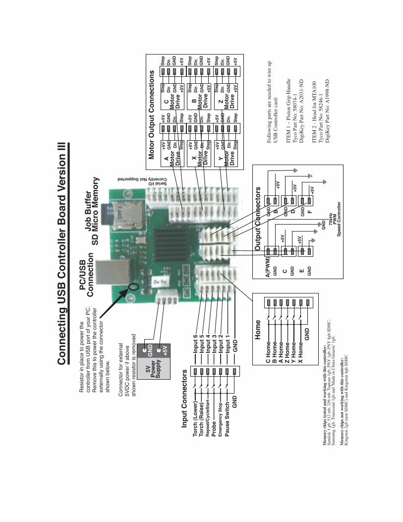
Version II USB controller shipped from 2008. Positions for Motor Output connections for A, X, and Y has been changed compared to version I. Similarly positions for Output connectors B, D, and F also has changed.
Conn
ectin
g US
B Co
ntro
ller B
oard
Ver
sion
III
PC/U
SBCo
nnec
tion
Job
Buffe
rSD
Mic
ro M
emor
y
Inpu
t 6In
put 5
Inpu
t 4In
put 3
Inpu
t 2In
put 1
G
ND
5VPo
wer
Supp
lyG
ND +5V
Paus
e Sw
itch
Torc
h (L
ower
)To
rch
(Rai
se)
Prob
eRe
peat
/Cyc
leSt
art
Emer
genc
y St
op GND
Inpu
t Con
nect
ors
C Ho
me
B Ho
me
A Ho
me
Z Ho
me
Y Ho
me
X Ho
me
GNDHo
me
A(PW
M)
GND C GND
GND
GND
E
75kH
zPW
MSp
eed
Cont
rolle
r
BGND DGND FGND
Out
put C
onne
ctor
s
+5V
+5V+5V
+5V
+5V
Mot
or O
utpu
t Con
nect
ions
Step
Dir.
GND
+5V
Step
Dir.
GND
+5V
Step
Dir.
GND
+5V
StepDir.
GND
+5V
StepDir.
GND
+5V
StepDir.
GND
+5V
AM
otor
Driv
e
XM
otor
Dr
ive
YM
otor
Driv
e
Step
Dir.
GND
+5V
Step
Dir.
GND
+5V
Step
Dir.
GND
+5V
Step
Dir.
GND
+5V
Step
Dir.
GND
+5V
Step
Dir.
GND
+5V
CM
otor
Driv
e
BM
otor
Dr
ive
ZM
otor
Driv
e
Con
nect
or fo
r ext
erna
l 5V
DC
pow
er if
abo
ve
show
n re
sist
or is
rem
oved
Serial I/OCurrently Not Supported
Fo
llo
win
g p
arts
are n
eed
ed
to
wir
e u
p
US
B C
on
tro
ller c
ard
:
IT
EM
1 –
Pis
ton
Grip
Han
dle
Ty
co
Part
No
: 5
80
74
-1
Dig
iKey
Part
No
: A
20
31
-N
D
IT
EM
2 -
Head
fo
r M
TA
10
0
Ty
co
Part
No
: 5
82
46
-1
Dig
iKey
Part
No
: A
19
98
-N
DM
emor
y ch
ips t
este
d an
d w
orki
ng w
ith th
is co
ntro
ller:
Sandis
k 1
gb, 512 m
b, 256 m
b, T
opram
1gb, P
NY
1gb, P
NY
4gb S
DH
C,
Sam
sung 1
gb, T
ranscend 1
gb a
nd 'M
ade i
n C
hin
a G
eneric
' 1gb.
Mem
ory
chip
s not
wor
king
with
this
cont
rolle
r:
Kin
gsto
n 2
gb (
non S
DH
C) a
nd K
ingsto
n 4
gb S
DH
C
Res
isto
r in
plac
e to
pow
er th
e co
ntro
ller f
rom
USB
por
t of y
our P
C.
Rem
ove
this
to p
ower
the
cont
rolle
r ex
tern
ally
usi
ng th
e co
nnec
tor
show
n be
low.
Following parts are needed to wire up USB Controller card: Part No. 1 – Piston Grip Handle Tyco Part No: 58074-1 Digi-Key Part No: A2031-ND Part No. 2 - Head for MTA100 Tyco Part No: 58246-1 Digi-Key Part No: A1998-ND LinkMotion USB controller with 6 axis controls can be configured in the following different ways: 1. X and Y axis with non-motorized control in the Z axis. 2. X, Y, and Z axis motorized controls. 3. X, Y, Z, A, B, and C all 6 axis motorized controls. (A and B axis are not available for LinkMotion USB Laser product) 4. There may be 2 motors in X-axis. In this case, X and A are mirrored axis while Y and Z are configured normally. (not available for LinkMotion USB Laser product) 5. There may be 2 motors in Y-axis. In this case, Y and B are mirrored axis while X and Z are configured normally. (not available for LinkMotion USB Laser product) 6. Some CNC and laser machines have cylindrical axis including engraving machines. C axis can be configured for the cylindrical axis. Standard 3 Axis machines supported by LinkMotion: Position on the Connecting to USB Controller Your Machine and using LinkMotion Motor Output Connection X Connects to X-Axis Driver for Step Motor Output Connection X Connects to X-Axis Driver for Direction Motor Output Connection Y Connects to Y-Axis Driver for Step Motor Output Connection Y Connects to Y-Axis Driver for Direction Motor Output Connection Z Connects to Z-Axis Driver for Step Motor Output Connection Z Connects to Z-Axis Driver for Direction Following are used with USB Controller Serial Number 4600 and above: Contact Solustan if you need to use older Controllers with Serial numbers below 4600 Output B Connects to I/O (4) (I/O signal, turns on and off with the job, Used for Spindle motor
and programmable delay available for LMUSB) Output D Connects to I/O (1) (I/O signal, turns on and off while cutting or engraving a shape
using tool up and tool down LMUSB) Output E Connects to I/O (2) (I/O signal, turns on and off while cutting or engraving a shape
using tool up and tool down LMUSB) Output C Connects to I/O (3) (I/O signal, turns on and off with the job for LMUSB) All the five outputs can be inverted to work properly by changing the value from 0 to 1 or 1 to 0 in the LinkMotion.INI file as explained in the document. (LinkMotion version 2.8 and higher supports home switches of any kind used for the different axis.
LinkMotion version 2.7 and earlier required using all home switches to be the same type either normally open or normally closed and did not support if you use normally open for one axis and normally closed for another axis.) Home Z Connects to Z-Axis home switch Home X Connects to X-Axis home switch Home Y Connects to Y-Axis home switch All Ground lines Ground lines Input 6 Connects to Torch Cutting (Lower) Input 5 Connects to Torch Cutting (Raise) Input 4 Connects to Repeat/CycleStart Input 3 Connects to Probe Input 2 Connects to E-Stop (Declared value 0 (zero) enables normally open switch and value 1 (one) enables normally closed switch from the Linkmotion.INI file. Read the document for more details.) Input 1 Connects to Physical Pause All the outputs including the output lines to the motor drivers are capable of driving the optoisolators if present. In the earlier version of the controller board, the C output was set up to output maximum of 3.3 VDC. All the other outputs are capable of driving 5 VDC. The C output is changed to generate 5 VDC in the newer versions of the controller board. An earlier version of Linkmotion was designed for the logic for the Home switches such that all of the axis needed to have either normally open or normally closed switches. The Home logic did not function properly if some of the switches are normally open and the other switches are normally closed. LinkMotion Version 2.8 onwards supports different type of switches. Refer to Origin setup of Linkmotion for more detail explanations. The ground wire of the external 5 VDC power supply should be connected to the signal ground of the PC connected to the controller via USB cable. USB Controller (with enclosure) to parallel port configuration for machine control: LinkMotion USB comes with our USB controller board. Optionally, USB controller board is housed inside a metal enclosure with USB connector on one side and a DB-25 connector on the other side. The standard configured is shipped as follows: The enclosure has openings for the USB cable connection, a slot to plug in an SD memory card, opening in-between the USB connector and the SD card slot for various LED Indicators for the operation of the USB controller. On the opposite side of the enclosure are two connectors - one for the external power unit and the other is a DB-25 connector to connect the USB controller to the rest of the motion control system. Users may have Solustan's amplifier module connected to a machine using our Virtual Controller solution.
It is possible to simply disconnect the printer port cable from your PC computer and connect the unit to the USB controller enclosure. Please look at the illustration on the following page. Connect the USB cable to your properly configured PC, Install the SD memory card, load the newer version of the LinkMotion USB driver software and you are ready to take advantage of the USB Interface. Please, do refer to additional documents that we have included on the CD under Manual-PDF folder or you can download from our website www.solustan.com/support for a better understanding of the operation of USB controller and its advantages. Creating jobs and compatibility with M&G codes including the compatibility with EMC2 (More Information on our Implementation of M&G codes Is available at http://www.linuxcnc.org/). It is always a good idea and a good practice to turn on the PC first and your driver module after the Windows is loaded and then re-launch LinkMotion. In the same manner, it is always a good Idea to turn off the PC last when you switch off the system. Additional Axis Control available with LinkMotion: Position on the Connecting to USB Controller Your Machine for LinkMotion Motor Step Connection A Connects to A Axis Driver for Step Motor Direction Connection A Connects to A Axis Driver for Direction Motor Step Connection B Connects to B Axis Driver for Step Motor Direction Connection B Connects to B Axis Driver for Direction Normally, we duplicate the same step and direction signals for X and A or Y and B. If the machine is designed with both the motors in the same axis facing the same way (shafts going out in the same direction), you will wire the motors the same way. However, if both the motors in the same axis (both the shafts either facing in or outgoing in opposite direction), you will reverse only one of the windings (A or B) of any one of the motors to create synchronous movement. Please check with motor and the driver manufacturer for more detail information on changing the windings for directional change. LinkMotion driver software has been designed to drive the X or Y axis with two motors. This support is available in the LinkMotion.INI file by changing the value from zero to one. Your LinkMotion.INI file is by the following location: C:\Documents and Settings\Folder with Computer user's name\ Application Data\Solustan\LinkMotion\ LinkMotion.INI Double click on this file and windows NotePad should open it. This is a configuration file and it has the number of machines listed at the beginning and goes down until you find more information for your selected machine name (example) "My Machine-USB". Please find following lines within your machine's data information by scrolling down: XDuplicateA=0 YDuplicateB=0 You can activate by changing XDuplicateA=1 or YDuplicateB=1 depending on how your machine is
designed. Save this file from the File menu after you made the change and close everything. Launch Linkmotion and Highlight one of the values in Linear travel per revolution under Machine setup tab and retype the same number again and click on the Apply button. Now, remember to Re-Launch LinkMotion by exiting from the system's tray at the bottom right and then Re-launch it from the Start button of windows on the bottom left for this to be effective. Motor Step Connection C Connects to C Axis Driver for Step (Cylindrical axis when separate amplifier driver is used) Motor direction Connection C Connects to C Axis Driver for Direction (Cylindrical axis when separate amplifier driver is used) Cylindrical axis support for C axis on the USB controller card requires separate amplifier driver in your hardware. LinkMotion software supports this by changing the value from zero to one in the LinkMotion.INI file as following: UseCAxis=0 (Zero value is declared when X or Y axis becomes cylindrical per your hardware design) UseCAxis=1 (One value is declared when C axis is cylindrical axis per your hardware design) Remember to save this change and Re-Launch LinkMotion for this to be effective as explained earlier.
The standard configuration of DB-25 pin settings: The DB-25 connector on the enclosure is a female connector. You may request male connector. Following are used with USB Controller Serial Numbers 4600 and higher. Contact Solustan if you need to use older Controllers with Serial numbers below 4600 DB-25 pins Signals 1 I/O 2 output switch (I/O turns on and off with the job and Output E on USB controller) 2 X - Step 3 X - Direction 4 Y - Step 5 Y - Direction 6 Z - Step 7 Z - Direction 8 Switching between cylindrical and flat axis (Output C on USB controller)* 9 10 Home switch Input to parallel port- Z axis 11 Future use 12 Home switch Input to parallel port - X axis 13 Home switch Input to parallel port - Y axis 14 I/O 1 output switch (I/O turns on and off with the job and Output D on USB controller) 15 Emergency switch Input to parallel port (configurable) 16 I/O 4, Spindle motor or Air enable (Output B on USB controller) 17 I/O 3 output switch (Output C on USB controller)* 25 Ground line * Typically, when USB controller is used with Solustan’s MaxAmp IV, it was necessary to use pin 8 to switch between cylindrical and flat axis. In newer Amp modules, an additional driver is installed in C output motor location for Cylindrical Axis. This is a standard configuration. Custom configurations are available. The USB outputs B, C, D, and E can individually configure to be default On or Off to suit the needs of your machine. Please, consult Solustan for more information. E-Stop Switch settings: 1. Normally, the LinkMotion software is shipped with E-Stop sensing disabled via the INI file. Search for the line EStop=-1 in the section of the INI file for your machine (Name of the machine you selected when installing). EStop=-1 disables the function. EStop=0 enables emergency stop function for the normally open E-Stop switch. EStop=1 enables emergency stop function for the normally close E-Stop switch. 2. Additionally, you will note an indication on the PC screen and to the right of the Control Pad, when the LinkMotion Control Pad is displayed, a green or red light for the E-Stop configuration. 3. We do not bring out the connections for E-Stop in our current controller enclosure (Upgrade engraving machine kit or USB controller with enclosure option is purchased). There is a slot for a spare DB-25
connector in the back of the controller. It should be simple to bring the E-Stop sensing and ground wire out through the connector. 4. The sensing voltage shall be limited to +5 VDC (TTL logic) when connecting lines to the E-Stop sensing on our controller. Applying higher voltage may damage the controller. 5. On sensing the fault on the E-Stop line, the controller will halt any motion in progress, display a message on the PC screen, terminate any profile that is running in the controller, and will force the user to reset and restart LinkMotion and prepare and send the job again. There is no internal circuit designed to take the power off of the AC to DC power supply. The step motor will still be powered. However, there will be no movement. LinkMotion USB uses EMC2 interpreter with following Supported M and G codes: G0 Rapid linear motion – program X-Y-Z-A-B-C- all 6axis motion commands G1 Linear motion at feed rate G2 Arc at feed rate clockwise G3 Arc at feed rate counterclockwise G4 Dwell G10 Select Coordinate Offset System G17, G18, G19 Select Plane G20 for inch, G21 for mm works with LinkMotion. Some G-Code generating programs use G70, G71 and user should replace these with G20 for inches and G21 for mm. G40, G41, G42 Cutter Compensation (requires pre-defined tool table file) G43, G49 Tool Length Offsets (requires pre-defined tool table file) G53 Position Move without regard to current Coordinate Offset G54, G55, G56, G57, G58, G59, G59.1, G59.2, G59.3 Set Coordinate Offset (requires coordinate parameter file) G61, G61.1, G64 Set Path Control Mode (Control radius at corners like P0.004) It is important to have P in front of the value. G80 Cancel Modal Motion G81-Drilling, G82-Drilling with Dwell, G83-Peck Drilling / Canned Cycles G90-Absolute mode, G91-Incremental mode G92, G92.1, G92.3 Coordinate System Offsets G93, G94 Set Feed Rate Mode – G94 to start units per minute mode. G93 to start inverse time mode. G98, G99 Canned Cycle Return Level M1 – Stop running program temporarily (not sure) M2 or M30 to end the Program. M3-Spindle start Clockwise, M4-Spindle start Anticlockwise, M5-Stop Spindle / Spindle Control (Do not include S commands for spindle speed) M7 and M8-Coolant on, M9-Coolant Off / Coolant Control M6 – Tool Change command – T(X) M62 Turn on digital Output synched with motion, M63 Turn off digital output synched with motion M64 Turn on digital output immediately, M65 Turn off digital output immediately. If your software generates F commands for feed rate it should always have proper number values like F2.0 for job feed rate. If you have 0.00 value or no value after F it will not process your file. You also need to have the end of the file command with either M02 or M30. Files will not be processed if the end of the file command is missing.
The process requirement for beginning will be as follows:
1. The user will set the tool at X=0, Y=0, and Z=0. Typically, the user may bring the tool to lower left of the machine and bring the tool down to where it touches the top of the surface. Also, the material may also be set to the lower left of the machine.
2. If there is a jig set up, the user may bring the tool to one of the corners of the material and bring the tool to the top surface of the material. This will be 0, 0, 0.
3. The CAM program shall have the facility to declare a very first move command to be a tool lift distance defined by the user.
4. The processing will start at this point. Including spindle on, turning on of the I/O’s, G rapids, and the rest of the job.
5. If the CAM program does not have the facility to lift the Z axis at the beginning of the job, the user will be required to edit the file and insert appropriate tool lift command.
6. Assuming X axis to be the axis from left to right as the user faces the machine, X-axis moving right is a positive number and X-axis moving left is a negative number.
7. Assuming Y axis to be the axis from front to back as the user faces the machine, Y-axis moving away from the user is a positive number and Y-axis moving toward the user is a negative number.
8. For the Z axis, Z axis moving up is a positive number and Y-axis moving down is a negative number.


![화학반응의 증거를 찾아보자kcsnet.or.kr/main/k_chemedu/pdffile/38_02/3802026.pdf · [심화자료] 1. 강황(심황, Turmeric Oleoresin) 비타르계 천연 색소로 심황의](https://static.documents.pub/doc/80x56/5f5f48d6f3130a52c21a9047/e-ee-e-eoe-1-e-turmeric.jpg)


