43 Cisco Systems, Inc. www.cisco.com Connecting the Router to Power This section describes how to connect the Cisco 1120 Connected Grid Router to AC and DC power source These topics are discussed: Before You Begin, page 43 AC Power Connection Information, page 45 Connect to AC Power, page 49 Connect to DC Power, page 50 Power Cycling the Router, page 51 Before You Begin Before you connect power to the router, read these topics: Verify Router Hardware Readiness, page 43 Tools and Materials You Supply, page 43 EMC Class A Notices and Warnings (US and Canada), page 44 Safety Information, page 44 Verify Router Hardware Readiness Before connecting the router to power, verify the following: The unit is grounded as described in Mounting the Router, page 33. The SD flash memory module is installed correctly as described in Using the SD Flash Memory Module, page 77. Tools and Materials You Supply You must provide the following tools and materials to connect the router to AC power or optional DC power: Note: For the AC power connector, a 5-way screw terminal printed circuit board plug connector manufactured by Phoenix Contact (part number 1913604) is supplied. Note: For the DC power connector, a 2-way screw terminal printed circuit board plug connector manufactured by Phoenix Contact (part number 1912184) is supplied. Wire-stripping tool Flat-blade screwdriver
Transcript
Connecting the Router to PowerThis section describes how to connect the Cisco 1120 Connected Grid Router to AC and DC power source
These topics are discussed:
Before You Begin, page 43
AC Power Connection Information, page 45
Connect to AC Power, page 49
Connect to DC Power, page 50
Power Cycling the Router, page 51
Before You BeginBefore you connect power to the router, read these topics:
Verify Router Hardware Readiness, page 43
Tools and Materials You Supply, page 43
EMC Class A Notices and Warnings (US and Canada), page 44
Safety Information, page 44
Verify Router Hardware ReadinessBefore connecting the router to power, verify the following:
The unit is grounded as described in Mounting the Router, page 33.
The SD flash memory module is installed correctly as described in Using the SD Flash Memory Module, page 77.
Tools and Materials You SupplyYou must provide the following tools and materials to connect the router to AC power or optional DC power:
Note: For the AC power connector, a 5-way screw terminal printed circuit board plug connector manufactured by Phoenix Contact (part number 1913604) is supplied.
Note: For the DC power connector, a 2-way screw terminal printed circuit board plug connector manufactured by Phoenix Contact (part number 1912184) is supplied.
Wire-stripping tool
Flat-blade screwdriver
43
Cisco Systems, Inc. www.cisco.com
AC power cable that meets the following requirements:
— Wiring compatible with the power supply used at your site: single-phase or three-phase, rated 10A minimum
— Plug that is compatible with the power source used at your site: single-phase or three-phase.
— Correct length for your installation
DC power cable that meets the following requirements:
— The length and gauge of the DC power cable must be selected such that the voltage supplied to the terminals of the router does not drop below 10.6VDC, which is the minimum recommended operating voltage. See the Power Specifications section in the Router Hardware Description chapter.
— The maximum input current at 9VDC input will be less than 7A and the wire size must be selected by considering the installation DC operating voltage. DC input on the router accommodates a 12AWG to 18AWG wire size.
— Please consult your Cisco reseller, partner, or sales representative for unusual installation requirements of greater than 30 feet of cabling.
EMC Class A Notices and Warnings (US and Canada)Tip: For a complete listing of all EMC Class A Notices and Warnings, refer to following document:
Regulatory Compliance and Safety Information for the Cisco 1000 Series Connected Grid Routers
Class A Notice for FCC, page 44
Class A Notice for Canada, page 44
Class A Notice for FCCModifying the equipment without Cisco's authorization may result in the equipment no longer complying with FCC requirements for Class A digital devices. In that event, your right to use the equipment may be limited by FCC regulations, and you may be required to correct any interference to radio or television communications at your own expense.
This equipment has been tested and found to comply with the limits for a Class A digital device, pursuant to Part 15 of the FCC Rules. These limits are designed to provide reasonable protection against harmful interference when the equipment is operated in a commercial environment. This equipment generates, uses, and can radiate radio frequency energy and, if not installed and used in accordance with the instruction manual, may cause harmful interference to radio communications. Operation of this equipment in a residential area is likely to cause harmful interference in which case users will be required to correct the interference at their own expense.
Changes or modifications not expressly approved by the party responsible for compliance could void the user's authority to operate the equipment.
Class A Notice for CanadaThis Class A digital apparatus complies with Canadian ICES-003.
Cet appareil numérique de la classe A est conforme à la norme NMB-003 du Canada.
This device complies with Industry Canada (IC) license-exempt RSS standard(s). Operation is subject to the following two conditions: (1) this device may not cause interference, and (2) this device must accept any interference, including interference that may cause undesired operation of the device.
Safety InformationWhen connecting the router to AC power, you must ensure that the following conditions are met:
AC power is available at the installation location.
AC power can be readily and conveniently removed from the router. The power should not be removed by disconnecting the AC power connector on the unit.
Warning: The plug-socket combination must be accessible at all times, because it serves as the main disconnecting device. Statement 1019
Warning: Only trained and qualified personnel should be allowed to install, replace, or service this equipment. Statement 1030
Warning: Installation of the equipment must comply with local and national electrical codes. Statement 1074
Warning: Before connecting or disconnecting the power cord, you must remove AC power from the power cord using a suitable service disconnect.
When you install the unit outdoors, or in a wet or damp location, the AC branch circuit that powers the unit should have ground fault protection (GFCI), as required by Article 210 of the NEC.
Ensure that the user-supplied AC power plug is certified for outdoor use and has a minimum rating, such as Interpower 84131251 or Hubbell HBL316P6W (IEC/EN60309 pin-and-sleeve type connectors).
If the power cord goes through a metal cover, a bushing should be installed to prevent fraying of the cord. When using a strain relief bushing, follow these recommendations:
— Use properly sized parts that are suitable for outdoor installation
— Use bushings that are safety certified
AC Power Connection InformationThis section provides information you need to connect the router to AC power and includes the following topics:
Router Power Source Input Terminals, page 45
Electrical Wire Color Codes, page 46
Terminal Blocks and Mating Connectors for Power Input Wiring, page 47
Router Power Source Input TerminalsThe Cisco CGR 1120 Router has two sets of terminals for power input (see Figure 1 on page 46):
A set of five terminals for AC-input power source wires
A set of two terminals for DC-input power source wires
45
Figure 1 Router Power Source Input Terminals
Figure 1 on page 46 shows the label for each terminal.
Electrical Wire Color CodesThis section provides general information about the standard wire coloring used for AC and DC power connections. Use these colors as a guide when wiring the terminal block as part of the AC power and DC power connection procedure.
Caution: Verify power wire color information for your installation site with a qualified electrician before making any power connections to the router.
Table 1 Power Input Terminals
Item
Terminal Type Description
1 AC-Input Power Source Terminals
Ground terminal
To provide a protected earth ground, terminate either a green/yellow or green wire (region-specific) from the AC power cable on the external screw on the left side of the router.
See Table 2 on page 47 for details on wiring colors by region
N Neutral wire terminal
L3 Line terminal
L2 Line terminal
L1 Line terminal
2 DC-Input Power Source Terminals
– Negative
+ Positive
3022
22
1 2
46
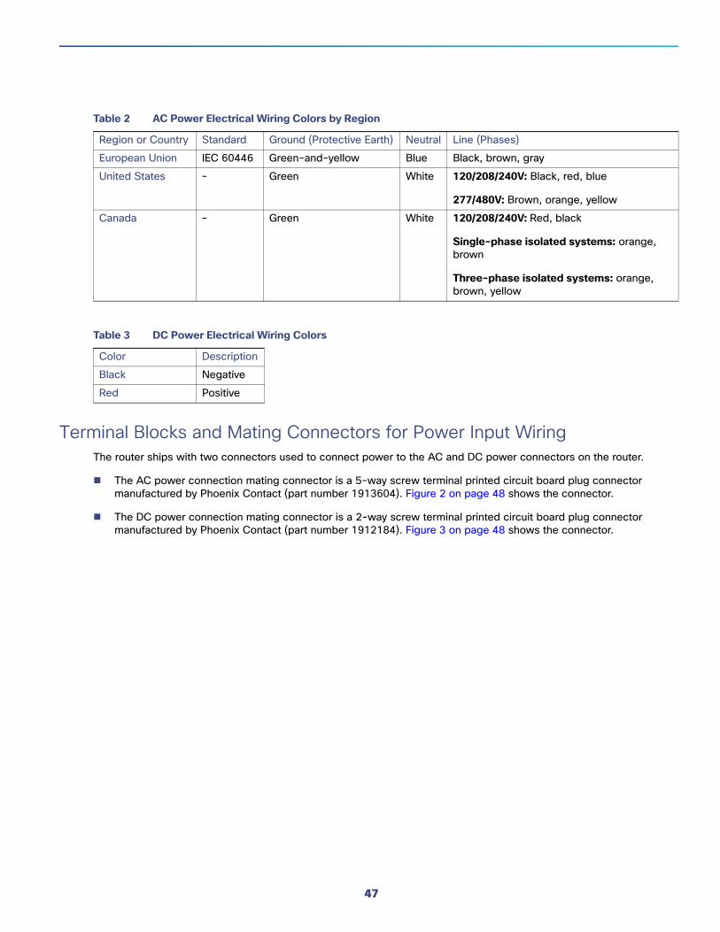
Terminal Blocks and Mating Connectors for Power Input WiringThe router ships with two connectors used to connect power to the AC and DC power connectors on the router.
The AC power connection mating connector is a 5-way screw terminal printed circuit board plug connector manufactured by Phoenix Contact (part number 1913604). Figure 2 on page 48 shows the connector.
The DC power connection mating connector is a 2-way screw terminal printed circuit board plug connector manufactured by Phoenix Contact (part number 1912184). Figure 3 on page 48 shows the connector.
Table 2 AC Power Electrical Wiring Colors by Region
Region or Country Standard Ground (Protective Earth) Neutral Line (Phases)
European Union IEC 60446 Green-and-yellow Blue Black, brown, gray
United States – Green White 120/208/240V: Black, red, blue
1 Captive screws, for connecting terminal block to mating connector on the router 2
2 Terminal openings for inserting AC-input source wires 5
3 Screws for tightening wires into terminal openings 5
Item Description Quantity
1 Terminal openings for inserting DC-input source wires 2
2 Captive screws, for connecting terminal block to mating connector on the router 2
3 Screws for tightening wires into terminal openings 2
3022
18
1 2
3
3022
19
1 2
3
48
Figure 4 Terminal Block Mating Connectors Connected to Router Chassis
Connect to AC PowerThis section describes how to make two the following types of AC power connections to the router:
Single-phase AC
Three-phase AC
Note: The AC power connection mating connector shipped with the router is a 5-way screw terminal printed circuit board plug connector manufactured by Phoenix Contact (part number 1913604).
To connect the router to AC power, follow these steps:
Note: The router will power on as soon as it is connected to an AC power source. You are not required to press a power button to power on the router.
Caution: When connecting the router AC power connector, always connect the router end of the cable first. When removing the AC power connector, always disconnect the router end of the cable last.
1. Turn off power to the AC power source at the designated circuits.
2. Use a wire-stripping tool to strip each of the wires from the AC-input power source. Expose the wire to the appropriate length for the terminal block, about 0.25 inches.
3. Insert the wires into the AC power connector terminals described in Figure 1 on page 46 and Table 1 on page 46.
Insert wires that correspond to your installation (three-phase or single-phase), as shown in Figure 5 on page 50.
3022
21
49
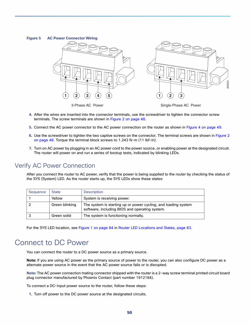
Figure 5 AC Power Connector Wiring
4. After the wires are inserted into the connector terminals, use the screwdriver to tighten the connector screw terminals. The screw terminals are shown in Figure 2 on page 48.
5. Connect the AC power connector to the AC power connection on the router as shown in Figure 4 on page 49.
6. Use the screwdriver to tighten the two captive screws on the connector. The terminal screws are shown in Figure 2 on page 48. Torque the terminal block screws to 1.243 N-m (11 lbf-in).
7. Turn on AC power by plugging in an AC power cord to the power source, or enabling power at the designated circuit. The router will power on and run a series of bootup tests, indicated by blinking LEDs.
Verify AC Power ConnectionAfter you connect the router to AC power, verify that the power is being supplied to the router by checking the status of the SYS (System) LED. As the router starts up, the SYS LEDs show these states:
For the SYS LED location, see Figure 1 on page 84 in Router LED Locations and States, page 83.
Connect to DC PowerYou can connect the router to a DC power source as a primary source.
Note: If you are using AC power as the primary source of power to the router, you can also configure DC power as a alternate power source in the event that the AC power source fails or is disrupted.
Note: The AC power connection mating connector shipped with the router is a 2-way screw terminal printed circuit board plug connector manufactured by Phoenix Contact (part number 1912184).
To connect a DC-input power source to the router, follow these steps:
1. Turn off power to the DC power source at the designated circuits.
3-Phase AC Power Single-Phase AC Power
3022
23
1 2 3 1 2 34 5
Sequence State Description
1 Yellow System is receiving power.
2 Green blinking The system is starting up or power cycling, and loading system software, including BIOS and operating system.
3 Green solid The system is functioning normally.
50
2. Using a wire-stripping tool to strip both of the wires from the DC-input power source. Expose the wire to the appropriate length for the DC power connector, about 0.25 inches.
3. Insert the wires into the DC power connector terminals described in Figure 1 on page 46 and Table 1 on page 46.
Note: When you insert the wires in the terminals as shown in Figure 6 on page 51, ensure that the polarity matches: negative-to-negative and positive-to-positive).
Figure 6 DC Power Connector Terminals
4. Use the screwdriver to tighten the two captive screws on the connector. The terminal screws are shown in Figure 6 on page 51. Torque the terminal block screws to 1.243 N-m (11 lbf-in).
5. Connect the DC power connector to the DC power connection on the router as shown in Figure 4 on page 49.
6. Use the screwdriver to tighten the two captive screws on the terminal block to the mating connector. The terminal screws are shown in Figure 2 on page 48. Torque the terminal block screws to 1.243 N-m (11 lbf-in).
7. Enable DC power by plugging in the DC power supply cord to the power source, or by enabling power at the designated circuit.
Power Cycling the RouterThere are two reset buttons on the router cable panel, which can be used to power cycle the router and to reset the router system software to the default configuration. Use the reset buttons as described in this section.
Caution: When you use the CONFIG Reset button to restore the router to the factory default software configuration, the current software configuration is permanently deleted from the router.
Accessing the ButtonsYou must provide a pin, paper clip, or other thin metal tool to access and press these buttons.
3022
20
51
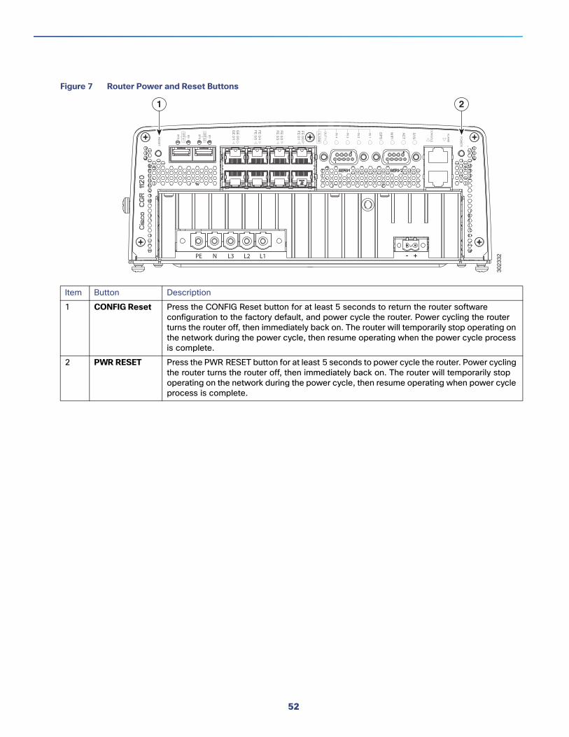
Figure 7 Router Power and Reset Buttons
Item Button Description
1 CONFIG Reset Press the CONFIG Reset button for at least 5 seconds to return the router software configuration to the factory default, and power cycle the router. Power cycling the router turns the router off, then immediately back on. The router will temporarily stop operating on the network during the power cycle, then resume operating when the power cycle process is complete.
2 PWR RESET Press the PWR RESET button for at least 5 seconds to power cycle the router. Power cycling the router turns the router off, then immediately back on. The router will temporarily stop operating on the network during the power cycle, then resume operating when power cycle process is complete.


![TV - Philips...POWER TV ANTENNA Satellite Coax [SAT] COMMON INTERFACE CAM SATELLITE Coax 43” POWER 49”/55” Set top box/Multimedia Player(FHD source) Network - Wireless ROUTER](https://static.documents.pub/doc/80x56/5f06a0a17e708231d418ef5d/tv-philips-power-tv-antenna-satellite-coax-sat-common-interface-cam-satellite.jpg)


