NCHRP Project 12-95 Connection Details of Adjacent Precast Box Beam Bridges Interim Report I 2/21/2014 TRANSPORTATION RESEARCH BOARD NAS-NRC LIMITED USE DOCUMENT This Work Plan is furnished only for review by members of the NCHRP project panel and is regarded as fully privileged. Dissemination of information included herein must be approved by the NCHRP.
Interim Report I 2/21/2014 TRANSPORTATION RESEARCH BOARD NAS-NRC LIMITED USE DOCUMENT This Work Plan is furnished only for review by members of the NCHRP project panel and is regarded as fully privileged. Dissemination of information included herein must be approved by the NCHRP.
i
Table of Contents
Table of Contents ........................................................................................................................... i
List of Figures ............................................................................................................................... iii
List of Tables ................................................................................................................................ iv
5.1.2 Collection of Material Properties and Selection of the Joint Material and Keyway Preparation ............................................................................................................. 38
5.1.3 Crack Development and Resistance Investigation using Small-Scale Testing and FE Simulations .............................................................................................................. 40
5.1.4 Investigation of Cracking in Bridges with Variable Attributes ............................... 45
5.1.5 Influence of Shear Key Geometry on Keyway Behavior ......................................... 47
5.1.6 Cracking and Resistance Investigation using Full-Scale Testing and FE Simulations .............................................................................................................. 50
5.1.7 Parametric study ..................................................................................................... 52
5.2 Specification Development ............................................................................................... 53
6. Data Archiving and Sharing Plan ......................................................................................... 55
6.1 Background and Significance .......................................................................................... 55
6.2 Expected Data Formats .................................................................................................... 55
6.3 Description of Data Archiving and Quality Assurance Plan .......................................... 55
6.4 Description of Data Sharing Plan .................................................................................... 56
6.5 Schedule for Data Archiving and Public Release of Data .............................................. 56
6.6 Milestones for the Implementation of the Plan ............................................................... 56
ii
6.7 Resources and Budget ...................................................................................................... 56
Appendix B - Focus Group......................................................................................................... 70
iii
List of Figures
Figure 1 Basic Keyway Geometries ............................................................................................... 4 Figure 2 States Frequently using Adjacent Box Beam Bridges ...................................................... 6 Figure 3 Basic Shearkey Shapes ................................................................................................... 22 Figure 4 Keyway Geometries for PCI and TxDOT Style-Box Girder Bridges ............................ 23 Figure 5 Typical Michigan Keyway Geometry and Post-tensioning ............................................ 24 Figure 6 Common shearkey locations........................................................................................... 25 Figure 7 Common Bearing Pad Details ........................................................................................ 26 Figure 8 Connection Details Proposed by Hanna et al. [2011]..................................................... 28 Figure 9 Connection Details Proposed by Hansen et al. [2012] ................................................... 29 Figure 10 Typical Box Beam Cross-section ................................................................................. 38 Figure 11 Small Scale Specimen Keyway Geometries (all units are inches) ............................... 40 Figure 12 Basic Configuration for Step B Testing ....................................................................... 41 Figure 13 Small Scale Specimen Test Setup During Curing ........................................................ 42 Figure 14 Small Scale Specimen Test Setup during Post-tensioning ........................................... 43 Figure 15 Shear Key Geometries for Medium Scale Specimens .................................................. 48 Figure 16 Medium Scale Specimen Test Setup ............................................................................ 49 Figure 17 Setup for Large Scale Testing ...................................................................................... 52
iv
List of Tables
Table 1 Structural Design and Details [Russell 2009] .................................................................. 15 Table 2 Specifications and Construction Practices [Russell 2009] .............................................. 16 Table 3 Recommended Practices [Russell 2009] .......................................................................... 17 Table 4 Design and Construction Attributes ................................................................................. 31 Table 5 Summary of FE Analysis ................................................................................................. 33 Table 6 Summary of Laboratory Testing ...................................................................................... 34
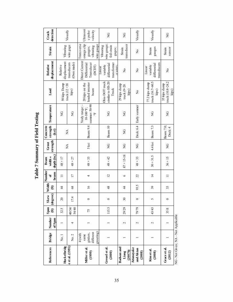
............................................................................................... 35 Table 7 Summary of Field TestingTable 8 Initial Joint Material Property Testing ............................................................................. 39 Table 9 Keyway Interface Preparation Testing ............................................................................ 39 Table 10 Time Dependent Material Property Testing .................................................................. 39 Table 11 Small Scale Specimens .................................................................................................. 41 Table 12 Step D Parametric Study Matrix .................................................................................... 47
1
1. Introduction
This report serves as Interim Report 1 for NCHRP Project 12-95 “Connection Details of Adjacent Precast Box Beam Bridges”. This report documents activities completed during Phase I of the project including: information collection (project survey, industry survey, focus group, and literature review), development of proposed analytical and testing programs to investigate cracking in the longitudinal joints between adjacent beams, and the establishment of a data archiving and sharing plan. Given the scope of the analytical and experimental programs, the information of principal interest in Interim Report 1 is the information collection and the proposed methodologies for the remainder of the project.
2
2. Project Survey
2.1 Summary of Reponses
A web-based survey was distributed to the U.S. Departments of Transportation to gather information about their experience with the performance of adjacent precast box girders and to collect specific information on details and specifications used by these owners. Twenty eight responses were received of which twenty indicated that they had experience with precast box girder bridges.
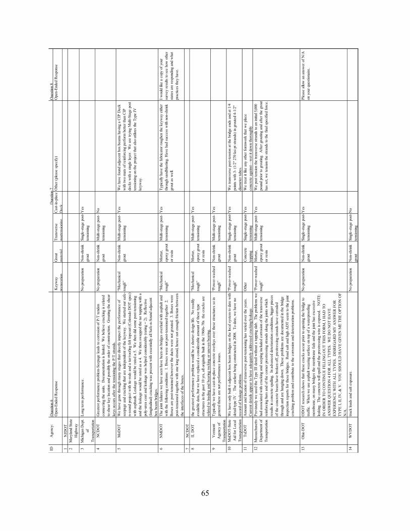
In addition to contact information, agencies were asked to identify the type of keyway they used, to rate the cracking and leaking performance of the joint between box girders, to describe their greatest performance problem, and, based on their experience, to identify the best keyway construction practices (keyway preparation, grout material, transverse post-tensioning, and cast-in-place deck). The questionnaire used in the survey is given in Appendix A - Project Survey to State DOTs. State-by-state responses are presented in Appendix A - Project Survey to State DOTs. A few states provided links to plan drawings that illustrate some of the details they use for box girder connections, as shown in Appendix A - Project Survey to State DOTs. A summary of the responses is given below.
Typical keyway detail usage (see Figure 1):
Ten states use keyway detail Type III with some variations in dimensions and with some reporting problems with performance.
No states use keyway details Type I and II, five use keyway detail Type IV, and one uses keyway detail Type V.
Cracking and leaking performance rating for keyway detail Types I, II, III, IV and V (1 is no leakage, 5 is major cracking and excessive leakage):
None of the details performed to the owner’s expectations. Type IV and V (the best rated) averaged a score of about 2.5; Type I, II, III averaged
around 3.5 (note that no states reported actually using Types I or II. Thus, these scores may be based upon prior/older details or speculated performance).
Performance related to cracking and leaking:
Three states reported that they had no particular performance issues (Vermont, Minnesota, and Texas). Follow-up phone discussions were conducted with these three states to gain more insight. A brief summary for each is as follows:
o Vermont Uses a 5 in., double reinforced, composite, cast-in-place structural deck
and attributes the lack of performance issues to its usage. Bridges have been in-service for approximately 15 years. Recently decreased the spacing of post-tensioning locations to
approximately 20 ft. o Texas
Uses a 5-in., double reinforced, composite, cast-in-place structural deck and what was described as a “relatively substantial keyway” and attributes the lack of performance issues to these details.
Basically see no water intrusion after changing to their current concepts.
3
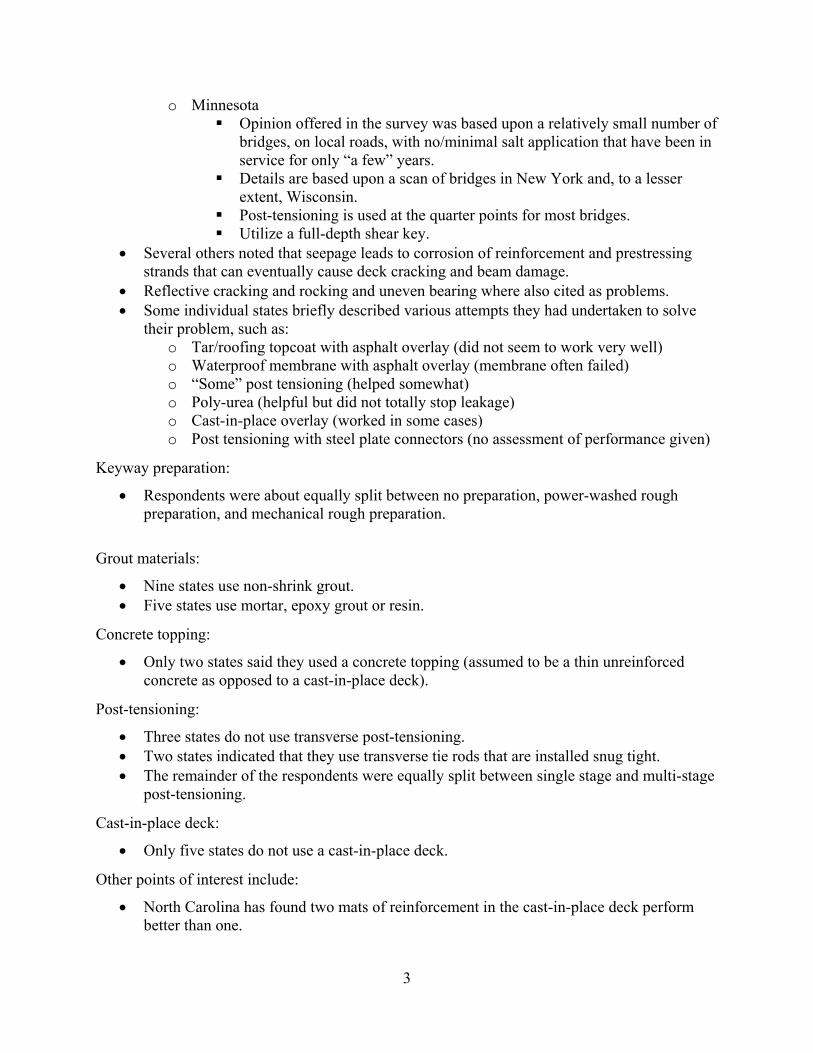
o Minnesota Opinion offered in the survey was based upon a relatively small number of
bridges, on local roads, with no/minimal salt application that have been in service for only “a few” years.
Details are based upon a scan of bridges in New York and, to a lesser extent, Wisconsin.
Post-tensioning is used at the quarter points for most bridges. Utilize a full-depth shear key.
Several others noted that seepage leads to corrosion of reinforcement and prestressing strands that can eventually cause deck cracking and beam damage.
Reflective cracking and rocking and uneven bearing where also cited as problems. Some individual states briefly described various attempts they had undertaken to solve
their problem, such as: o Tar/roofing topcoat with asphalt overlay (did not seem to work very well) o Waterproof membrane with asphalt overlay (membrane often failed) o “Some” post tensioning (helped somewhat) o Poly-urea (helpful but did not totally stop leakage) o Cast-in-place overlay (worked in some cases) o Post tensioning with steel plate connectors (no assessment of performance given)
Keyway preparation:
Respondents were about equally split between no preparation, power-washed rough preparation, and mechanical rough preparation.
Grout materials:
Nine states use non-shrink grout. Five states use mortar, epoxy grout or resin.
Concrete topping:
Only two states said they used a concrete topping (assumed to be a thin unreinforced concrete as opposed to a cast-in-place deck).
Post-tensioning:
Three states do not use transverse post-tensioning. Two states indicated that they use transverse tie rods that are installed snug tight. The remainder of the respondents were equally split between single stage and multi-stage
post-tensioning.
Cast-in-place deck:
Only five states do not use a cast-in-place deck.
Other points of interest include:
North Carolina has found two mats of reinforcement in the cast-in-place deck perform better than one.
4
Minnesota places post-tensioning at the ends of the beams and at the quarter points (grouted tubes).
Massachusetts does an initial post-tensioning of 5,000 pounds, then grouts, then performs final post-tensioning of the system.
Wisconsin experimented with a single layer of reinforcement in decks. There is an ongoing research program at Western Michigan University.
Figure 1 Basic Keyway Geometries
2.2 Best Practices
Of the responses received from the survey, the following summary seems to be a consensus of current best practices (i.e., what works best and what doesn’t seem to work very well). The items identified with an asterisk (*) were also listed as practices that affect the likelihood of longitudinal cracking in box girder bridges in the NCHRP Synthesis report [Russell 2009].
What works: Type IV or V full depth keyway* Cast-in-place deck* Post tensioned system* Keyway roughening* Non-shrink grout or mortar*
Narrow longitudinal joint
Wide and deep longitudinal joint (Cast-in-place concrete)
Type IV Type V
Type I Type II Type III
5
What doesn’t work: No keyway prep* Waterproof membrane No cast-in-place deck* Asphalt overlay* Type I, II and III keyway*
Inconclusive: Power-washed vs. mechanical rough keyway preparation Single stage vs. multi-stage post tensioning Required post tensioning amount and location Single layer vs. two layer deck reinforcement Steel plate shear connectors Epoxy grout
2.3 Information for States Using Large Numbers of Adjacent Box Beam Bridges
Based on the National Bridge Inventory (NBI) data from 2002-2012, the ten states having the most adjacent box beam bridges are shown in Figure 2(a) and the ten states having constructed the most adjacent box beam bridges in the last ten years are shown in Figure 2(b). From these figures one can clearly see that those that have had high numbers of adjacent box beam bridges in the past seem to continue to build them now. Also of interest is that the majority of these bridges tend to be in locations that experience snow (and thus likely have deicing material application). For easy reference the specific survey responses for the states in these top ten lists that responded to the survey are given in the following pages. Some interesting trends (and lack of consistency in some cases) exist when one examines the responses collectively. For example, high-use respondents tend to:
Use the Type III joint (one used Type IV) Believe that the Type IV or V would perform the best Have a wide variety of concerns, including:
o Shorter design lives o Cracking due to bearing rocking o Crack development even before the bridge is open to traffic
Also, there is very little consistency in opinions as to what leads to good performance with one exception – the use of a cast-in-place deck.
6
(a) Total number of adjacent box beam bridges
(b) Number of adjacent box beam bridges constructed in the last ten years
Figure 2 States Frequently using Adjacent Box Beam Bridges
0
1,000
2,000
3,000
4,000
5,000
6,000
7,000
8,000
9,000
10,000
Illi
nois
Cal
ifor
nia
Ohi
o
Indi
ana
Ken
tuck
y
Penn
sylv
ania
Tex
as
Mic
higa
n
New
Yor
k
Wes
t Vir
gini
a
Num
ver
of A
djac
ent B
ox B
eam
Bri
dges
State in US
Total Bridges up to 2012
0
200
400
600
800
1,000
1,200
1,400
1,600
Oh
io
Illi
nois
Ken
tuch
y
Cal
ifo
rnia
New
Yor
k
Tex
as
Mis
sou
ri
Mic
higa
n
Wes
t V
irg
inia
Ind
iana
Nu
mv
er o
f A
dja
cen
t B
ox
Bea
m B
rid
ges
State in US
Constructed in the Last Ten Years
7
Illinois has 26,514 total bridges, has 8,775 adjacent box beam bridges, and has constructed 1,060 adjacent box beam bridges in the last 10 years.
Q1. Does your agency use adjacent precast prestressed concrete box beams for bridges?
Response: Yes
Q2. Five generic types of common keyway geometries are illustrated below. Do you currently use a keyway geometry similar to the five generic types? If yes, please describe the keyway detail or provide an internet link where we may obtain detail information.
Response: we use the Type III version shown below, we have 2 versions one for shallow beams and one for deep beams. see the following link for base sheet details http://www.dot.il.gov/cell/PPC_deckbeam.pdf.
Q3. Based upon your agency’s experience, please rate the above geometries in terms of performance related to cracking and leakage at the longitudinal joints, where “1” represents no cracking and leakage and “5” represents major cracking and excessive leakage.
Response:
Type I Type II Type III Type IV Type V
5 5 4 2 2
Q4. What is your greatest performance problem related to cracking and seepage at these joints? What documentation do you have with regard to this problem (data, specifications, construction practices, etc.)? In addition, do you believe that cracking is related to environmental conditions and/or policy (such as road salt and/or restriction on use)?
Response: the greatest performance problem would be a shorter design life. No readily available data, but we have replaced a considerable amount of these type structures in the past 10 yrs, all originally built in the 1960s-70s the cracks are related to loading and bearing rocking or uneven bearing.
Q5. Based upon your experiences, which are the best practices for keyway construction as related to the box beam performance?
Ohio has 27,045 total bridges, has 7,139 adjacent box beam bridges, and has constructed 1,349 adjacent box beam bridges in the last 10 years.
Q1. Does your agency use adjacent precast prestressed concrete box beams for bridges?
Response: Yes
Q2. Five generic types of common keyway geometries are illustrated below. Do you currently use a keyway geometry similar to the five generic types? If yes, please describe the keyway detail or provide an internet link where we may obtain detail information.
Response: Type III
Q3. Based upon your agency’s experience, please rate the above geometries in terms of performance related to cracking and leakage at the longitudinal joints, where “1” represents no cracking and leakage and “5” represents major cracking and excessive leakage.
Response:
Type I Type II Type III Type IV Type V
4 4 4 4 4
Q4. What is your greatest performance problem related to cracking and seepage at these joints? What documentation do you have with regard to this problem (data, specifications, construction practices, etc.)? In addition, do you believe that cracking is related to environmental conditions and/or policy (such as road salt and/or restriction on use)?
Response: ODOT research shows that these cracks occur prior to opening the bridge to traffic. When we use asphalt wearing surface on top of a waterproofing membrane, on many bridges the membrane fails and the joint has excessive leaking. The concrete will spall and the prestressing wire is exposed. NOTE: IN ORDER TO CONTINUE FILLING OUT THIS FORM, I HAD TO ANSWER QUESTION 4 FOR ALL TYPES. WE DO NOT HAVE EXPERIENCE WITH ALL TYPES. DISREGARD MY ANSWER FOR TYPE I, II, IV, & V. YOU SHOULD HAVE GIVEN ME THE OPTION OF N/A.
Q5. Based upon your experiences, which are the best practices for keyway construction as related to the box beam performance?
Response:
No preparation; Non-shrink grout; Single-stage post-tensioning; Cast-in-place Deck
9
Texas has 55,260 total bridges, has 2,554 adjacent box beam bridges, and has constructed 576 adjacent box beam bridges in the last 10 years.
Q1. Does your agency use adjacent precast prestressed concrete box beams for bridges?
Response: Yes
Q2. Five generic types of common keyway geometries are illustrated below. Do you currently use a keyway geometry similar to the five generic types? If yes, please describe the keyway detail or provide an internet link where we may obtain detail information.
Response: Type III
Q3. Based upon your agency’s experience, please rate the above geometries in terms of performance related to cracking and leakage at the longitudinal joints, where “1” represents no cracking and leakage and “5” represents major cracking and excessive leakage.
Response:
Type I Type II Type III Type IV Type V
5 5 5 5 4
Q4. What is your greatest performance problem related to cracking and seepage at these joints? What documentation do you have with regard to this problem (data, specifications, construction practices, etc.)? In addition, do you believe that cracking is related to environmental conditions and/or policy (such as road salt and/or restriction on use)?
Response: Amount and location of transverse post-tensioning has varied over the years. Current details appear to have adequately addressed cracking/leakage.
Q5. Based upon your experiences, which are the best practices for keyway construction as related to the box beam performance?
Response: Other preparation; Concrete topping; Single-stage post-tensioning; Cast-in-place Deck
10
Michigan has 11,000 total bridges, has 2,501 adjacent box beam bridges, and has constructed 462 adjacent box beam bridges in the last 10 years.
Q1. Does your agency use adjacent precast prestressed concrete box beams for bridges?
Response: Yes
Q2. Five generic types of common keyway geometries are illustrated below. Do you currently use a keyway geometry similar to the five generic types? If yes, please describe the keyway detail or provide an internet link where we may obtain detail information.
Response: Type III
Q3. Based upon your agency’s experience, please rate the above geometries in terms of performance related to cracking and leakage at the longitudinal joints, where “1” represents no cracking and leakage and “5” represents major cracking and excessive leakage.
Response:
Type I Type II Type III Type IV Type V
3 3 3 3 3
Q4. What is your greatest performance problem related to cracking and seepage at these joints? What documentation do you have with regard to this problem (data, specifications, construction practices, etc.)? In addition, do you believe that cracking is related to environmental conditions and/or policy (such as road salt and/or restriction on use)?
Response: Long term performance.
Q5. Based upon your experiences, which are the best practices for keyway construction as related to the box beam performance?
Response: No preparation; Non-shrink grout; Single-stage post-tensioning; Cast-in-place Deck
11
New York has 17,420 total bridges, has 1,926 adjacent box beam bridges, and has constructed 643 adjacent box beam bridges in the last 10 years.
Q1. Does your agency use adjacent precast prestressed concrete box beams for bridges?
Response: Yes
Q2. Five generic types of common keyway geometries are illustrated below. Do you currently use a keyway geometry similar to the five generic types? If yes, please describe the keyway detail or provide an internet link where we may obtain detail information.
Response: Full depth keyway similar to Type IV: https://www.dot.ny.gov/main/business-center/engineering/cadd-info/bridge-details-sheets-repostitory-usc/BD-PA7E.pdf
Q3. Based upon your agency’s experience, please rate the above geometries in terms of performance related to cracking and leakage at the longitudinal joints, where “1” represents no cracking and leakage and “5” represents major cracking and excessive leakage.
Response:
Type I Type II Type III Type IV Type V
5 5 5 2 3
Q4. What is your greatest performance problem related to cracking and seepage at these joints? What documentation do you have with regard to this problem (data, specifications, construction practices, etc.)? In addition, do you believe that cracking is related to environmental conditions and/or policy (such as road salt and/or restriction on use)?
Response: Reflective cracking in deck above the keyways. Chlorides (road salt) penetrate the cracks, eventually reaching the beams. If left unchecked, the result is deck deterioration, and eventually beam deterioration. These issues are documented in oue bi-anual inspection reports.
Q5. Based upon your experiences, which are the best practices for keyway construction as related to the box beam performance?
Response: “Mechanical rough”; Other grout; Multi-stage post-tensioning; Cast-in-place Deck
12
West Virginia has 7,093 total bridges, has 1,803 adjacent box beam bridges, and has constructed 326 adjacent box beam bridges in the last 10 years.
Q1. Does your agency use adjacent precast prestressed concrete box beams for bridges?
Response: Yes
Q2. Five generic types of common keyway geometries are illustrated below. Do you currently use a keyway geometry similar to the five generic types? If yes, please describe the keyway detail or provide an internet link where we may obtain detail information.
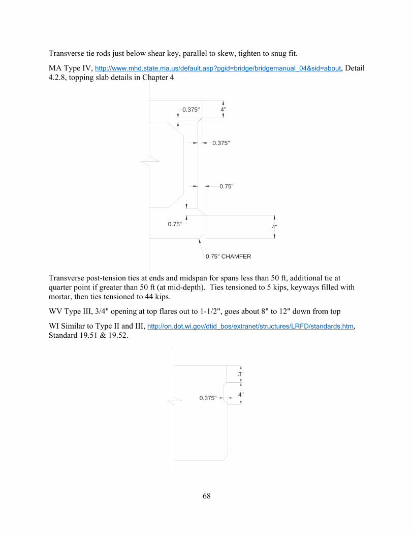
Response: 3/4" opening at top flares out to 1-1/2" similar to Type III. The keyway goes about 8" to 12" down from top of beam depending on the depth of beam.
Q3. Based upon your agency’s experience, please rate the above geometries in terms of performance related to cracking and leakage at the longitudinal joints, where “1” represents no cracking and leakage and “5” represents major cracking and excessive leakage.
Response:
Type I Type II Type III Type IV Type V
3 3 3 3 3
Q4. What is your greatest performance problem related to cracking and seepage at these joints? What documentation do you have with regard to this problem (data, specifications, construction practices, etc.)? In addition, do you believe that cracking is related to environmental conditions and/or policy (such as road salt and/or restriction on use)?
Response: truck loads and salt exposure.
Q5. Based upon your experiences, which are the best practices for keyway construction as related to the box beam performance?
Response: No preparation; Non-shrink grout; Single-stage post-tensioning
13
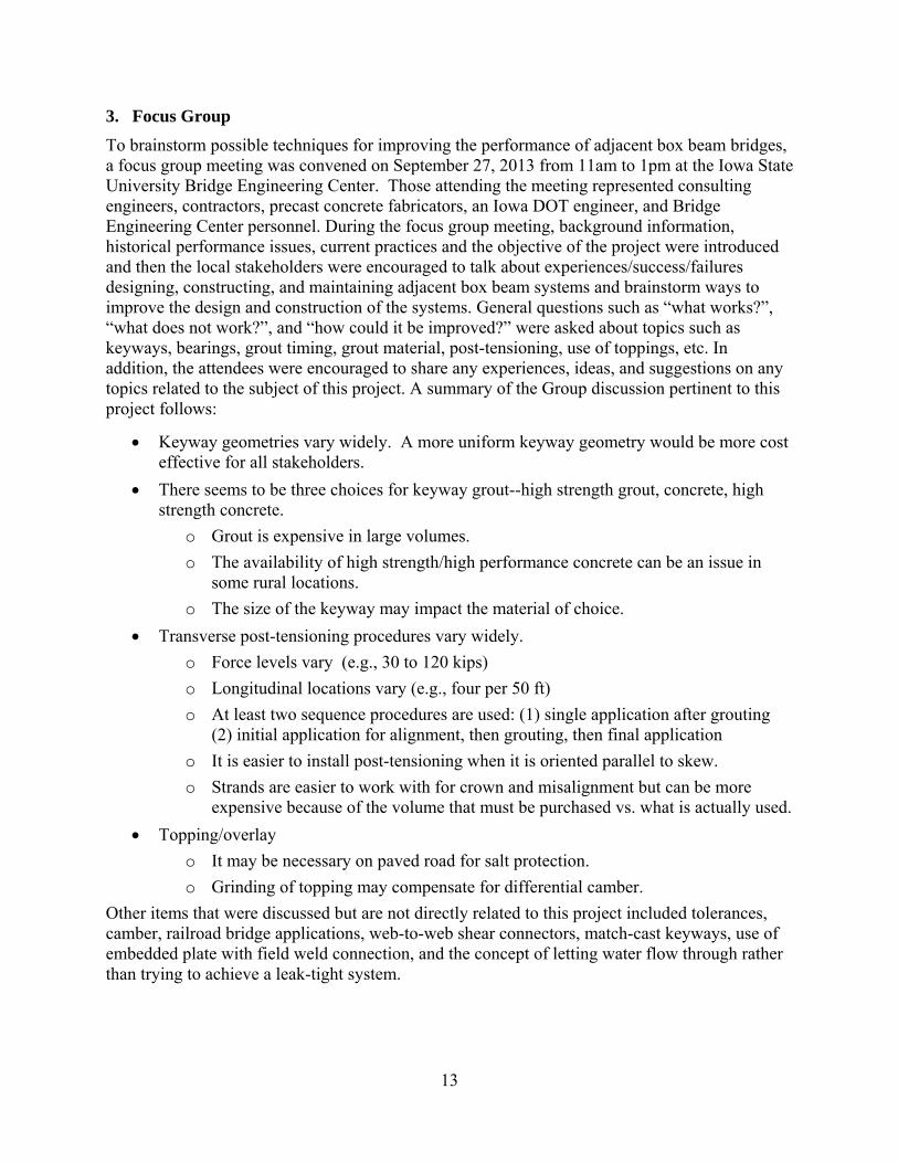
3. Focus Group
To brainstorm possible techniques for improving the performance of adjacent box beam bridges, a focus group meeting was convened on September 27, 2013 from 11am to 1pm at the Iowa State University Bridge Engineering Center. Those attending the meeting represented consulting engineers, contractors, precast concrete fabricators, an Iowa DOT engineer, and Bridge Engineering Center personnel. During the focus group meeting, background information, historical performance issues, current practices and the objective of the project were introduced and then the local stakeholders were encouraged to talk about experiences/success/failures designing, constructing, and maintaining adjacent box beam systems and brainstorm ways to improve the design and construction of the systems. General questions such as “what works?”, “what does not work?”, and “how could it be improved?” were asked about topics such as keyways, bearings, grout timing, grout material, post-tensioning, use of toppings, etc. In addition, the attendees were encouraged to share any experiences, ideas, and suggestions on any topics related to the subject of this project. A summary of the Group discussion pertinent to this project follows:
Keyway geometries vary widely. A more uniform keyway geometry would be more cost effective for all stakeholders.
There seems to be three choices for keyway grout--high strength grout, concrete, high strength concrete.
o Grout is expensive in large volumes.
o The availability of high strength/high performance concrete can be an issue in some rural locations.
o The size of the keyway may impact the material of choice.
o Longitudinal locations vary (e.g., four per 50 ft)
o At least two sequence procedures are used: (1) single application after grouting (2) initial application for alignment, then grouting, then final application
o It is easier to install post-tensioning when it is oriented parallel to skew.
o Strands are easier to work with for crown and misalignment but can be more expensive because of the volume that must be purchased vs. what is actually used.
Topping/overlay
o It may be necessary on paved road for salt protection.
o Grinding of topping may compensate for differential camber.
Other items that were discussed but are not directly related to this project included tolerances, camber, railroad bridge applications, web-to-web shear connectors, match-cast keyways, use of embedded plate with field weld connection, and the concept of letting water flow through rather than trying to achieve a leak-tight system.
14
4. Literature Search
A comprehensive literature search was conducted to collect information relevant to the project. These data were gathered, categorized, and summarized so as to guide subsequent tasks. It is worth noting that a complete understanding of the current state-of-art and the state-of-practice is extremely important and invaluable at finalizing the plans for the analytical and experimental investigations of this project and ensuring that the work completed in this project does not duplicate work already completed. It should be noted that NCHRP Synthesis 393 by Russell [2009] described current concrete box beam practices from multiple Departments of Transportation (DOT) at multiple levels and also provides extensive literature search results from before 2008.
The literature search for this project will be summarized as follows. First, NCHRP Synthesis 393 will be summarized including the conclusions and recommendations. Second, literature published before 2008 will be reviewed to take note of the important information beneficial to this project. Finally, literature published after 2008 will be reviewed especially those with a connection to the results of NCHRP Synthesis 393. Finally, literature will be summarized, synthesized, and then categorized as they relate to laboratory testing, field testing, and Finite Element (FE) analysis. Note that to provide a brief summary of each piece of literature, “Take Away” points for each are provided after each general summary (with the exception of NCHRP Synthesis 393).
4.1 NCHRP Synthesis 393
The NCHRP Synthesis report by Russell [2009] summarized the observed types of distress associated with the joints used in adjacent box girder bridge systems including longitudinal cracking along the joint material and box beam interface, water and salt leakage through the joint, cracking within the grout, spalling of the grout, spalling of the girder corners, differential vertical movement, corrosion of transverse ties and longitudinal prestressing strands, freeze-thaw damage to the grout and concrete near the joint. Note that the most common types of distress are longitudinal cracking along the grout and box beam interface, water and salt leakage through the joint, and reflective cracks that are commonly observed in the road surface.
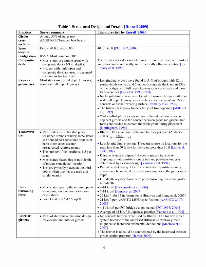
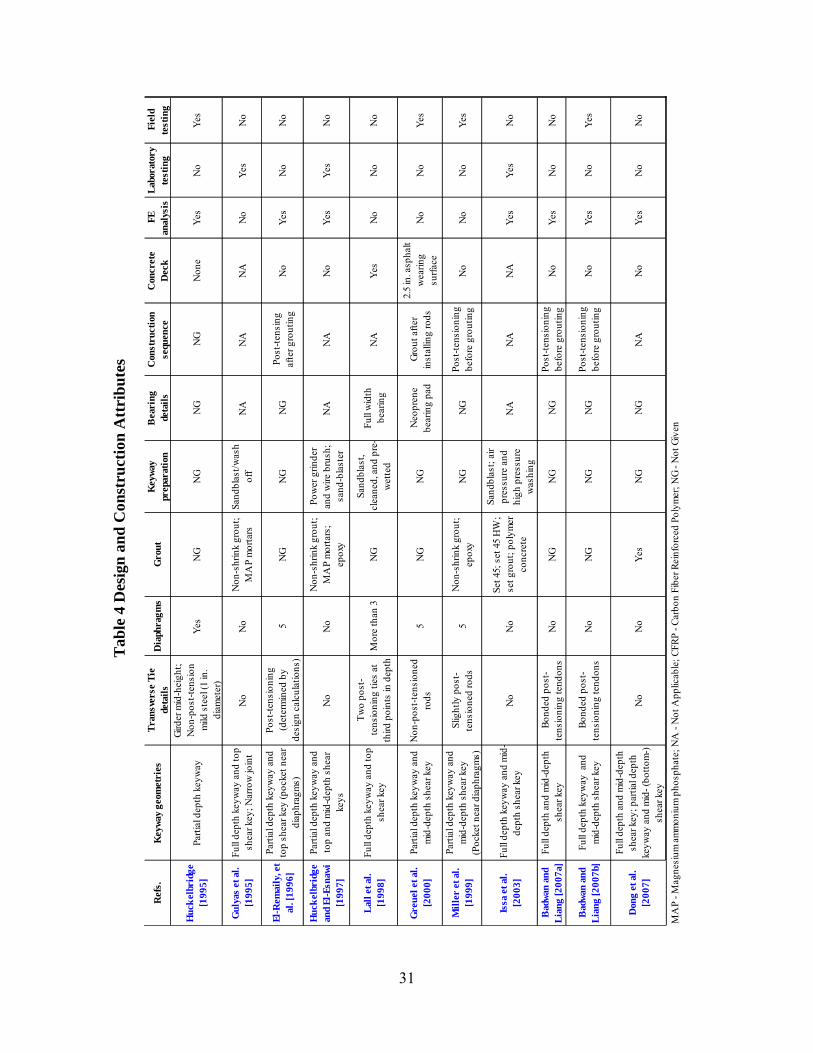
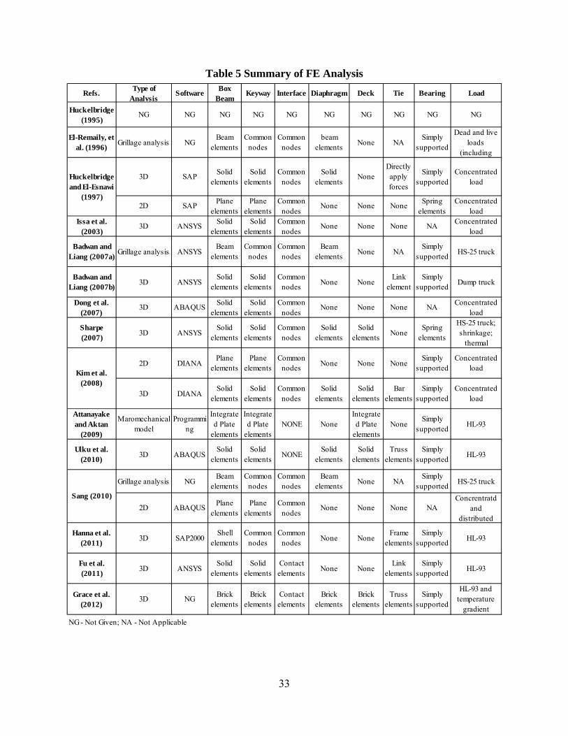
Based on the survey of state DOTs and the literature search, Russell [2009] also began the process of identifying factors impacting the long-term performance of adjacent box beam bridge systems. In the synthesis, practices for structural design and detailing for adjacent box girder bridges from state DOTs and the literature were summarized as shown in Table 1. Specifications and construction practices for adjacent box girder bridges from state DOTs and the literature were also summarized as tabulated in Table 2. Finally, the recommended and not-recommended design and construction practices were summarized as tabulated in Table 3.
Russell [2009] indicates that keyway configurations consist of partial depth and full depth keyways. In the United States, three typically used generic partial depth keyway geometries are the Types I, II and III keyways and one generic full depth keyway geometry is the Type IV keyway as shown in Figure 1 (note that in Figure 1 the box beams have been shown to be in direct contact – this may or may not always be the case; however, sweep is typically removed with the application of post-tensioning). Conversely, the typically used Japanese keyway is the full depth keyway Type V shown in Figure 1. El-Remaily et al. [1996] reported that longitudinal cracking was seldom found in the adjacent box beam bridges with the Type V full-depth keyway.
15
Table 1 Structural Design and Details [Russell 2009] Practices Survey summary Literature cited by Russell [2009] Girder cross sections
Around 50% of states use AASHTO/PCI-shaped box beams
Span lengths
Below 20 ft to above 80 ft 40 to 140 ft [PCI 1997; 2004]
Bridge skew 0º-60º; Most common: 30º Composite deck
Most states use simple spans with composite deck (3-9 in. depth);
Bridges with multi-span and composite deck are usually designed continuous for live load.
The use of a deck does not eliminate differential rotation of girders and is not an economically and structurally efficient solution [El-Rmaily et al. 1996]
Keyway geometries
Most states use partial depth keyways; some use full depth keyways
Longitudinal cracks were found in 54% of bridges with 12 in. partial depth keyway and 6 in. depth concrete deck and in 23% of the bridges with full depth keyways, concrete deck and more transverse ties [Lall et al. 1997; 1998].
No longitudinal cracks were found in Japanese bridges with 6 in. wide full depth keyway, cast-in-place concrete grout and 2-3 in. concrete or asphalt wearing surface [Remaily et al. 1996]
The full depth keyway hinders the joint from opening [Miller et al., 1999]
Wider full-depth keyways improves the interaction between adjacent girders and the contact between grout and girders, but forms are needed to contain the fresh grout during placement [Nottingham, 1995]
Transverse ties
Most states use unbonded post-tensioned strands or bars; some states use bonded post-tensioned strands or bars; other states use non-presteressed reinforcements
The number of tie locations: 1-5 per span
Most states placed ties at mid-depth of girders (one tie per location)
Ties are typically placed at the third points when two ties are used at a single location
Illinois DOT equation for the number ties per span (Anderson 2007): span
1 125
N
Less longitudinal cracking: Three transverse tie locations for the span less than 50 ft five for the span more than 50 ft [Lall et al. 1997; 1998]
Durable system in Japan: 4-7 evenly spaced transverse diaphragms with post-tensioning ties and post-tensioning is determined by flexural design [Yamane et al. 1994]
Partial depth keyway: Due to eccentricity of post-tensioning, cracks may be induced by post-tensioning ties at the girder mid-depth
Full depth keyway: Good with post-tensioning ties at the girder mid-depth
Post-tensioning force
Most states specify the required post-tensioning force without extensive calculations
For 11 states: 0.5-12.5 kip/ft
4-14 kip/ft [El-Remaily et al. 1996] 7-14 kip/ft [Hanna et al. 2007] 27 kip/ft for 15 in. beam depth [Badwan and Liang et al. 2007] 21 kip/ft per AASHTO LRFD specification [AASHTO 2007;
2008] 4-11 kip/ft per PCI bridge design manual [PCI 1997; 2004] Average of 11 kip/ft is Japanese practice [Yamane et al. 1994]
Exterior girders
Most of states have the same design for exterior and interior girders
No concrete barriers were used by Illinois DOT for box girder system because of the increased stiffness of exterior girders might cause increased differential deflections [Macioce et al. 2007]
The barrier load could be counteracted by the increased exterior girder section property [Harries 2006].
16
Table 2 Specifications and Construction Practices [Russell 2009] Practices Survey summary Literature cited by Russell [2009] Standard specifications (AASHTO 2002)
No guidelines are provided for the design and construction of the connection details of adjacent box girders
LRFD specifications (AASHTO 2007; 2008)
A compression depth (≥7 in.) should be provided with a transverse post-tensioning ≥ 0.25 ksi
Post-tensioning ties are required to be placed at the centerline of the keyway
Bearing types Plain elastometic bearing: ¾ of respondents Laminated elastomeric bearing: ¼ of respondents Full-width support or full-point support on ends: 42% of
states for each; Two-point support and one-point support: the other states
Uneven seating: half the respondents (especially for a full-width support)
Construction sequence
One stage construction: Erect all beams and connect them at one time
Two stage construction: a variety of sequences Grout before or after post-tensioning: 50% of states for
each Grout after post-tensioning shows higher cracking
resistance Construction sequence is affected by the skew of the
bridge and intermediate diaphragm locations
Greuel et al. [2000] reported that spalling of beam bottom flanges occurred near the shear key for the two half bridges when the shear key was not grouted prior to post-tensioning
Differential camber
Restrictions for differential camber: 1/3 of respondents Maximum differential camber: 0.5 in. (½ of
respondents) Others: 0.25 in. in 10 ft; 0.75 in. maximum; 1 in.
relative deflection for high and low beams in one span Improving methods: load high beam before grouting
and post-tensioning; adjust bearing seat elevations; concrete or asphalt topping; preassemble girders before shipment
Keyway preparation
Sandblast keyway: 45% of states Sandblast and powerwash keyway:1/3 of respondents
Poor adherence of keyway mortar [Attanayake and Aktan 2008]
Grout materials and practices
Nonshrink grout: 40% of respondents; mortar: 25% of respondents; epoxy grout, epoxy resin, or concrete topping: other respondents
No curing: 40% of respondents; curing compounds: 5%; wet curing: around 45% of states
Most of states manually place the grout
High-quality joint: prepackage mix with predetermined amount of water (e.g., prepackaged magnesium-ammonium-phosphate grout with pea gravel) [Nottingham 1995]
Improvements by West Virginia DOT [El-Remaily et al 1996]: a pourable epoxy replacing a nonshrink grout; sandblasting surfaces; post-tensioning ties.
Andover Dam Bridge in Maine: wider shear key rapidly grouted with shrinkage-restrained self-consolidating concrete [Russell 2009]
Illinois DOT [2008]: use a mechanical mixer for mixing nonshrink grout; place with a pencil vibrator; smooth surface; cover with the cotton mats for more than 7 days
17
Table 3 Recommended Practices [Russell 2009] Practices Recommended Not recommended Design practices Full depth keyway: grouted easily
Post-tensioning transverse ties: eliminating tensile stresses in the shear key
Cast-in-place reinforced concrete deck (compressive strength of more than 4 ksi and thickness of more than 5 in.): restrains longitudinal deck cracking
Non-tensioned transverse ties: no crack resistant ability
Construction practices
Form the void using stay-in-place expanded polystyrene
Sandblast the keyway surface before shipment: ensuring a better bonding surface for the grout
Powerwash the keyway surfaces (compressed air or water) before erection of girders: ensuring a better surface for the grout
Grout keyways before post-tensioning: the grout under compression
Grout with high bond strength: limit cracking Provide suitable curing for the grout: developing
desired strength and minimize shrinkage effects Provide suitable wet curing for the concrete deck
(more than 7 days): ensuring durable surface and minimize shrinkage cracks
Use asphalt wearing surface with non-water proofing membrane: water gathers under the asphalt
Use non-prepackaged products for the keyway grout
4.2 Publications Before 2008
Huckelbridge et al. [1995] revealed that precast prestressed adjacent box beams have been mostly used for the construction of bridges with short and medium spans ranging from 30 ft to 100 ft. The authors conducted field testing of several adjacent box girder bridges and the test results from two of these bridges were summarized in the 1995 report; one for a simply supported bridge and one for a four-span continuous bridge. A dump truck with a front axle weight of 12 kips and tandem axles weighing 38 kips was used to conduct on-site, controlled tests. During those tests, deflection transducers were installed on the bottom of adjacent beams near the keyway so as to record the relative deflections between those box beams; flexural strains were also measured on the girder bottom. The maximum relative deflection was found to be 0.2 and 0.15 in. for the two bridges, respectively. According to results from FE analysis (details of FE analysis were not given) and field tests, the authors pointed out that intact shear keys, should not permit relative deflection of more than 0.001 in. between adjacent girders. As they expected, reflective cracks were found around the shear keys on both bridges. Partially fractured shear keys were generally found close to the daily wheel positions and driving lanes with heavy truck traffic. However, they did note that the partially fractured shear keys still displayed adequate lateral live load distribution characteristics. The addition of lateral tie bars was found to have insignificant influence on shear key performance. Note that the transverse tie bars used in the tested bridges wer made of 1 in. diameter mild steel and spaced at no more than 25 ft and were not post-tensioned.
Take Away Points:
Intact shear keys (i.e., crack free) should not permit relative deflection between adjacent box beams.
18
Partially fractured shear keys still have adequate strength to distribute live loads laterally.
Mild steel lateral tie-bars have insignificant influence on shear key performance.
In the experimental work by Gulyas et al. [1995], the performance of grouted keyways using non-shrink grouts and magnesium ammonium phosphate mortars were studied and compared. Three types of tests were conducted including a direct vertical shear test considering truck loads on the bridge, a direct transverse tension test considering transverse creep and shrinkage effects, and a direct longitudinal shear test considering longitudinal creep and shrinkage effects. All the 16 tested specimens had small dimensions and grout strengths ranging from 5.9 to 7.3 ksi. They found that the composite keyway specimens using magnesium ammonium phosphate mortars showed higher direct tensile bond strengths, vertical shear, and longitudinal shear than those of the non-shrink grout keyway specimens. They also found that magnesium ammonium phosphate mortars showed significantly lower chloride absorption ability, which is of benefit for roadways exposed to salts or sea sprays. Finally, the authors recommended not using non-shrink grouts for the keyway unless the tensile and shear strengths satisfy the requirements in their study.
Take Away Points:
Mortars used in shearkeys consisting of ammonium phosphate displayed high bond and shear strengths and also had low chloride absorption.
El-Remaily, et al. [1996] compared the American and Japanese approaches to designing adjacent concrete box beam bridges primarily because longitudinal cracking was very rarely associated with Japanese box beam bridges. It was found that the primary differences between American and Japanese designs were: (1) the size and shape of longitudinal joints and (2) the amount of transverse post-tensioning. After further review, the authors proposed a new precast prestressed box girder bridge design along with a design methodology suitable for U.S. practice. The proposed design methodology takes the transverse diaphragms as the only components which sustain the post-tensioning forces from the post-tensioning ties. The transverse diaphragms are connected at the joints and laterally distribute live loads among those box girders. A grillage analysis was performed using beam elements with common nodes for the diaphragms and beams and considering dead and live loads (including barriers). Working stress methodologies are used to compute the transverse stresses in the top and bottom of the diaphragms after the bending moments in the diaphragms are derived from the grillage model. The post-tensioning is determined to counteract the calculated stresses in the diaphragms such that no lateral tensile stress is induced in the diaphragms. The author’s parametric studies indicated that the needed transverse post-tensioning remains constant per unit span length and varies significantly with the bridge width. This method was adopted by the Precast/Prestressed Concrete Institute (PCI) Bridge Design Manual [PCI 2003]. The authors described a design example but provided no information on neither experimental validation nor analytical evaluations using a rigorous finite element approach.
Take Away Points:
The primary differences between American and Japanese designs are: (1) the size and shape of longitudinal joints and (2) the amount of transverse post-tensioning.
19
The amount of post-tensioning remains constant on a per foot basis (for constant width of bridge); the amount of post-tensioning needed varies with bridge width.
A study conducted in the State of Ohio examined the performance of the State’s standard box beam shear key design, investigated the problem causing shear key failure and developed new types of keyway connection details [Huckelbridge and El-Esnawi, 1997]. Initially, a 3D FE model of a three-box beam bridge with a length of 40 ft and a width of 12 ft was established. A concentrated load simulating a truck wheel load was applied on the center of the interior beam. The analytical results indicated that transverse tensile stresses in the bridge top flange are the main factor causing many shear key failures. To deal with the issue, a new type of shear key was proposed by placing the shear key at the neutral axis of the beam cross section. FE results showed that the proposed shear key sustained much smaller tensile stresses which would not cause shear key cracking nor failure. To complete the examination, small scale testing of a multi-beam bridge cross section was conducted. The small scale specimens are slices of the three-beam assembly with a length of 12 in., a width of 144 in., and a depth of 33 in. Static and cyclic loads were applied at the center of these specimens. The experimental results showed that the mid-depth shear key design (only the shear key was grouted instead of the whole keyway) had significantly improved the static load carrying capacity and provided a longer fatigue life than the previous shear key design. In the end, the authors also proposed a water-proofing shear key design with a mid-depth shear key, which uses water-proofing membrane, asphalt topping and foam filler above the shear key. The test results indicated that this shear key design maintained watertightness after fatigue testing in the laboratory environment. However, further evaluations at real bridge sites were noted to be needed.
Take Away Points:
A shear key placed at mid-depth of the beam must resist much smaller tensile stresses than that which would cause cracking.
Research conducted by Lall et al. [1998] compared the long-term performance of a partial depth shear key system and a modified, full-depth shear key/transverse tie system based on a survey of bridges in New York State. The modified full-depth shear key/transverse tie system was developed based on the results of bridge inspections in the State of New York and information from other states - in particular the State of Michigan. Note that the new system possesses two post-tensioning ties located at the third points of the girder depth instead of one tie at the girder mid-depth. Survey results indicated that the new full-depth shear key/transverse tendon system showed superior cracking prevention ability and reduced the frequency of reflective cracking in the deck. As a result of the work, the authors recommended using the new full-depth shear key for future adjacent box beam bridges. Additionally, the authors recommended the use of full-width bearing pads, more reinforcement in the concrete topping, higher transverse post-tensioning forces and two ties at each post-tensioning location.
Take Away Points:
Two ties at each post-tensioning location are preferred to single ties. Full-depth shear keys show improved performance.
20
Additional reinforcement in a cast-in-place topping also resulted in improved performance.
Higher transverse post-tensioning also led to improved performance.
Miller et al. [1999] evaluated the performance of box girder shear keys with different shear key locations and different grouting materials. Three types of specimens, made of four box beams, were fabricated with a top shear key plus non-shrink grout, a mid-depth shear key plus non-shrink grout, and a top shear key plus epoxy grout. The specimens were fabricated and tested outside under real environmental conditions and thus experienced continuous temperature gradients. For each specimen a total of 1,000,000 cycles of load (20 kips) were applied on one interior beam and then moved to the other interior beam. The cracks that developed in the shear keys were inspected using ultrasonic pulse velocity. A static load (20 kips) was also applied on the interior beams separately or simultaneously to check the live load distribution characteristics before and after the development of cracks caused by cyclic loads. The test results indicated that temperature induced stresses – when a shear key was located near the top of the beam – were consistently high enough to cause significant cracking of the shear key material. These cracks significantly propagated from the two ends near the supports to the bridge mid-span after cyclic loads. Conversely, when the shear key was placed at member mid-depth, the shear key did not experience significant cracking under neither thermal nor live loads. They also found that live loads would not cause new cracking but appeared to propagate existing thermal cracks. In addition, static load test results showed that the cracking in the shear key had no remarkable effect on the live load distributions among box beams, but did cause leakage in the joints. In the end, Miller et al. [1999] recommended the use of a grout material with high bond strength for the joints of the adjacent box girders even though this results in some concerns such as thermal compatibility due to the high thermal expansion coefficient of the epoxy, undesired failure in the concrete rather than the epoxy, inconvenience, and the use of poisonous methylethyketone (MEK) for the epoxy.
Take Away Points:
Shear keys located near the top of the beam can experience stresses high enough to induced cracking from temperature changes.
Cracking tends to start near the ends of the beams. Shear keys located near the beam mid-depth did not experience cracking of
the joint material.
Follow-up work by Greuel et al. [2000] studied the field performance of a bridge constructed with a mid-depth shear key. Only the shear key was grouted and the gap above the shear key was filled with compacted sand with a sealant encapsulating the exposed longitudinal joint. Non-prestressed tie rods were used to connect the box beam together before grouting. Field testing was conducted using four Ohio DOT dump trucks - with a total weight ranging from 27 to 32 kips - at various transverse positions. In addition to the static load test, the bridge responses were continuously collected when trucks travels cross the bridge at a speed of around 50 miles per hour. The results indicated that there was no appreciable differential displacement between girders. The authors further concluded that the shear key and transverse rod system adequately resisted the applied live loads.
21
Take Away Points:
A bridge with only the shear key grouted and non-tensioned transverse rods can result in a bridge that shows no differential displacement under live loads.
Issa et al. [2003] conducted small scale tests of keyway specimens to investigate the performance of four grout materials using direct shear, direct tension, and flexural tests. The chloride permeability and shrinkage of the four grouts were also measured. The test results indicated that the polymer concrete showed the highest shear, tensile and flexural strengths. The polymer concrete also had superior chloride resistance and less shrinkage compared to the other grouts while set grout had significant shrinkage due to its high water content. In addition, FE analysis of tension test specimens showed that the polymer concrete specimens sustained the highest load with a minimum of cracking and crushing compared to others.
Take Away Points:
Polymer concrete has good strength and chloride resistance characteristics.
Badwan and Liang [2007a] performed a grillage analysis to determine the needed transverse post-tensioning for a precast adjacent, solid, multi-beam deck. The grillage model was established using beam elements for the beams while also considering the stiffness at the keyway locations. Parametric studies were performed to investigate the importance of factors such as skew, deck width, thickness, and span length on the design of such a system. The results indicate that the required post-tensioning stress decreases with an increase in the deck width, deck thickness, and skew angles (especially for skew angles greater than 30 degrees). The authors note that the influence of skew is due to the fact that transverse bending in the skew direction decreases with skew angle. The span length affects the needed post-tensioning stress when the bridge skew is very large. In the end, they concluded that it is adequate to design the needed post-tensioning for such a system (especially with high skew) based on current AASHTO specifications.
Take Away Points:
The amount of post-tensioning decreases with an increased deck width, thickness, and skew.
Span length affects the needed post-tensioning when the skew is very large.
A literature search conducted by Badwan and Liang [2007b] revealed that little research has been conducted to study the performance of full depth keyways even though testing has been conducted to investigate the behavior of partial depth keyways. Thus, the authors implemented field testing and associated FE analysis of a post-tensioned adjacent solid box girder bridge with full depth keyways, mid-depth shear keys, and transverse post-tensioning. The 3D FE model was established using solid elements for the concrete and grout and link elements were used for the post-tensioning tendons. During testing, longitudinal strains in the girders were recorded. The adequacy of the FE model was validated using the strain data. Based upon the testing and analytical results, the authors concluded that the lateral load distribution was not affected as long as no cracks were induced in the shear keys. It should be noted that serviceability issues caused by shear key cracking were not addressed by the authors.
22
Take Away Points:
Lateral load distribution is not impacted by keyway geometry as long as no cracks are induced in the shear keys.
Dong et al. [2007] established 3D finite element models to investigate and compare the behavior of the three types of joints shown in Figure 3. Finite element models were established using solid elements for both the concrete and grout. Parametric studies were then conducted considering the three types of joints and three strengths of grouts. The results showed that no cracking was found in the FE model of Joint A but significant stress concentrations and cracking occurred in Joints B and C. They concluded that cracks developed in Joints B and C were due to the significant change of the keyway shape. In addition, they also found that higher strength grout material does not reduce the cracks.
Take Away Points:
Radical changes in shearkey geometry (i.e., very sharp corners) may result in higher stress levels.
(a) Joint A (b) Joint B (c) Joint C
Figure 3 Basic Shearkey Shapes
Sharpe [2007] conducted extensive FE element analysis of Precast/Prestressed Concrete Institute (PCI) style and Texas Department of Transportation (TxDOT) style box girder bridges to investigate the performances of the shear keys. FE models were established using solid elements for the beams, diaphragms, and keyways and elastomeric bearing pads were modeled using spring elements whose vertical and lateral stiffnesses were determined based on the material properties of the bearing pad and basic mechanics of materials. The AASHTO HS-25 truck load, strains due to shrinkage, and a temperature gradient were applied to those bridge models. Sharpe considered two types of failure in the shear keys: debonding and cracking (with different failure stresses). The FE analysis results indicated that reflective cracking was due to high tensile stresses in the shear keys caused by temperature gradients and shrinkage strains instead of live loads. It was further found that these cracks usually developed near the supports instead of at the bridge mid-span. Analytical results showed that composite slabs are most effective at alleviating high tensile stresses in the shear keys although post-tensioning and full-depth keyways also
23
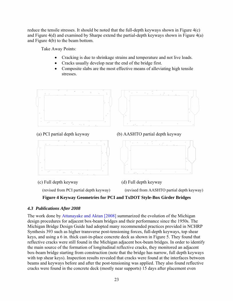
reduce the tensile stresses. It should be noted that the full-depth keyways shown in Figure 4(c) and Figure 4(d) and examined by Sharpe extend the partial-depth keyways shown in Figure 4(a) and Figure 4(b) to the beam bottom.
Take Away Points:
Cracking is due to shrinkage strains and temperature and not live loads. Cracks usually develop near the end of the bridge first. Composite slabs are the most effective means of alleviating high tensile
(revised from PCI partial depth keyway) (revised from AASHTO partial depth keyway)
Figure 4 Keyway Geometries for PCI and TxDOT Style-Box Girder Bridges
4.3 Publications After 2008
The work done by Attanayake and Aktan [2008] summarized the evolution of the Michigan design procedures for adjacent box-beam bridges and their performance since the 1950s. The Michigan Bridge Design Guide had adopted many recommended practices provided in NCHRP Synthesis 393 such as higher transverse post-tensioning forces, full-depth keyways, top shear keys, and using a 6 in. thick cast-in-place concrete deck as shown in Figure 5. They found that reflective cracks were still found in the Michigan adjacent box-beam bridges. In order to identify the main source of the formation of longitudinal reflective cracks, they monitored an adjacent box-beam bridge starting from construction (note that the bridge has narrow, full depth keyways with top shear keys). Inspection results revealed that cracks were found at the interfaces between beams and keyways before and after the post-tensioning was applied. They also found reflective cracks were found in the concrete deck (mostly near supports) 15 days after placement even
24
before construction the barrier or applying live loads. They concluded that reflective cracks are due to effects such as hydration heat and drying shrinkage. Take Away Points:
Cracking forms at the interface between the joint material and the box beam concrete.
Reflective cracks are principally due to shrinkage.
Figure 5 Typical Michigan Keyway Geometry and Post-tensioning
Kim et al. [2008] presented recent applications of precast adjacent box-beam bridges with full-depth keyways with mid-depth shear keys grouted with cast-in-place concrete and transverse post-tensioning in South Korea. The authors performed 2D FE analysis of three box beam sections without transverse post-tensioning to investigate the performance of four placement conditions for the shear key (i.e., no shear key, top shear key, mid-depth shear key, and bottom shear key) as shown in Figure 6(a), Figure 6(b), Figure 6(c), and Figure 6(d). Various loading and boundary conditions were applied. Based on the beam differential deflections results, it was indicated that the top shear key, the mid-depth shear key, and the bottom shear keys all show superior performance than that of no shear key and the mid-depth shear key was the best of the four configurations. Sang [2010] confirmed their results and concluded that the location of the shear key does not significantly affect the performance of full-depth keyways. To verify the feasibility of the proposed full depth keyway (with the mid-depth shear key grouted with cast-in-place concrete and high transverse post-tensioning), Kim et al. [2008] conducted flexural testing and 3D FE modeling of a three box beam specimen. The failure and cracking loads both exceeded the ultimate load and service load based on the Korea design code which is similar to the AASHTO bridge design specifications. No longitudinal cracks were found in the joints when the specimen sustained service and ultimate loads. The measured relative displacements indicated that effective load transfer by the shear key connections was occurring. Kim et al. [2008] conducted fatigue testing (2 million cycles) of the three-box beam specimen. The test results indicated that no cracks were found in the longitudinal joints and the specimen exhibited excellent fatigue resistance with the residual deflection being recovered 24 hours after fatigue testing. Finally, Kim et al. [2008] applied the proposed full depth keyway to a real bridge. Field tests were conducted using static and moving dump trucks on the bridge. They concluded that the box-beam bridge performed well structurally under static and moving dump truck loads. Further, no longitudinal cracking in the keyway joints was reported by the authors. It should be pointed
25
out that long term behavior of the three box beam specimens and the constructed bridge were not evaluated.
Take Away Points:
Mid-depth shearkey placement results in the best performing joint – especially when used with high post-tensioning and cast-in-place concrete.
(a) No shear key (b) Top shear key
(c) Mid-depth shear key (d) Bottom shear key
Figure 6 Common shearkey locations
Attanayake and Aktan [2009] developed a simple analytical model consisting of plate elements based on the macromechanics concept. In this model, the plate element represents a combination of two half box-beam sections, one shear key and concrete deck. Namely, the cross-section of the plate element has the identical section properties as those of the combination cross-section. The stiffnesses of the box-beam sections, shear keys and concrete deck are calculated and then incorporated into the plate elements. The transverse moments along the longitudinal joints between the adjacent beams were determined from the macromechanical model based on the AASHTO LRFD bridge design specifications. These calculated moments were then used to determine the needed transverse post-tensioning. Further, the authors demonstrated a design example in their paper. However, the macromechanical model fails to simulate the interaction between the keyways and beams due to different material properties (i.e., grout and concrete) and bond at the interfaces.
Take Away Points:
Machromechanical modelling fails to simulate the interaction between the keyway and the beam.
Follow-up work by Ulku et al. [2010] proposed a rational design procedure utilizing the macromechanical model developed by Attanayake and Aktan [2009] to calculate the transverse moments along the transverse joints and thus determine the required transverse post-tensioning. The concept is to use multi-stage post-tensioning to minimize the longitudinal cracking in the keyway and reflective cracking in the concrete deck. A 3D FE model was established using solid elements for the beams, keyways, diaphragms and deck. Multi-stage post-tensioning after grouting the keyway and after the deck placement was simulated. They concluded that the two stage post-tensioning process is effective at reducing cracking issues for the bridge subjected to
26
dead and live loads and temperature effects. However, in their designs, the tensile stresses in the deck near the fascia beams due to live loads are significant and may not be easily offset by two-stage post-tensioning. They also found that the temperature gradient is the main factor causing the cracks which developed at the interface of the top shear keys. Another cause of cracks is that the post-tensioning is not uniformly distributed at the keyway because of shear lag.
Take Away Points:
Two stage post-tensioning may minimize longitudinal cracking. Temperature gradient is the main factor causing cracks to develop at the joint
interface.
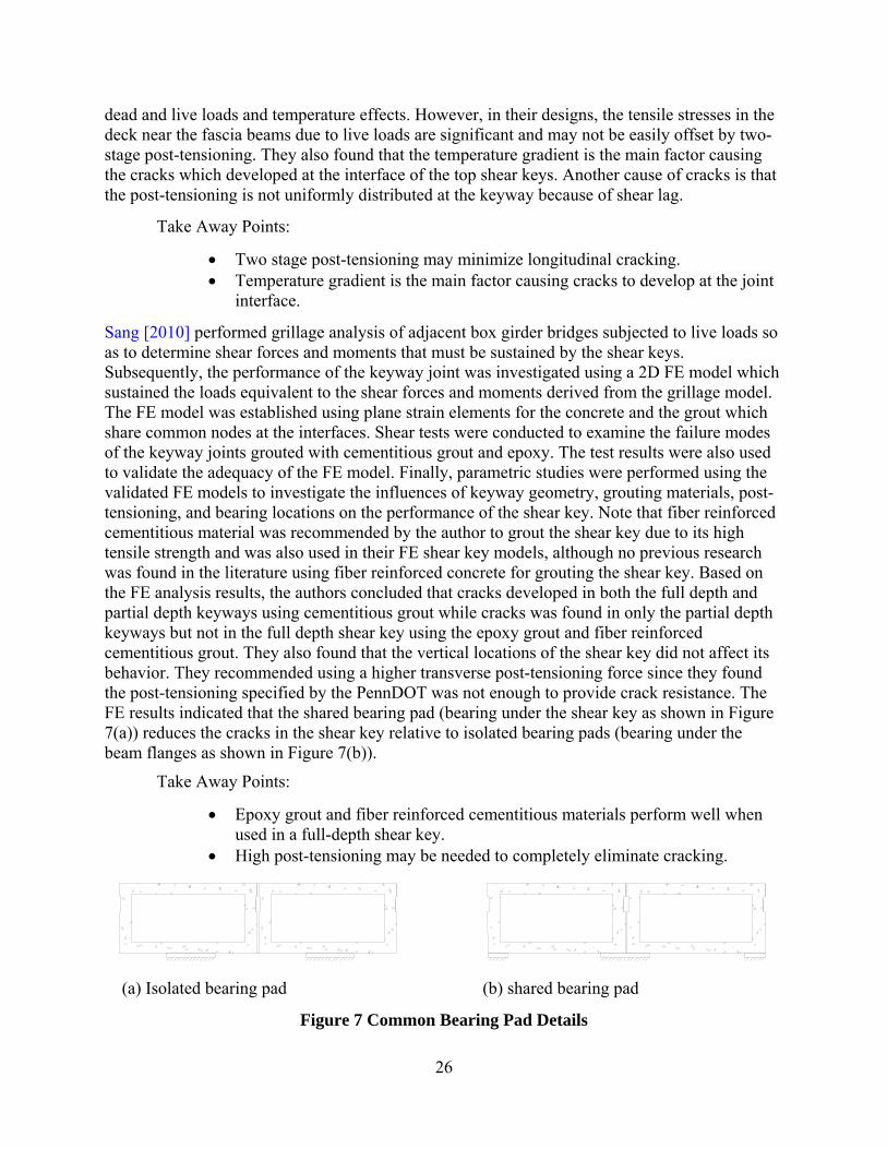
Sang [2010] performed grillage analysis of adjacent box girder bridges subjected to live loads so as to determine shear forces and moments that must be sustained by the shear keys. Subsequently, the performance of the keyway joint was investigated using a 2D FE model which sustained the loads equivalent to the shear forces and moments derived from the grillage model. The FE model was established using plane strain elements for the concrete and the grout which share common nodes at the interfaces. Shear tests were conducted to examine the failure modes of the keyway joints grouted with cementitious grout and epoxy. The test results were also used to validate the adequacy of the FE model. Finally, parametric studies were performed using the validated FE models to investigate the influences of keyway geometry, grouting materials, post-tensioning, and bearing locations on the performance of the shear key. Note that fiber reinforced cementitious material was recommended by the author to grout the shear key due to its high tensile strength and was also used in their FE shear key models, although no previous research was found in the literature using fiber reinforced concrete for grouting the shear key. Based on the FE analysis results, the authors concluded that cracks developed in both the full depth and partial depth keyways using cementitious grout while cracks was found in only the partial depth keyways but not in the full depth shear key using the epoxy grout and fiber reinforced cementitious grout. They also found that the vertical locations of the shear key did not affect its behavior. They recommended using a higher transverse post-tensioning force since they found the post-tensioning specified by the PennDOT was not enough to provide crack resistance. The FE results indicated that the shared bearing pad (bearing under the shear key as shown in Figure 7(a)) reduces the cracks in the shear key relative to isolated bearing pads (bearing under the beam flanges as shown in Figure 7(b)).
Take Away Points:
Epoxy grout and fiber reinforced cementitious materials perform well when used in a full-depth shear key.
High post-tensioning may be needed to completely eliminate cracking.
(a) Isolated bearing pad (b) shared bearing pad
Figure 7 Common Bearing Pad Details
27
Fu et al. [2011] proposed an approach to designing the required post-tensioning for solid, multi-beam bridge system based on the shear friction concept and FE modeling techniques. The FE models were established using solid elements, link elements, and contact elements for the beams, post-tensioning ties and interfaces between the shear key and the beam, respectively. The adequacy of the FE models were validated against the strain data measured during field tests using an onsite controlled dump truck. Based on the FE results, the author recommended different levels of post-tensioning for bridges with different span lengths. The authors found that the boundary conditions had great influence on the predicted bridge response. They found that the post-tensioning does not affect the live load distribution until cracks develop in the keyway and/or concrete topping. Finally, the authors gave some recommendations for improving the use of shear keys in Maryland (e.g., using a two-staged construction sequence {e.g., 16.7% and 100% of the designed post-tensioning of design level before and after grouting the keyways} and using full-depth shear keys).
Take Away Points:
Bridges of different span lengths may require different amounts of post-tensioning.
Two-stage post-tensioning may help reduce the development of cracks.
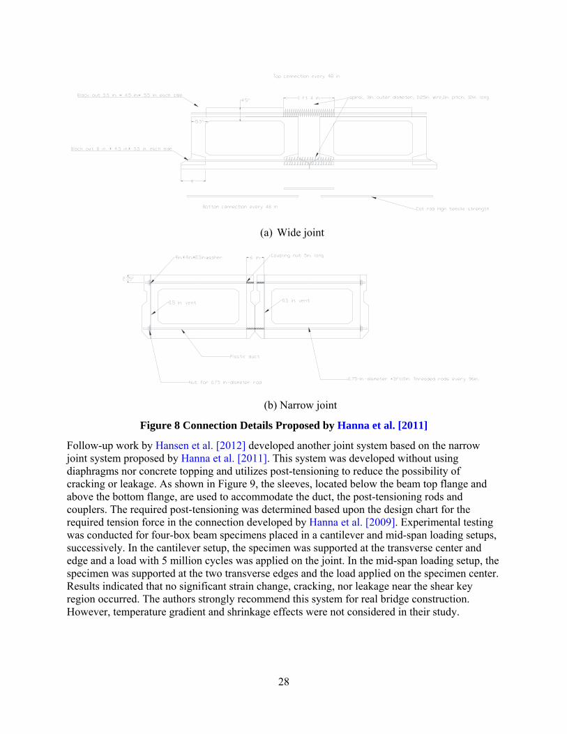
With the goal of achieving simple and economic fabrication and construction of precast adjacent box girder systems, Hanna et al. [2011] developed and evaluated two types of non-post-tensioned transverse connection details that don’t use diaphragms nor a concrete deck (i.e., the wide joint system and the narrow joint system shown in Figure 8(a) and Figure 8(b)). The two systems were developed based on the AASHTO/PCI and the Illinois DOT box beam connection details, respectively. The wide joint system incorporates a wide full-depth keyway joint filled with cast-in-place concrete and utilizes top and bottom reinforcement placed in the top and bottom flanges of the box beams to resist transverse tensile stresses. The narrow joint system incorporates a narrow joint with a partial depth keyway, top shear key and non-shrink grout and utilizes top and bottom threaded rods placed in the top and bottom flanges of the box beams to resist the transverse tensile stresses. 3D FE element models were established using shell elements for the beam flanges and webs and frame elements for the reinforcement and threaded rods. Design charts were developed for determining the needed tension force at the connection (i.e., the required amount of reinforcement or threaded rods). Two-beam specimens using the two systems were fabricated and tested under cyclic loads. Water dams were constructed on the top surface of the specimens so as to monitor for crack development and water leakage. Test results indicated that, for the two system specimens, neither cracks nor water leakage were found in the keyway after 2 million cycles and the differential deflections were found to be below 0.07 in. after 3 million cycles. However, in their study, no apparent consideration was given to performance under thermal loads.
Take Away Points:
It may be possible to design a bridge without transverse post-tensioning that performs adequately.
28
(a) Wide joint
(b) Narrow joint
Figure 8 Connection Details Proposed by Hanna et al. [2011]
Follow-up work by Hansen et al. [2012] developed another joint system based on the narrow joint system proposed by Hanna et al. [2011]. This system was developed without using diaphragms nor concrete topping and utilizes post-tensioning to reduce the possibility of cracking or leakage. As shown in Figure 9, the sleeves, located below the beam top flange and above the bottom flange, are used to accommodate the duct, the post-tensioning rods and couplers. The required post-tensioning was determined based upon the design chart for the required tension force in the connection developed by Hanna et al. [2009]. Experimental testing was conducted for four-box beam specimens placed in a cantilever and mid-span loading setups, successively. In the cantilever setup, the specimen was supported at the transverse center and edge and a load with 5 million cycles was applied on the joint. In the mid-span loading setup, the specimen was supported at the two transverse edges and the load applied on the specimen center. Results indicated that no significant strain change, cracking, nor leakage near the shear key region occurred. The authors strongly recommend this system for real bridge construction. However, temperature gradient and shrinkage effects were not considered in their study.
29
Take Away Points:
A cast-in-place topping may further improve the performance of a non-post-tensioned box beam bridge.
Figure 9 Connection Details Proposed by Hansen et al. [2012]
Grace et al. [2012] inspected a bridge in Michigan constructed based on recent Michigan design procedures. The bridge has two simply supported spans of 122.5 ft, seven diaphragms with post-tensioning bars that were highly post-tensioned before grouting, and full depth keyways with a top shear key and a concrete deck. The inspection results found that significant longitudinal cracks were formed in the shear key and deck even though the traffic on that bridge is light and was judged to not likely have induced those cracks. In addition, inspection on some other adjacent box girder bridges in Michigan also revealed that reflective cracks had formed in the deck. To investigate the source of those cracks, the authors conducted an experimental test of a bridge specimen in the lab. A four-point concentrated load up to the service load of 80 kips was applied on the specimen, and no reflective cracks in the deck were found even when the transverse post-tensioning decreased to zero. They concluded that the traffic loads are not the main condition causing reflective cracking in the deck. Thus, the authors considered temperature effects in subsequent FE analyses. The FE model was established using solid elements for the beams, diaphragms and deck, and link elements for the post-tensioning ties. After the FE model was validated against the results from the experimental tests, FE analyses of real bridges was performed considering dead and live loads and temperature gradients according to the AASHTO bridge design specifications. Based on the FE results, the required amount of transverse post-tensioning required to mitigate reflective cracking for the real bridges was then established. For practical applications, the required number of diaphragms and the required amount of post-tensioning per diaphragm were given for the adjacent box-beam bridges in Michigan. The authors found that the post-tensioning effects are mainly localized at the diaphragm regions due to shear lag effects and the required amount of diaphragms for eliminating reflective cracks increases with an increase in span length, while the required post-tensioning increases with increased bridge width. Take Away Points:
Traffic loads are not the primary factor in the development of cracks. Temperature induced effects may be the primary source of crack development.
30
4.4 Literature Search and Survey Synthesis and Summary
A significant amount of information related to adjacent box beams was presented and summarized in the preceding pages. Although there are many important facts to take-away from these sources, the following synthesis and summary was formulated to provide a brief synopsis of the information that had the greatest impact on the development of the research plan summarized in the following pages.
Cracking of the shearkey between adjacent box beams appears to principally be a service related problem as multiple sources indicate that even with a cracked joint, a bridge can continue to effectively distribute loads throughout the primary load carrying members. Consistent throughout the literature is the conclusion that joints that utilize full-depth keyways combined with a shearkey located at mid-depth perform the best. In a related manner, transverse post-tensioning seems to be the most effective when two ties are used at each location (e.g, one near the top and one near the bottom). Further, it seems apparent that bridges perform better with high amounts of transverse post-tensioning (note, however, that there have been some reported instances where no post-tensioning was reported to perform well too). Further, systems that use a structural cast-in-place deck tend to perform better over time and that the best performance tends to be derived when the reinforcement amount is rather high. However, there is some evidence to suggest that using higher post-tensioning levels may be able to compensate for not having a structural deck.
Geometrically, it may be possible that the amount of post-tensioning required on a per foot basis may be constant for bridges with variable lengths but a single width; also, skew may play a role in the amount of post-tensioning required for a given span length. For a given span length, the amount of post-tensioning required does vary with bridge width and also varies with skew.
With regard to cracking, it appears that cracking tends to be most prominent at the interface between the joint material and the box beam. Further, cracking seems to first initiate near the ends of beams. Cracking does not seem to be first initiated by the application of live loads. There are, however, differing opinions on the relative contribution to cracking from shrinkage and temperature. Nevertheless, once cracking is initiated by either shrinkage and/or temperature, they can continue to grow with subsequent live load application.
To summarize information useful for the development of the analytical and testing plans, design/construction aspects and FE analyses and testing on adjacent box beam bridges were grouped. Design and construction attributes for the adjacent box girder bridges in studies reported above are summarized in Table 4. FE analysis details are summarized in Table 5. Laboratory tests of small scale, medium scale, and full scale specimens are summarized in Table 6. Field testing of adjacent box girder bridges are summarized in Table 7. These four tables were found to be very helpful in developing the plan for the analytical and experimental evaluations. For instance, the performance of various keyway geometries have been evaluated by other researchers, including partial depth keyways and full depth keyway with (or without) top shear key, mid-depth shear key or bottom shear key as shown in Table 4. The literature search results indicated that the full depth keyways generally show better performance than partial depth keyways, and mid-depth shear keys show better performances than top and bottom shear keys. Thus, the proposed experimental and analytical studies will mainly focus on full depth keyway with mid-depth shear key.
31
Ref
s.K
eyw
ay g
eom
etri
esT
rans
vers
e T
ie
deta
ils
Dia
phra
gms
Gro
utK
eyw
ay
prep
arat
ion
Bea
ring
de
tail
sC
onst
ruct
ion
sequ
ence
Con
cret
e D
eck
FE
anal
ysis
Lab
orat
ory
test
ing
Fiel
d te
stin
g
Huc
kel
brid
ge
[199
5]Pa
rtia
l dep
th k
eyw
ay
Gird
er m
id-h
eigh
t;
Non
-pos
t-te
nsio
n m
ild s
teel
(1 in
. di
amet
er)
Yes
NG
NG
NG
NG
Non
eY
esN
oY
es
Gul
yas
et a
l. [1
995]
Fu
ll de
pth
keyw
ay a
nd to
p sh
ear k
ey; N
arro
w jo
int
No
No
Non
-shr
ink
grou
t;
MA
P m
orta
rsSa
ndbl
ast/
was
h of
fN
AN
AN
AN
oY
esN
o
El-R
emai
ly, e
t al
. [19
96]
Part
ial d
epth
key
way
and
to
p sh
ear k
ey (p
ocke
t nea
r di
aphr
agm
s)
Post
-ten
sion
ing
(det
erm
ined
by
desi
gn c
alcu
latio
ns)
5N
GN
GN
GPo
st-t
ensi
ng
afte
r gro
utin
gN
oY
esN
oN
o
Huc
kel
brid
ge
and
El-E
snaw
i [1
997]
Part
ial d
epth
key
way
and
to
p an
d m
id-d
epth
she
ar
keys
No
No
Non
-shr
ink
grou
t;
MA
P m
orta
rs;
epox
y
Pow
er g
rinde
r an
d w
ire b
rush
; sa
nd-b
last
erN
AN
AN
oY
esY
esN
o
Lal
l et a
l. [1
998]
Full
dept
h ke
yway
and
top
shea
r key
Tw
o po
st-
tens
ioni
ng ti
es a
t th
ird p
oint
s in
dep
thM
ore
than
3N
GSa
ndbl
ast,
clea
ned,
and
pre
-w
ette
d
Full
wid
th
bear
ing
NA
Yes
No
No
No
Gre
uel e
t al.
[200
0]Pa
rtia
l dep
th k
eyw
ay a
nd
mid
-dep
th s
hear
key
Non
-pos
t-te
nsio
ned
rods
5N
GN
GN
eopr
ene
bear
ing
pad
Gro
ut a
fter
in
stal
ling
rods
2.5
in. a
spha
lt w
earin
g su
rfac
eN
oN
oY
es
Mil
ler
et a
l. [1
999]
Part
ial d
epth
key
way
and
m
id-d
epth
she
ar k
ey
(Poc
ket n
ear d
iaph
ragm
s)
Slig
htly
pos
t-te
nsio
ned
rods
5N
on-s
hrin
k gr
out;
ep
oxy
NG
NG
Post
-ten
sion
ing
befo
re g
rout
ing
No
No
No
Yes
Issa
et a
l. [2
003]
Full
dept
h ke
yway
and
mid
-de
pth
shea
r key
No
No
Set 4
5; s
et 4
5 H
W;
set g
rout
; pol
ymer
co
ncre
te
Sand
blas
t; a
ir pr
essu
re a
nd
high
pre
ssur
e w
ashi
ng
NA
NA
NA
Yes
Yes
No
Bad
wan
and
L
iang
[200
7a]
Full
dept
h an
d m
id-d
epth
sh
ear k
eyB
onde
d po
st-
tens
ioni
ng te
ndon
sN
oN
GN
GN
GPo
st-t
ensi
onin
g be
fore
gro
utin
gN
oY
esN
oN
o
Bad
wan
and
L
iang
[200
7b]
Full
dept
h ke
yway
and
m
id-d
epth
she
ar k
eyB
onde
d po
st-
tens
ioni
ng te
ndon
sN
oN
GN
GN
GPo
st-t
ensi
onin
g be
fore
gro
utin
gN
oY
esN
oY
es
Don
g et
al.
[200
7]
Full
dept
h an
d m
id-d
epth
sh
ear k
ey; p
artia
l dep
th
keyw
ay a
nd m
id- (
bott
om-)
sh
ear k
ey
No
No
Yes
NG
NG
NA
No
Yes
No
No
MA
P - M
agne
sium
am
mon
ium
pho
spha
te; N
A -
Not
App
licab
le; C
FRP
- Car
bon
Fibe
r Rei
nfor
ced
Poly
mer
; NG
- N
ot G
iven
Tab
le 4
Des
ign
an
d C
onst
ruct
ion
Att
rib
ute
s
32
Ref
s.K
eyw
ay g
eom
etri
esT
rans
vers
e T
ie
deta
ils
Dia
phra
gms
Gro
utK
eyw
ay
prep
arat
ion
Bea
ring
de
tail
sC
onst
ruct
ion
sequ
ence
Con
cret
e D
eck
FE
anal
ysis
Lab
orat
ory
test
ing
Fiel
d te
stin
g
Sha
rpe
(200
7)
Part
ial d
epth
key
way
and
to
p sh
ear k
ey; F
ull d
epth
ke
yway
and
top
shea
r key
Unb
onde
d po
st-
tens
ioni
ng te
ndon
sSp
aced
at 1
0 ft
Non
-shr
ink
grou
tN
GEl
asto
mer
ic
bear
ing
pads
NG
Yes
Yes
No
No
Att
anay
ake
and
Ak
tan
(200
8)
Full
dept
h ke
yway
and
to
p sh
ear k
ey (1
.5-3
in.)
Bon
ded
post
-te
nsio
ning
tend
ons
6
Typ
e R
-2, w
hich
is
cem
ent a
ndfin
e ag
greg
ate
mix
ture
with
14
+/-
4% a
ir
NG
NG
Post
-ten
sion
ing
afte
r gro
utin
gY
esN
oN
oY
es
Kim
et a
l. (2
008)
FEA
: Ful
l dep
th k
eyw
ay
and
no, t
op, m
id-d
epth
or
bott
om s
hear
key
s
Tes
t: Fu
ll de
pth
and
mid
-de
pth
shea
r key
s (2
-4.8
in.)
Bon
ded
post
-te
nsio
ning
tend
ons
5C
ast-
in-p
lace
co
ncre
teN
GEl
asto
met
ric
rubb
er p
adN
GY
esN
oN
oY
es
Att
anay
ake
and
Ak
tan
(200
9) a
nd
Ulk
u et
al.
(201
0)
Full
dept
h ke
yway
and
to
p sh
ear k
ey (1
.5-3
in.)
Unb
onde
d po
st-
tens
ioni
ng te
ndon
s5-
7N
GN
GN
G
Mul
ti-st
aged
co
nstr
uctio
n:
Post
-ten
sion
ing
afte
r gro
utin
g an
d af
ter d
eck
plac
emen
t
Yes
Yes
No
No
San
g (2
010)
Fu
ll de
pth
keyw
ay a
nd to
p sh
ear k
ey; P
artia
l dep
th
and
top
shea
r key
Post
-ten
sion
ing
tend
ons
NG
Fibe
r rei
nfor
ced
cem
emtit
ious
m
ater
ial;
cem
emtit
ious
m
ater
ial;
epox
y
NG
Plac
ed u
nder
th
e ke
yway
Post
-ten
sion
ing
afte
r gro
utin
gY
esY
esY
esN
o
Fu e
t al.
(201
1)
Full
dept
h ke
yway
and
top
shea
r key
Post
-ten
sion
ing
thre
aded
rods
No
Non
-shr
ink
grou
tN
GN
GPo
st-t
ensi
onin
g be
fore
gro
utin
gY
esY
esN
oY
es
Han
na e
t al.
(201
1)
Full
dept
h ke
yway
and
no
shea
r key
; Par
tial d
epth
an
d to
p sh
ear k
ey
Non
-pos
t-te
nsio
ning
re
info
rcem
ent;
Non
-po
st-t
ensi
onin
g th
read
ed ro
ds
No
Cas
t-in
-pla
ce
conc
rete
; Non
-sh
rink
grou
tR
ough
ened
NG
NA
No
Yes
Yes
No
Jenn
a et
al.
(201
2)Pa
rtia
l dep
th k
eyw
ay a
nd
top
shea
r key
Non
-pos
t-te
nsio
ning
thre
aded
ro
dsN
oN
on-s
hrin
k gr
out
Rou
ghen
edN
eopr
ene
bear
ing
pad
Post
-ten
sion
ing
afte
r gro
utin
gN
oN
oY
esN
o
Gra
ce e
t al.
(201
2)
Full
dept
h ke
yway
and
top
shea
r key
Unb
onde
d po
st-
tens
ioni
ng C
FRP
From
FEA
Non
-shr
ink
grou
tN
GN
eopr
ene
bear
ing
pad
Post
-ten
sion
ing
afte
r gro
utin
gY
esY
esY
esN
o
CFR
P - C
arbo
n Fi
ber R
einf
orce
d Po
lym
er; M
AP
- Mag
nesi
um a
mm
oniu
m p
hosp
hate
; NA
- N
ot A
pplic
able
; N
G -
Not
Giv
en
Tab
le 4
Des
ign
an
d C
onst
ruct
ion
Att
rib
ute
s (C
onti
nu
ed)
33
Table 5 Summary of FE Analysis
Refs.Type of
AnalysisSoftware
Box Beam
Keyway Interface Diaphragm Deck Tie Bearing Load
Huckelbridge (1995)
NG NG NG NG NG NG NG NG NG NG
El-Remaily, et al. (1996)
Grillage analysis NGBeam
elementsCommon
nodesCommon
nodesbeam
elementsNone NA
Simply supported
Dead and live loads
(including
3D SAPSolid
elementsSolid
elementsCommon
nodesSolid
elementsNone
Directly apply forces
Simply supported
Concentrated load
2D SAPPlane
elementsPlane
elementsCommon
nodesNone None None
Spring elements
Concentrated load
Issa et al. (2003)
3D ANSYSSolid
elementsSolid
elementsCommon
nodesNone None None NA
Concentrated load
Badwan and Liang (2007a)
Grillage analysis ANSYSBeam
elementsCommon
nodesCommon
nodesBeam
elementsNone NA
Simply supported
HS-25 truck
Badwan and Liang (2007b)
3D ANSYSSolid
elementsSolid
elementsCommon
nodesNone None
Link element
Simply supported
Dump truck
Dong et al. (2007)
3D ABAQUSSolid
elementsSolid
elementsCommon
nodesNone None None NA
Concentrated load
Sharpe (2007)
3D ANSYSSolid
elementsSolid
elementsCommon
nodesSolid
elementsSolid
elementsNone
Spring elements
HS-25 truck; shrinkage;
thermal
2D DIANAPlane
elementsPlane
elementsCommon
nodesNone None None
Simply supported
Concentrated load
3D DIANASolid
elementsSolid
elementsCommon
nodesSolid
elementsSolid
elementsBar
elementsSimply
supportedConcentrated
load
Attanayake and Aktan
(2009)
Maromechanical model
Programming
Integrated Plate
elements
Integrated Plate
elementsNONE None
Integrated Plate
elementsNone
Simply supported
HL-93
Ulku et al. (2010)
3D ABAQUSSolid
elementsSolid
elementsNONE
Solid elements
Solid elements
Truss elements
Simply supported
HL-93
Grillage analysis NGBeam
elementsCommon
nodesCommon
nodesBeam
elementsNone NA
Simply supported
HS-25 truck
2D ABAQUSPlane
elementsPlane
elementsCommon
nodesNone None None NA
Concrentratd and
distributed
Hanna et al. (2011)
3D SAP2000Shell
elementsCommon
nodesCommon
nodesNone None
Frame elements
Simply supported
HL-93
Fu et al. (2011)
3D ANSYSSolid
elementsSolid
elementsContact elements
None NoneLink
elementsSimply
supportedHL-93
Grace et al. (2012)
3D NGBrick
elementsBrick
elementsContact elements
Brick elements
Brick elements
Truss elements
Simply supported
HL-93 and temperature
gradient
Huckelbridge and El-Esnawi
(1997)
Kim et al. (2008)
Sang (2010)
NG - Not Given; NA - Not Applicable
34
Ref
eren
ces
Tes
ting
sc
ale
Spe
cim
ens
Len
gth
Sk
ewW
idth
Dep
thN
umbe
r of
bea
ms
Gro
ut s
tren
gth
Con
cret
e st
reng
thL
oad
Tem
pera
ture
R
elat
ive
disp
lace
men
tS
trai
n C
rack
de
test
ion
Gul
yas
et a
l. (1
995)
Sm
all
scal
eK
eyw
ay
spec
imen
s3.
25 in
.N
A6-
6.5
in.
7-14
in.
NA
Non
-shr
ink
grou
t: 5.
9;
M
AP
mor
tars
: 7.3
ksi
NG
Ver
tical
she
ar;
Dire
ct te
nsio
n;
Long
itudi
nal
shea
r
No
NA
NA
Vis
ually
Huc
kel
brid
ge
and
El-E
snaw
i (1
997)
Smal
l sc
ale
Mul
tu-
beam
slic
es12
in.
0º14
433
in.
3N
on-s
hrin
k gr
out:
5.5
ksi;
M
AP
mor
tars
: 5 k
si;
epox
y: 1
3 ks
i6
ksi
Cyc
lic
conc
entr
ated
load
No
Dire
ct C
urre
nt
Diff
eren
tial
Tra
nsdu
cer
(DC
DT
)
Foil-
back
ed
stra
in
gage
s
Vis
ually
Issa
et a
l. (2
003)
Smal
l sc
ale
Key
way
sp
ecim
ens
5-6
in.
017
-21
in.
17-2
6 in
.N
A
Set 4
5: 5
.8 k
si;
set 4
5 H
W: 5
.6 k
si;
set g
rout
: 7.7
ksi
;
poly
mer
con
cret
e:10
.8 k
si
6.5
ksi
Dire
ct s
hear
; D
irect
tens
ion;
Fl
exer
al b
endi
ngN
oN
GN
GV
isua
lly
Kim
et a
l. (2
008)
Fu
ll sc
ale
Mul
ti-bo
x be
am
spec
imen
s61
ft0
95 in
.31
.5 in
34.
9 ks
i8
ksi
Stat
ic
com
cent
rate
d lo
ad/ C
yclic
co
ncen
trat
ed lo
ad
(Mid
-spa
n)
No
Line
ar
varia
ble
diff
eren
tial
tran
sduc
ers
(LV
DT
s)
Stra
in
gaug
esV
isua
lly
San
g (2
010)
Sm
all
scal
eK
eyw
ay
spec
imen
s5
in.
07
in.
17 in
.N
AC
emen
titio
us g
rout
: 4.5
ks
i;
e
poxy
: 10
ksi
11.3
Dire
ct s
hear
No
NG
NG
Vis
ually
Han
na e
t al.
(201
1)
Med
ium
sc
ale
Mul
ti-bo
x be
am
spec
imen
s8
ft0
8 ft
27 in
.;
32 in
.2
6 ks
i8
ksi
Cyc
lic
conc
entr
ated
load
No
Yes
No
A w
ater
da
m
Jenn
a et
al.
(201
2)M
ediu
m
scal
e
Mul
ti-bo
x be
am
spec
imen
s8
ft0
16 ft
27 in
.4
Non
-shr
ink
grou
t: 10
ksi
8 ks
iC
yclic
co
ncen
trat
ed lo
adN
oY
esN
oA
wat
er
dam
; V
isua
lly
Gra
ce e
t al.
(201
2)
Full
scal
e
Mul
ti-bo
x be
am
spec
imen
s20
ft0
75 in
.14
in.
4Lo
w-s
hrin
k gr
out:
8 ks
iB
eam
: 6 k
si;
Dec
k: 5
.7 k
si
Serv
ice
conc
entr
ated
load
up
to 8
0 ki
ps
No
(Rec
ogni
ze
impo
rtan
ce o
f te
mpe
ratu
re
effe
cts)
NG
No
Vis
ually
NG
- N
ot G
iven
; NA
- N
ot A
pplic
able
Tab
le 6
Su
mm
ary
of L
abor
ator
y T
esti
ng
35
Ref
eren
ces
Bri
dge
Num
ber
of S
pan
Spa
n (f
t)S
kew
(d
egre
e)W
idth
(f
t)
Num
ber
of
beam
s
Bea
m
wid
th ×
dept
h (i
n.)
Gro
ut
stre
ngth
Con
cret
e st
reng
th
(ksi
)T
empe
ratu
reL
oad
Rel
ativ
e di
spla
cem
ent
Str
ain
Cra
ck
dete
ctio
n
No.
11
32.5
2044
1148
× 1
7N
G
No.
24
40/5
4/54
/40
17.4
6817
48 ×
27
NG
Mil
ler
et a
l. (1
999)
4 (w
ith
sam
e gi
rder
s,
diff
eren
t gr
outin
g)
175
016
448
× 3
35
ksi
Bea
m: 9
.4
Yea
ly ra
nge:
-10
-100
ºF;
sum
mer
: 50-
90
ºF
20 k
ips
on th
e lo
aded
inte
rior
beam
Dire
ct C
urre
nt
Diff
eren
tial
Tra
nsdu
cer
(DC
DT
)
Tra
nsve
rse
omeg
a cl
ip
gaug
es;
vibr
atin
g w
ire g
auge
Ultr
ason
ic
puls
e ve
loci
ty
Gre
uel e
t al.
(200
0)
11
115.
50
4812
48 ×
42
NG
Bea
m: 1
0N
GO
hio
DO
T tr
uck
sim
ilar t
o H
S-20
T
ruck
Line
ar
varia
ble
diff
eren
tial
tran
sfor
mer
(L
VD
T)
Vib
ratin
g w
ire g
auge
; fo
il st
rain
ga
ges;
NG
Bad
wan
and
L
iang
(2
007b
) 1
229
/29
3044
687
× 1
5-18
NG
NG
NG
29 k
ips
dum
p tr
uck
(9+2
0 ki
ps)
No
Stra
in
tran
sduc
erN
G
Att
anay
ake
and
Ak
tan
(200
8)
12
79/7
90
93.5
2248
× 3
3N
GD
eck:
6.4
Early
sum
mer
No
No
No
Vis
ually
Kim
et a
l. (2
008)
1
243
/43
539
1430
× 3
1.5
4.4
ksi
Bea
m: 7
.3N
G77
.2 k
ips
dum
p tr
uck
(16.
7+60
.5
kips
)
Line
ar
varia
ble
diff
eren
tial
tran
sduc
ers
Stra
in
gaug
esV
isua
lly
Gra
ce e
t al.
(201
2)
11
35 ft
033
1136
× 1
5N
GB
eam
: 7.0
; D
eck:
4N
G35
kip
s du
mp
truc
k (1
0.8+
24.2
ki
ps)
No
Stra
in
sens
orN
G
Vib
ratin
g w
ire g
age
Vis
ually
Huc
kel
brid
ge
et a
l. (1
995)
NA
NA
50 k
ips
Dum
p tr
uck
(12
+38
kips
)
Rel
ativ
e di
spla
cem
ent
tran
sduc
ers
(Ow
n m
ade)
NG
- N
ot G
iven
; NA
- N
ot A
pplic
able
Tab
le 7
Su
mm
ary
of F
ield
Tes
tin
g
36
5. Updated Work Plan
5.1 Experimental and Analytical Evaluations
5.1.1 Introduction
To meet the overall project goal which results in an adjacent box beam bridge that is crack and leak-free while at the same time meeting individual project goals (e.g., investigating cracking, etc.), a modified work plan has been developed and is described here. Although the fundamentals of the original project RFP, proposal, and work plan remain, the plan described below, in short, proposes to complete the analytical and experimental programs by alternating between them in an attempt to leverage information learned before proceeding to other interdependent steps. The experimental and analytical evaluation program activities have been developed with the specific goals of investigating cracking in adjacent box beam bridges, improving the cracking resistance and behavior of adjacent concrete box beams connection details, and eliminating cracking and leakage in the keyways between beams. Note that the cracks of primary concern in this work consist of longitudinal cracks in the keyways between adjacent box beams, which can cause serviceability issues (but tend to not degrade lateral load distribution characteristics). Based upon Table 4, the design and construction attributes influencing the long-term performance of these bridges include: (1) keyway geometry and preparation (including the use of shear keys), (2) joint material characteristics (including the influence of curing conditions), (3) bearing details, (4) use (or lack of use) of a cast-in-place concrete deck, (5) amount and location of transverse post-tensioning and diaphragms, and (6) construction sequence. Based upon the results of the literature search, the survey of states, and our own experiences, it seems clear that the primary loads causing cracks in the joints between adjacent box beams are the result of early age shrinkage effects, temperature effects, and live loads. Obviously the influence of these loading conditions must be considered such that the most critical cases are considered in the evaluation programs.
In previous research, four commercially available software packages (i.e., SAP2000, ANSYS, ABAQUS, and DIANA), were used to investigate keyway performance and cracking in adjacent box beam bridges (see Table 5). Although it is hard to determine if one software package outperforms the others, the key to deriving reasonable analytical results is to use appropriate FE modeling techniques. Due to previous extensive experience, the software ANSYS will be used in this project to develop the nonlinear FE models for the analytical evaluation program. ANSYS is a computationally advanced analytical software package that allows for the simulation of most any structural engineering problems through proper application of FE modeling techniques. In constructing the models, proper and appropriate material properties and element types within ANSYS will be selected and utilized for establishing different bridge components (including nonlinear effects).
The experimental and analytical evaluation programs will be conducted through nine, linear steps with the objectives as follows:
Step A: The objective is to collect time-dependent material properties, including properties resulting from variable curing methods, and select the most viable joint material and keyway preparation options based upon: (1) tensile strength, (2) interfacial bond strength, and (3) shrinkage characteristics.
37
Step B: The objective is to experimentally investigate cracking (and collect information for validation of FE modeling approaches) in longitudinal joints by conducting small scale tests of: (1) early age crack development and (2) effectiveness of post-tensioning for crack closure prior to live loading.
Step C: The objective is to validate nonlinear, time-dependent FE modeling approaches for predicting cracking in keyways and crack closure due to post-tensioning.
Step D: The object is to use the validated FE model to analytically investigate cracking in bridges with variable: lengths, widths, skews, post-tensioning details, diaphragm designs, differential cambers, and keyway geometry subjected to early age shrinkage.
Step E: The objective is to experimentally study the influence of shear key geometry on joint behavior under early age shrinkage and live loads (e.g., AASHTO HL-93 loading).
Step F: The objective is to validate FE modeling approaches for predicting the behavior of joints with different shear key geometries under shrinkage and live loads.
Step G: The objective is to design a crack free bridge based upon experimental results and validated FE modeling techniques resulting from Steps A-F that will be tested and evaluated in Step H.
Step H: The objective of this step is to fabricate and test two full scale specimens and validate the FE models against experimental results.
Step I: The objective of this step is to determine the required post-tensioning and other details that result in crack free bridges by considering different span lengths, bridge widths, and skews via a parametric study using the validated FE models.
A typical/common box beam cross-section used by multiple State Departments of Transportation is illustrated in Figure 10. The basic dimensions of the box beam section and details for prestressing strands, mild longitudinal reinforcement, stirrups, and ducts are all conceptually shown in Figure 10. The basic box beam configuration shown in Figure 10 will be used throughout the analytical and experimental work described in the following pages. The test specimens described in the subsequent sections will have the basic cross-section shown in Figure 10, with the specific number of presstressing strands as designed for a 45 ft span adjacent box beam bridge (based on AASHTO LRFD bridge design specifications). In the analytical evaluation, the number of strands and dimensions of box beams of the bridges with other span up to 100 ft will be designed and updated based upon the AASHTO LRFD bridge design specifications. Note, that for clarity details and information regarding the shear key and keyway configuration have been omitted in Figure 10 as those details will be established in the various steps described below.
38
Figure 10 Typical Box Beam Cross-section
5.1.2 Collection of Material Properties and Selection of the Joint Material and Keyway Preparation
Step A – Material Testing and Selection
The objective of Step A is to collect time-dependent, nonlinear material properties, including properties resulting from variable curing methods, and select the most viable joint material and keyway preparation options based upon: (1) tensile strength, (2) interfacial bond strength, and (3) shrinkage.
Initial basic material testing and characterization will be conducted to measure and quantify: (1) shrinkage and (2) tensile strength of various joint materials at 28 days as shown in Table 8. During initial material characterization, the following joint materials will be tested (note these materials have been selected based upon the results of the literature review and consultation with bridge owners and material specialists): epoxy grout and non-shrink grout for use in the Type IV keyway; fiber reinforced concrete, ultra-high performance concrete (UHPC) and cast-in-place (CIP) concrete formulated with Type K cement for use in the Type V key (Type IV and Type V keyway are as generically shown in Figure 1). For materials placed in joints between adjacent box beams, the principal environmental factor impacting curing is the ambient temperature during curing (especially during early age curing). Given the fact that joint materials are typically only placed during certain temperature ranges, initial testing will evaluate the basic properties after the specimens have been cured at two temperatures: room temperature and at approximately 55 ºF. After conducting the initial joint material characterization tests, the best joint material for use in a Type IV keyway and a Type V keyway will be selected.
The interfacial bond strength between the box beam concrete and the two joint materials selected above will be evaluated considering two types of keyway preparations (i.e., powerwashed and mechanical roughened) as shown in Table 9. Curing of the specimens will occur at room temperature due to the fact that temperature has little influence on interfacial bond strength.
39
After conducting the interfacial bond strength testing, the best keyway preparation approach will be selected.
Based upon the initial basic material test results, the most promising joint materials and keyway preparation will be selected. Then, time-dependent material testing will be conducted to characterize the nonlinear changes in shrinkage, bond strength, and tensile strength with time (e.g., at 1 day, 7 days, 14 days, and 28 days) as shown in Table 10. These measured time-dependent, nonlinear material characteristics will be extensively utilized in the nonlinear FE simulations conducted in subsequent steps.
Table 8 Initial Joint Material Property Testing
Materials Curing Properties
Epoxy grout; non-shrink grout (Joint materials for Type IV keyways)
Room temperature (a) Tensile
strength; (b) Shrinkage ~55ºF
Fiber reinforced concrete, UHPC, cast-in-place concrete with Type K cement (Joint material for Type V keyways)
Room temperature (a) Tensile
strength; (b) Shrinkage ~55ºF
Table 9 Keyway Interface Preparation Testing
Material Keyway Preparations
Curing Property
Most viable Type IV and Type V joint materials
Powerwashed Room temperature
Interfacial bond strength Mechanical
roughened
Table 10 Time Dependent Material Property Testing
Material Curing Properties Box beam concrete
Room temperature
Compressive strength; tensile strength
Joint material (Most viable Type IV and Type V joint materials)
Room temperature
Compressive strength, tensile strength, shrinkage
Keyway interface (Most viable Type IV and Type V joint materials and the best keyway preparation)
Room temperature
Interfacial bond strength
40
5.1.3 Crack Development and Resistance Investigation using Small-Scale Testing and FE Simulations
Step B – Small Scale Testing
If early age cracks form in the keyway between adjacent box beams they primarily form due to shrinkage which is sometimes referred to as temperature shrinkage, autogeneous shrinkage, and/or drying shrinkage. This shrinkage is due to many factors including temperature during curing, loss of water, and chemical reactions occurring during the hydration process. The crack resistance of the keyway is dependent upon both the material characteristics and several bridge details.
In step B, the objective is to experimentally investigate cracking (and collect information for validation of FE modeling approaches) in the longitudinal joints by conducting small scale tests of: (1) early age crack development and (2) the effectiveness of post-tensioning at closing cracks prior to live load application. Note that during Step B the most viable Type IV and Type V joint materials and the most viable keyway preparation identified in Step A will be utilized in the keyways. Further, to preliminarily investigate the effectiveness of post-tensioning at closing cracks developed during early age curing, post-tensioning will be applied after early age crack development has been investigated and documented.
To complete Step B, small scale specimens consisting of two box beam sections will be fabricated, instrumented, and tested in the Iowa State University Structural Engineering Laboratory. The specimens will consist of two, side-by-side 2 ft long box beam sections (recall the basic geometry mentioned previously). Two types of keyway geometries (i.e., the Type IV and Type V as shown in Figure 11) will be evaluated. Due to material placement limitations associated with the geometric width of the keyways, the materials selected during Step A will in some ways drive the specific material/geometry combination. For example, epoxy grout and non-shrink grouts would be used with the Type IV keyway and fiber reinforced concretes, UHPC, and CIP concrete with Type K cement would be used with the Type V keyway. Again, the materials and keyway preparation utilized will be based upon the results from the material testing and selection process described in Step A.
(a) Type IV (b) Type V
Figure 11 Small Scale Specimen Keyway Geometries (all units are inches)
41
Table 11 Small Scale Specimens
Keyway geometry
Joint materials Keyway preparation
Type IV
Either epoxy grout or non-shrink grout based upon Step A results
Either power washed or mechanical roughened based upon Step A results
Type V Either fiber reinforced concrete, UHPC, or CIP concrete with Type K cement based upon Step A results
Either power washed or mechanical roughened based upon Step A results
The specimens will be constructed in two stages which fundamentally replicate the way adjacent box beam bridges are constructed: the first stage is to fabricate the box beam sections and the second stage is to place the joint material in the keyway. In the first step, the basic box beam sections will be formed (including the interior void) using typical concrete forming techniques. Prestressing strands, mild longitudinal reinforcement, stirrups, and ducts will be placed as shown in Figure 12 (using the basic box beam geometry shown in Figure 10). Note that the specific number of strands will be based the basic design for a 45 ft span adjacent box beam bridge (based upon AASHTO LRFD bridge design specifications). In the second step, the box beam sections will be placed side-by-side as shown in Figure 12 and Figure 13. Note that during placement and curing of the joint material, the individual box beam sections will be restrained from moving by applying a vertical “tie-down” force over the webs which are away from the joint of interest (described in greater detail subsequently). Before placing the joint material, the post-tensioning ties will be inserted into the ducts as shown in Figure 12. However, no post-tensioning will be applied at this stage.
Figure 12 Basic Configuration for Step B Testing
During the early age-curing period, vertical restraining forces (as shown in Figure 14 which induce a lateral frictional force between the box beams and the laboratory floor) will be applied to simulate the transverse restraint provided by the bearings and other box girders. In this configuration, the interaction of the two materials will be able to be discretely observed.
Post-tensioning ties
Dished plate and chuck Keyway
42
Following placement of the joint material, the material will be cured for 7 days. During curing, cracking will be investigated in the following ways: (1) displacement transducers will be mounted at the top of the keyway joint to measure any horizontal separation at the keyway-box beam interface; (2) the formation of cracks during curing will be documented every 12 hours using visual crack mapping techniques with crack widths measured and recorded.
After 7 days of curing, the specimen will be released from the vertical tie down forces and post-tensioning will be applied as shown in Figure 14. For comparison purposes, the horizontal relative displacement at the keyway-box beam interface will again be measured using the previously mentioned displacement transducers. In addition, to measure strain changes in the keyway and over the keyway-box beam interface during post-tensioning, strain transducers will be installed at the top, mid-depth and bottom of the box beam cross-section as shown in Figure 14. To further investigate crack closure after post-tensioning, a water dam will be placed on the top of the specimen and any observed leakage will be documented. An additional crack map survey will be conducted after post-tensioning to document any visually apparent cracks in the joint material or at the keyway-box beam interface.
Figure 13 Small Scale Specimen Test Setup During Curing
Tie down frame
(a) Side view
(b) Top view
Tie down frame
Tie down rod
Displacement transducer
Displacement transducer
43
Figure 14 Small Scale Specimen Test Setup during Post-tensioning
Step C – FE Element Simulations of Shrinkage Crack Formation and Closure
The objective of Step C is to develop and validate nonlinear, time-dependent FE modeling approaches for predicting cracking in keyways and crack closure due to post-tensioning. To accomplish this, nonlinear FE models of the Step B small scale specimens will be established and validated against the experimental results obtained in Step B. The nonlinear, time dependent material properties obtained in Step A will be utilized in the creation of the FE models. Note that cracking experimentally observed and/or measured during curing and the experimentally observed and/or measured crack closure during post-tensioning will both be compared with those from the FE models as part of the validation and investigation of cracking process.
Two types of FE models (Type A and Type B) will be used to investigate cracking and crack closure in the keyway, respectively. The Type A model will take advantage of the crack prediction capability of the ANSYS SOLID65 element. Once cracking in the keyway is well predicted using the Type A model, the Type B model will be used to simulate crack closure after post-tensioning. It should be noted that in the Type B model, contact elements will be assigned at the crack interfaces identified from the results of Step B and the results from analyses with the Type A models.
To investigate the cracking mechanism during curing, Type A models will be established. The Type A model is a nonlinear, time-dependent FE model established using ANSYS in the
(a) Side view
(b) Top view
Displacement transducer
Strain transducer
Displacement transducer
Strain transducer
44
following ways. The concrete portions of box beams and keyways will be modeled using brick elements – SOLID65. During the simulations, the keyways will be connected to the beams at common nodes. All internal reinforcement will be modeled by defining the reinforcement ratios in those elements by taking advantage of the reinforcing-bar simulation capability of the SOLID65 element. The pre-stress induced by the prestressing strands will be ignored because the behavior of interest is transverse (and the specimens have limited length); however, the stiffness of strands will be considered as part of the reinforcement ratio capability of the SOLID65 element. The shrinkage strain will be simulated by applying an artificial temperature change on the solid elements, which can be expressed as
ΔTsh = εsh/α (1)
where, ΔTsh = artificial temperature change; εsh = the desired shrinkage strain; and α = the coefficient of thermal expansion.
The nonlinear, time-dependent shrinkage properties of the concrete and the joint material used in the FE model will be as determined from the basic material property testing conducted in Step A. As a first approximation, uniform shrinkage will be applied to the FE models to check if cracking and other behaviors can be well predicted through comparison with the experimental results. It may be necessary to apply non-uniform shrinkage distributions (i.e., non-uniform ΔTsh) to better predict the crack behavior of the keyway. Other time dependent material properties including the tensile strengths of the concrete and joint materials, and the bond at the interface will be assigned as obtained from our basic material testing conducted in Step A.
When creating the Type A models, the crack capability of the SOLID65 element will be activated. The assigned maximum tensile stress in the concrete, the joint material, and at the keyway interfaces will be equal to the tensile strength of the joint material, the tensile strength of the concrete, and the bond strength at the interfaces determined in Step A. The comparisons of cracking observed experimentally and analytically will include, but will not necessarily be limited to, the time when the cracks form and the location of the cracks. Also any horizontal separation at the keyway-box beam interface observed experimentally will be compared to the results of the FE analysis. If needed, the modeling methodology will be modified until good agreement exists between the experimental and analytical results. Through these comparisons the nonlinear FE models for predicting early age shrinkage cracking will be calibrated.
Once the primary cracking interfaces are identified from the Type A models as well as the experimental testing, Type B models will be established to simulate crack closure occurring during post-tensioning. In the Type B models the transverse post-tensioning ties will be modeled using truss elements – LINK8. The post-tensioning ties will be modeled to share common nodes with the box beam elements at the contact interfaces. To model the post-tensioning forces, the concept of a temperature change will be used for the truss elements – this approach is known to be effective at simulating prestressing/post-tensioning forces. All portions of box beams and keyways will still be modeled using brick elements – SOLID65. At the non-cracking interfaces, the keyways will be connected to the beams at common nodes. At the cracking interface(s), 3-D contact elements (CONTA173 and CONTA174) will be used to model the interaction at the interface. Parameters such as the normal penalty stiffness factor (FKN), the penetration tolerance factor (FTOLN), and the coefficient of friction will be input to allow compressive stress and friction to develop at the cracking interface A cohesive zone material model will be defined for the contact elements to simulate debonding at the cracking interface. The maximum debonding
45
stress for the contact element is equal to the lesser of the tensile strength of the concrete, the tensile strength of the joint material and the bond strength between the two. Shrinkage will be then applied to the FE models to simulate the crack openings during curing. Then simulation of the post-tensioning will then be conducted to simulate crack closure until compressive stresses are generated at the interfaces. The compressive stress contours will be plotted to check their distribution of the post-tensioning force. The predicted crack closure from the Type B model will be compared to that observed during the small scale testing. Again, strains in the keyway and horizontal separation at the keyway found in the specimens and FE models will also be compared and modifications to the modeling methodology made, if necessary. 5.1.4 Investigation of Cracking in Bridges with Variable Attributes
Step D: FE Simulations of Cracking in Bridges
The objective of Step D is to use the validated FE modelling approach to analytically investigate cracking in adjacent box beam bridges with variable lengths, widths, skews, post-tensioning details, diaphragm designs, differential cambers, and keyway geometry during bridge service life.
Based upon the current AASHTO LRFD bridge design specifications, adjacent box beam bridges need to be designed to satisfy both the ultimate strength design and service strength design criteria. For these design considerations, the load combinations and load factors are well described in the AASHTO LRFD bridge design specifications. However, as the objective of this work ultimately results in the development of a crack-free bridge it seems clear that, although typically thought of as a serviceability criteria, that the bridge should remain crack-free to the ultimate load state. Thus, work in Step D will investigate cracking in bridges with variable attributes when applied loads are multiplied by applicable load factors. Note also that although all loads must globally be considered during design, here, only those loading conditions known to induce cracking in the longitudinal joint need be considered. Thus, loads such as beam dead load (note dead load due to the barrier will be considered as this results in an asymmetric loading condition), which acts on the primary elements before the joint material is placed, will not be considered and the primary focus will be on: (1) early age crack development resulting from shrinkage, (2) cracking resulting from temperature changes, and (3) cracking resulting from live loads.
To investigate cracking in Step D, FE simulations will be performed with the FE models of the bridges established taking advantage of the validated FE modelling approach developed in Step C. The concrete portions of the box beams, diaphragms, keyways, and barrier (when applicable) will be modeled using brick elements – SOLID65. The beams will be connected to the diagrams and the barriers (when applicable) by sharing common nodes. Initially, the keyways will be connected to the beams using the Type A modelling techniques described above in Step C. Once the primary cracking interface is identified from the preliminary model, contact elements will be assigned at the cracking interface, (again, following the validated Type B modelling techniques described in Step C). All internal reinforcement and presstressing strands will be modeled by defining the reinforcement ratios in those elements by taking advantage of the reinforcing-bar simulation capability of the SOLID65 element. When considered, differential cambers will be simulated by assigning misalignment(s) of the shear keys in adjacent beams. Bearing conditions will be modeled using horizontal and vertical springs, with the respective stiffnesses determined
46
based on typical material properties. The transverse post-tensioning ties will be modeled using truss elements – LINK8. The post-tensioning ties will be modeled to share common nodes with the box beam elements at the contact interfaces. And, as before, to model the post-tensioning forces, the concept of a temperature change will be used for the truss elements.
The FE models will consider the loading conditions experienced at different stages of bridge life. Based upon the AASHTO LRFD bridge design specifications there are three important stages which should be considered:
Stage 1 – Girder fabrication and erection: misalignment of shear keys can result from differential cambers caused by prestressing effects (note this stage will be considered by geometrically varying the location of the shear keys in adjacent beams);
Stage 2 – Joint material early age creep and transverse post-tensioning application; Stage 3 – In-service loadings consisting of barrier loads, live loads, temperature gradient
effects, and shrinkage effects while in service.
During stage 1 differential camber can be induced. The primary impact of this differential camber on adjacent box beam bridge performance is that it causes misalignment of the keyways. The misalignment of keyways will be geometrically simulated to study the impact of differential camber on crack formation and crack resistance.
At stage 2, the bridge system consists of the box beams, keyways, post-tensioning ties and diaphragms. During stage 2 there are two important loading effects: shrinkage of the joint material and the transverse post-tensioning. To study these, shrinkage effects will be considered first by simulating the behavior of the system through the first 7 days of curing. Next the transverse post-tensioning will be applied. Subsequently, additional shrinkage that occurs for the following 21 days will be considered.
To evaluate early-age shrinkage, the material properties measured during Step A and the validated modelling approach developed in step C will be utilized. Shrinkage strains after grouting the keyways will then be assigned to the model elements to investigate cracking in the keyways. The shrinkage strains will be estimated using the approaches validated with the small scale test results and the small scale FE simulations completed in Step C. After 7 days of curing, the post-tensioning will be analytically applied to the post-tensioning ties. If cracks were observed to develop during the first 7 days, the effectiveness of the post-tensioning at closing the cracks will be specifically observed. After the post-tensioning is applied, any additional shrinkage of the joint material occurring will be simulated. As before, crack development during this period will be of interest.
During stage 3 the barrier rail is added and the bridge is subjected to live loads and temperature changes. First, the barriers will be added to the bridge models (both in terms of dead load and stiffness) and the impact on cracking will be investigated. To apply live loads present during stage 3, the AASHTO design load HL-93 will be applied on the bridge models considering different longitudinal and transverse positions. This systematic live load placement will ensure that worst case scenarios can be fully captured. The temperature gradients present during stage 3 will be assigned to the model elements using the temperature profiles specified by the AASHTO LRFD bridge design specifications. Three different temperature induced conditions will be analytically investigated. First, uniform temperature changes will be applied. Second, top-to-
47
bottom differential temperatures will be applied. Finally, side-to-side differential temperatures will be applied. Considering all of the loadings, the individual contribution to internal stresses and the superposition of multiple loading scenarios can be studied.
One obvious way to study the effectiveness of various post-tensioning schemes is by observing the compressive stress contours in the keyways after post-tensioning (and after additional curing of the joint material). These stress contours will be especially useful as the attributes affecting the distribution of post-tensioning are studied as shown in Table 12. Many researchers [Ulku, et al. 2010; Grace et al. 2012] have shown that post-tensioning effects are mainly localized at the diaphragm regions due to shear lag effects. Further, Hansen et al. [2012] showed the potential adequacy of a post-tensioned box beam system developed without diaphragms. Thus, to evaluate the influence of the diaphragms on the post-tensioning distribution, two types of diaphragm designs will be studied (i.e., Design I: diaphragms with ties and Design II: no diaphragm). To determine the required number of ties per unit bridge length, three longitudinal distributions of post-tensioning ties will be investigated as shown in Table 12 (i.e., 5 ft, 10 ft, and 25 ft). To determine the required number of ties per cross-section, two types of vertical post-tensioning tie configurations will be investigated as shown in Table 12 (i.e., 2 ties and 3 ties vertically). Likewise, the required post-tensioning force, per tie, required to achieve a crack free system will be determined. Two cases of differential camber will be considered by modelling bridges with matched and misaligned shear keys as shown in Table 12. Note that required the number of prestressing strands and dimensions of the box beams will be designed based upon the AASHTO LRFD bridge design specifications.
Table 12 Step D Parametric Study Matrix
5.1.5 Influence of Shear Key Geometry on Keyway Behavior
Step E: Medium Scale Testing
The objective of Step E is to experimentally study the influence of shear key geometry on keyway behavior and crack development under early age shrinkage and live loads (e.g., AASHTO HL-93 loading).
To conduct Step E medium scale specimens will be fabricated, instrumented, and tested in the Iowa State University Structural Engineering Laboratory. Two types of shear keys, based upon the literature review, will be considered as shown in Figure 15. Note that the specific keyway considered in this Step will be determined based upon the results of Steps B and C (either Type IV or Type V). The test specimens will consist of two box beam sections placed side-by-side. The length of the specimens will be determined based upon the FE simulations conducted in Step D and will be approximately equal to the transverse spacing of the post-tensioning ties required
Model type
Alignment Diaphragm design
Post-tensioning ties Span (ft)
Width(ft)
Skew (degree) Spacing
Number vertically
Magnitude (kips)
3D FE models
(a) Match (b) Misalignment
(1/2 in.)
(a) Design I: Diaphragms with ties
(b) Design III: No diaphragm
(a) 5 ft (b) 10 ft(c) 25 ft
(a) 2 (b) 3
To be determined
(a) 50 (b) 100
(a) 30 (b) 80
(a) 0 (b) 30
48
to eliminate cracking. The number of post-tensioning ties vertically and the presence of diaphragms will, likewise, be determined based upon the results from Step D. Other details of the medium scale specimens will be similar to those of the small scale specimens as shown in Figure 10 and Figure 12.
Figure 15 Shear Key Geometries for Medium Scale Specimens
The specimens tested in Step E will be constructed similar to that described in step B. Like the evaluation completed in Step B, the keyway will be grouted and cured for 7 days. During curing, crack development will be documented using visual crack mapping techniques. After the joint materials reached the required strength, post-tensioning will be applied. To measure strain changes in the keyway during post-tensioning, strain transducers will be installed at the top, mid-depth and bottom of the box beam cross-section as shown in Figure 16. To investigate any crack closure occurring after post-tensioning, a water dam will be placed on the top of the specimen and leakage will be documented.
The medium scale specimens will be tested under loading conditions simulating that occurring under the AASHTO HL-93 loading. The load applied to the specimen will be estimated based upon the results of the FE simulation conducted in Step D (for the HL93 loading). The load will applied to the top of one of the box beams in a transverse position that results in the moment and shear combination estimated from step D as shown in Figure 16. A spreader plate will be placed at the loading location to distribute the load and a load cell will be used to measure the applied load as shown in Figure 16. During loading, displacement transducers and strain transducers will be mounted at the top of the keyway joint to measure horizontal separation at the keyway top as shown in Figure 16. Displacement transducers will be also installed at the bottom of the keyway to measure the differential displacement between the boxes which would be indicative of a shear-type failure of the joint (i.e., differential displacement). Strain transducers will be installed at the top, mid-depth and bottom of the keyway to measure the strain change as shown in Figure 16. Note that the strain transducers installed at the top of the specimen (see Figure 16(b)) will also be used to investigate shear lag effects as the post-tensioning is applied.
(b) Triangular shear key (a) Octagonal shear key
49
Figure 16 Medium Scale Specimen Test Setup
Step F: FE Simulations of Keyways with Different Shear Key Geometries
The objective of Step F is to validate FE modeling approaches for predicting the behavior of joints with different shear key geometries under live loads.
FE models of the medium scale specimens will be established using the FE techniques developed and validated in Step C. The models will be further validated (for live load response prediction) through comparisons with the results of the medium scale testing. Specifically, comparisons of the horizontal separation at the keyway top, differential displacements, and the strains at various
Spreader plate
Hydraulic jack Load cellDisplacement transducer
Displacement transducer
Strain transducer
(a) Side view
(b) Top view
Displacement transducer
Strain transducer
Spreader plate
50
locations throughout the specimen will be made between the results from FE simulations and testing. 5.1.6 Cracking and Resistance Investigation using Full-Scale Testing and FE Simulations
Step G: Design of Crack Free Bridges using Full–Scale Bridge Models
The objective of Step G is to design crack free bridges, that will be tested and evaluated in Step H, based upon the experimental results and validated FE modeling techniques resulting from Steps A-F. From the results of the experimental testing and FE simulations of the small scale and medium scale specimens, the most viable keyway geometry, the most viable joint material, the most viable shear key geometry, and most viable keyway preparation will have been identified. These characteristics will be used to establish and design the bridge which will be evaluated in the laboratory in Step H. However, prior to testing, FE models of a complete bridge will be established to investigate the influences of transverse post-tensioning details and diaphragm designs on the crack resistance of the keyways. The FE techniques developed and validated in Steps C through F will be utilized in this FE model. The three stages of bridge life considered in Step D will also be considered here (and in the same way as described previously). A crack free bridge will be designed with the keyways well pre-compressed and possessing the required crack resistance by completing a preliminary parametric study (principally on factors related to transverse post-tensioning). Note that the typical cross-section of the box beam shown in Figure 10 will be utilized for the bridge design. Further note the results of Step G will be compared to the results of Step H as described below as a further validation of the model predictions. Step H: Full-Scale Testing and FE Model Validations
The objective of this step is to fabricate and test two full scale specimens and validate the FE models against additional experimental results. The full-scale test program will consist of the investigation of shrinkage during curing and the application of service loads and thermal loading conditions to the two specimens. During curing, any crack formation will be investigated and any subsequent crack closure during applying post-tensioning will be documented (as described previously).
In both cases the specimens will be tested under simulated live load and thermal loads. The specimens will be configured using the configuration of the crack free bridge designed and analytically investigated in Step G using the most viable properties established in the previous steps. The specimens will be 45 ft in length and consist of 3 adjacent beams and 2 keyways. The principal difference between the two full-scale specimens will be the skew: one with 0 degree skew and one with 30 degrees skew. The specimens will be fabricated following the two-stage construction approach described in Step B. The 0 degree skew specimen testing will be conducted first and then compared to the predictions from Step G. If necessary, based upon the comparison between test and analysis results, modifications will be made to the design of the specimen with 30 degrees skew to improve the design and performance.
As before, the keyways will be grouted and cured for 7 days. Cracking in the keyways during curing will be documented using visual crack mapping techniques. Post-tensioning will then be applied. As before, closure of any previously observed cracks will be documented. After post-tensioning, a water dam will be placed on the top of the specimen and leakage will be checked.
51
Service load testing will be conducted with the basic test setup shown in Figure 17(a). Given the bridge length, the critical live load design condition is when two axles are spaced 14 ft apart (simulating two axles of the HL93 loading). Live loads will be applied at various longitudinal and transverse locations and in combinations of one wheel line and two wheel lines. A variety of live load placements will allow for the study of the most critical loading conditions. Instrumentation, not unlike that utilized in the small and medium scale testing, will be deployed throughout the test specimens to monitor for crack development and closure. Additionally, strain and deflection transducers measuring the global response (i.e., at midspan, quarterspan, etc.) will be installed and monitored during loading. The formation of cracks before, during, and after each test will be documented using visual crack map techniques. Should any cracks develop, a repair will be designed and implemented. The loading conditions causing initial cracking will be replicated to, again, investigate cracking. The results of the first round of live load testing will be compared to the predictions from Step G.
Next, the specimen will be subjected to thermal load testing. To conduct this testing, a thermal enclosure will be constructed on top of the specimens as shown in Figure 17 (b). The enclosure consists of foam insulation board and reflective foil which prevents heat from escaping from the enclosure. The air in the enclosure will be continuously heated and circulated to maintain the desired (and uniform) temperature. Note that thermistors will be installed during the thermal load testing to record the temperatures at several locations in the beams which will provide data to validate the model developed in Step G. Several different loading conditions will be considered, including: (1) heating one cell of the enclosure, (2) heating two cells of the enclosure, and (3) heating three cells of the enclosure. The formation of cracks before, during and after each test will be documented using visual crack map techniques. The measurement and results during the thermal testing will, again, be used to validate the FE models.
After the thermal load testing, the service load testing will be again conducted with the same test setup previously used. The same load levels and positions will once again be considered. Similarly, the same instrumentation plan will also be used. The formation of cracks before, during and after each test will be documented using visual crack map techniques. The detected cracks will be compared with those found in the previous service load test. The measurements and other results during this period will be used to further validate the FE models.
52
(a) Basic Service Live Load Test Configuration
(b) Thermal Load Test
Figure 17 Setup for Large Scale Testing
5.1.7 Parametric study
Step I: Determination of Required Details for Crack Free Bridges
The objective of Step I is to determine the required post-tensioning and other details that result in crack free bridges for bridges with different span lengths, bridge widths, and skews via a parametric study using the validated FE models. To accomplish this, a parametric study will be performed using the validated FE models to determine the required number of post-tensioning ties, the required magnitude of post-tensioning for each tie, and other details. It is anticipated that at the conclusion of Step I that design guidance charts will be developed to determine the required details for different bridge geometries. At this point in the experiment and analytical investigations several factors have been extensively considered. These include:
What remains is to establish design guidance on other details (e.g., post-tensioning information, etc.) that are impacted by gross bridge geometrics. It is the establishment of this design guidance that will be the focus of Step I. The basic modeling approach described above in Step D and further refined as a result of subsequent Steps (e.g., Step G) will be utilized in the completion of Step I. At this point in the work a highly validated modeling approach will have been developed such that it predicts early age cracking, response to post-tensioning force application, and in-service behavior under live loads and temperature variations. Thus, using the approach described in Step D (including consideration of the AASHTO design specifications, etc.), the required details will be determined for bridges with the following attribute ranges:
Span: 0 ft to 100 ft Width: 30 ft to 80 ft Skew: 0 degree to 30 degree
5.2 Specification Development
At the conclusion of Step I the research team will prepare a detailed outline for proposed AASHTO LRFD Specifications language, commentary, and guidelines that may need changed or created. In order to facilitate a comparison of existing vs. proposed specifications, we anticipate following the same order as the sections and subsections of the current AASHTO LRFD and provide a side by side comparison of current vs. proposed code language wherever applicable.
An annotated outline format will be used to summarize the guidelines for design and construction as well as those aspects of the design process to be included in the proposed AASHTO Specification language. This task, and the subsequent development of guidelines and specifications in the original RFP Task 11 are identified as the ultimate objective of the project and as such will be given due consideration for completeness and usefulness in their final format.
The development of flowcharts for use in the design process are seen as very beneficial to assisting the end user in finding their way through the necessary AASHTO Specification sections that apply to this design. The research team anticipates developing a draft flow chart as part of this task for consideration by the advisory panel.
In Phase IV, specific criteria for the design of connection details will be developed but is anticipated (some of this depends heavily upon the results of the analytical and experimental test results) to consider such things as:
Material properties Loads Section Properties Prestressing requirements Mild steel reinforcing limits Limit states covering both temporary and service conditions
The development of detailed design examples for use by future designers will not likely present many significant changes in the overall structural design of the major bridge components. It is anticipated that three design examples will be developed as part of the proposed work. The
54
design examples will focus on the connection details between adjacent precast concrete box beams. In order to accommodate a variety of girder configurations, we anticipate the development of an automated design process using Mathcad and/or Excel software (depending upon complexity of the design process either may be used; however, preference will be given to using Mathcad). In order to facilitate acceptance of these design examples, we propose to follow the format used by the PCI Bridge Design Manual, Chapter 9.7. These design examples are quite familiar to experienced users within the industry and serve as a suitable format not only for design examples but for actual user calculations as well.
Additional features of the design examples could include demonstration of any special LRFD loadings (including thermal as necessary); load combinations; stress, fatigue, and strength checks; demonstrations of the levels of analysis required to ensure long-life connection details and other features unique to this structural system.
We anticipate developing a minimum of three examples to illustrate the design of adjacent box beam bridges and more specifically, the design of the longitudinal joints and connections between them. Our initial thought is that one example could include a lateral post-tensioning system to maintain sufficient compressive force on the joints to minimize cracking in the joint and surrounding concrete. A second example could include a non-post-tensioned system if testing and analysis indicates that a reliable system can be standardized. A third example could include the design of a multi-span continuous bridge with special attention given to continuity and creep effects and subsequent moment redistribution.
In Phase V following review by the project advisory panel, the research team is prepared to resolve the comments and update the previously drafted guidelines and AASHTO specification language. The use of comment resolution forms will be used to document the individual comments, research team concurrence with same, and any needed supporting information or discussion.
55
6. Data Archiving and Sharing Plan
The data archiving and sharing plan consists of seven sections detailing how the data generated in this effort and the effort that it has taken to gather data are available in easy to follow and understand formats. The details of the seven sections are described as follows.
6.1 Background and Significance
The purpose of any data archiving and sharing plan is to ensure that data generated during a project are maintained in perpetuity and that the procedures followed (which are frequently not fully documented in archival reports) can be repeated by others in future. With the importance of the work to be conducted under NCHRP Project 12-95, it will be important that the results and conclusions could be validated by others – should the need arise. The archiving and sharing plan proposed for NCHRP Project 12-95 ensures that the principal types of data will be accessible and easily understood.
6.2 Expected Data Formats
The work to be conducted under this project will come from three primary sources. First, technical literature and other information will be collected from published and unpublished sources. These pieces of information will be stored in Portable Document Format (.pdf) with all required reference information captured in the electronic files. Second, information on the analytical modeling portion of the project will result in two types of information: (1) information on the developed models (i.e., the inputs) and (2) results of the analytical models (i.e., the outputs). Because commercially available software will be used for creating the models, the input information will be stored in software’s native format. Results of the analysis will be made available in two forms: (1) the software’s native format and (2) Microsoft Excel files. Third, data and information from the experimental testing will be generated in multiple formats. For example, the data from electronic sensors will be collected in electronic format. The raw data files (in .dat or similar format) and those used for processing the data (in Excel or similar format) will be archived. Further, photographs of all testing procedures will be stored in standard photography format. Finally, the step-by-step testing procedures will be documented in Microsoft Word (.doc) files. When testing follows standardized procedures (e.g., ASTM test protocols) these procedures will be retained in pdf format.
6.3 Description of Data Archiving and Quality Assurance Plan
The data from technical sources, analytical modeling, and experimental testing will all be recorded in electronic format. The data will come directly from the commercial software or from test apparatus. These raw formats will be archived to ensure that future users can recreate actions taken by the research team.
To insure data quality, it will be imperative that all test equipment is in good working order and has been calibrated following manufacturer recommendations. Where possible, multiple “tests” will be conducted to ensure repeatability of the results. No data will be excluded from the archiving plan to ensure unbiased conclusions can be reached.
56
6.4 Description of Data Sharing Plan
Data from this project will not be released to the public before approval by the project panel. Further, scholarly publications will only be submitted to journals and conference proceedings upon approval from the NCHRP.
6.5 Schedule for Data Archiving and Public Release of Data
At the conclusion of each task where data are collected, the data will be archived to CD and provided to the NCHRP. At the conclusion of the project (e.g., submission of the final report), a CD (or DVD) with all project data will be provided to the NCHRP.
6.6 Milestones for the Implementation of the Plan
The Milestones pertinent to the Data Archiving and Sharing Plan will match the Milestones set for the individual project Tasks. In other words, when a project task that includes the collection of data is complete, there will be an archiving process completed in parallel.
6.7 Resources and Budget
Costs of collecting and archiving all project data are included in the budgets associated with the respective tasks. No additional resources will be required to implement the plan.
57
7. Bibliography
Attanayake, U., and Aktan, H. (2008). “Issues with Reflective Deck Cracks in Side-by-Side Box Beam Bridges.” Proceedings of the 2008 Concrete Bridge Conference, Federal Highway Administration, National Concrete Bridge Council, Missouri Department of Transportation, American Concrete Institute, 18p.
Attanayake, U., and Aktan, H. M. (2009). “Side-by-side Box-beam Bridge Superstructure: Rational Transverse Post-tension Design.” Transportation Research Board Annual Meeting, Washington D.C.
Badwan, I. Z., and Liang, R. Y. (2007a). “Transverse Post-Tensioning Design of Precast Concrete Multi-beam Deck.” PCI Journal, 52(4), 84-92.
Badwan, I. Z., and Liang, R. Y. (2007b). “Performance evaluation of precast post-tensioned concrete multibeam deck.” Journal of Performance of Constructed Facilities, 21(5), 368-374.
Dong, H., Li Y., and Ahlborn T.M. (2007). “Performance of Joint Connections between Decked Prestressed Concrete Bridge Girders,” PCI National Bridge Conference, Proceedings, Phoenix, Arizona.
El-Remaily, A., Tadros, M. K., Yamane, T., and Krause, G. (1996). “Transverse design of adjacent precast prestressed concrete box girder bridges.” PCI Journal, 41, 96-113.
Fu, C. C., Pan, Z., and Ahmed, M. S. (2010). “Transverse Post-tensioning Design of Adjacent Precast Solid Multibeam Bridges.” Journal of Performance of Constructed Facilities, 25(3), 223-230.
Grace, N. F., Jensen, E. A.,and Bebawy, M. R. (2012). “Transverse post-tensioning arrangement for side-by-side box-beam bridges.” PCI Journal, 57(2), 48-63.
Greuel, A., Baseheart, T. M., Rogers, B. T., Miller, R. A., and Shahrooz, B. M. (2000). “Evaluation of a high performance concrete box girder bridge.” PCI journal, 45(6), 60-71.
Gulyas, R. J., Wirthlin, G. J., & Champa, J. T. (1995). “Evaluation of keyway grout test methods for precast concrete bridges.” PCI Journal, 40(1), 44-57.
Hanna, K. E. (2008). “Behavior of Adjacent Precast Prestressed Concrete Box Girder Bridges.” PhD diss., University of Nebraska, Lincoln, NE.
Hanna, K.E., G. Morcous, and M. K. Tadros (2007). “Transverse Design and Detailing of Adjacent Box Beam Bridges,” PCI National Bridge Conference, Proceedings, Phoenix, Ariz.
Hanna, K. E., Morcous, G., & Tadros, M. K. (2009). Transverse post-tensioning design and detailing of precast, prestressed concrete adjacent-box-girder bridges. PCI journal, 54(4), 160-174.
Hanna, K., Morcous, G., & Tadros, M. K. (2011). Adjacent box girders without internal diaphragms or post-tensioned joints. PCI journal, 56(4), 51-64.
Hansen, J., Hanna, K., and Tadros, M. K. (2012). “Simplified transverse post-tensioning construction and maintenance of adjacent box girders.” PCI journal, 57(2), 64-79.
Harries K.A. (2006). “Full-scale Testing Program on De-commissioned Girders from the Lake View Drive Bridge,” Report No. FHWA-PA-2006-008-EMG001, Pennsylvania Department of Transportation, Harrisburg.
Huckelbridge Jr, A. A., and El-Esnawi, H. H. (1997). “Evaluation of Improved Shear Key Designs for Multi-beam Box Girder Bridges.” No. FHWA/OH-97/009, report to Ohio Department of Transportation, Case Western Reserve University, Cleveland, OH.
Huckelbridge Jr, A. A., El-Esnawi, H., and Moses, F. (1995). “Shear key performance in multibeam box girder bridges.” Journal of Performance of Constructed Facilities, 9(4), 271-285.
58
Illinois DOT (2008). “Concrete Deck Beams,” Guide Bridge Special Provisions (GBSP), No. 62, Illinois Department of Transportation, Springfield.
Issa, M. A., do Valle, C. L. R., Abdalla, H. A., Islam, S., and Issa, M. A. (2003). “Performance of transverse joint grout materials in full-depth precast concrete bridge deck systems.” PCI Journal, 48(4), 92-103.
Kim, J. H. J., Nam, J. W., Kim, H. J., Kim, J. H., & KEUN, J. B. (2008). “Overview and applications of precast, prestressed concrete adjacent box-beam bridges in South Korea.” PCI Journal, 53(4), 83-107.
Lall, J., E.F. DiCocco, and S. Alampalli (1997). “Full-Depth Shear-Key Performance in Adjacent Prestressed-Beam Bridges.” Special Report No. 124, Transportation Research and Development Bureau, New York State Department of Transportation, Albany.
Lall, J., S. Alampalli, and E. F. DiCocco. (1998). “Performance of Full-Depth Shear Keys in Adjacent Prestressed Box Beam Bridges.” PCI Journal, 43(2), 72-79.
Macioce, T.P., H.C. Rogers, R. Anderson, and D.C. Puzey (2007). “Prestressed Concrete Box Beam Bridges—Two DOTs’Experience,” PCI National Concrete Bridge Conference, Proceedings, Phoenix, Ariz.
Miller, R. A., Hlavacs, G. M., Long, T., and Greuel, A. (1999). Full-scale testing of shear keys for adjacent box girder bridges. PCI Journal, 44(6), 80-90.
Nottingham, D. (1995). Discussion of “Evaluation of Keyway Grout Test Methods for Precast Concrete Bridges,” by R.J. Gulyas, G.J. Wirthlin, and J.T. Champa, PCI Journal, 40(4), 98–103.
Precast/Prestressed Concrete Institute (PCI) (1997; 2004), PCI Bridge Design Manual, Precast/Prestressed Concrete Institute, Chicago, IL, 1997 (updated July 2004).
Precast/Prestressed Concrete Institute (PCI). (2003). PCI bridge design manual, 2nd Ed., Precast/Prestressed Concrete Institute, Chicago, IL.
Russell, H. G. (2009). Adjacent Precast Concrete Box Beam Bridges: Connection Details (Vol. 393). Transportation Research Board.
Sang, Z. (2010). “A Numerical Analysis of the Shear Key Cracking Problem in Adjacent Box Beam Bridges.” Doctoral dissertation, The Pennsylvania State University.
Sharpe, G. P. (2007). “Reflective cracking of shear keys in multi-beam bridges”, Doctoral dissertation, Texas A&M University.
Ulku, E., Attanayake, U., and Aktan, H. M. (2010). “Rationally Designed Staged Post-tensioning to Abate Reflective Cracking on Side-by-Side Box-Beam Bridge Decks.” Transportation Research Record: Journal of the Transportation Research Board, 2172(-1), 87-95.
Yamane, T., M.K. Tadros, and P. Arumugasaamy (1994). “Short to Medium Span Precast Prestressed Concrete Bridges in Japan,” PCI Journal, 39(2), 74–100.
59
Appendix A - Project Survey to State DOTs
Questionnaire
Background
Bridges constructed with adjacent precast prestressed concrete box beams have been in service for many years and provide an economical solution for short and medium span bridges. A recurring problem is cracking in the longitudinal grouted joints between adjacent beams, resulting in reflective cracks forming in the asphalt wearing surface or concrete deck. The cracking appears to be initiated by stresses caused by temperature gradients, live loads, transverse post-tensioning, or a combination thereof. Once the cracking has occurred, chloride-laden water can penetrate the cracks and cause corrosion of the reinforcement and prestressing strands.
A wide variety of practices, used by state highway agencies for the connection details between adjacent box beams, include partial depth or full depth grouted keyways, keyways grouted before or after transverse post-tensioning, prepackaged or non-prepackaged grout materials, post-tensioned or non-tensioned transverse ties, a wide range of applied transverse post-tensioning forces, and cast-in-place concrete decks or no decks. These practices are extensively summarized in NCHRP Synthesis 39: Adjacent Precast Concrete Box Beam Bridges: Connection Details. The objective of a current NCHRP project is to evaluate those practices at the design and construction phases to eliminate cracking and leakage in the longitudinal joints between adjacent boxes. This survey is intended to gather information on owner experiences with adjacent box beam bridges.
General Questions
1. If we may contact you should we have additional questions, please provide your contact information below:
2. Does your agency use adjacent precast prestressed concrete box beams for bridges?
☐ Yes ☐ No If yes, please answer the following questions. If not, thank you for your input.
3. Five generic types of common keyway geometries are illustrated on page 2. Do you currently use a keyway geometry similar to the five generic types?
60
☐ Yes ☐ No If yes, please describe the keyway detail or provide an internet link where we may obtain detail information.
4. Based upon your agency’s experience, please rank the geometries on page 2 in order of performance related to cracking and leakage at the longitudinal joints, where “1” represents no cracking and leakage and “5” represents major cracking and excessive leakage.
Type Evaluation from 1 to 5 I II III IV V
Keyway Geometries
5. Do you have knowledge of another keyway geometry which performs better than (or varies
significantly from) those shown in the figure? If yes, please describe the keyway detail or provide an internet link where we may obtain detail information
6. What is your greatest performance problem related to cracking and seepage at these joints?
What documentation do you have with regard to this problem (data, specifications,
☐ Type IV
Narrow Longitudinal joint
☐ Type V
Wide and deep longitudinal joint (Cast-in-place concrete)
☐ Type I ☐ Type II ☐ Type III
61
construction practices, etc.)? In addition, do you believe that cracking is related to environmental conditions and/or policy (such as road salt and/or restriction on use)?
7. Based upon your experiences, which are the best practices for keyway construction as related
to the box beam performance:
Keyway preparation:
☐ No preparation
☐ “Power-washed rough” (clean and roughen the keyway faces of beams using compressed air or water)
☐ “Mechanical rough” (sandblast (or other similar) the keyways to roughen joint surfaces)
☐ Other _________________________
Grout material: ☐ Non-shrink grout ☐ Mortar, epoxy grout or resin ☐ Concrete topping ☐ Other _________________________
Transverse post-tensioning: ☐ Yes ☐ No
If yes, what is the best construction sequence: ☐ Single-stage post-tensioning ☐ Multi-stage post-tensioning (Note: Single-stage post-tensioning means all the box sections are post-tensioned together transversely in one stage; Multi-stage post-tensioning means all the box sections are post-tensioned together transversely in more than one stage.)
Cast-in-place Deck: ☐ Yes ☐ No
8. Thank you. Once you click 'Done' you will have successfully completed the survey. If you would like to send the Bridge Engineering Center a question, comment, or additional information please feel free to include that below or contact Yaohua Deng via the email address or phone number provided. Yaohua Deng (Jimmy), Ph.D. Postdoctoral Research Associate Bridge Engineering Center, Institute for Transportation Iowa State University Research Park 2711 South Loop Drive, Suite 4700 Ames, IA, 50010 Voice: (515)294-2882 Email: [email protected]
Summary of Responses
62
Age
ncy:
Add
ress
:C
ity, S
tate
, and
Zip
:N
ame:
Cur
rent
Pos
ition
/Titl
e:Em
ail:
Tel
epho
ne:
Fax:
Dat
e:
1N
JDO
T10
35 P
AR
KW
AY
A
VEN
UE
TR
ENT
ON
, NJ
0862
5ED
DY
GER
MA
IN,
P.E.
SUPE
RV
ISIN
G
ENG
INEE
Red
dy.g
erm
ain2
dot.s
tate
.nj.u
s60
9-53
0-25
6110
/11/
2013
2M
aryl
and
Stat
e H
ighw
ay
Adm
inis
trat
ion
707
N. C
alve
rt S
t. M
S - C
203
Bal
timor
e, M
D 2
1202
Jeff
Rob
ert
Seni
or P
roje
ct M
anag
erjro
bert
@sh
a.st
ate.
md.
us41
0-54
5-83
2741
0-20
9-50
0210
/10/
2013
3M
ichi
gan
Dep
t. of
T
rans
port
atio
n42
5 W
. Ott
awa
St.
Lans
ing,
MI.,
489
06Sa
m G
uerr
azzi
Brid
ge D
esig
n Sy
stem
s En
gine
ergu
erra
zzis
@m
ichi
gan.
gov
517-
335-
3381
4N
CD
OT
1581
Mai
l Ser
vice
C
ente
rR
alei
gh, N
C 2
7699
Bria
n H
anks
Proj
ect E
ngin
eer
bhan
ks@
ncdo
t.gov
919-
707-
6400
919-
250-
4082
10/0
2/20
13
5M
oDO
T10
5 W
. Cap
itol A
ve.
Jeff
erso
n C
ity, M
O
6520
2D
arre
n J.
Kem
naSe
nior
Str
uctu
ral
Des
igne
rD
arre
n.K
emna
@m
odo
t.mo.
gov
573-
522-
8725
573-
526-
5488
09/3
0/20
13
6N
MD
OT
PO B
ox 1
149
Sant
a Fe
NM
875
04R
ay T
rujil
loSt
ate
Brid
ge E
ngin
eer
raym
ond.
truj
illo@
stat
e.nm
.us
09/2
4/20
13
7N
CD
OT
8IL
DO
T23
00 S
outh
Dirk
sen
Pkw
ySp
ringf
ield
IL 6
2764
Gar
y K
owal
ski
Polic
ies,
Sta
ndar
ds &
Sp
ecifi
catio
ns U
nit
Chi
ef
gary
.kow
alsk
i@ill
inoi
s.go
v21
7-78
5-29
1409
/20/
2013
9V
erm
ont A
genc
y of
Tra
nspo
rtat
ion
1 N
atio
nal L
ife D
rive
Mon
tpel
ier,
VT
056
33Ja
mes
LaC
roix
Stru
ctur
es P
roje
ct
Man
ager
jam
es.la
croi
x@st
ate
.vt.u
s80
2-82
8-00
4709
/20/
2013
10M
nDO
T-S
tate
Aid
fo
r Loc
al
Tra
nspo
rtat
ion
3485
Had
ley
Ave
N
orth
Oak
dale
, Mn,
551
28D
ave
Con
kel
Stat
e A
id B
ridge
En
gine
erda
ve.c
onke
l@st
ate.
mn.
us65
1-36
6-44
9365
1-36
6-44
9709
/20/
2013
11T
xDO
T12
5 E.
11t
h St
reet
Aus
tin, T
X 7
8701
John
M. H
olt
Brid
ge D
esig
n Se
ctio
n D
irect
orjo
hn.h
olt@
txdo
t.go
v51
2-41
6-22
1209
/25/
2013
12M
assa
chus
etts
D
epar
tmen
t of
Tra
nspo
rtat
ion
10 P
ark
Plaz
aB
osto
n, M
A 0
2116
Ale
xand
er K
. B
ardo
wSt
ate
Brid
ge E
ngin
eer
alex
ande
r.bar
dow
@st
ate.
ma.
us85
7-36
8-94
3085
7-36
8-06
3609
/20/
2013
13O
hio
DO
T19
80 W
est B
road
St.
Col
umbu
s O
hio
4322
3T
im K
elle
rSt
ate
Brid
ge E
ngin
eer
tim.k
elle
r@do
t.sta
te.o
h.us
614.
466.
2463
09/1
9/20
13
14W
VD
OT
1900
Kan
awha
Blv
d E
Cha
rlest
on, W
V 2
5302
Bill
Var
ney
Sr B
ridge
Eng
inee
rW
illia
m.H
.Var
ney@
wv.
gov
3045
5894
9009
/19/
2013
IDQ
uest
ion
1
63
Age
ncy:
Add
ress
:C
ity, S
tate
, and
Zip
:N
ame:
Cur
rent
Pos
ition
/Titl
e:Em
ail:
Tel
epho
ne:
Fax:
Dat
e:
15W
isco
nsin
DO
T48
02 S
hebo
ygan
A
ve, R
oom
601
Mad
ison
, WI,
5370
7-79
16W
illia
m O
liva
Chi
ef, S
truc
ture
s D
evel
opm
ent
will
iam
.oliv
a@do
t.wi.g
ov60
8-26
66-0
075
608-
266-
5166
09/1
8/20
13
16Io
wa
DO
T80
0 Li
ncol
n W
ayA
mes
, Iow
a 50
010
Ahm
ad A
bu-
Haw
ash
Chi
ef S
truc
tura
l En
gine
er
ahm
ad.a
bu-
haw
ash@
dot.i
owa.
gov
515-
239-
1393
515-
239-
1978
09/1
8/20
13
17D
elaw
are
DO
TPO
Box
778
, 800
Bay
R
oad
Dov
er, D
E 19
903
Jaso
n H
astin
gsB
ridge
Des
ign
Engi
neer
jaso
n.ha
stin
gs@
sta
te.d
e.us
302-
760-
2310
302-
739-
2217
09/1
8/20
13
18N
YSD
OT
Off
ice
of
Stru
ctur
es50
Wol
f Roa
dA
lban
y, N
Y 1
2232
Mic
hael
Tw
iss
Man
ager
, Con
cret
e En
gine
erin
gm
twis
s@do
t.sta
te.n
y.us
518-
457-
4534
518-
457-
6010
09/1
8/20
13
19N
ebra
ska
Dep
artm
net o
f ro
ads
1500
hig
hway
2Li
ncol
n N
E PO
BO
X
9475
9FO
UA
D J
AB
ERA
ssis
tant
Sta
te B
ridge
En
gine
erfo
uad.
jabe
r@ne
bra
ska.
gov
402-
479-
3967
402-
479-
3752
09/2
6/20
13
20O
klah
oma
Dep
artm
ent o
f T
rans
port
atio
n20
0 N
E 21
st S
tO
klah
oma
City
, O
klah
oma,
741
05W
alte
r Pet
ers
Ass
ista
nt B
ridge
En
gine
er -
Mai
nten
ance
wpe
ters
@od
ot.o
rt(4
05) 5
21-2
606
(405
) 522
-013
409
/18/
2013
21So
uth
Car
olin
a D
OT
P. O
. Box
191
Col
umbi
a, S
C 2
9202
Bar
ry B
ower
sSt
ruct
ural
Des
ign
Supp
ort E
ngin
eer
bow
ersb
w@
scdo
t.org
803-
737-
4814
803-
737-
0608
09/1
8/20
13
22Fl
orid
a D
OT
605
Suw
anne
e St
Tal
laha
ssee
, Fl 3
2301
Rob
ert R
ober
tson
Stat
e St
ruct
ures
Des
ign
Engi
neer
robe
rt.ro
bert
son2
@do
t.sta
te.fl
.us
850-
414-
4267
09/1
8/20
13
23T
enne
ssee
Dep
t. O
f Tra
nspo
rtat
ion
Suite
110
0 Ja
mes
K.
Polk
Bui
ldin
gN
ashv
ille,
TN
372
43W
ayne
J. S
eger
Dire
ctor
, Div
isio
n of
St
ruct
ures
way
ne.s
eger
@tn
.go
v61
5-74
1-33
5161
5-74
1-77
4509
/17/
2013
24K
ansa
s D
epar
tmen
t of
Tra
nspo
rtat
ion
700
SW H
arris
on
Stre
etT
opek
a K
S 66
603
Lore
n R
isch
Chi
ef, B
urea
u of
St
ruct
ures
and
Geo
tech
lore
n@ks
dot.o
rg78
5.29
6.42
309
/17/
2013
25M
inne
sota
D
epar
tmen
t of
Tra
nspo
rtat
ion
3485
Had
ley
Ave
nue
Nor
thO
akda
le, M
N 5
5128
Arie
lle E
hrlic
hSt
ate
Brid
ge D
esig
n En
gine
erar
ielle
.ehr
lich@
stat
e.m
n.m
us65
1.36
6.45
0665
1.36
6.44
9709
/17/
2013
26So
uth
Dak
ota
Dep
artm
ent o
f T
rans
port
atio
n
700
E B
road
way
A
venu
ePi
erre
, SD
575
01K
evin
Goe
den
Chi
ef B
ridge
Eng
inee
rke
vin.
goed
en@
stat
e.sd
.us
(605
)773
-328
5(6
05)7
73-2
614
09/1
7/20
13
27H
awai
i DO
T60
1 K
amok
ila B
lvd.
, R
m. 6
11K
apol
ei, H
I 967
07Pa
ul S
anto
Brid
ge D
esig
n En
gine
erpa
ul.s
anto
@ha
wai
i.go
v80
8-69
2-76
1180
8-69
2-76
1709
/17/
2013
28FD
OT
605
Suw
anne
e St
.T
alla
hass
ee, F
L 32
399
Sam
Fal
laha
Ass
ista
nt S
tate
St
ruct
ures
Des
ign
Engi
neer
sam
.falla
ha@
dot.s
tat
e.fl.
us85
0-92
1-71
1109
/17/
2013
IDQ
uest
ion
1
64
Question 2 Question 5
Response Response Keyway Detail Type I
Type II
Type III
Type IV
Type V
1 NJDOT Yes
2 Maryland State Highway
No
3 Michigan Dept. of
Transportation
Yes Yes Type III 3 3 3 3 3
4 NCDOT Yes Yes Keyway detail is similiar to the Type III shown below. https://connect.ncdot.gov/resources/Structures/Structure%20Specs/pcbb2_12.pdf
4 4 3 1 1
5 MoDOT Yes Yes Type III used for most of our in-service adjacent box-beams (similar to Illinois and South Carolina DOT Geometry). Illinois detail primarily used in-house and the
South carolina detail used in our Safe-n-Sound project bridges. Recently used a Type IV configuration with 1 1/4" opening for top 4" and a 2 1/2" width for rest of depth that ends at top of bottom slab. This bridge was opened to traffic recently.
4 4 4 4 4
6 NMDOT Yes Yes Typically use Type III. Have not used the other keyway types which is why I answered #4 to question 4 on the other keyway types below.
4 4 3 4 4
7 NCDOT Yes
8 IL DOT Yes Yes we use the Type 3 version shown below, we have 2 versions one for shallow beams and one for deep beams. seee the following link for base sheet details
http://www.dot.il.gov/cell/PPC_deckbeam.pdf
5 5 4 2 2
9 Vermont Agency of
Transportation
Yes Yes Our keyway geometry is as depicted in TYPE IV below. 3 3 3 2 3
10 MnDOT-State Aid for Local Transportation
Yes Yes We use a 1-1/2" minimum full depth keyway, similar to a type IV 5 5 5 1 1
11 TxDOT Yes Yes Similar to Type V. 5 5 5 5 4
12 Massachusetts Department of Transportation
Yes Yes It is Type IV. The details can be found http://www.mhd.state.ma.us/default.asp?pgid=bridge/bridgemanual_04&sid=about. The detail to download is 4.2.8. We started using this detail in 2005, so we don't have as much track record. We also require a minimum 5 inch topping slab with
single layer of reinforcement. The details of this topping slab can also be found in Chapter 4 at the link specified above.
5 5 4 1 1
13 Ohio DOT Yes Yes Type III 4 4 4 4 4
14 WVDOT Yes Yes 3/4" opening at top flares out to 1-1/2" similar to Type III. The keyway goes about 8" to 12" down from top of beam depending on the depth of beam.
3 3 3 3 3
15 Wisconsin DOT Yes Yes Our Keyway is simular to type II and Type III. Please see our Standard 19.51 & 19.52. http://on.dot.wi.gov/dtid_bos/extranet/structures/LRFD/standards.htm
5 4 4 2 2
16 Iowa DOT No
17 Delaware DOT Yes Yes Type III 1 1 1 1 1
18 NYSDOT Office of Structures
Yes Yes Full depth keyway: https://www.dot.ny.gov/main/business-center/engineering/cadd-info/bridge-details-sheets-repostitory-usc/BD-PA7E.pdf
5 5 5 2 3
19 Nebraska Departmnet of
roads
Yes Yes our existing details is type III. We don't use this type of structure anymore 3 3 3 3 3
Yes Yes Type III is the detail used. While this type of bridge superstructure is not largely used in Tennessee, those that are in place have the type III grout keyway.
4 4 4 3 2
24 Kansas Department of Transportation
No
25 Minnesota Department of Transportation
No
26 South Dakota Department of Transportation
No
27 Hawaii DOT Yes Yes We actually have not used adjacent box sections but it is being proposed for a bridge project. The difference is we are adding a reinforced concrete topping of at
least 6 inches. We don't anticipate to have the cracking issues experienced without this topping. Remaining questions will be answered only so this
comment can be read but responses should be ignored.
1 1 1 1 1
28 FDOT No
ID Agency: Question 3 Question 4
65
Que
stio
n 6
Que
stio
n 8
Ope
n-E
nded
Res
pons
e K
eyw
ay
prep
arat
ion
Gro
ut
mat
eria
lT
rans
vers
e po
stte
nsio
ning
Cas
t-in
-pla
ce
Dec
kO
ther
(pl
ease
spe
cify
)O
pen-
End
ed R
espo
nse
1N
JDO
T2
Mar
ylan
d St
ate
Hig
hway
3M
ichi
gan
Dep
t. of
T
rans
port
atio
n
Lon
g te
rm p
erfo
rman
ce.
No
prep
arat
ion
Non
-shr
ink
grou
tSi
ngle
-sta
ge p
ost-
tens
ioni
ngY
es
4N
CD
OT
Gre
ates
t per
form
ance
pro
blem
-See
page
lead
s to
cor
rosi
on o
f P
/T te
ndon
co
nnec
ting
the
units
. D
ocum
enta
tion
is li
mite
d. W
e be
lieve
cra
ckin
g is
rel
ated
to
she
ar k
ey lo
catio
n an
d po
ssib
ly th
e or
der
of c
onst
ruct
ion.
Gro
utin
g th
e sh
ear
keys
occ
urs
afte
r th
e te
nsio
ning
the
P/T
str
ands
.
No
prep
arat
ion
Non
-shr
ink
grou
tM
ulti-
stag
e po
st-
tens
ioni
ngN
o
5M
oDO
TW
e ha
ve g
one
thro
ugh
man
y st
ages
that
dire
ctly
impa
ct th
e pe
rfor
man
ce o
f se
epag
e an
d cr
acki
ng th
at a
re in
depe
nden
t of
the
keyw
ay.
We
star
ted
our
safe
-n-
soun
d pr
ojec
t with
tie-
rods
and
a ta
r/ro
ofin
g fe
lt to
pcoa
t (C
olor
ado
DO
T s
pec)
w
ith a
spha
ult.
Lea
kage
wou
ld b
e ra
ted
a 5.
We
then
did
som
e po
st-t
ensi
onin
g an
d th
e le
akag
e w
ould
be
rate
d as
a 4
. W
e th
en s
wap
ped
the
tar
topp
ing
with
a
poly
-ure
a co
at a
nd le
akag
e w
as h
elpe
d co
nsid
erab
ly (
ratin
g =
2).
Ref
lect
ive
(long
itudi
nal)
crac
king
was
pre
sent
with
ess
entia
lly a
ll Sa
fe-n
-Sou
nd a
djac
ent
box
beam
brid
ges.
“Mec
hani
cal
roug
h”N
on-s
hrin
k gr
out
Mul
ti-st
age
post
-te
nsio
ning
Yes
We
have
fou
nd a
djac
ent b
ox b
eam
s ha
ving
a C
IP D
eck
with
two
mat
s of
rei
nfor
cing
per
form
bet
ter
than
CIP
de
cks
with
a s
ingl
e la
yer.
We
are
tryi
ng M
ulti-
Stag
e po
st
tens
ioni
ng o
n th
e pr
ojec
t tha
t als
o ut
ilize
s th
e T
ype
IV
keyw
ay.
6N
MD
OT
The
join
t fai
lure
s w
e ha
ve s
een
have
bee
n on
brid
ges
over
laid
with
asp
halt
and
with
the
follo
win
g co
nditi
ons:
1. B
oxes
wer
e no
t pos
t-te
nsio
ned
toge
ther
2.
Box
es a
re p
ost-
tens
ione
d ho
wev
er th
e du
cts
wer
e no
t gro
uted
. 3.
Box
es w
ere
post
-ten
sion
ed to
geth
er w
ith o
ne lo
ng s
tran
d, h
ence
not
eno
ugh
fric
tion
betw
een
the
inte
rfac
es o
f th
e bo
xes.
“Mec
hani
cal
roug
h”M
orta
r, ep
oxy
grou
t or
res
in
Mul
ti-st
age
post
-te
nsio
ning
Yes
Typ
ical
ly h
ave
the
fabr
icat
or r
ough
en th
e ke
yway
eith
er
thro
ugh
sand
blas
ting.
Hav
e ha
d su
cces
s w
ith n
on-s
hrin
k gr
out a
s w
ell.
I w
ould
like
a c
opy
of y
our
surv
ey r
esul
ts to
see
how
oth
er
stat
es a
re r
espo
ndin
g an
d w
hat
prac
tices
they
hav
e.
7N
CD
OT
8IL
DO
Tth
e gr
eate
st p
erfo
rman
ce p
robl
em w
ould
be
a sh
orte
r de
sign
life
. N
o re
adily
av
aila
ble
data
, but
we
have
rep
lace
d a
cons
ider
able
am
ount
of
thes
e ty
pe
stru
ctur
es in
the
past
10
yrs,
all
orig
inal
ly b
uilt
in th
e 19
60s-
70s
the
crac
ks a
re
rela
ted
to lo
adin
g an
d be
arin
g ro
ckin
g or
une
ven
bear
ing.
“Mec
hani
cal
roug
h”M
orta
r, ep
oxy
grou
t or
res
in
Mul
ti-st
age
post
-te
nsio
ning
Yes
9V
erm
ont
Age
ncy
of
Tra
nspo
rtat
ion
Typ
ical
ly w
e ha
ve c
ast-
in-p
lace
con
cret
e ov
erla
ys o
ver
thes
e st
ruct
ures
so
in
gene
ral t
here
are
not
per
form
ance
issu
es.
“Pow
er-w
ashe
d ro
ugh”
Non
-shr
ink
grou
tM
ulti-
stag
e po
st-
tens
ioni
ngY
es
10M
nDO
T-S
tate
A
id f
or L
ocal
T
rans
port
atio
n
We
have
onl
y bu
ilt 6
adj
acen
t box
bea
m b
ridge
s on
the
loca
l sys
tem
to d
ate
with
de
tail
type
IV
. T
he e
arlie
st b
eing
con
stru
cted
in 2
008.
To
date
, we
have
no
reco
rd o
f le
akag
e pr
oble
ms.
“Pow
er-w
ashe
d ro
ugh”
Non
-shr
ink
grou
tSi
ngle
-sta
ge p
ost-
tens
ioni
ngY
esW
e tr
ansv
erse
pos
t-te
nsio
n at
the
brid
ge e
nds
and
at 1
/4
poin
ts w
ith 3
- (1
/2"
270
ksi p
t str
ands
) in
gro
uted
4-1
/2"
diam
eter
tube
s.11
TxD
OT
Am
ount
and
loca
tion
of tr
ansv
erse
pos
t-te
nsio
ning
has
var
ied
over
the
year
s.
Cur
rent
det
ails
app
ear
to h
ave
adeq
uate
ly a
ddre
ssed
cra
ckin
g/le
akag
e.O
ther
Con
cret
e to
ppin
gSi
ngle
-sta
ge p
ost-
tens
ioni
ngY
esW
e tr
eat i
t lik
e an
y ot
her
form
wor
k th
at w
e pl
ace
conc
rete
aga
inst
—w
et it
dow
n th
orou
ghly
12M
assa
chus
etts
D
epar
tmen
t of
Tra
nspo
rtat
ion
Pre
viou
sly
we
used
the
Typ
e II
I de
tail
with
out a
topp
ing
slab
. T
he p
robl
ems
we
had
asso
ciat
ed w
ith c
rack
ing
and
seep
ing
incl
uded
cor
rosi
on o
f th
e tr
ansv
erse
re
info
rcin
g ba
rs a
nd o
f th
e co
rner
pre
stre
ssin
g st
rand
s al
ong
the
join
ts w
hich
re
sults
in c
oncr
ete
spal
ling.
In
adva
nced
det
erio
ratio
n co
nditi
ons,
big
ger
piec
es
of th
e co
ncre
te b
eam
hav
e br
oken
off
, pre
stre
ssin
g st
rand
s ha
ve c
orro
ded
thro
ugh
and
are
hang
ing
dow
n. T
hese
pro
blem
s ar
e do
cum
ente
d in
the
brid
ge
insp
ectio
n re
port
s fo
r th
ese
brid
ges.
Roa
d sa
lt an
d hi
gh A
DT
see
m to
the
join
t cr
acki
ng p
robl
em a
nd c
ontr
ibut
e to
the
corr
osio
n an
d de
terio
ratio
n pr
oble
ms.
“Pow
er-w
ashe
d ro
ugh”
Mor
tar,
epox
y gr
out
or r
esin
Mul
ti-st
age
post
-te
nsio
ning
Yes
We
post
tens
ion
the
tran
sver
se s
tran
ds to
an
initi
al 5
,000
po
und
prio
r to
gro
utin
g. A
fter
gro
utin
g an
d af
ter
the
grou
t ha
s se
t, w
e te
nsio
n th
e st
rand
s to
the
final
spe
cifie
d fo
rce.
13O
hio
DO
TO
DO
T r
esea
rch
show
s th
at th
ese
crac
ks a
ccur
prio
r to
ope
ning
the
brid
ge to
tr
affic
. W
hen
we
use
asph
alt w
earin
g su
rfac
e on
top
of a
wat
erpr
oofin
g m
embr
ane,
on
man
y br
idge
s th
e m
embr
ane
fails
and
the
join
t has
exc
essi
ve
leak
ing.
The
con
cret
e w
ill s
pall
and
the
pres
tres
sing
wire
is e
xpos
ed.
NO
TE
: IN
OR
DE
R T
O C
ON
TIN
UE
FIL
LIN
G O
UT
TH
IS F
OR
M, I
HA
D T
O
AN
SWE
R Q
UE
STIO
N 4
FO
R A
LL
TY
PE
S. W
E D
O N
OT
HA
VE
E
XP
ER
IEN
CE
WIT
H A
LL
TY
PE
S. D
ISR
EG
AR
D M
Y A
NSW
ER
FO
R
TY
PE
I, I
I, IV
, & V
. Y
OU
SH
OU
LD
HA
VE
GIV
EN
ME
TH
E O
PT
ION
OF
N/A
.
No
prep
arat
ion
Non
-shr
ink
grou
tSi
ngle
-sta
ge p
ost-
tens
ioni
ngY
esP
leas
e al
low
an
answ
er o
f N
/A
on y
our
ques
tiona
ire.
14W
VD
OT
truc
k lo
ads
and
salt
expo
sure
.N
o pr
epar
atio
nN
on-s
hrin
k gr
out
Sing
le-s
tage
pos
t-te
nsio
ning
No
Que
stio
n 7
IDA
genc
y:
66
Que
stio
n 6
Que
stio
n 8
Ope
n-E
nded
Res
pons
e K
eyw
ay
prep
arat
ion
Gro
ut
mat
eria
lT
rans
vers
e po
stte
nsio
ning
Cas
t-in
-pla
ce
Dec
kO
ther
(pl
ease
spe
cify
)O
pen-
End
ed R
espo
nse
15W
isco
nsin
DO
TW
e ex
perie
nce
refle
ctiv
e cr
acki
ng th
at a
llow
s sa
lts to
pen
itrat
e be
twee
n bo
x se
ctio
n an
d ca
use
dete
riora
tion
of s
ectio
nsN
o pr
epar
atio
nN
on-s
hrin
k gr
out
Sing
le-s
tage
pos
t -te
nsio
ning
No
We
have
exp
erim
ente
d w
ith c
oncr
ete
deck
s w
ith in
gle
laye
r of
rei
nfor
cem
ent w
ith s
ome
succ
ess.
Dr.
Den
g, w
e al
so h
ave
som
e si
mul
ar r
esea
rch
unde
rway
th
roug
h ou
r W
isco
nsin
Hig
hway
R
esea
rch
Pro
gram
(W
HR
P)
bein
g co
nduc
ted
by W
este
rn
Mic
hagi
n U
nive
risty
by:
U
pul
Atta
naya
ke, P
h.D
., P
.E.
Ass
ista
nt P
rofe
ssor
Dep
artm
ent
of C
ivil
& C
onst
ruct
ion
Eng
inee
ring
Wes
tern
Mic
higa
n U
nive
rsity
O
ffic
e: (
269)
276
-32
17 F
ax: (
269)
276
-321
1
UR
L:
http
://ho
mep
ages
.wm
ich.
edu/
~ua
ttana
yake
/16
Iow
a D
OT
17D
elaw
are
DO
TW
e us
e a
type
III
key
way
with
pos
t-te
nsio
ning
and
ste
el p
late
she
ar c
onne
ctor
s at
4' s
paci
ng a
long
the
join
ts. W
e m
ost c
omm
only
use
a C
IP c
ompo
site
dec
k,
alth
ough
we
have
a f
ew in
stal
latio
ns w
ith a
mem
bran
e an
d H
M o
verla
y. W
e ha
ve r
ecen
tly u
sed
epox
y gr
out o
n a
few
inst
alla
tions
and
they
wor
ked
out w
ell.
Our
big
gest
issu
e ha
s be
en d
eck
crac
king
, an
issu
e th
at e
xten
ds b
eyon
d ad
jace
nt
box
beam
s.
“Pow
er-w
ashe
d ro
ugh”
Mor
tar,
epox
y gr
out
or r
esin
Sing
le-s
tage
pos
t -te
nsio
ning
Yes
Stee
l pla
te s
hear
con
nect
ors
at 4
' spa
cing
alo
ng th
e jo
ints
.
18N
YSD
OT
O
ffic
e of
St
ruct
ures
Ref
lect
ive
crac
king
in d
eck
abov
e th
e ke
yway
s. C
hlor
ides
(ro
ad s
alt)
pen
etra
te
the
crac
ks, e
vent
ually
rea
chin
g th
e be
ams.
If
left
unc
heck
ed, t
he r
esul
t is
deck
de
terio
ratio
n, a
nd e
vent
ually
bea
m d
eter
iora
tion.
The
se is
sues
are
doc
umen
ted
in o
ue b
i-anu
al in
spec
tion
repo
rts.
“Mec
hani
cal
roug
h”O
ther
Mul
ti-st
age
post
-te
nsio
ning
Yes
Shea
r ke
y gr
out u
sed
for
adja
cent
box
bea
ms
mus
t mee
t th
e re
quire
men
ts o
f Se
ctio
n 70
9-06
of
NY
SDO
T m
ater
ial
spec
ifica
tions
. I a
m a
lso
prov
idin
g a
link
to th
e A
ppro
ved
Lis
t for
she
ar k
ey g
rout
s sh
owin
g al
l the
gro
uts
that
hav
e be
en te
sted
and
fou
nd to
be
in c
ompl
ianc
e w
ith 7
01-0
6:
http
s://w
ww
.dot
.ny.
gov/
divi
sion
s/en
gine
erin
g/te
chni
cal-
serv
ices
/tech
nica
l-ser
vice
s-re
posi
tory
/alm
e/pa
ges/
230-
1.ht
ml
19N
ebra
ska
Dep
artm
net o
f ro
ads
The
y do
n't h
ave
full
mom
ent c
onne
ctio
n. T
hey
will
cra
ck if
they
don
't fo
llow
ed
by p
ostte
nsio
ning
. The
y w
ill le
ak w
ithou
t an
over
lay.
har
d to
insp
ect f
rom
insi
de.
“Pow
er-w
ashe
d ro
ugh”
Con
cret
e to
ppin
gM
ulti-
stag
e po
st-
tens
ioni
ngY
es
20O
klah
oma
Dep
artm
ent o
f T
rans
port
atio
n21
Sout
h C
arol
ina
DO
TC
once
rned
abo
ut lo
ng-t
erm
per
form
ance
of
the
supe
rstr
uctu
re.
“Mec
hani
cal
roug
h”N
on-s
hrin
k gr
out
Sing
le-s
tage
pos
t-te
nsio
ning
No
22Fl
orid
a D
OT
23T
enne
ssee
Dep
t. O
f T
rans
port
atio
n
Gre
ates
t pro
blem
is s
eepa
ge b
etw
een
beam
s pr
omot
es d
eter
iora
tion
of th
e si
des
of th
e be
ams
and
prev
ents
vis
ual m
onito
ring
of d
amag
e. B
ridge
Ins
pect
ion
repo
rts.
I b
elie
ve th
at c
rack
ing
is d
ue to
diff
eren
tial d
efle
ctio
n of
the
beam
s.
Loa
d di
strib
utio
n ro
ds b
etw
een
beam
s ar
e no
t alw
ays
inst
alle
d.
“Mec
hani
cal
roug
h”M
orta
r, ep
oxy
grou
t or
res
in
Non
eY
es
24K
ansa
s D
epar
tmen
t of
Tra
nspo
rtat
ion
25M
inne
sota
D
epar
tmen
t of
Tra
nspo
rtat
ion
26So
uth
Dak
ota
Dep
artm
ent o
f T
rans
port
atio
n27
Haw
aii D
OT
N.A
.O
ther
Non
-shr
ink
grou
tN
one
Yes
N.A
.
28FD
OT
IDA
genc
y:Q
uest
ion
7
67
Connection Details
NC Similar to the Type III https://connect.ncdot.gov/resources/Structures/Structure%20Specs/pcbb2_12.pdf
MO Type III, recently Type IV configuration with 1 1/4" opening for top 4" and a 2 1/2" width for rest of depth
MN Similar to Type IV, 1-1/2" minimum full depth keyway
IL Type III, http://www.dot.il.gov/cell/PPC_deckbeam.pdf
6"
6"0.375
0.75"
0.375"
0.75"
68
Transverse tie rods just below shear key, parallel to skew, tighten to snug fit.
MA Type IV, http://www.mhd.state.ma.us/default.asp?pgid=bridge/bridgemanual_04&sid=about, Detail 4.2.8, topping slab details in Chapter 4
Transverse post-tension ties at ends and midspan for spans less than 50 ft, additional tie at quarter point if greater than 50 ft (at mid-depth). Ties tensioned to 5 kips, keyways filled with mortar, then ties tensioned to 44 kips.
WV Type III, 3/4" opening at top flares out to 1-1/2", goes about 8" to 12" down from top
WI Similar to Type II and III, http://on.dot.wi.gov/dtid_bos/extranet/structures/LRFD/standards.htm, Standard 19.51 & 19.52.
4"
0.375"
0.375"
0.75"
0.75"
4"
0.75" CHAMFER
3"
4"0.375"
69
Mid-depth, parallel to skew post-tensioning, joints grouted before post-tensioning to 86.7 kips, grouted post-tensioning ducts,
NY Full depth keyway, https://www.dot.ny.gov/main/business-center/engineering/cadd-info/bridge-details-sheets-repostitory-usc/BD-PA7E.pdf
Post-tensioning to 84 kips at ends and midspan for spans less than 50 ft, additional placement at quarter points if greater than 50 ft, parallel to skew
Cored slab, transverse tie rods tightened before grouting, asphalt wearing surface
BOTTOM OF SHEAR KEY
MIN. 1.5" MAX.2"
SHEAR KEY TO BE FILLED WITH MATERIALMEETING THE REQUIREMENTS OF SECTION4.5.2 AND PLACED IN ACCORDANCE WITHSECTION 8.4.5.4 OF THE PRESTRESSEDCONCRETE CONSTRUCTION MANUAL (PCCM)
CENTER LINE OF3" DIA.PRECAST
HOLESEE SHEARKEYAT TRANSVERSE
TENDON DETAIL
SPRAY WITH EXPANDABLE FOAM
SELF ADHESIVECOMPRESSIBLE SEALER
3"
0.75"
0.375"
3"
4"
0.375"
0.75"
70
Appendix B - Focus Group
Notes from Focus Group for NCHRP 12-95
September 27, 2013
Attendees: Brian Jacob – Cramer & Associates Steve Kunz – Shuck Britson Dennis Drews – Coreslab Ahmad Abu-Hawash – Iowa DOT Phil Rossback – HDR Engineering Dan Timmons – Rasmussen Group Fouad Jaber – Nebraska Department of Roads Mike LaViolette – HDR Enginering Brent Phares Lowell Greimann Yaohua Deng The following brief notes were taken during the Focus Group meeting. They are listed in chronological order. A topical summary is included in the body of the report.
Need to address bearing conditions to eliminate beam racking/rolling/sweep.
Use 3 point bearing. (Texas)
Railroads are very critical of tolerances at the bearings to ensure good initial fit-up. Use ballast and do not tie girders together.
Not used much on highways in Midwest
One type of keyway would be more efficient for everyone.
Differential camber was an issue during construction of various bridges in MO
Nebraska Department of Roads (NDOR) doesn’t use; NE counties do but without P/T
Inverted T-system in France
Virginia DOT information on details
Is a web-to-web shear connector a good idea? Does it give you added strength? Bars projecting through side walls not a good idea for precasters. Some sort of threaded insert completed in the field might work.
Structural topping—usually not bars on top of girder for composite action. Usually only one mat of reinforcement in topping
Lots of variability in force levels: 120k in MI; 30k in NC
Several variations in locations, e.g., four locations for 50 feet and under
Why not just let water flow through the joints via weep points? Need to make sure water can’t wick back up.
Acquisition of strand is an acquisition headache – so contractors prefer rods. But, strand easier to deal with crown and/or misalignment
71
Would it be beneficial to match-cast the keyway?
How about embedding a plate in each girder to which a welded connection could be added in the field?
P/T should be placed after grout is placed
Some P/T before placement to align, then grout, then final P/T
Easier to construct with P/T parallel to skew
Grout material— high strength grout, concrete, high strength concrete options. Grout is expensive for high volume gaps and the material selection may depend on size of gap at top.
If use a concrete mix in the joint the availability of HPC can be an issue.
For bridges with heavy skew, should install a sacrificial shoe so that once released the end doesn’t get damaged due to camber.
Use grinding to apply texture and eliminate differential camber.
Probably need topping on paved roads for salt protection.
Thin epoxy overlay
We should investigate what policies/procedures have changed over time and what the owner experiences have been.
Question asked: what is the shear lag on the applied transverse P/T?