Connection Management Network Protocol (CMNP) Specification - DRAFT 1 of 66 Applied Research Laboratory DRAFT Zeus Project Connection Management Network Protocol (CMNP) Specification John DeHart Dakang Wu Version 1.0 (Still incomplete) July 3, 1996 Applied Research Laboratory Department of Computer Science Washington University Campus Box 1045 One Brookings Drive St. Louis, Missouri 63130-4899 Telephone: 314-935-6160 Email: [email protected]ABSTRACT This document specifies a Connection Management Network Protocol (CMNP) for managing multipoint multi- media communications in high-speed packet switched networks. We target CMNP to networks employing the Asynchronous Transfer Mode (ATM) communication standard. We define a multipoint connection as a commu- nication channel between two or more clients of the network, where all data sent by one client is received by all other clients who have elected to receive. A point-to-point connection is a special case of a multipoint connection involving only two clients. CMNP specifies message formats used to pass the control information among network nodes to create, modify and delete multipoint connections. CMNP also defines the actions at network nodes when a message is received. Once a connection is established, network nodes exchange data using protocols other than CMNP. 1. Introduction This document describes a communication architecture and an information model for multipoint connections in a switched Asynchronous Transfer Mode (ATM) network and specifies the Connection Management Network Proto- col (CMNP) that allows network nodes to work together to create, manipulate and delete multipoint, multiconnection communication channels. These multiconnection communication channels are called a connection group or a call from user’s point of view. A call is a concept at the user level or at UNI, whereas a connection group is a concept at the network level or NNI. A multipoint call is a call involving two or more clients; a point-to-point call is a special case of a multipoint call involving only two clients. Data sent over a connection by one participant in a call is received by all other participants electing to receive on this connection, although reliable delivery is not guaranteed by the net- work. Calls are allowed to change dynamically during their lifetime, in terms of the number of participants, the number of connections and the reserved bandwidth of the connections. When a call is created, one or more connections are established between an exterior network node and the client who created the call. This client is designated the owner of the call. Additional clients, or endpoints, can be added to the call by: 1) invitation from the owner, where the invited party has the option of refusing the invitation, 2) request from a client not currently in the call to be added, where the owner has the option of denying the request, or 3) request from a third party, not necessarily in the call, to add a client, where both the owner and the client being added have the option to refuse. Once a call has been created, additional connections can be added to the call as well. Receive/transmit permissions are present to limit the receive/transmit capability of each endpoint on each connection.
This document specifies aConnection Management Network Protocol(CMNP) for managing multipoint multi-media communications in high-speed packet switched networks. We target CMNP to networks employing theAsynchronous Transfer Mode (ATM) communication standard. We define amultipoint connection as a commu-nication channel between two or moreclientsof the network, where all data sent by one client is received by allother clients who have elected to receive. Apoint-to-point connection is a special case of a multipoint connectioninvolving only two clients. CMNP specifies message formats used to pass the control information among networknodes to create, modify and delete multipoint connections. CMNP also defines the actions at network nodes whena message is received. Once a connection is established, network nodes exchange data using protocols other thanCMNP.
1. IntroductionThis document describes a communication architecture and an information model for multipoint connections in
a switched Asynchronous Transfer Mode (ATM) network and specifies the Connection Management Network Proto-col (CMNP) that allows network nodes to work together to create, manipulate and delete multipoint, multiconnectioncommunication channels. These multiconnection communication channels are called aconnection group or acallfrom user’s point of view. Acall is a concept at the user level or at UNI, whereas aconnection group is a concept atthe network level or NNI. Amultipoint call is a call involving two or more clients; a point-to-pointcall is a specialcase of a multipointcall involving only two clients. Data sent over a connection by one participant in a call is receivedby all other participants electing to receive on this connection, although reliable delivery is not guaranteed by the net-work. Calls are allowed to change dynamically during their lifetime, in terms of the number of participants, the numberof connections and the reserved bandwidth of the connections.
When a call is created, one or more connections are established between an exterior network node and the clientwho created the call. This client is designated theowner of thecall. Additional clients, orendpoints, can be added tothe call by: 1) invitation from the owner, where the invited party has the option of refusing the invitation, 2) requestfrom a client not currently in the call to be added, where the owner has the option of denying the request, or 3) requestfrom a third party, not necessarily in the call, to add a client, where both the owner and the client being added have theoption to refuse. Once a call has been created, additional connections can be added to the call as well. Receive/transmitpermissions are present to limit the receive/transmit capability of each endpoint on each connection.
Network nodes have to pass messages in order to realize the external requests such as call creation, call mainte-nance and connection maintenance. CMNP defines the interface between network nodes to create, manipulate and de-lete connection groups and connections within a connection group. As such, CMNP is an ATMNetwork NodeInterface (NNI) signaling protocol [3] [14]. It is layered over a reliable substrate, which we term CTL (CMNP Trans-port Layer). We do not specify the CTL protocol. Rather, we list the requirements for CTL, which are generally metby several existing transport protocols (for example, TCP/IP). In this way, CMNP implementors can choose the mostsuitable CTL for their implementation environment.
Addressing is another area where CMNP remains flexible by not dictating any one addressing scheme. Rather,CMNP supports multiple addressing disciplines and multiple routing protocols. Currently defined addresses schemesinclude IP addressing [18], public network E.164 addressing [13], and OSI NSAP addressing [17]. An implementationof CMNP may support any or all of these schemes, plus others.
The remainder of this document is organized as shown in Table 1.
TABLE 1. Document Layout.
Section and Title Description
Section 1:Introduction CMNP overview.
Section 2:ATM Networks Introduction to switched, connection oriented ATM networks.
Section 3: CMNP Concepts Concepts and Information Model
Section 4:Connection Group Model A Connection Group model for CMNP
Section 5:CM Access Protocol Discussion of the relations between access protocols and CMNP
Section 6:CMNP Operations Message formats and state diagrams of all CMNP operations.
Section 7:Future Directions List of enhancements being considered.
Appendix A:References List of related references.
Appendix B:CMNP Field Values Numerical values for CMNP message parameters.
2. Switched ATM NetworksThis section presents an overview of switched network architectures, the ATM standard, ATM network connec-
tions (orcell pipes, as we term them) and uses of the two types of ATM connections:Virtual Path andVirtual Channel.
2.1 Network ArchitectureAn example ATM network is shown in Figure 1. The network consists ofclients, exterior nodes (nodes that in-
terface to clients), andinterior nodes (nodes that interface to other nodes only), all interconnected byfiber optic links.A client signals the network to set up calls with other clients by sendingcontrol messages to exterior nodes. The nodes(exterior and interior), under the control of a network protocol, like CMNP, exchange control messages, in order tosatisfy the request. The access protocol hides the internal topology of the network from clients.
Each node in the network contains one or more ATM switches [29][33][34][36][37][58][61]. The switches routeeach ATM cell to the desired destination link(s) based upon header fields in the cell (Section 2.2). In order to keep upwith line speeds, the switches perform all routing in hardware. Since the time interval within which each cell must berouted is very small, tables in the switches are preconfigured with routing information. This makes ATM networksmore suitable for connection oriented traffic, where the switch tables can be configured during a connection setup pe-riod. Connectionless traffic can be accommodated viaoverlay networks utilizing special purpose routers or datagramprocessors [5][9].
Figure 2 shows the architecture of one ATM switch, Turner’sBroadcast Packet Switch[58][61]. This switch con-tains aCopy Network (CN) concatenated to aRouting Network (RN). ATM cells (packets) enter the switch on the left.Multicast cells, destined for several locations, are replicated by the CN, then routed to the appropriate destination by
N1
N2N4
N5
N9
N8
A
B
C
D
F
G
N3 E
N6
N7
Figure 1. Example ATM Network.
Clients
ExteriorNodes
InteriorNodes
ATM Network
Copy Network Routing Network
Control
SMI
Processor
Figure 2. Architecture of Turner’s Broadcast PacketSwitch Demonstrating Multicast Routing.
the RN. Point-to-point cells follow an arbitrary path through the CN (following the path of “least resistance”), then arerouted by the RN. Cells leave the switch on the right, where they traverse fiber optic links to other switches or clients.
The switch is controlled by theControl Processor (CP) connected to the switch via aSwitch Module Interface(SMI). The CP configures the switch hardware to route incoming cells to the appropriate outgoing links by modifyingtables within the switch, thus establishing connections. The switch routes signaling cells from clients or other nodes(as distinguished by the header) to the CP via port 0.
{Add GBN Switch Description}
Figure 3 shows a generalization of the concept of a node, where more than one ATM switch is under the controlof a single CP. The CP is directly connected to one of the switches, giving it direct access to the tables within thatswitch. Each of the other switches within the node (to which the CP is not directly connected) are termedsatelliteswitches. Each of these has a slave control module that is able to modify the tables of its directly connected switch.These control modules operate under the direction of the CP, where the CP communicates with the satellite switchesby sending ATM cells over the interconnection fiber optic links.
2.2 The ATM StandardThe emerging ATM standard [3][14][ATM UNI Ref] specifies link level cell formats for two interfaces: 1) the
User-Network Interface (UNI), for communication between the client and the network, and 2) the Network-Node In-terface (NNI), for communication between network nodes. The ATM NNI cell format is shown in Figure 4. It consistsof a 48 byte information (data) field and a five byte header. The header has five fields: a Virtual Path Identifier (VPI,12 bits), a Virtual Channel Identifier (VCI, 16 bits), a Payload Type (PT, 3 bits), a Cell Loss Priority (CLP, 1 bit) anda Header Error Check (HEC, 8 bits).
The VPI and VCI fields are used to route cells. The ATM standard provides for two types of connections:VirtualPath (VP) andVirtual Channel (VC). With a VP connection, the network uses the VPI for routing, remapping this fieldat every switching node within the network, until the cells reach their destinations. With VC connections, the networkuses both the VCI and VPI for routing. For VP connections, the VCI is preserved by the network—whatever value thesending client places in this field is delivered to the destination client(s) and is available for use by the clients, for ex-ample, as a multiplexing field. With VC connections, the VPI is not necessarily preserved by the network and mayhave to be set to a particular value (such as zero). Therefore, VC connections do not allow the client to use the ATMheader for multiplexing. The PT field is used to distinguish data cells from other cells, as shown in Table 2. The net-work congestion PT marking is used by the network to inform nodes receiving a cell that congestion was encountered
16
16
16
N1
N2N4
N5
N9
N8
A
B
C
D
F
G
N3 E
N6
N7
N3
6464
128
N7
64
N1
N2BExterior Node
Figure 3. Generalized Node Architecture for Interior and Exterior Network Nodes.
somewhere in the network. The tagged data PT marking can be used by the client to differentiatespecial cells. Thismarking is preserved by the network. One potential use is in delineating segmented frames, where the cell containingthe last fragment of the frame is tagged and all other frames are untagged as in AAL5 [9][42][AAL5 reference]. Anexample of this is shown in Figure 5 for IP datagrams. The CLP bit is used to mark low priority cells, where CLP=1indicates low priority. This bit may be set either by clients or the network. The last header field, the HEC, is a cyclicredundancy check (CRC) on the header.
TABLE 2. Description of PTI Field Values.
PTI ValuePT Value
(binary form)Description
0 000 Client data, no congestion experienced by network
1 001 Tagged client data, no congestion experienced by network
2 010 Client data, congestion experienced somewhere in the network
3 011 Tagged client data, congestion experienced somewhere in the network
2.3 ATM Cell PipesClients of ATM networks communicate over what we termcell pipes. Our model supportsn-way, bidirectional,
multipoint cell-pipes. Point-to-point channels are simply a special case of multipoint channels. Figure 6 shows the con-ceptual view of a three endpoint cell pipe between clients A, B and C. All data sent by one client is received by allother clients who have elected to receive on this cell pipe.
2.4 Virtual Path and Virtual Channel ConnectionsClients can designate whether they want a virtual path or a virtual channel connection at connection setup time.
Since, in VP connections, the VCI is delivered unchanged from the value assigned by the sender, the VCI can be usedfor source discrimination in multipoint connections, provided that each client places a unique VCI in all of its outgoingcells. Figure 7 shows an expanded view of the cell pipe from Figure 6, where the VCI is used for source discrimination.The figure shows three endpoints, A, B and C, communicating using a VP connection. Each endpoint is receiving andtransmitting on the connection and all cells sent by a transmitter will arrive in the same order at each receiver. In theexample, the clients have agreed that VCI 1 would be used for client A, 2 for B and 3 for C. Therefore, by using theVCI, all clients have the capability to distinguish the source of the transmitter.
With VC connections, the network uses the VCI to route the cells and may also translate the VPI on internal links(for intertrunk grouping, where multiple VC connections are carried on a preconfigured internal trunk). The VCI usedby a transmitter, therefore, has no end-to-end significance. At some point during communication, all transmitters on aVC connection may have their cells interleaved. The cells arriving at a receiver will not be distinguishable by the ATMcell header—the VPI and VCI are the same for all arriving cells regardless of origin. Therefore, if VC connections areused for multipoint communication, higher level protocol information embedded in the ATM cell payload must beused for source discrimination (if required). VC connections are desirable for connections that do not need source dis-crimination, and for connections that want to take advantage of rapid setup (where the network is able to reduce con-nection setup overhead by using preconfigured trunks).
Figure 6. Three-way Cell Pipe.
ATMcell pipe
B
AC
network
network
B
vci 3
vci 2vci 1
vpi 7
vpi 9ATM
cell pipe
vpi 3
A
C
vci 3vci 2vci 1
vci 3
vci 2
vci 1
B1B2
B3
B1B2
B3
A2A1
C4C3
C2C1
C2C3
C4
C1
A2A1
C2C1 C4C3
B2B3 B1
A1A2
Figure 7. Sequenced Bidirectional Multipoint VP Connection Using the VCI for Source Discrimination.
2.5 VPI/VCI Assignment at the NNIOur model supports bothuni-directional andbi-directional assignment of VPIs and VCIs at the NNI. Uni-direc-
tional assignment allows the VPI and VCI to differ for each direction of areceive/transmit connection. Bi-directionalassignment requires the VPI/VCI values to be the same for both directions. In the case of uni-directional assignment,the receiving party on a link is responsible for assigning the VPI/VCI values that the sending party is to use. This policywas chosen since the tables that decode VPIs and VCIs in arriving cells are typically located at the receiver’s site andmanaged by the receiver. When setting up a connection, one node allocates a VPI/VCI table entry and informs the ad-jacent node that it is to use the assigned VPI/VCI when sending cells to it. This resource management information issent with a request. The adjacent node indicates the VPI/VCI for the opposite direction when it acknowledges the op-eration. Each node allocates the resources according to this algorithm, obviating the need for VPI/VCI assignmentcollision detection, avoidance and recovery.
At the NNI, we allow a node to specify the VPI/VCI pair for both directions. In this way, a bi-directional assign-ment can be made by choosing identical values for each direction. A node can also leave both pairs empty, in whichcase the partner will assign both (choosing identical values, if a strictly bi-directional assignment policy is chosen bythe CMNP implementors).
3. CMNP ConceptsThere are several concepts on which CMNP based. In section 3.1, we introduce the Communication Architecture,
which defines the functionality and the scope of CMNP. In section 3.2 we discuss the problem of object layering, howthe objects are defined, organized, and how they communicate each other. Section 3.3 gives a connection-group model.Section 3.4 discusses some implementation issues such as transaction, naming and addressing.
3.1 Communication Architecture
With respect to network control and signaling, some emerging requirements of the telecommunication industryhave been identified: (1) support for information networking in various media; (2) support for multipoint communica-tion; (3) support for a diverse set of telecommunication services such as dynamically allocating bandwidth and QOS;(4) rapid introduction of new services; (5) modularity and interoperability of multi-supplier solutions and so on.
A Communications Architecture has been defined to meet these requirements. It includes the following principles:
(1) separation of communication control from switching and transmission resources
• service development and evolution can be independent of vendor-specific technologies and implementationarchitectures
• switching and transmission resources can be represented using a generic managed object approach
(2) separation of call (connection group) control and connection control
• access signaling and call processing can be independent of connection control
• multiple access signaling protocols can be supported
• connection control can be re-used by different services
The Communications Architecture includes the following elements: the Session Management Functional Area(SMFA), the Connection Management Functional Area (CMFA), Network Resources (NR), and the Customer PremiseNetwork (CPN). Figure 1 shows the relationship among these elements.
The CPN represents end-user’s telecommunication equipment. A CPN is modeled as a Session Manager (SM)client. It communicates with the SMFA through the Session Manager Interface (SMI). A single CPN may have one ormore SM clients, each uses a separate SMI. End-user information is transmitted and received across the Transport In-terface (TI). The TI may support multiple end-user information streams simultaneously, each is referred to as a chan-nel. Generally, each SMI is implemented as a separate signaling channel which shares a User-Network Interface (UNI)with all the channels comprising the TI.
The Session Management Functional Area (SMFA) acts on behalf of end-users, or clients, in support of session(call) establishment, modification, and release. The SMFA interfaces the client at one side through Session Manager
Interface (SMI). On the other side, it interfaces the CMFA through Connection Management Interface (CMI) to requestnetwork connectivity operations.
The Connection Management Functional Area (CMFA) performs the task of establishing, modifying, and releas-ing connections in a telecommunication network. The clients of the CMFA may be the SMFA or administrative appli-cations which manage CMFA. An SMFA interfaces the CMFA through the Connection Management Interface (CMI),whereas the administrative applications interfaces the CMFA through the Connection Management Administration In-terface (CMAI). The CMFA interfaces the Network Resources layer through Resource Management Interface (RMI).
Network Resources represent the collection of switches, transmission, and adaptation systems which support thetransport and processing of end-user information.
Figure 8. Communication Architecture
3.1.1 Connection Management Functional Area
The CMFA encompasses the complete functionality necessary to control all network resources for purposes ofestablishing, modifying, and releasing network connections.
A CMFA should have following functionalities. It should: provide a simple yet powerful model of abstract net-work connectivity to clients of the CMFA; flexibly support connections with a wide range of bandwidths, QOS, andnetwork topologies; select and manage network resources in order to meet a client’s specified connectivity and qualityof service requirements; perform routing between network interfaces; provide connectivity control to the equipmentthat lacks that functionality.
Additionally, the CMFA should have the following characteristics: use industry standards as appropriate; supporta distributed implementation.
For practical reasons of processing load, scale, geography, administrative partitioning, flexibility, reliability, etc.,the CMFA will be implemented as a distributed collection of discrete connection management functional instancescalled Connection Managers (CMs). Each CM will exercise exclusive control over a collection of network resourcescalled a Node. Each Node has one and only one CM.
A Node, and hence a CM, has an address which uniquely identifies it and allows other CMs to communicate withit. A CM address format is shown in Figure 9.
The address size is a constant 24 bytes, regardless of the addressing scheme used. The first four bytes comprise atype field that tells how the remainder of the address should be interpreted. The remainder is partitioned into three ad-ditional fields whose sizes vary depending on the type of addressing used: anetwork address field, local address fieldand anunused field. Three example partitionings are shown in Figure 10. The network address field contains the onlyportion of the address that the network uses in node identification and routing. The local address field is passed end-to-end for use by clients and is not interpreted by the network. The remainder of the address is unused.
The first diagram of Figure 10 shows the partitioning used for IP addresses [18]. The network address field is 4bytes and holds the IP address. The local address field is 2 bytes and contains the higher level port number (for exam-ple, the TCP or UDP port). The remaining 14 bytes of the address field are unused. CMNP networks using IP addressesuse only the network address field for routing. The local address field information may by used by clients to identifya particular service (port) at a client to which an operation is directed. The second diagram of Figure 10 shows the par-titioning for the CCITT E.164 addresses [13] used in the public telecommunications networks. The network addressfield is 8 bytes and encodes the 15 decimal digit E.164 address. The local address field is 4 bytes and holds the 4 byteE.164 subaddress field. The remaining 8 bytes are unused. The bottom diagram of Figure 10 shows the partitioning forOSI NSAP (Network Service Access Point) addresses [17]. The network address field is 19 bytes and contains allfields of the NSAP address except for the SEL (selector) field, which is contained in the 1 byte local address field.Since NSAP addresses are 20 bytes in total length, there is no unused portion.
Figure 9. Node Address Format
type local address fieldnetwork address field unused
A CM may have one or more Session Managers attached and/or rooted at it.(See description of SMFA below)
3.1.2 Session Management Functional Area
The SMFA encompasses the complete functionality necessary to manage telecommunication sessions on behalfof SM Clients.
The SMFA should have following functionalities. It should: terminate an access signaling protocol (e.g.,CMAP,Q.93B) and support a call model for clients; negotiate call parameters on the behalf of clients; allow clients to subscribeto and register for various services provided by the SMFA; perform name to logical address translations; publish thenames/addresses of clients; perform security checks; use the CMFA to request network connectivity operations.
For practical reasons of processing load, scale, geography, administrative partitioning, flexibility, reliability, etc.,the SMFA will be implemented as a distributed collection of discrete session management functional instances calledSession Managers (SMs).
An SM is of a certain type such as CMAP, Q.93B, etc. SMs may communicate with one another in order to ne-gotiate on behalf of their respective clients. The SM’s network address is based on the node address and a local iden-
tifier that uniquely identifies it at that node.
A Session Manager uses the CM to which it is attached to manipulate connection groups by utilizing operationsprovided by the CM to create, modify and destroy connection groups.
Figure 10. Examples of Client Address Partitioning.
3.2 Information ModelInformation models are convenient for defining the interface between two systems which must communicate
(e.g., peer-to-peer, client-server, managing-managed). Communicating systems exchange information across their in-terface, and an information model allows the two systems to view that information identically. While there are severaldifferent information modeling methodologies and tools, we advocate the approach of using “managed objects”.
The clients of CM (e.g., Session Managers) which request its services to manipulate connections access it at aservice interface called CM Interface (CMI) and communicate their requests in terms of an operational view of the CMinformation model. In a similar manner, administrative functions which manage CM access it at management interfacecalled the CM administrative interface (CMAI) and use a management view of the information model when perform-ing management operations on CM. In this section the objects comprising the CM information model are introduced,and their relationships are described.
3.2.1 Objects
3.2.1.1 Subnetwork
A subnetwork object represents some collection of network transport resources (e.g., switching and transmissionsystems). It defines the domain of a CM. The CM controls the resources represented by the subnetwork for purposesof establishing, modifying, and releasing connections.
Connections in a subnetwork are established between external interfaces to the subnetwork. These interfaces, orLTPs, are defined below.
The subnetwork object is static, in the sense that it is instantiated at configuration time.
3.2.1.2 Link Termination Point (LTP)
An LTP is an object which represents the interface to a subnetwork. An LTP is contained by the subnetwork objectto which it represents an interface. An LTP serves as a container for a collection of Connection Points (CPs) which arelocated at the same topological location. In an ATM VC or VP layer network an LTP is an object that represents anATM UNI or NNI.
LTPs are static. They are instantiated by configuration management at network initialization.
3.2.1.3 Connection Point (CP)
A CP is an object which represents the origination or termination of information flow (from the subnetwork’s per-spective). A CP is either a transmitter or a receiver of information. The bandwidth attribute of a CP may be modifiedby a CM but not directly by a client of CM. In an ATM VC layer network a CP represents a virtual channel.
CPs are logically static, as far as the clients of CM are concerned. They are instantiated by configuration manage-ment at network initialization. Their creation and destruction, if they occur, are transparent to the clients of CM.
3.2.1.4 Connection Group (CG)
A connection group is an object that contains several connections. A CG has a network wide unique identifierconsisting of an SM address and a local connection group id which uniquely defines the CG within the SM.
The CG identifier is specified by SM at creation and is verified for uniqueness by CM. (For our implementationof CMNP, the Local_CG_id will likely be, the local call id LCID from a UNI concatenated with the SM type)
CGs are dynamic. Clients of CM can request the creation, modification, or destruction of CGs.
3.2.1.5 Connection (or Subnetwork Connection)
A connection is an object that represents the association of zero or more CPs (via contained edges) for the purposeof transferring information across a subnetwork.
Receiver CPs receive the merged information streams of all transmitter CPs in the connection. In a VC layer net,the information streams are merged onto a single channel. In a VP layer net, the information streams are merged ontoa single VP; VCIs retain end-to-end significance.
If a receiver CP and a transmitter CP in the same LTP point to the same edge object (see below), then the receiverCP can optionally receive or not receive the information stream of its paired transmitter CP. This is referred to as hav-ing echo on or off, respectively.
Connections are dynamic. Clients of CM can request the creation, modification, or destruction of connections.
3.2.1.6 Edge
An edge is an object that represents the association of CP(s) into a connection. An edge may associate a singletransmitter CP, a single receiver CP, or a transmitter and receiver CP pair into a connection.
Edges have a directionality attribute representing the direction of the information flow: Transmit (Tx) representsthe information flowing into the connection from a Tx CP; Receive (Rx) represents the information flowing out of theconnection from a Rx CP; Transmit/Receive (Tx/Rx) represents the information flowing into and out of the connectionfrom a pair of Tx and Rx CPs contained in the same LTP.If the directionality attribute is set to Tx/Rx, the edge echoattribute becomes meaningful and represents whether the received information stream contains a copy of the transmit-ted information stream.
Edges are dynamic. Clients of CM can request the creation, modification, or destruction of edges.
3.2.2 Containment Hierarchy
Figure 11 shows the containment hierarchy of the objects.
Figure 11. Containment Hierarchy
3.3 Some Implementation IssuesIn this section, we discuss some implementation issues related to the CMNP.
A CM provides a capability to SMs for grouping multiple related operations into a transaction. A transaction mayhave its state altered as an atomic unit. This gives an SM the ability to make multiple changes and have them all takeeffect at once or none at all. In reality, of course, all changes cannot be performed simultaneously but with transactionsthe CM can reserve all the operations in one transaction, and then commit them all together.
For example to build a connection that has one transmitter and four receivers, an SM can add all the participantsin one transaction and then commit the transaction. This will allow the CM to do the same with the Switch Side Man-aged Object (SSMO) level. When the CM commits the transaction in the SSMO, the hardware will be updated for onebroadcast of one to four instead of: first setting up a point to point, then a one to two, then a one to three, and thenfinally a one to four.
The reserve and commit operations are asynchronous, meaning that their responses will not be immediate. Thereserve operation will check the validity of the reserve operation. If the operation is not valid, an error indication willbe returned. Otherwise a no-error indication will be returned. Later, the CM will provide to the requester of the oper-ation an asynchronous response, reporting the result of the operation.
When an SM creates a transaction, its CM returns to it a transaction id. This id is used to identify to which trans-action each operation belongs. When performing CMNP operations to accomplish an operation in a transaction, theCM will include the transaction id in the CMNP operation PDU. Multiple transactions may exist at the same time.
An SM may pass a transaction id to other SMs in order to coordinate network wide operations. (e.g. have all edgesadded to a connection in one transaction.)
3.3.2 Rendezous
CMs have to synchronize their operations. For example, when a NET_JOIN_CG message is sent, the sender hasto wait until a response comes back. Rendezous provides a means to synchronize among CM operations. When an op-eration has to synchronize with other operations, it requests a rendezous mark, which is unique in the network system.The rendezous marks are sent with the message which has to be responsed. When a response comes back, the rende-zous mark guides the system to find which operation can resume.
Rendezous is not the only way to synchronize in a multiprocess system, but it is a convenient way to implementthe CMNP.
4. Connection Group ModelConnection-Groups (CG) are the basic concept of communication linkage at the network node level. From the
end-user’s point of view, a CG presents as a call. A connection group is a distributed object maintained by networknodes that describes the communication paths and their attributes. The attributes of CGs and the operations that canbe performed on them define theconnection group model.
A CG contains a set of communication channels, which we term connections. Initially, at a CG creation, a con-nection group has one or more connections. The SM that initiates the CG creation is assigned as the owner of that CG.The owner of aCG (and other SMs with the owner’s permission) can add connections to or remove connections fromthe CG. Multiple connections within a CG are useful for applications such as video conferences, where one connectionmay carry video and another audio. CGs are dynamic, in the sense that the number of participates and the number ofconnections in the CG can vary over time, while communication is taking place. Additionally, the bandwidth reservedby a connection can also be modified.
4.1 Connection Group (CG)Connection Groups (CG) are the primary objects manipulated by CMs. Figure 12 shows an example of a multi-
media CG at a Node. CGs have a number of attributes that are described in the following subsections and summarizedin Table 3.
The CG_Owner attribute is an SM identifier indicating who initially created the CG. The SM identifier formathas been defined in section 3.1.2.
4.1.2 CG_Ack_Flag
The CG_Ack_Flag is a numerate variable that indicates who has the right to add a new end-point into a CG.
When CG_Ack_Flag is ON, the CG owner has to approve the addition of a new end-point. When CG_Ack_Flagis OFF, end-points can be added freely. When CG_Ack_Flag is CLOSED, only the owner of the CG can request toadd a new end-point into the CG.
4.1.3 CG_ID
The CG_ID is the connection group’s identifier which is globally unique. The CG_ID format is defined in section3.2.1.4.
4.1.4 CG_State
The CG_State attribute gives the CG’s current state at the node.
TABLE 3. Connection Group attributes
attribute Description
CG_Owner the SM id who creates the CG
CG_Ack_Flag indicating whether the owner of the CG has to approve beforea new end-point can be added into the CG
CG_ID Connection Group identifier
CG_State the CM state regarding to the CG
CG_Correlation whether all the connections in the CG have to be routed on thesame path
The correlation attribute controls the way to choose a link for a connection:
If the correlation is YES, all the connections within the CG have to be routed on the same path within a subnet-work. If the correlation is NO, the connections can be routed separately.
4.1.6 CG_Trunking
The trunking attribute tells if a predefined trunk to be used to route the connections if possible.
4.1.7 Connection_List
The Connection_List is a list of connection objects within the CG. Each connection includes allocated bandwidth,connection type, and other attributes as described in the next section. The list is dynamic since connections can be add-ed to or removed from the connection group at any time, and since the attributes of connections can be changed overtime.
4.2 ConnectionsConnections are the primary information carrying components of a connection group. The attributes associated
with a connection are described in the following subsections and summarized in Table 5. Some of connection attributeshave global meaning. Some have local meaning since they are different at different nodes.
4.2.1 Con_Owner
The Con_Owner attribute is an SM identifier indicating who initially created the connection. The SM identifierformat has been defined in section 3.1.2.
4.2.2 Con_Ack_Flag
The Con_Ack_Flag is a numerate variable that indicates who has the right to add a new end-point into a connec-tion.
When Con_Ack_Flag is ON, the connection owner has to approve the addition of a new end-point. When Con_-Ack_Flag is OFF, end-points can be added freely. When Con_Ack_Flag is CLOSED, only the owner of the connectioncan request to add a new end-point into the connection.
TABLE 4. Connection attributes.
attribute Description
Con_Owner a SM identifier who created this connection
Con_Ack_Flag indicating whether the owner of the connection has to approve before a new end-pointcan be added into the connection
Con_ID connection identifier which is unique within a CG
Con_State connection state
Con_Type a three tuple consisting of VP/VC, dynamic/static bandwidth and quality of service
The Con_ID is an integer which uniquely identifies the connection within the CG.
4.2.4 Con_State
The Con_State attribute gives the connection’s current state at the node.
4.2.5 Con_Type
The con_type attribute gives the type of the connection.
4.2.6 rx_bw
The rx_bw attribute is a three tuple that defines the receive bandwidth.
Thepeak andaverage attributes are expressed in cells per second. Thepeak burst length is measured in cells and in-dicates the maximum number of cells that the connection can receive at peak rate during a burst.
4.2.7 tx_bw
The tx_bw is a three tuple that defines the transmit bandwidth in the same format as rx_bw.
4.2.8 QOS
The QOS attribute defines the quality of service.
QOS relates to options for cell loss behavior that may vary from network to network. QOS, therefore, is intention-ally vague. If the network can implement different loss behavior strategies the network control software will groupthem into the categories of HIGH, MEDIUM and LOW.
4.2.9 Con_Edge_List
The Con_Edge_List is a list of edge objects. Each edge object defines an input or output port of the connection.Edge objects are described in detail in next section.
4.3 Edges An edge is an object that represents the association of CP(s) into a connection. An edge may associate a single
transmitter CP, a single receiver CP, or a transmitter and receiver CP pair into a connection. The attributes associatedwith an edge are described in the following subsections and summarized in Table 5.
TABLE 5. Edge attributes.
attribute Description
Eg_Owner a SM identifier identical to Con_Owner
Eg_Direction indicating the direction of the edge: in, out, or bidirectional
The Eg_Owner attribute is an SM identifier indicating who initially created the edge. This is same as the ownerof the connection. The SM identifier format has been defined in section 3.1.2.
4.3.2 Eg_Direction
The Eg_Direction indicates the direction of the edge.
The direction of an edge can be RECEIVE, TRANSMIT, or both receive and transmit that means bidirectional.
4.3.3 Eg_echo
Eg_echo is a boolean variable indicating whether echo is allowed. This attribute is valid only when the edge is aTRANSMIT edge or a RXTX edge.
4.3.4 Eg_State
The Eg_State attribute gives the edge’s current state.
4.3.5 rx_bw
The rx_bw attribute is a three tuple that defines the receive bandwidth. The format of rx_bw is same as the formatof rx_bw in the connection object (section 4.2.5). The difference is the bandwidth here defines the actual bandwidthon a specific link, and the bandwidth in the connection object defines the bandwidth requirement which may or maynot exist on the current edge.
4.3.6 tx_bw
The tx_bw is a three tuple that defines the transmit bandwidth in the same format as rx_bw.
4.3.7 Rx_CP and Tx_CP
The Rx_CP and Tx_CP are the receive-connection-point and transmit-connection-point objects respectively. Bycontaining these objects, the edge object, which is dynamic, sets up a relationship between the connection and the con-nection points, which are logically static and are related to the resources managed by the node. Connection point objectis described in next section.
4.4 Connection PointA CP is an object which represents the origination or termination of information flow (from the subnetwork’s per-
spective). A CP is either a transmitter or a receiver of information. A transmit-CP is an information source from which
tx_bw transmit bandwidth requirement
Rx_CP receive connection point
Tx_CP transmit connection point
TABLE 5. Edge attributes.
attribute Description
Eg_Owner a SM identifier identical to Con_Owner
Eg_Direction indicating the direction of the edge: in, out, or bidirectional
the subnetwork receives cells. A receive-CP is an information sink to which the subnetwork sends cells. In each type,we distinguish VP-CP from VC-CP which represent virtual-path CP and virtual-circuit CP respectively. The attributesassociated with a CP are described in the following subsections and summarized in Table 6.
4.4.1 CP_address
The CP_address attribute gives the link address in which the CP resides. The address format is an implementationdecision.
4.4.2 CP_Type
The CP_Type attribute defines the type of the CP.
A CP has one of the four types: TXVC stands for transmit-virtual-circuit-CP, TXVP for transmit-virtual-path-CP,RXVC for receive-virtual-circuit-CP, and RXVP for receive-virtual-path-CP.
4.4.3 CP_I
CP_I is an integer that defines the VCI or VPI depends on the CP_Type.
5. Connection Management Access ProtocolClients of BISDN networks create, manipulate and destroy calls by sending messages to exterior nodes of the net-
work. These messages are transmitted in ATM cells, which are distinguished from data cells by sending them to thenetwork via the signaling connection. The exterior nodes communicate with one another and with interior nodes bysendingConnection Management Network Protocol (CMNP) messages. Figure 13 shows a layered view of the proto-col architecture.
Clients have no knowledge or visibility of CMNP. CMNP does not restrict the access protocols used at client side.It can even support different access protocols in an ATM network simultaneously. For example some clients may useQ.93B as the access protocol, others may use CMAP. The only restriction is that within a connection group, all theclients have to use same access protocol.
6. CMNP Message Formats and OperationsThis section describes the detailed CMNP message formats and the operations at each node when a message is
received. Section 6.1 outlines the conventions used to diagram CMNP messages. Section 6.2 describes the commonterms, fields and attributes used in CMNP messages. Finally, Section 6.3 gives the message layouts and detailed op-eration descriptions.
N1
N2N4
N5
N9
N8
A
B
C
D
F
G
Client Protocols
CMNP
Access Protocol
N3 E
N6
N7
InteriorNodes
Clients
ExteriorNodes
Figure 13. Layered View of the Protocol Architecture.
6.1 Message Layout ConventionsFigure 32 shows a diagram of theNET_JOIN_CG request message.
The example demonstrates how CMNP messages are presented in this document and the conventions used. ACMNP message is organized as a list of Information Elements (IEs). Each IE contains three fields: an IE code, a datasize field, and the data of the IE. Some IEs are mandatory, others are optional. An optional IE may have a default value.In Figure 32, the first three columns are the contents of IEs, the fourth column indicate whether this IE is mandatoryor optional, the fifth column gives the default value if the IE is optional.
Related parameters within CMNP messages are grouped intoobjects. The NET_JOIN_CG REQUEST shown inFigure 32 contains all five of the different types of objects (some of which appear multiple times and some are com-ponents of a larger object). The five objects are: 1) the Header object, 2) the Rendezvous object, which resides in theheader object, 3) the CG Attribute object, 4) the Connection Attribute object, and 5) the Edge Attribute object, whichis a subobject of a connection object. IEs in a particular object can appear in random order within that object. The ex-ceptions are the OP_TYPE has to be the first IE of any message, and the CON_ID has to be the first IE in a connectionobject.
The Header object is made up of theoperation type (op_type), multiphase, message identifier (msg_id),transaction_identifier (trans_id), session manager identifier (SM_requester), connection group identifier (cg_id),
connection group owner (cg_owner)and a rendezvous object. In the example theop_type andmultiphase fields arefilled in with the actual bit values for thenet_join_cg and REQUEST respectively.
A Rendezvous object is a component object contained in a header object. It is made up ofsender rendezvous(Send_REND),and receiver rendezvous (Receiver_REND). Rendezous is a synchronization mechanism between asyn-chronous processes. The rendezous used here is an implementation method rather than a part of the protocol.
The CG Attribute object is made up of thecorrelation, trunking fields, andconnection group acknowledge flag(cg_ack_flag).
The Connection Attribute object is made up of theconnection identifier(con_id), connection owner (con_owner),connection type (con_type), transmitter bandwidth (tx_bw), receiver bandwidth (rx_bw), acknowledegement flag(ack_flag), quality of service (qos), transmit and receive mapping (mapping), notify,and an edge-attribute object.
An Edge Attribute object is made up oftransmitter vpi (tx_vpi), receiver vpi (rx_vpi), transmitor vci (tx_vci),andreceiver vci (rx_vci),
6.2 Common CMNP Terms, Fields and ParametersThere are several fields or terms which are common to many CMNP messages. This section defines these param-
eters and terms so that the detailed descriptions do not have to be repeated for each operation.
6.2.1 operation type (op_type)
Theop_typeis a one byte integer field indicating the message type. CMNP defines 20 message types as shown intable 7.
TABLE 7. CMNP Message Types.
Message Type Description
NET_CREATE_CG from a SM to a CM to request to create a new CG
NET_JOIN_CG from a SM to a CM, or from one CM to another to request to join an existing CG
NET_DROP_CG from a SM to a CM, or from a CM to another to request to drop from a CG
NET_MOD_CG from the owner of a CG to all the CMs participated in the CG to request to mod-ify the attributes of the CG
NET_DESTROY_CG from the owner of a CG to all the CMs participated in the CG to request to de-stroy the CG
NET_QUERY_CG_OWNER query the owner of a CG about a CM being added to or deleted from the CG
NET_NOTIFY_CG_LIST from a CM to others or from a CM to a SM to notify the change of a CG
NET_GET_CG from a CM to another to request the information about a CG
NET_ADD_CON from a SM to a CM, or from one CM to some others to request to add a connec-tion
NET_JOIN_CON from a SM to a CM, or from one CM to another to request to join an existing con-nection
NET_DROP_CON from a SM to a CM to request to drop from a connection
NET_MOD_CON from a SM to a CM, or from one CM to some others to request to modify the at-tributes of a connection
NET_DESTROY_CON from the owner of a connection to all the CMs participated in a CG to request todestroy the connection
NET_QUERY_CON_OWNER query the owner of a connection about an edge being added to deleted from theconnection
NET_NOTIFY_CON_LIST from a CM to others or from a CM to a SM to notify the change of a connection
Themultiphase is a one byte long field indicating the phase within an operation. This IE will have one of the twovalues: REQUEST or RESPONSE. Basically, the message format for a REQUEST message is different from the mes-sage format for the same type of RESPONSE message. The op_type and multiphase fields together determine the mes-sage format.
6.2.3 message identifier (msg_id)
We use the message identifier to distinguish the operations in a transaction. With the msg_id, when a response toan operation is received, we can know exactly which request it matches. The msg_id is a two byte integer that is uniquewithin a transaction.
6.2.4 transaction identifier (trans_id)
A transaction is unique globally within a network. To keep a transaction identifier unique globally, a trans_id isa combination of a node address and a local identifier. The uniqueness of node addresses and the unique selection ofthe local identifier at a node guarantees the uniqueness globally.Figure 14 shows the format of a transaction_id.
Figure 14. trans_id (28 bytes)
6.2.5 session manager requester (SM_requester)
A session manager requester indicates a unique session manager. See section 3.1.2.
6.2.6 connection group owner (cg_owner)
A CG owner is a SM who creates the CG. The cg_owner is a SM id with the format defined in 3.1.2.
6.2.7 sender rendezvous (Send_REND)
A rendezvous mark is unique in the network system. A concatenation of the node id and a local id which is uniqueat the node (4 bytes integer) guarantees the global uniqueness.
6.2.8 receiver rendezvous (Receiver_REND)
The format of Receiver_REND is same as Send_REND.
NET_COMMIT_TRANS from a SM to a CM, or from one CM to some others to request to commit a trans-action
NET_ABORT_TRANS from a SM to a CM, or from one CM to some others to request to abort a trans-action
NET_RESET inform the neighbors that the current CM has been reset
NET_PING bounce a message to a neighbor node to make sure it is still alive
NET_STATUS from a SM to a CM, or from a CM to another to request the status information
A CG identifier is unique in a SMFA. The format of cg_id is a concatenation of the node id and a local id whichis unique within the SM who creates the CG.
6.2.10 correlation
The correlation parameter takes one of two values: STRONLY or WEAKLY. STRONGLY means all the connec-tions in a CG have to be routed on same path. WEAKLY does not impose that restriction.
6.2.11 trunking
The trunking parameter is a boolean variable. If trunking is YES, each node will try to use a trunk whenever pos-sible.
6.2.12 connection group acknowledge flag (cg_ack_flag)
The cg_ack_flag is a numerate variable that indicates who has the right to add a new end-point into a CG.
When cg_ack_flag is ON, the CG owner has to approve the addition of a new end-point. When cg_ack_flag isOFF, end-points can be added freely. When cg_ack_flag is CLOSED, only the owner of the CG can request to add anew end-point into the CG.
6.2.13 connection identifier (con_id)
Each connection is assigned acon_id, unique within a connection group, at the time of the connection’s creation.Thecon_id is subsequently used to identify which connection is being operated on in any of the connection orientedoperations. The con_id is a two byte integer.
6.2.14 connection type (con_type)
Either VC or VP.
6.2.15 transmitter bandwidth (txbw)
Same as defined in 4.2.6.
6.2.16 receiver bandwidth (rxbw)
Same as defined in 4.2.6.
6.2.17 acknowledge flag (ack_flag)
Same as defined in 4.2.2.
6.2.18 quality of service (qos)
Same as defined in 4.2.8.
6.2.19 mapping
The mapping attribute indicates EchoOn or EchoOff at a RxTx edge.
6.2.20 notify
A SM id indicating who will be notified when a new end-node joins athe connection.
CG_cause andCon_cause are two IEs contained in a response message to report the execution status of a request.
TheCG_cause field is divided into three subfields. The high order two bits are used to indicate whether there wereerrors in the CG or connection specifications. If there were errors in the CG specification, the highest order bit is setto 1 (CG_SPEC_ERROR). If there were errors in any of the connection specifications the second highest order bit isset to 1 (CON_SPEC_ERROR). It is possible for both bits to be set in the same response. If thecg_status_bit is
set(cg_status_bit = CG_SPEC_ERROR), the client should check thestatus subfield (lowest 14 bits ofCG_cause) todetermine the type of error that occurred. If theconnection_status_bit is set(connection_status_bit =CON_SPEC_ERROR), the client should check each of theCon_cause fields (Section 6.2.26) in the response to de-termine which connection specification was in error.
In a positive response both error bits are set to 0 (cg_status_bit = CG_SPEC_OK, connection_status_bit =CON_SPEC_OK, the rest of theCG_cause field should be set toOK ), is referred to as an ACK. A negative response,one with at least one of the error bits set, is referred to as a NACK.
Appendix B contains the values for all of these status fields and sub-fields, and Appendix C describes the errorconditions.
6.2.26 Con_cause
TheCon_cause field will contain a value of OK if the corresponding connection specification was acceptable. Ifthe connection specification contained an error that caused the request to fail, theCon_cause field will contain a valuedescribing the error.
Appendix B contains the values for all of these status fields and sub-fields, and Appendix C describes the errorconditions.
6.3 CMNP Operation DefinitionsFollowing subsections define the individual CMNP operations. Each operation is defined using three sections:
Synopsis, Data, Message Formats and Operation. The Synopsis section gives a very brief description of the operation.
The Data section lists the individual fields used in the messages of the operation. The Operation section describes byprose and state diagrams how the network nodes that received a request should operate.
Synopsis:A NET_CREATE_CG request is a message initiated by a SM. A NET_CREATE_CG response is a message sent
by a CM to response to a NET_CREATE_CG request. Having Received a NET_CREATE_CG request, the CMchecks its resources. If the resources required are available, the CM will create a new CG, and send an ACK to the SMwho initiated the request. Otherwise, a NACK is sent with failure reason in the cause fields. Only when aNET_COMMIT_TRANS request for the transaction in which the NET_CREATE_CG resides is received, the newcreated CG becomes permanent.
Operation:A node starts a net_create_cg operation by receiving a net_create_cg request. Included in the request are a cg_id,
a set of connection group parameters, and a set of connection parameters. Figure 16. is the state transition diagram ofa CM at a node activated by receiving a net_create_cg request.
Figure 16. net_create_cg state transition diagram
State transitions start at state 0 (no net_create_cg request has been received yet). When a net_create_cg request isreceived, the node sets up a timer T1, then it goes to the state 1, net_create_cg request pending. At state 1, the nodechecks its resources to see if the request can be satisfied at the node. If it has enough resources to support the new CG,it will create a temporary CG, reserve the bandwidth on the link where the net_create_cg request came from, and thensend an ACK to the requester. Otherwise, a negative net_create_cg response is sent to the requester, and the node goesback to state 0.
When the commit_trans request comes, it goes to state 3, where it cimmits the reservations and sends a positiveresponse back, and then it goes to state 4, the end state for a successful net_create_cg request. At state 2, if the timerT1 expires, the node will release all the resources reserved for the pending connection group, and go back to state 0.In the meanwhile, a net_abort_trans request is sent to the SM to inform the activity.
Synopsis:If the connection group indicated by thecg_id in the incoming NET_JOIN_CG request exists and the current node
has the required resources available, a positive NET_JOIN _CG response is sent to the sender of the request message,which forwards the response back to the origin of the request.
If the connection group has not been created yet, the CM checks its own resources. If the resources required areavailable, a new connection group will be created temporarily. A new NET_JOIN_CG message, let’s call it the secondnet_jon_cg request, is sent on the link towards the owner of the connection group. A NET_JOIN_CG response will besent to the origin of the request based on the success or failure of the second NET_JOIN_CG operation. An initial setof connections within that connection group are established as a part of a successfulnet_jon_cg operation. If the op-eration fails by receiving a negative response, the reason of the failure will be shown in the cg_cause and con_causefields in the net_join_cg response.
Operation:A node starts a net_join_cg operation by receiving a net_join_cg request. We refer the sender of the request as
requester. Included in the request are a cg_id, a set of connection group parameters, and a set of connection parameters.Based on the cg_ack_flag and ack_flags in connection objects, the state transition diagram can be different.
Figure 17 is the state transition diagram of a CM at a node activated by receiving a NET_JOIN_CG request whereall the cg_ack_flag and ack_flags are off.
State transitions start at state 0, no net_join_cg request has been received yet. When a net_join_cg request is re-ceived, the node sets up a timer T1, then it goes to the state 1 (a net_join_cg_request pending). At state 1, the nodechecks its resources to see if the request can be satisfied at the current node. If there is enough spare bandwidth on thelink where the request came from, it reserves the bandwidth on that link. Otherwise, a negative net_join_cg responseis sent to the requester, and the node goes back to state 0.
If the connection group indicated by the cg_id in the net_join_cg message has already existed at the node and thereare enough resources available at the current node to satisfy the request, the node will send a positive net_join_cg re-sponse to the requester, then it goes to state 2 (waiting for a net_commit_trans request). When the net_commit_transrequest comes, it goes to state 3, where it commits all the reservations and sends a positive response back, and then itgoes to state 4 (the end state of a successful net_join_cg request). At state 2, if no net_commit_trans message comesbefore the timer T1 expires, the node will release all the resources reserved for the pending connection group, and goback to state 0. In the meanwhile, a net_abort_trans message is sent to the requester of net_join_cg to inform the failureof the transaction.
At state 1, if the connection group has not yet existed, the CM at the node calls the routing algorithm to find thenext node towards the owner of the CG. The CM forwards the net_join_cg request to the next node. Then it goes tostate 5 (waiting for a net_join_cg response back). If a negative net_join_cg response comes back or a time out occurs,the CM releases all the resources reserved and sends a negative net_join_cg response to the requester, and then it goesto state 0.
When a positive net_join_cg response is received at state 5, the CM goes to state 6 (waiting for commit request).If a time out occurs at state 6, the CM releases all the resources reserved and sends a net_abort_trans request to boththe net_join_cg requester and the next_node, then it goes to state 0. If a commit_trans request is received, it forwardsthe commit request to the next_node, and then it goes to state 7 (waiting for commit_trans response).
When a positive commit_trans response is received at state 7, the CM commits all the reservations and sends apositive commit_trans response to the requester, then it goes to state 4. If a negative commit_trans response is received,the CM releases all the resources reserved and sends a negative commit_trans response to the requester, and it thengoes to state 0. When a time out occurs at state 7, the CM releases all the resources reserved and sends a negativecommit_trans response to the requestor and a net_abort_trans request to the next_node, and then it goes to state 0.
** Time out always makes confusion. No matter what actions taken when a timeout occurs, we may face someinconsistency in the network. The only way going around this is to make two assumptions: 1) the underlying transportprotocol will correctly report the link status; 2) the timer is set long enough such that no timeout will occur for normaloperations. If we make the second assumption, then we don’t have to put the time issue in CMNP specification. Justlet it be an implementation issue. We may mention this in the previous section. For the correctness proof, we can usethe word “eventually”. CMNP is not only a protocol, it also manages the resources. It has to interface with the lowerlevel, say the transport layer. Do we have to consider the reactions when a link failure information is received as a partof CMNP specification? dakang’s comment **
Synopsis:A NET_DROP_CG is initiated by an SM to drop an end-point from a CG. If the connection group indicated by
thecg_id in the incoming NET_DROP_CG request does not exist at the current node, a negative response is sent backto the sender of the request with cg_cause set to CG_NOT_EXIST. If there is only one other edge evolved in the con-nection group at the current node, the resources for the connection group at the node will be marked as waiting-for-release, and a NET_DROP_CG request is forwarded along that edge. If the node has more than one other edges thatare involved in the CG, an ACK is sent to the requester. When a COMMIT_TRANS is received, all the resources forthat CG along the net_drop_cg path are released.
Figure 18. A NET_DROP_CG Example
Figure 18 shows an example of a successful drop_cg activity. Node n5 initiates the net_drop_cg request. Sincethere is only one other link in the CG at n4, n4 forwards the request to n2. At n2, there are more than one other linksin the CG. So n2 stops the propagation of net_drop_cg request. It sends an ACK back. The commit requests and re-sponses, which are not shown in the figure, will go the same way as the net_drop_cg requests and the responses. Afterthe commitment, link (n2, n4) and (n4, n5) are removed from the CG.
Operation:A node starts a net_drop_cg operation by receiving a net_drop_cg request. We refer the sender of the request as
the requester.
Figure 19 is the state transition diagram of a CM at a node activated by receiving a NET_DROP_CG request.
Figure 19. net_drop_cg state transition
State transitions start at state 0 (no net_drop_cg request has been received yet). When a net_drop_cg request isreceived, the node sets up a timer, then it goes to the state 1 (a net_drop_cg request pending). If there are more thantwo other edges are involved in the CG, an ACK is sent back, and then it goes to state 2, waiting for commit request.When the net_commit_trans request comes, the node release the resources for the edge and sends an ACK back, thenit goes to state 4, the end of a successful net_drop_cg action. If the CG does not exist at the node, an NACK withCG_NOT_FOUND is sent back. If there is only one other edge in the CG, the CM will forward the net_drop_cg requestalong that edge, and it goes to state 5, waiting for the response.
Synopsis: A NET_DESTROY_CG is initially sent by a CG’s owner to request to release all the resources for a connection
group. The NET_DESTROY_CG messages propagate along the connection tree to all the nodes involved in the CG.When committed, all the resources for that CG are released.
State transitions start at state 0, no net_destroy_cg request has been received yet. When a net_destroy_cg requestis received, the node sets up a timer T1, then it goes to the state 1 (a net_destroy_cg_request pending). At state 1, thenode checks the validity of the net_destroy_cg request. If the request is not a valid one, a negative net_destroy_cg re-sponse is sent to the requester with the CG_cause or con_cause fields setting to a particular reason of failure, and thenode goes back to state 0.
If the request is valid and there are no edges in the connection group other than the edge where the request camefrom, the node will send a positive net_destroy_cg response to the requester, then it goes to state 2 (waiting for anet_commit_trans request). When the net_commit_trans request comes, it goes to state 3, where it releases all the re-sources for that CG and sends a positive response back, and then it goes to state 4 (the end state of a successfulnet_destroy_cg request). At state 2, if no net_commit_trans message comes before the timer T1 expires, the node willrelease all the resources for the connection group, and go back to state 0.
If there are edges other than the edge where the request came from in the connection group, the CM will sendnet_destroy_cg requests along all the edges, it then goes to state 5, waiting for all the acknowledgements back. Whenthe CM receives acknowledgements from all the nodes to whom it has sent net_destroy_cg requests, it will sendnet_destroy_cg ack to the requester, then it goes to state 6, waiting for the commit_trans request. When thenet_commit_trans request comes, it forwards the net_commit_trans request to all the nodes where it sentnet_destroy_cg requests to. When it receives all the acknowledgements, it sends net_commit_trans ack to the request-er, releases all the resources for the cg, and goes to state 4.
If a nack is received when the node is in state 5, the node will send nack to the requester and sends abort_trans toall the nodes to whom it has sent net_destroy_cg requests to abort the transaction.
State transitions start at state 0, no net_mod_cg request has been received yet. When a net_mod_cg request is re-ceived, the node sets up a timer T1, then it goes to the state 1 (a net_mod_cg_request pending). At state 1, the nodechecks the validity of the net_mod_cg request. If the request is not a valid one, a negative net_mod_cg response is sentto the requester with the cg_cause or con_cause fields setting to a particular reason of failure, and the node goes backto state 0.
If the request is valid and there are no edges in the connection group other than the edge where the request camefrom, the node will send a positive net_mod_cg response to the requester, then it goes to state 2 (waiting for anet_commit_trans request). When the net_commit_trans request comes, it goes to state 3, where it make all the mod-ifications permenant for that CG and sends a positive response back, and then it goes to state 4 (the end state of a suc-cessful net_mod_cg request). At state 2, if no net_commit_trans message comes before the timer T1 expires, the nodewill abort all the modifications, and go back to state 0.
If there are edges other than the edge where the request came from in the connection group, the CM will sendnet_mod_cg requests along all the edges, it then goes to state 5, waiting for all the acknowledgements. When the CMreceives acknowledgements from all the nodes to whom it has sent net_mod_cg requests, it will send net_mod_cg ackto the requester, then it goes to state 6, waiting for the commit_trans request. When the net_commit_trans requestcomes, it forwards the net_commit_trans request to all the nodes where it sent net_mod_cg requests to. When it re-ceives all the acknowledgements, it sends net_commit_trans ack to the requester, makes all the modifications perme-nent for the cg, and goes to state 4.
If a nack is received when the node is in state 5, the node will send nack to the requester and sends abort_trans toall the nodes to whom it has sent net_mod_cg requests to abort the transaction.
Synopsis: When a NET_JOIN_CG, or NET_DROP_CG request is received and the current node has the CG_Ack_Flag set,
the node has to query the CG owner to get the permission to add or drop a CG at the node. ANET_QUERY_CG_OWNER message serves this purpose. When a NET_QUERY_CG_OWNER acknowledgementis received, the previous operation can continue. Otherwise, an NACK will be sent with CG_OWNER_DISAPPROVEin CG_cause. NET_QUERY_CG_OWNER does not relate to any resource allocation or deallocation, so that it willnot be included in a transaction.
State transitions start at state 0, no net_query_cg_owner request has been received yet. When anet_query_cg_owner request is received, the node sets up a timer T1, then it goes to the state 1 (anet_query_cg_owner_request pending). If the current node is the owner of the cg, it sends ACK or Nack based on itsdecision. If it is not the owner, the will forward the request towards the owner. Then it will pass the response to therequester. It a timeout occurs when it’s waiting for the response, it will send a negative response to the requester.
Synopsis:A NET_ADD_CON request is a message initiated by a SM to request to add one or more new connections into
an existing CG. When a NET_ADD_CON request is received, the CM checks the resources. If the resources requiredare available, the CM will reserve the resources for the new connections, and send NET_ADD_CON to all other CMswho are in the CG and have an edge to the current node. When the CM receives all ACKs from the CMs whom it hassent requests to, it sends an ACK to the sender of the NET_ADD_CON. When a NET_COMMIT_TRANS is received,all the reserved resources for the new connections become permanent.
State transitions start at state 0, no net_add_con request has been received yet. When a net_add_con request isreceived, the node sets up a timer T1, then it goes to the state 1 (a net_add_con_request pending). At state 1, the nodechecks its resources to see if the request can be satisfied. If the request is no enogh resources to support the connection,a negative net_add_conadd_con response is sent to the requester with the con_cause fields setting to the reason of fail-ure, and the node goes back to state 0.
If there is enough resources, it reserves the resources. If there are no edges in the connection group other than theedge where the request came from, the node will send a positive net_add_con response to the requester, then it goesto state 2 (waiting for a net_commit_trans request). When the net_commit_trans request comes, it goes to state 3,where it make all the reservation permenant for that connection and sends a positive response back, and then it goesto state 4 (the end state of a successful net_add_con request). At state 2, if no net_commit_trans message comes beforethe timer T1 expires, the node will abort all the transaction, and go back to state 0.
If there are edges other than the edge where the request came from in the connection group, the CM will sendnet_add_con requests along all the edges, it then goes to state 5, waiting for acknowledgements. When the CM receivesacknowledgements from all the nodes to whom it has sent net_add_con requests, it will send net_add_con ack to therequester, then it goes to state 6, waiting for the commit_trans request. When the net_commit_trans request comes, itforwards the net_commit_trans request to all the nodes where it sent net_add_con requests to. When it receives all theacknowledgements, it sends net_commit_trans ack to the requester, makes the reservation permenent for the connec-tion, and goes to state 4.
If a nack is received when the node is in state 5, the node will send nack to the requester and sends abort_trans toall the nodes to whom it has sent net_add_con requests to abort the transaction.
Synopsis:A NET_JOIN_CON request is a message initiated by a SM to request to join an existing connection. When a
NET_JOIN_CON request is received, the CM checks if the connection exists at the current node. If the connectiondoes exist, it will send an ACK to the sender. If the connection does not exist, the CM will forward the message towardsthe owner of the connection and make the resource reservation temporarily. When a NET_COMMIT_TRANS is re-ceived, all the reservations become permanent.
Operation:A node starts a net_join_con operation by receiving a net_join_con request. We refer the sender of the request as
requester. Included in the request are a cg_id, a set of connection group parameters, and a set of connection parameters.Based on the cg_ack_flag and ack_flags in connection objects, the state transition diagram can be different.
Figure 16. is the state transition diagram of a CM at a node activated by receiving a NET_join_con request whereall the cg_ack_flag and ack_flags are off.
Figure 24. net_join_con state transition diagram
State transitions start at state 0, no net_join_con request has been received yet. When a net_join_con request isreceived, the node sets up a timer T1, then it goes to the state 1 (a net_join_con_request pending). At state 1, the nodechecks its resources to see if the request can be satisfied at the current node. If there is enough spare bandwidth on thelink where the request came from, it reserves the bandwidth on that link. Otherwise, a negative net_join_con responseis sent to the requester, and the node goes back to state 0.
If the connections indicated by the con_ids in the net_join_con message have already existed at the node and thereare enough resources available at the current node to satisfy the request, the node will send a positive net_join_conresponse to the requester, then it goes to state 2 (waiting for a net_commit_trans request). When the net_commit_transrequest comes, it goes to state 3, where it sends a positive response back, and then it goes to state 4 (the end state of asuccessful net_join_con request). At state 2, if no net_commit_trans message comes before the timer T1 expires, the
node will release all the resources reserved for the pending connections, and go back to state 0. In the meanwhile, anet_abort_trans message is sent to the requester of net_join_con to inform the failure of the transaction.
At state 1, if the connection group has not yet existed, the CM finds the next node towards the owner of the CG.The CM forwards the net_join_con request to the next node. Then it goes to state 5 (waiting for a net_join_con re-sponse back). If a negative net_join_con response comes back or a time out occurs, the CM releases all the resourcesreserved and sends a negative net_join_con response to the requester, and then it goes to state 0.
When a positive net_join_con response is received at state 5, the CM goes to state 6 (waiting for commit request).If a time out occurs at state 6, the CM releases all the resources reserved and sends a net_abort_trans request to boththe net_join_con requester and the next_node, then it goes to state 0. If a commit_trans request is received, it forwardsthe commit request to the next_node, and then it goes to state 7 (waiting for commit_trans response).
When a positive commit_trans response is received at state 7, the CM commits all the reservations made and sendsa positive commit_trans response to the requester, then it goes to state 4. If a negative commit_trans response is re-ceived, the CM releases all the resources reserved and sends a negative commit_trans response to the requester, and itthen goes to state 0. When a time out occurs at state 7, the CM releases all the resources reserved and sends a negativecommit_trans response to the requester and a net_abort_trans request to the next_node, and then it goes to state 0.
Synopsis:A NET_DROP_CON request is initiated by an SM to drop an end-point from a connection. If the connection does
not exist at the current node, a negative response is sent back to the sender of the requester with con_cause set toCON_NOT_EXIST. If there is only one other edge evolved in the connection group, the resources for the connectiongroup at the node will be marked as waiting-for-release, and a NET_DROP_CON request is forwarded along that edge.When a NET_COMMIT_TRANS is received, all the resources for the connection is released.
Message Formats:NET_DROP_CON request:
NET_DROP_CON response:
Operation:A node starts a net_drop_con operation by receiving a net_drop_con request. We refer the sender of the request
as the requester.
Figure 25 is the state transition diagram of a CM at a node activated by receiving a net_drop_con request.
State transitions start at state 0 (no net_drop_con request has been received yet). When a net_drop_con request isreceived, the node sets up a timer, then it goes to the state 1 (a net_drop_con request pending). If there are more thantwo other edges are involved in the CG, an ACK is sent back, and then it goes to state 2, waiting for commit request.When the net_commit_trans request comes, the node release the resources for the edge and sends an ACK back, thenit goes to state 4, the end of a successful net_drop_con action. If the CG does not exist at the node, an NACK withCG_NOT_FOUND is sent back. If there is only one other edge in the CG, the CM will forward the net_drop_con re-quest along that edge, and it goes to state 5, waiting for the response.
Synopsis: A NET_DESTROY_CON is initiated by the connection owner SM to request to release all the resources for a
connection. The NET_DESTROY_CON messages propagate along the connection tree to all the nodes involved in theCG. When committed, all the resources for the connection are released.
State transitions start at state 0, no net_destroy_con request has been received yet. When a net_destroy_con re-quest is received, the node sets up a timer T1, then it goes to the state 1 (a net_destroy_con_request pending). At state1, the node checks the validity of the net_destroy_con request. If the request is not a valid one, a negativenet_destroy_con response is sent to the requester with the CG_cause or con_cause fields setting to a particular reasonof failure, and the node goes back to state 0.
If the request is valid and there are no edges in the connection group other than the edge where the request camefrom, the node will send a positive net_destroy_con response to the requester, then it goes to state 2 (waiting for anet_commit_trans request). When the net_commit_trans request comes, it goes to state 3, where it releases all the re-sources for that connection and sends a positive response back, and then it goes to state 4 (the end state of a successfulnet_destroy_con request). At state 2, if no net_commit_trans message comes before the timer T1 expires, the node willrelease all the resources for the connection, and go back to state 0.
If there are edges other than the edge where the request came from in the connection group, the CM will sendnet_destroy_con requests along all the edges, it then goes to state 5, waiting for all the acknowledgements back. Whenthe CM receives acknowledgements from all the nodes to whom it has sent net_destroy_con requests, it will send anet_destroy_con ack to the requester, then it goes to state 6, waiting for the commit_trans request. When thenet_commit_trans request comes, it forwards the net_commit_trans request to all the nodes where it sentnet_destroy_con requests to. When it receives all the acknowledgements, it sends net_commit_trans ack to the request-er, releases all the resources for the connection, and goes to state 4.
If a nack is received when the node is in state 5, the node will send nack to the requester and sends abort_trans toall the nodes to whom it has sent net_destroy_con requests to abort the transaction.
Synopsis: A NET_MOD_CON request is initiated by a connection owner SM to request to modify the attributes for the
connections. The NET_MOD_CON messages propagate along the connection tree to all the nodes involved in the con-nection. When committed, all the modifications become permanent.
State transitions start at state 0, no net_mod_con request has been received yet. When a net_mod_con request isreceived, the node sets up a timer T1, then it goes to the state 1 (a net_mod_con_request pending). At state 1, the nodechecks the validity of the net_mod_con request and its resources. If the request is not a valid one or the resources atthe current node does not allow the modifications, a negative net_mod_con response is sent to the requester with thecg_cause or con_cause fields setting to a particular reason of failure, and the node goes back to state 0.
When the request is valid and there exists enough resources to support the modifications, if there are no edges inthe connection group other than the edge where the request came from, the node will send a positive net_mod_conresponse to the requester and reserve the resources required, then it goes to state 2 (waiting for a net_commit_transrequest). When the net_commit_trans request comes, it goes to state 3, where it make all the modifications permenantfor the connections and sends a positive response back, and then it goes to state 4 (the end state of a successfulnet_mod_con request). At state 2, if no net_commit_trans message comes before the timer T1 expires, the node willabort all the modifications, and go back to state 0.
If there are edges other than the edge where the request came from in the connection group, the CM will sendnet_mod_con requests along all the edges, it then goes to state 5, waiting for all the acknowledgements. When the CMreceives acknowledgements from all the nodes to whom it has sent net_mod_con requests, it will send net_mod_conack to the requester, then it goes to state 6, waiting for the commit_trans request. When the net_commit_trans requestcomes, it forwards the net_commit_trans request to all the nodes where it has sent net_mod_con requests to. When itreceives all the acknowledgements, it sends net_commit_trans ack to the requester, makes all the modifications perme-nent for the connections, and goes to state 4.
If a nack is received when the node is in state 5, the node will send nack to the requester and sends abort_trans toall the nodes to whom it has sent net_mod_con requests to abort the transaction.
Synopsis: When a NET_JOIN_CON, or NET_DROP_CON request is received and the current node has the CON_Ack_-
Flag set, the node has to query the connection owner to get the permission to add or drop a connection at the node. ANET_QUERY_CON_OWNER message serves this purpose. When a NET_QUERY_CON_OWNER acknowledge-ment is received, the previous operation can continue. Otherwise, an NACK will be sent with CG_OWNER_DISAP-PROVE as the failure cause. NET_QUERY_CON_OWNER does not initiated by an SM, so that it will not be includedin a transaction.
State transitions start at state 0, no net_query_con_owner request has been received yet. When anet_query_con_owner request is received, the node sets up a timer T1, then it goes to the state 1 (anet_query_con_owner_request pending). If the current node is the owner of the cg, it sends ACK or Nack based on itsdecision. If it is not the owner, the will forward the request towards the connection owner. Then it will pass the re-sponse to the requester. It a timeout occurs when it’s waiting for the response, it will send a negative response to therequester.
NET_COMMIT_TRANS
Synopsis: When a NET_COMMIT_TRANS request is received and the transaction exists at the current CM, the CM passes
the NET_COMMIT_TRANS to all the neighbor CMs that are participated in the transaction. When ACKs are receivedfrom all of them, the CM commits the transaction and sends the ACK back to the sender of the NET_COMMIT_-TRANS requester.
** Since a transaction can contain multiple operation requests, it is possible a transaction commit can go into acycle. To avoid infinite loop, commit_trans only take effect when the first time it is received **
Operation:The operations started by receiving a net_commit_trans message are embeded in other operations. A transaction
is an object that groups multiple of other requests. When one of the operation fails, the whole transaction fails and theCMs have to role back as if the transaction has never been started. Figure shows the transition starting from receivinga net_commit_trans request.
State transitions start at state 0, no net_commit_trans request has been received yet. When a net_commit_transrequest is received, the CM goes to the state 1 (a net_commit_trans request pending). If the transaction does not existat the current node, it sends an NACK with the cg_cause field set to TRANS_NOT_EXIST. If the current node is anterminal of the transaction, it sends ACK or Nack based on its decision. If it is not a terminal node, it will forward thenet_commit_trans message to all the participants other than the one where the net_commit_trans message came from.When ACKs are received from all the participants, the CM will send an ACK to the requester. If one of the participantscan not commit the transaction, the whole transaction is canceled, and the CM will role back to the state before thetransaction started. In this case, an NACK is sent to the requester.
Synopsis: When a NET_ABORT_TRANS request is received, the CM role back all the actions taken for the transaction,
and the CM passes the NET_ABORT_TRANS to all the neighbor CMs that are participated in the transaction. A NE-T_ABORT_TRANS request does not have to be replied.
Message Formats:NET_ABORT_TRANS request:
Operation:A net_abort_trans request is used to abort an ongoing transaction. Figure shows the actions the CM takes when a
net_abort_trans request is received.
Figure 30. net_abort_trans transition diagram
State transitions start at state 0, no net_abort_trans request has been received yet. When a net_abort_trans requestis received, the CM checks the existence of the transaction. If the transaction does exist, the CM will role back to thestate just before the transaction started. If the current node is not a terminal node of the transaction, it will forward thenet_abort_trans message to all the participants other than the one where the net_abort_trans message came from.
Synopsis: When a node reboots, all the connections are lost. It sends NET_RESET messages to all its neighbors to inform
this situation. When a NET_RESET is received, the node destroys all the CGs routed through the reset node. The loadof the link between the current node and the node where the NET_RESET is received is set to zero.
Synopsis: A node can send NET_PING message to its neighbor to check the existence of the neighbor. When a NET_PING
message is received, the node has to ACK the message. The action taken when the timer expires before the NET_PINGresponse is received is the issue of implementation.
Appendix A: ReferencesThe reference list contains items that pertain to the area of fast packet switching and broadband networks, possibly ofinterest to the CMAP user or implementor. Many of the references apply directly to the issue of call management andare cited in this document. Other references are for general background purposes only.
[1] H. Ahmadi, W.E. Denzel, C.A. Murphy, and E. Port. “A High-Performance Switch Fabric for Integrated Circuitand Packet Switching.” In IEEE Infocom ‘88: Proceedings of the Seventh Annual Joint Conference of the IEEEComputer and Communications Societies, pages 9-18, March 1988.
[2] H. Ahmadi and W. E. Denzel. “A Survey of Modern High-Performance Switching Techniques.” In IEEE Journalon Selected Areas in Communications, 7(7):1091-1103, September 1989.
[4] R. Ballart and Y.C. Ching. “SONET: Now Its the Standard Optical Network.” In IEEE Communications Mag-azine, 27(3):8-15, March 1989.
[5] Bell Communications Research. Generic System Requirements in Support of Switched Multi-Megabit Data Ser-vice. Technical Advisory TA-TSY-000772, Issue 3, October 1989.
[6] P.A. Bernstein, V. Hadzilacos, and N. Goodman. Concurrency Control and Recovery in Database Systems. Ad-dison-Wesley, 1987.
[7] R.G. Bubenik and J.S. Turner. “Performance of a Broadcast Packet Switch.” In IEEE Transactions on Commu-nications, 37(1):60-69, January 1989.
[8] R. G. Bubenik, J. D. DeHart and M. E. Gaddis. “Multipoint Connection Management in High Speed Networks.”In IEEE Infocom ‘91: Proceedings of the Tenth Annual Joint Conference of the IEEE Computer and Communi-cations Societies, pages 59-68, April 1991.
[9] R. G. Bubenik, M. E. Gaddis and J. D. DeHart. “A Strategy for Layering IP over ATM”. Washington UniversityApplied Research Laboratory, Working Note 91-01, Version 1.1, April 1991.
[10] R.G. Bubenik, M.E. Gaddis, and J.D. DeHart. “Virtual Paths and Virtual Channels.” To appear in IEEE Infocom‘92: Proceedings of the Eleventh Annual Joint Conference of the IEEE Computer and Communications Societies,May 1992.
[11] R. G. Bubenik. “BPN Reliable Datagram Protocol”. Washington University Applied Research Laboratory Work-ing Note 91-11, in progress, June 1991.
[12] J. Burgin and D. Dorman. “Broadband ISDN Resource Management: The Role of Virtual Paths.” In IEEE Com-munications Magazine, 29(9):44-48, September 1991.
[13] CCITT. Blue Book, volume II, fascicle II.2, “Telephone network and ISDN—Operation, numbering, routing, andmobile service,” Recommendations E.100--E.300, Geneva, Switzerland, 1989.
[14] CCITT. Recommendations Drafted by Working Party XVIII/8 (General B-ISDN Aspects) to be Approved in1992, Study Group XVIII—Report R 34, December 1991.
[16] D.R. Cheriton and W. Zwaenepoel. “Distributed Process Groups in the V Kernel.” In Transactions on ComputerSystems, 3(2):77-107, May 1985.
[17] R. Colella, E. Gardner and R. Callon. “Guidelines for OSI NSAP Allocation in the Internet.” INTERNETDRAFT, Networking Group, March 1, 1991.
[18] D. Comer. Internetworking With TCP/IP Principles, Protocols, and Architecture. Prentice Hall, 1988.
[19] J.P. Coudreuse and M Servel. “PRELUDE: An Asynchronous Time-Division Switched Network.” In ICC ‘87:Proceedings of the IEEE International Conference on Communications, pages 69-773, June 1987.
[20] Jr. R. Cox. “Overview of the Washington University Fast Packet Project”. Washington University, Applied Re-search Laboratory Working Note 89-02, September 1989.
[21] J. R. Cox and J. S. Turner. “Project Zeus Design and Application of Fast Packet Campus Networks”. WashingtonUniversity, Department of Computer Science Technical Report 91-45, July 1991.
[22] G.E. Daddis, Jr. and H.C. Torng. “A Taxonomy of Broadband Integrated Switching Architectures.” In IEEECommunications Magazine, 27(5):32-42, May 1989.
[23] S.E. Deering. “Multicast Routing in Internetworks and Extended LANs.” In Proceedings of the SIGCOMM ‘88Symposium: Communications Architectures & Protocols, pages 55-64, August 1988.
[24] K.Y. Eng, M.G. Hluchyj, and Y.S. Yeh. “Multicast and Broadcast Services in a Knockout Packet Switch.” InIEEE Infocom ‘88: Proceedings of the Seventh Annual Joint Conference of the IEEE Computer and Communi-cations Societies, pages 29-34, March 1988.
[25] H.C. Folts. “Procedures for Circuit-Switched Service in Synchronous Public Data Networks.” In IEEE Transac-tions on Communications, 28(4):489-496, April 1980.
[26] M. E. Gaddis. “ATM-TAP: Patent Disclosure Statement”. Washington University, Applied Research LaboratoryWorking Note 90-12, Version 1.2, May 1990.
[27] M. E. Gaddis, R.G. Bubenik, and J.D. DeHart. “Connection Management for a Prototype Fast Packet ATM B-ISDN Network.” In Proceedings of the National Communications Forum, vol. 44, pp. 601-608, October 8-10,1990.
[28] M. E. Gaddis, R.G. Bubenik, and J.D. DeHart. “A Call Model for Multipoint Communications in Switched Net-works.” submitted for publication to ICC ‘92, Chicago, Illinois, June 1992.
[29] J.N Giacopelli, W.D. Sincoskie, and M. Littlewood. “Sunshine: A High Performance Self-Routing BroadbandPacket Switch Architecture.” In Proceedings of the International Switching Symposium, Volume 3, pages 123-129, May 1990.
[30] W.M. Harman and C.F. Newman. “ISDN Protocols for Connection Control.” In IEEE Journal on Selected Areasin Communications, 7(7):1034-1042, September 1989.
[31] K. Haserodt and J.S. Turner. “An Architecture for Connection Management in a Broadcast Packet Network.”Washington University, Department of Computer Science, Technical Report-WUCS-87-03, 1987.
[32] M.G. Hluchyj and M.J. Karol. “Queueing in Space-Division Packet Switching.” In IEEE Infocom ‘88: Proceed-ings of the Seventh Annual Joint Conference of the IEEE Computer and Communications Societies, pages 334-343, March 1988.
[33] A. Huang and S. Knauer. “Starlite: a Wideband Digital Switch.” In Proceedings of Globecom 84, pages 121-125, December 1984.
[34] J. Hui. “A Broadband Packet Switch for Multi-Rate Services.” In ICC ‘87: Proceedings of the IEEE InternationalConference on Communications, pages 782-788, June 1987.
[35] K. Iguchi, H. Takeo, S. Amemiya, and K. Tezuka. “Subscriber Access Scheme for Broadband ISDN.” In ICC‘90: Proceedings of the IEEE International Conference on Communications, pages 663-669, April 1990.
[36] A.R. Jacob. A Survey of Fast Packet Switches. Computer Communication Review, 20(1):54-64, January 1990.
[37] Y. Kato, T. Shimoe, K. Hajikano, and K. Murakami. “Experimental Broadband ATM Switching System.” InProceedings of Globecom 88, pages 1288-1292, December 1988.
[38] H.S. Kim and A. Leon-Garcia. “A Self-Routing Multistage Switching Network for Broadband ISDN.” In IEEEJournal on Selected Areas in Communications, 8(3):459-466, April 1990.
[39] J.C. Kohli, D.S. Biring, and G.L. Raya. “Emerging Broadband Packet-Switch Technology in Integrated Informa-tion Networks.” In IEEE Network, 2(6):37-38,47-51, November 1988.
[40] T.R. La Porta and M. Schwartz. “Architectures, Features, and Implementation of High-Speed Transport Proto-cols.” In IEEE Network, 4(2):14-22, May 1991.
[41] T.T. Lee, R. Boorstyn, and E. Arthurs. “The Architecture of a Multicast Broadband Packet Switch.” In IEEEInfocom ‘88: Proceedings of the Seventh Annual Joint Conference of the IEEE Computer and CommunicationsSocieties, pages 1-8, March 1988.
[42] T. Lyon. “Simple and Efficient Adaptation Layer” ANSI T1S1.5 proposal for type 5 AAL by Sun Microsystems,Inc., August, 12-16, 1991.
[43] S.E. Minzer. “Broadband ISDN and Asynchronous Transfer Mode (ATM).” In IEEE Communications Maga-zine, 27(9):17-24, September 1989.
[44] S.E. Minzer and D.R. Spears. “New Directions in Signaling for Broadband ISDN.” In IEEE CommunicationsMagazine, 27(2):6-14, February 1989.
[45] S.E. Minzer. “A Signaling Prototype for Complex Multimedia Services.” In IEEE Journal on Selected Areas inCommunications, 9(9):1383-1394, December 1991.
[46] J.E.B. Moss. Nested Transactions: An Approach to Reliable Distributed Computing. MIT Press, 1985.
[47] C.H. Papadimitriou. The Theory of Concurrency Control. Computer Science Press, 1986.
[48] G.M. Parulkar, J.S. Turner. Towards a Framework for High Speed Communication in a Heterogeneous Network-ing Environment. In IEEE Infocom ‘89: Proceedings of the Eighth Annual Joint Conference of the IEEE Com-puter and Communications Societies, pages 655-667, April 1989.
[49] G. M. Parulkar. “The Next Generation of Internetworking”. ACM SIGCOMM Computer Communications Re-view. vol. 20, no. 1, New York, NY, pp. 18-43, January, 1990.
[50] F.E. Ross. “An Overview of FDDI: The Fiber Distributed Data Interface.” In IEEE Journal on Selected Areas inCommunications, 7(7):1043-1051, September 1989.
[51] A. Rybczynski. “X.25 Interface and End-to-End Virtual Circuit Service Characteristics.” In IEEE Transactionson Communications, 28(4):500-510, April 1980.
[52] R.M. Sanders. The Xpress Transfer Protocol (XTP)—A Tutorial. Computer Networks Laboratory, Departmentof Computer Science, University of Virginia, January 15, 1990.
[53] J.S. Stacey, T. Pham, and J. Chiou. “Modeling Call Control for Distributed Applications in Telephony.” In IEEENetwork, 4(6):14-22, November 1990.
[54] H. Suzuki, H. Nagano, T. Suzuki, T. Takeuchi, and S. Iwasaki. “Output-buffer Switch Architecture for Asyn-chronous Transfer Mode.” In ICC ‘89: Proceedings of the IEEE International Conference on Communications,pages 99-103, 1989.
[55] H. Suzuki, T. Murase, S. Sato, and T. Takeuchi. “A Burst Traffic Control Strategy for ATM Networks.” Sub-mitted for publication (conference unknown).
[57] S.C. Tu and W.H. Leung. “Multicast Connection-Oriented Packet Switching Networks.” In Proceedings of theInternational Communications Conference, volume 2, pages 495-501, April 1990.
[58] J. S. Turner, “Fast Packet Switching System”, U.S. Patent 4 494 230, January 15, 1985.
[59] J.S. Turner. “New Directions in Communications.” In IEEE Communications Magazine, 24(10):8-15, October1986.
[60] J.S. Turner. “Design of an Integrated Services Packet Network.” In IEEE Transactions on Communications,4(8):1373-1380, November 1986.
[61] J.S. Turner. “Design of a Broadcast Packet Switching Network.” In IEEE Transactions on Communications,36(6):734-743, June 1988.
[62] J. S. Turner. “A Proposed Management and Congestion Control Scheme for Multicast ATM Networks.” Wash-ington University, Computer and Communication Research Center Technical Report 91-01, May 1991.
[64] Y.S. Yeh, M.G. Hluchyj, and A.S. Acampora. “The Knockout Switch: A Simple, Modular Architecture for Per-formance Packet Switching.” In International Switching Symposium, volume 3, pages 801-808, March 1987.
[65] J. DeHart, M. Gaddis, and R. Bubenik. “Connection Management Access Protocol (CMAP) Specification,”Washington University, Department of Computer Science Technical Report WUCS-92-01, August 1992.


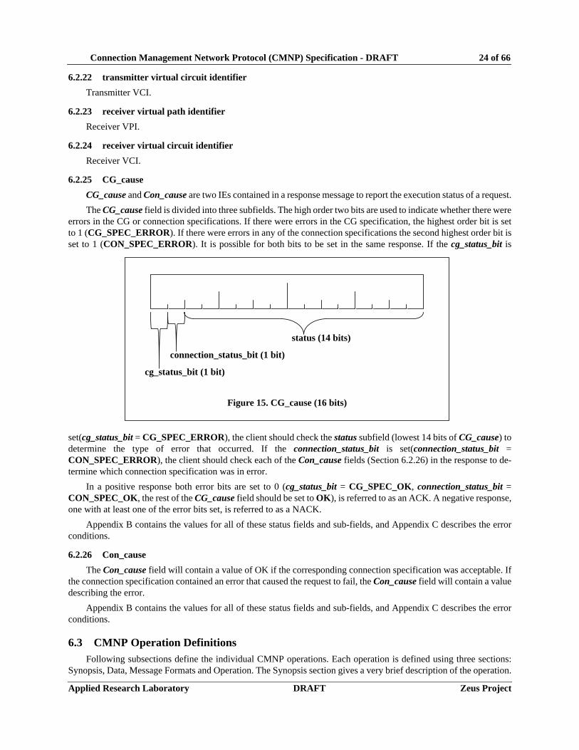


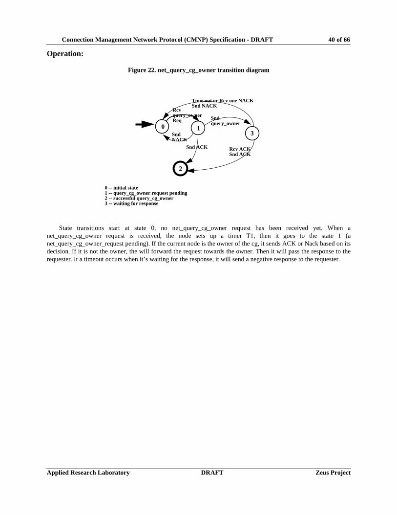


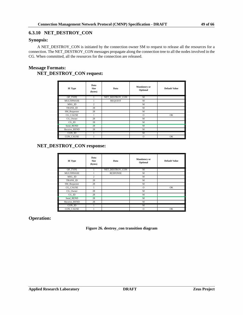


![[MS-TSRAP]: Telnet Server Remote Administration Protocol...telnet server: An implementation of the server side of Telnet Protocol [RFC854]. telnet session: An active telnet connection](https://static.documents.pub/doc/80x56/60b2d507b3d5e976d8381236/ms-tsrap-telnet-server-remote-administration-protocol-telnet-server-an-implementation.jpg)
![Network redundancy interoperability specification...ACMP AVDECC connection management protocol as described in [AVDECC, Clause 8]. ADP AVDECC discovery protocol as described in [AVDECC,](https://static.documents.pub/doc/80x56/5feef8d0970cd37b1c6b3825/network-redundancy-interoperability-specification-acmp-avdecc-connection-management.jpg)


![[MS-MICE]: Miracast over Infrastructure Connection ...MS-MICE].pdf · The Miracast over Infrastructure Connection Establishment Protocol specifies a connection negotiation sequence](https://static.documents.pub/doc/80x56/5e7c827e8767e15b77761f89/ms-mice-miracast-over-infrastructure-connection-ms-micepdf-the-miracast.jpg)


