Revision and Errata List, December 1, 2003 Hollows Structural Sections Connections Manual The following editorial corrections have been made in the First Printing, 1997. To facilitate the incorporation of these corrections, this booklet has been constructed using copies of the revis ed pages, with corrections noted. The user may find it convenient in some cases to hand-write a correction; in others, a cut-and-paste approach may be more efficient.
Revision and Errata List, December 1, 2003Hollows Structural Sections Connections Manual
The following editorial corrections have been made in theFirst Printing, 1997. To facilitate the incorporation of thesecorrections, this booklet has been constructed using copiesof the revised pages, with corrections noted. The user mayfind it convenient in some cases to hand-write a correction;in others, a cut-and-paste approach may be more efficient.
tubular members. However, certain types of tubular connections, such as unbacked T-,Y-, and K-connections, require special welder certifications because the lack of accessto the back of the joint, the position of the connection, and the access to the connectionrequire special skill to produce a sound connection.
Fig. 2-15. Prequalified joint details for complete joint penetration groove welds in tubular (HSS) T-, Y-, and
K-Connections—concave improved profile for heavysections or fatigue.
Bearing strength at bolt holes, and beam end distance
Use Equation 4-3 or 4-4 as applicable with Local web yielding
4-22
where
Web crippling
For
4-23a
For
4-23b
where
TEE CONNECTIONSSince load tables are not provided for tee connections, this type of connection will beused as an example of design using the limit state equations.
Notes:1. Values shown assume 70 ksi electrodes. For 60 ksi electrodes, multiply tabular values by 0.857,
or enter table with 1.17 times the required strength R u. For 80 ksi electrodes, multiply tabular valuesby 1.14, or enter table with 0.875 times the required strength R u.
2. Tabulated values are valid for stiffeners with minimum thickness of
but not less than 2 w for stiffeners with F y = 36 ksi nor 1.5 w for stiffeners with F y = 50 ksi. In the above, tw isthe thickness of the unstiffened supported beam web and w is the nominal weld size.
3. Tabulated values may be limited by shear yielding of or bearing on the stiffener; refer to LRFD SpecificationSections F2.2 and J8, respectively.
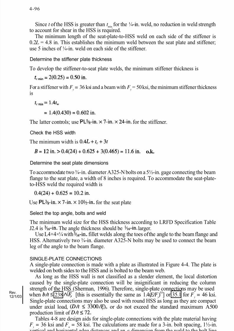
Since t of the HSS is greater than t min for the ¼-in. weld, no reduction in weld strengthto account for shear in the HSS is required.
The minimum length of the seat-plate-to-HSS weld on each side of the stiffener is0.2 L = 4.8 in. This establishes the minimum weld between the seat plate and stiffener;use 5 inches of ¼-in. weld on each side of the stiffener.
Determine the stiffener plate thickness
To develop the stiffener-to-seat plate welds, the minimum stiffener thickness is
For a stiffener with F y = 36 ksi and a beam with F y = 50 ksi, the minimum stiffener thicknessis
The latter controls; use for the stiffener.
Check the HSS width
The minimum width is
o.k.
Determine the seat plate dimensions
To accommodate two ¾-in. diameter A325-N bolts on a 5½-in. gage connecting the beamflange to the seat plate, a width of 8 inches is required. To accommodate the seat-plate-to-HSS weld the required width is
Use for the seat plate
Select the top angle, bolts and weld
The minimum weld size for the HSS thickness according to LRFD Specification TableJ2.4 is The angle thickness should be larger.
Use L4×4×¼ with fillet welds along the toes of the angle to the beam flange and HSS. Alternatively two ¾-in. diameter A325-N bolts may be used to connect the beamleg of the angle to the beam flange.
SINGLE-PLATE CONNECTIONSA single-plate connection is made with a plate as illustrated in Figure 4-4. The plate iswelded on both sides to the HSS and is bolted to the beam web.
As long as the HSS wall is not classified as a slender element, the local distortioncaused by the single-plate connection will be insignificant in reducing the column
strength of the HSS (Sherman, 1996). Therefore, single-plate connections may be used when [this is essentially the same as 1.4( E/F y)0.5] or 35.1 for F y = 46 ksi.
Single-plate connections may also be used with round HSS as long as they are compactunder axial load, or do not exceed the standard maximum A500 production limit of
Tables 4-8 are design aids for single-plate connections with the plate material havingF y = 36 ksi and F u = 58 ksi. The calculations are made for a 3-in. bolt spacing, 1½-in.vertical and horizontal edge distances and an a dimension from the weld to the bolt line
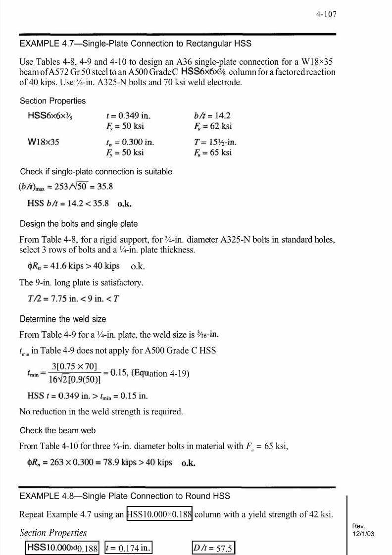
EXAMPLE 4.7—Single-Plate Connection to Rectangular HSS
Use Tables 4-8, 4-9 and 4-10 to design an A36 single-plate connection for a W18×35 beam of A572 Gr 50 steel to an A500 Grade C column for a factored reactionof 40 kips. Use ¾-in. A325-N bolts and 70 ksi weld electrode.
Section Properties
Check if single-plate connection is suitable
o.k.
Design the bolts and single plate
From Table 4-8, for a rigid support, for ¾-in. diameter A325-N bolts in standard holes,select 3 rows of bolts and a ¼-in. plate thickness.
o.k.
The 9-in. long plate is satisfactory.
Determine the weld size
From Table 4-9 for a ¼-in. plate, the weld size is
t min in Table 4-9 does not apply for A500 Grade C HSS
(Equation 4-19)
No reduction in the weld strength is required.
Check the beam web
From Table 4-10 for three ¾-in. diameter bolts in material with F u = 65 ksi,
o.k.
EXAMPLE 4.8—Single Plate Connection to Round HSS
Repeat Example 4.7 using an HSS10.000×0.188 column with a yield strength of 42 ksi.
No change from Example 4.7. Use three ¾-in. diameter A325-N bolts in standard holeswith a ¼-in. thick plate that is 9-in. long. The distance from the HSS to the bolt line is 3inches and the horizontal edge distance is 1½-in., making the plate width 4½-in.
Determine the weld size
From Table 4-9 for a ¼-in. plate, the weld size is and t min = 7.73 / F ySince
Reevaluate the strength based on the shear of the HSS wall effective weld size (Equation4-19).
Determine the weld eccentricity based on the bolt eccentricity from Equation 4-2.
Since the value in the absolute braces is negative, the eccentricity is between the HSSand the bolt line.
Using e x = 2 in., a = e x /l = 2/9 = 0.22, in LRFD Manual Table 8-38 and k = 0 for anout-of-plane eccentricity by interpolation, C = 2.58
(Equation 4-17)
o.k.
Check the beam web
No change from Example 4.7. The beam web is satisfactory.
THROUGH-PLATE CONNECTIONSIn the through-plate connection shown in Figure 4- 1e, the front and rear faces of the HSSare slotted so that the plate can be passed completely through the HSS and welded to bothfaces. The plate acts as a reinforcement to the HSS walls and through-plate connectionsshould be used when the HSS wall is classified as a slender element with b/t >
or 37.3 for F y = 46 ksi ( is the same as 1.4( E/F y)0 . 5 ). However, a single
plate connection is more economical and should be used if the HSS is neither slender nor inadequate for the punching shear rupture limit state in AISC HSS Specification Sec-tion 9.3.3.
Through-plate connections have the same limit states as single-plate connections and Table 4-8 may be used to determine the size and number of bolts and the plate thickness.All values are to be compared to factored loads. The welds, however, are subject to directshear and may not have to be as large as those for single plate connections. For equilibrium
of the forces in Fig. 4-5, the shear in the welds on the front face is Ru(H + e w)/H, whichshould not exceed the resistance of the pair of welds, in Table 4-9. If the thicknessof the HSS is less than the minimum in Table 4-9, the weld strength must be reduced
proportionally. The eccentricity is (n — 1) for n bolts in standard holes and 2 n/3 for short-slotted holes. Conservatively, the welds on the rear face may be the same size.
When a connection is made on both sides of the HSS with an extended through-plate,the portion of the plate inside the HSS is subject to a uniform bending moment. For longconnections, this portion of the plate will buckle in a lateral-torsional mode prior toyielding, unless H is very small. Using a thicker plate to prevent lateral-torsional bucklingwould restrict the rotational flexibility of the connection. Therefore, it must be recognized that the plate may buckle and that the moment will be shared with the HSS wall in acomplex manner. However, if the HSS is satisfactory when checked for the criteria of asingle plate connection, the lateral-torsional buckling limit state is not a critical concerninvolving loss of strength.
EXAMPLE 4.9—Through-Plate Connection
Redesign the connection in Example 4.7 using an with the connection to one
of the 6-in. faces.
Section Properties
The width B and the wall slenderness b/t are referenced to the loaded face of the HSS.The b/t is tabulated as h/t in the section properties tables.
Place stiffeners above each wall as illustrated in Figure 5-1(b).
Strength Based on Bolting and Welding
The maximum acceptable bolt tension may be calculated from the equation on p. 11-10of AISC LRFD Manual (AISC, 1994):
Setting t req = the cap plate thickness t p and rearranging
The bolt design strength (including prying) could be increased by increasing the cap platethickness. The bolt design strength (including prying), as limited by the beam, could be
increased by reducing the bolt gage. A 3-in. gage is a minimum based on the web and corner radius for this section. A wide flange section with a thicker flange or with a 50 ksiyield strength will permit a larger increase in bolt tension.
The weld of the cap plate to the HSS can be checked by evaluating2.61 kips/in. which can be satisfied with a 3/16-in. fillet weld with
HSS wall strength
In order to demonstrate the calculation for a concentrated load delivered from theW-shape web, ignore the fact that buckling of the W18 web required the use of stiffenersand evaluate wall yielding without stiffeners. Wall yielding can be evaluated using the
AISC HSS Specification, with the bearing width, N, taken as twice the k of the W section,and "k" taken as the cap plate thickness.
(K1-2)
Since C u is greater than 52.3 kips, the cap plate thickness could be increased or stiffenersadded to the W-shape to increase N, thus increasing the HSS wall yielding strength.
Next check wall crippling considering the W18×40 without stiffeners. Using the AISCHSS Specification expression for wall crippling with N = 2.38 in. from above, cap platethickness t 1 = 0.50 in., t = 0.233 in. and B = 8 in.
Use a ¾-in. A36 base plate thickness.Combined axial and bending strength of the cap plate
The interaction of flexure and tension is limited by Equations H1-1a and H1-1b in theSpecifications (AISC, 1994)
(H1-1a)
(H1-1b)
The cap plate is required to take an axial force of:
Note that the beam depth is used because the cap plate thickness is as yet unknown. If desired, the moment can be recalculated after the cap plate thickness is known.
Try a ¾-in. thick A36 cap plate.
Therefore Eq. H1-1a applies.
In the interaction equation the ratio of equals the ratio of from the bolttension.
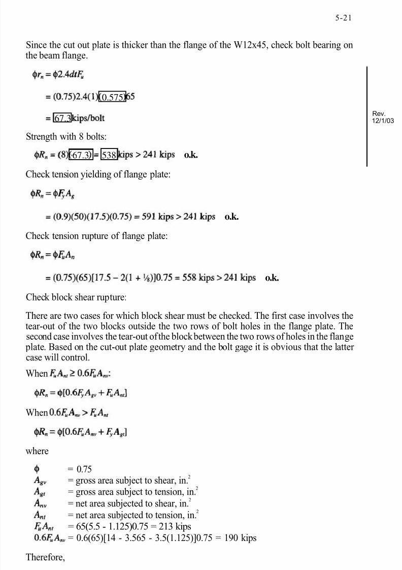
Since the cut out plate is thicker than the flange of the W12x45, check bolt bearing onthe beam flange.
Strength with 8 bolts:
o.k.
Check tension yielding of flange plate:
o.k.
Check tension rupture of flange plate:
o.k.
Check block shear rupture:There are two cases for which block shear must be checked. The first case involves thetear-out of the two blocks outside the two rows of bolt holes in the flange plate. Thesecond case involves the tear-out of the block between the two rows of holes in the flange
plate. Based on the cut-out plate geometry and the bolt gage it is obvious that the latter case will control.
HSS wall can resist the moment developed at the angle corner from prying. With theangles, the bolt gage would have to be increased by about 1 inch, which would place the
bolts ½-in. further from the flange tips. A b' value 0.5 inches larger than that used for theconnection plate may be reasonable.
Example 5.6—Directly Welded Connection of W Shape to HSS Column
Determine the flexural strength that can be transferred to an HSS column (A500Gr. B) by using the welded connection shown in Figure 5-9(a). The W sections are A36material.
1. A W14×43, or 2. A W16×36
Solution:
1. For the W14×43
Effective width limit
where
As noted earlier, this controls over the expression for local web yielding, webcrippling and punching shear.
Therefore, the design moment,
2. For the W16×36
Effective width limit
Check
Flange width is okay.
Per Equation 5.1
Face yielding limitPer Equation 5.3
For this section the face yielding limit controls and
Both values of are less than the plastic moment of the which equals(0.9)46(29.4) = 1,217 kip-in.
Example 5.7—Bolted HSS Face Connection
Determine the flexural strength that can be transferred to an column (A500Gr. B) by a W18×35 using one of the bolted connections illustrated in Figure 5-10.Allowing for the tee stem thicknesses and shim spacing, the center-to-center distance of the tees will be Consider use of nominal ¾-in. diameter blind bolts as shown inChapter 3 at a pitch of 3.5 inches. The ¾-in. diameter bolt requires a hole.Considering a possible maximum 3 t bend radius for the HSS wall the gage should be nomore than 4.75 inches to insure that the formed bolt head will bear on the flat portion of the wall. The largest gage will produce the greatest tensile design strength.
Face Yielding
Using Equation 5-4
With an spacing between the centers of the two bolt groups, there will be a designflexural strength of for the connection usingthe bolted end plate. This is less than achieved in Example 6 even though the beam used is deeper. This is due to a lower yield line strength.
electrode classification number, i.e., minimum specified strength, ksiangle of loading measured from the weld longitudinal axis, degrees0°effective area of weld throat, in. 2
effective weld size, in.
weld size, in.length of weld to HSS, in.l.0Hdepth of HSS section, in.
Strength Based on Gusset Plate Shear The procedure below is based on the minimum thickness that matches the shear yieldingstrength of the gusset plate with the strength of the weld metal.
The thickness of the gusset plate can be determined as follows:
weld size, in.specified minimum yield stress of the gusset plate, ksi
When the gusset plate thickness is less than the minimum, t 1 , the strength of the gusset plate in shear is equal to the strength of the weld multiplied by the ratio of the actualthickness to t 1.
Strength Based on Bolting to the Gusset PlateDesign Tensile Strength of the Gusset Plate:
Results: The connection strength in tension is governed by bolt shear.
t
Solution 2: Using the Tables
Using Table 6-3, select the weld sizes, weld length, gusset plate thickness, and number of bolts required to resist a factored tension load of 75 kips.
From Table 6-3, 50 percent Member Design Strength, o.k.
SLOTTED HSS/GUSSET PLATE CONNECTION (AXIAL COMPRESSION)For compression loads the limit states are:
1. Strength based on member shear.2. Strength of the weld connecting the gusset plate to the HSS.3. Strength based on gusset plate shear.4. Strength based on buckling of the gusset plate.
5. Strength based on bolting to the gusset plate.Strength Based on Member Shear
where
0.90.6F y Ae , kipsspecified minimum yield stress of the gusset plate, ksi
effective area of HSS wall, in.2
4Lwt length of weld to HSS, in.1.0 H
HSS wall thickness, in.depth of HSS section, in.
Strength of the Weld Connecting the Gusset Plate to the HSS
where
AMERICAN INSTITUTE OF STEEL CONSTRUCTION
0.75nominal weld strength, ksi0.6F EXX (1.0 + 0.5sin 1.5 )electrode classification number, i.e., minimum specified strength, ksiangle of loading measured from the weld longitudinal axis, degrees
Using Table 6-4, select the weld size, weld length, gusset plate thickness and number of bolts required to resist a factored compression load of 31.8 kips.
From Table 6-4, 25 percent Member Design Strength, o.k.
END PLATES (AXIAL TENSION)The limit states for an HSS with end plates are:
1. Yielding of the end plate.2. Tensile strength of the bolts.3. Strength of the weld connecting the end plate to the HSS.
End Plates on Round SectionsThe method provided below for the design of end plates for Round HSS is based onresearch by Igarashi et al (1985). This method permits prying action to occur at the limitstate. The connection is designed based on the limit state of yielding of the end plate.
Yielding of the End Plate
The thickness of the end plate is determined from the equation (Packer, 1992):
where
= the factored tension load on the HSS, kips= 0.90= specified minimum yield stress of the end plate, ksi
THROUGH PLATESThe limit states for an HSS with through plates are:
1. Shear strength of the HSS wall.2. Yielding of the HSS wall.3. Strength of weld connecting the through plate to the HSS.
4. Strength based on buckling of the through plate.5. Strength based on bolting to the through plate.
The design strength for each of the limit states is the same as that for face mounted gusset plates (see page 6-47) with the exception that the design strengths of limit states 1, 2 and 3 are doubled.
FACE MOUNTED TEEFace mounted tee connections, illustrated in Figure 6-16, are usually composed of theHSS and a structural tee welded to the wall of the HSS with the plate oriented along the
axis of the HSS. In lieu of the structural tee a fabricated tee section is often used.The design strength for a face mounted tee is determined from the limit states of theHSS and tee.
The limit states for the HSS and tee are:
1. Strength of the HSS side wall.2. Strength of the weld connecting the HSS to the tee flange.3. Yielding of the tee flange.4. Shear yielding of the tee flange.5. Strength of the weld connecting the tee flange to the tee stem.
6. Strength based on buckling of the tee stem.7. Strength based on bolting to the tee stem.
Strength of the HSS Side Wall(a) Local Yielding
where
= 1.0
= outside corner radius of the HSS, in., which if not known may be taken as 1.5 t = HSS wall thickness, in.= length of the tee flange, in.= specified minimum yield stress of the HSS, ksi
(b) Web Crippling for Compressive Load Only
where
= 0.75= HSS wall thickness, in.= width of the tee flange, in.= flat width of the side wall of the HSS, in.= modulus of elasticity, ksi= minimum specified yield stress of the HSS, ksi
Strength of the Weld Connecting the HSS to the Face Plate
where
0.75nominal weld strength, ksi
electrode classification number, i.e., minimum specified strength, ksieffective area of weld throat, in. 2
nominal outside corner radius, in.2t HSS wall thickness, in.width of the tee flange, in.
Yielding of the Tee Flange
where
0.9specified minimum yield stress of the tee flange, ksiwidth of the tee flange, in.tee flange thickness, in.width of the HSS wall face to which the tee flange is connected, in.
Shear Yielding of the Tee Flange
where
0.90specified minimum yield stress of the tee flange, ksiwidth of the tee stem, in.tee flange thickness, in.
Strength of the Weld Connecting the Tee Flange to the Tee Stem
where
0.75nominal weld strength, ksi
electrode classification number, i.e., minimum specified strength, ksiangle of loading measured from the weld longitudinal axis, degrees90°effective area of weld throat, in. 2
0.707(2W s)Wweld size (tee flange to tee stem), in.
Axial Compression Loading:HSS column base plates can be designed based on the cantilever projection of the base
plate from the walls of the HSS.
A design procedure identical to that contained in the AISC LRFD Manual can be used provided adjustments are made for the "m" and "n" distances for round HSS. DeWolf and Ricker (1990) point out that for round HSS the cantilever projection can bedetermined using a cantilever projection based on 0.8 times the outside diameter, and for rectangular or square HSS 0.95 times the outside dimension of the HSS. These designdimensions are shown in Fig. 7-2.
Axial Tensile LoadingFor base plates subjected to tensile loads base plate thicknesses can be determined usingcantilever beam theory in a manner identical to that used for the design of cap platessubjected to tensile concentrated loads. However, in cases where the anchor rods are
positioned as shown in Figure 7-3 an alternate procedure must be used.Unfortunately published solutions to determine base plate thickness or weld design
strength for the base plate-anchor rod condition shown in Figure 7-3 do not exist. Byexamining Figure 7-3 it is obvious that the weld at the flange tip is subjected to aconcentration of load because of the location of the anchor rod. The following design
procedure is suggested for this condition.
1. The effective width of the base plate, b e, should be taken as 2 L.2. The maximum effective width to be used is five inches.3. A maximum weld length of four inches can be used to transmit load between the
base plate and the column section.4. The base plate must be thick enough so as not to over strain the welds.
In equation format the design strength for a single anchor rod can be expressed as follows:Based on the plate effective width:
For the branch connection in Figure 9-4 at the support detail where there is only one branch member, use twice the perimeter of the branch member in determiningaccording to the definition given earlier.
At panel point 4
At panel point 10 with 5×5 branch members
The branch design strength equals
Therefore, HSS5×5 branch members will work throughout the entire truss.
Branch Member Selection—Interior
Determine thickness required for the third and fourth diagonals.
For
In tension,
From Table 9-1 and compressiveare okay by inspection for the remaining interior diagonals.
If it were necessary to reduce steel weight further, the use of a smaller size such as anHSS3½×3½ could be evaluated. However, labor savings due to repetition and uniformitymay offset the cost of additional steel weight.
Since all three exceed 17.3 kips, the connection of the HSS2.375×0.154 at the topchord is satisfactory throughout the truss.
The connection at the bottom chord with the vertical member present represents acombined K- and T-connection. With 5-in. diameter web members, the maximum gap
between web members (when e = 0.25 D) is
This permits the installation of the HSS2.375×0.154 vertical leaving a 0.95-in. gap asshown in Figure 9-7(a).
Consider the use of a thick by 4-in. wide plate to connect the vertical member atthe bottom chord as illustrated in Figure 9-7(b). This permits the use of the gapped connection where the 6.875-in. diameter web members are employed.
Use of the chord strength expression for transverse plates from the AISC HSSSpecification results in a relatively conservative value for the connection strength to thechord.
An alternative connection for the top chord could be a plate positioned longitudinally asillustrated in Fig. 9-7(b). Consider a plate thick and 6 inches long. Using AISC HSSSpecification Section 8.2 for this case
SPECIFICATION FOR THE DESIGN OF STEEL HOLLOW STRUCTURAL SECTIONS 17
chords and branches in T-, Y- and K-connections and less than or equal to 40for chords of Cross-connections
4) width ratio:5) gap: g greater than or equal to the sum of the branch wall thicknesses
2b. Branches with Axial Loads
For T-, Y-, and gapped K-connections, the design strength of the branch shall be determined from the limit states of chord wall plastification and punchingshear rupture. For Cross-connections, the design strength of the branch shall
be determined from the limit states of chord wall plastification, punching shear rupture and general collapse.
1. For the limit state of chord wall plastification,
(9.4-3)
where
For
For
= chord ovalization parameter = 1.7 for T- and Y-connections
for gapped K-connections= 2.4 for Cross-connections
2. For the limit state of punching shear rupture,
(9.4-4)
3. For the limit state of general collapse,
(9.4-5)
2c. Branches with Flexure
For T-, Y-, gapped K-, and Cross-connections, the design strength of the branchshall be determined from the limit states of chord wall plastification and
punching shear rupture.
1. For the limit state of chord wall plastification,
SPECIFICATION FOR THE DESIGN OF STEEL HOLLOW STRUCTURAL SECTIONS 19
3a. Limits of Applicability
The criteria herein are applicable only when the connection configuration iswithin the following limits:
1) joint eccentricity: where H is the chord depth and e is positive away from the branches
2) branch angle:3) wall stiffness: ratio of wall width to wall thickness less than or equal to 35
for chords and branches; also less than or equal to for branchesincompression
4) strength: F y less than or equal to 52 ksi for chord and branches5) chord aspect ratio: ratio of depth to width6) ductility:7) other limits apply for specific criteria
3b. Branches with Axial Loads in T-, Y- and Cross-connections
For T-, Y-, and Cross-connections, the design strength of the branch shall bedetermined from the limit states of chord wall plastification, punching shear rupture, sidewall strength, and uneven load distribution.
1. For the limit state of chord wall plastification,
(9.4-11)
This limit state need not be checked when nor when
2. For the limit state of punching shear rupture,
(9.4-12)
In the above equation, the effective outside punching parameter shall not exceed This limit state need not be checked when
nor when
3. For the limit state of sidewall strength, the design strength for branches intension shall be taken as the design strength for local sidewall yielding. For the limit state of sidewall strength, the design strength for branches incompression shall be taken as the lesser of the design strengths for localsidewall yielding and sidewall crippling. This limit state need not be checked
unless the chord member and branch member have the same widthFor the limit state of local yielding,
= 1.0 for a branch in tension= 0.8 for a branch in compression
20 SPECIFICATION FOR THE DESIGN OF STEEL HOLLOW STRUCTURAL SECTIONS
where
k = outside corner radius of the HSS, which is permitted to be taken as1.5t if unknown
N = bearing length of the load along the length of the HSS, H b = height of the branch
For the limit state of sidewall crippling, in T- and Y-connections,
(9.4-14)
For the limit state of sidewall crippling in Cross-connections,
(9.4-15)
4. For the limit state of uneven load distribution,
(9.4-16)
where
(9.4-17)
F yb = branch yield strengtht b = branch thickness
This limit state need not be checked when
3c. Branches with Axial Loads in Gapped K-connections
For gapped K-connections, the design strength of the branch shall bedetermined from the limit states of chord wall plastification, punching shear rupture, shear yielding, and uneven load distribution.
1. For the limit state of chord wall plastification,
(9.4-18)
where is the sum of the perimeters of the two branches divided by 8 timesthe chord width. This limit state need not be checked when