38
Consideration of Design Extension Conditions when Assessing Technology The EPR Technology Franck Lignini

Consideration of Design Extension Conditions when Assessing
Technology
The EPR Technology
Franck Lignini

Technology Assessment for New Nuclear Power Programmes – Vienna - 2015, September 2 2
Context NE Series NP-T-1-10 ‘Nuclear Reactor Technology
Assessment for Near Term Development’
Applicable to all phases of the NPP programme as defined in the “Milestones” document NG-G-3.1
Proposes a list of focus areas
“HIGH” weighing factors include
Safety
Proven technology
Compliance with regulation and licensing requirements
Key topics and key questions are proposed
Safety : safety margins, DiD, passive vs active safety systems,
probabilistics and deterministic safety evaluation
Technology maturity
As part of technology assessment, safety systems and engineered safety features must be carefully assessed especially
In case of innovative technology
Regarding “new“ IAEA design requirements introduced in SSR-2/1,
dealing in particular with ‘Design Extension Conditions’ and ‘Practical
Elimination’

Technology Assessment for New Nuclear Power Programmes – Vienna - 2015, September 2 3
Outline
“New” IAEA Design Requirements (SSR-2/1)
Considerations for Technology Assessment
Consideration of Design Extension Conditions in the EPR
Technology

Technology Assessment for New Nuclear Power Programmes – Vienna - 2015, September 2 4
Reminder on IAEA Design Requirements
SSR-2/1 published in 2012
Revision 1 under the publication process with integration of lessons
learned from the Fukushima Daiichi accident
“New” or more stringent requirements compared to NS-R-1
(2000)
A new TECDOC ‘Considerations on the Application of the IAEA Safety
Requirements for Design of Nuclear Power Plants’ will soon be published
(reviewed in June by members of the IAEA Nuclear Safety Standards Committee - NUSSC)
The following topics needed extensive discusion before consensus could
be reached
Use of the term ‘Design Basis’ for the plant
Association of Plant States with levels of DiD, in particular for DECs without core damage.
Consideration of the use of non permanent equipment for new plants
Concept of practical elimination
List of DECs without core damage given as examples in the TECDOC

Technology Assessment for New Nuclear Power Programmes – Vienna - 2015, September 2 5
SSR-2/1 Reqt 20 ‘Design Extension Conditions’
Design Extension Conditions
A set of events without significant fuel degradation (DEC A) or conditions with core melt (DEC B)
Engineering judgment, deterministic assessments and probabilistic assessments
Improve safety by enhancing the capability of the plant to withstand conditions generated by accidents that are more severe than Design Basis Accidents or that involve additional failures
Some DECs were already taken into account on existing plants (SBO, ATWS)
Considered in the design process of the plant
Additional safety features or extension of the capability of safety systems to prevent or to mitigate the consequences of a severe accident or to maintain the integrity of the containment
Obj : Reach controlled state - Containment function can be maintained
Radioactive releases must remain within acceptable limits
Possibility of plants states arising that could lead to an early radioactive release or a large
radioactive releases is practically eliminated
Effectiveness of provisions to ensure the functionality of the containment could be analyzed on the basis of the best estimate approach

Technology Assessment for New Nuclear Power Programmes – Vienna - 2015, September 2 6
SSR-2/1 Reqt 20 ‘Design Extension Conditions’
Design Extension Conditions
DEC ‘A’ DEC ‘B’

Technology Assessment for New Nuclear Power Programmes – Vienna - 2015, September 2 7
SSR-2/1 Reqt 20 ‘Design Extension Conditions’
Features for DEC
Features specifically designed for use in DEC or features capable of
preventing or mitigating DECs
Independent to the extent practicable of those used in more frequent accidents
Capable of performing in the environmental conditions pertaining to DECs, including severe accident conditions where appropriate
- For returning the plant to a safe state or for mitigating the consequences of an accident,
consideration could be given to full design capabilities of the plant and to temporary use of
additional systems
Reliability commensurate with the function that they are required to fulfill

Technology Assessment for New Nuclear Power Programmes – Vienna - 2015, September 2 8
SSR-2/1 Reqt 7 ‘Application of DiD’
The design of a nuclear power plant shall incorporate defence
in depth. The levels of defence in depth shall be independent
as far as is practicable
4.14 The levels of defence in depth shall be independent as far as
practicable to avoid the failure of one level reducing the effectiveness of
other levels. In particular, safety features for design extension conditions
(especially features for mitigating the consequences of accidents
involving the melting of fuel) shall as far as is practicable be independent
of safety systems
Demonstration of independence of the concerned provisions
implemented for the different levels of DiD should be provided
for each sequence of events

Technology Assessment for New Nuclear Power Programmes – Vienna - 2015, September 2 9
Outline
“New” IAEA Design Requirements (SSR-2/1)
Considerations for Technology Assessment
Consideration of Design Extension Conditions in the EPR
Technology

Technology Assessment for New Nuclear Power Programmes – Vienna - 2015, September 2 10
Performing Technology Assessment
Have Design Extension Conditions been
adequately considered in the design of the reactor ?
How was the list of DECs established ?
Was a systematic approach adopted, based on deterministic
considerations with probabilistic insights ?
How independent are engineered safety features for DECs from safety
systems used for more frequent accidents ?
For new technology, is the experience feedback sufficient to establish a
list of DECs ?
For example, it is important to understand
How the failure modes of passive systems are established
How they were validated and qualified – whether there are remaining uncertainties and potential cliff-edge effects
How the reliability of innovative equipment and passive systems is determined
Whether they can be tested

Technology Assessment for New Nuclear Power Programmes – Vienna - 2015, September 2 11
Performing Technology Assessment
In Annex III, NP-T-1.10 ‘Nuclear Reactor Technology
Assessment for Near Term Deployment suggests weighing
factors for “evaluation criteria” (MAUT or Kepner-Tregoe
process)
Reliability 30%
Function and performance 15%
Safety 30%
Operation and maintenance 15%
Materials 10%

Technology Assessment for New Nuclear Power Programmes – Vienna - 2015, September 2 12
Reliability of Passive Systems
IAEA TECDOC 1698 (2013) – Performance Assessment of
Passive Gaseous Provisions (PGAP)
… the reliability of passive safety systems is crucial and must be assessed before they are used extensively in future nuclear power plants. Several physical parameters affect the performance of a passive safety system, and their values at the time of operation are a priori unknown. The functions of many passive systems are based on thermohydraulic principles, which until recently were considered as not being subject to any kind of failure. Hence, large and consistent efforts are required to quantify the reliability of such systems.
Difficult to model accurately the characteristics of thermalhydraulic passive systems
Large scale uncertainties in simulation, particularly
Low flow natural circulation
Natural circulation flow instabilities
Critical heat flux under oscillary conditions
Condensation in presence of non condensable gases
…
Several physical parameters affect the performance of a passive safety system and their values at the time of operation are a priori unknown
Large and consistent efforts are required to quantify the reliability of passive systems

Technology Assessment for New Nuclear Power Programmes – Vienna - 2015, September 2 13
Reliability of Passive Systems
IAEA TECDOC 1752 (2014) - Progress in
Methodologies for the Assessment of Passive Safety
Systems Reliability in Advanced Reactors
The principal conclusion of the CRP is that there is a clear need to obtain more
data, especially related to thermal hydraulics
The technical challenges for advanced reactors also include … the potential
unavailability of important reliability and experimental data
Failure of passive components and structures now more important in advanced
reactor designs. The new and advanced Methodologies described in the report
for the assessment of passive safety system reliability are considered as
important tools and approaches to achieve improved safety for the future
advanced nuclear power plants and particular attention should be paid to the
status of development of the methodologies and the obtained results.
The general consensus was that a more practical approach would be very
helpful for the robust design and qualification of advanced nuclear reactors.
e.g. full scale mock-up

Technology Assessment for New Nuclear Power Programmes – Vienna - 2015, September 2 14
Outline
“New” IAEA Design Requirements (SSR-2/1)
Considerations for Technology Assessment
Consideration of Design Extension Conditions in the EPR
Technology

Technology Assessment for New Nuclear Power Programmes – Vienna - 2015, September 2 15
EPR Technology
Consideration of DEC A on EPR technology
Systematic approach : deterministic supplemented by probabilistic
Proven technology with very significant experience feedback (69 NPPs in
France and Germany) + 4 EPR under construction in Finland, France and
China (x2)
Credible events resulting from multiple failures
Combination of AOO + “frequent” DBA (> 10-2 – 10-3 /y) with a common cause failure (CCF) affecting the safety systems from the main line of defense necessary to reach controlled state
CCF affecting one or more safety classified system necessary to ensure the fundamental safety functions during normal operation
From the beginning of the design process in order to anticipate results of
probabilistic assessment
Verification that provisions not affected by the CCF are sufficient to
reach controlled state
no need for additional provisions but it might be necessary to increase the capability of the existing provisions, or
inclusion of diversified provisions

Technology Assessment for New Nuclear Power Programmes – Vienna - 2015, September 2 16
EPR Technology
DEC A considered for the EPR Technology
ATWS
DBC 2 + Mechanical blockage of rods
DBC 2 + failure of I&C platform of the protection system
LOOP + failure of emergency DGs
Loss of main heat sink in normal operation
Loss of the main cooling chain (component cooling system + Essential
service water) in normal operation
Loss of Main feedwater system + loss of auxiliary feedwater system
SB LOCA + failure of MHSI
SB LOCA + failure of LHSI
SB LOCA + loss of main cooling chain
CCF of fuel pool cooling system
CCF of HVAC in Electrical and I&C rooms in normal operation
As relevant, impact on both reactor and fuel building assessed, for
relevant plant operating conditions (power, shutdown states)

Technology Assessment for New Nuclear Power Programmes – Vienna - 2015, September 2 17
Need for DEC A Provisions - Illustration
CDF ≤ 10-5/y (int + ext)
CDF ≤ 10-6/y (int. events)
CDF ≤ 10-7/y (family of events)
CCF safety
system ~ 10-4
Safety Features for DEC
Existing provisions (if not affected by the sequence and if
no excessive design adaptation )
Additional provisions (if existing ones are not sufficient)
Normal operation
+
AOO
DBA (DBC3)
DBA (DBC4)
1
10-2/y
10-4/y
10-6/y
« Frequent » PIE
~ 10-2-10-3/y

Technology Assessment for New Nuclear Power Programmes – Vienna - 2015, September 2 18
Need for DEC A Provisions - Illustration
CDF ≤ 10-5/y (int + ext)
CDF ≤ 10-6/y (int. events)
CDF ≤ 10-7/y (family of events)
CCF safety
system ~ 10-4
Safety Features for DEC
Existing provisions (if not affected by the sequence and if
no excessive design adaptation )
Additional provisions (if existing ones are not sufficient)
Normal operation
+
AOO
DBA (DBC3)
DBA (DBC4)
1
10-2/y
10-4/y
10-6/y

Technology Assessment for New Nuclear Power Programmes – Vienna - 2015, September 2 19
Illustration – SB LOCA (not compensated by CVCS)
CDF ≤ 10-5/y (int + ext)
CDF ≤ 10-6/y (int. events)
CDF ≤ 10-7/y (family of events)
Normal operation
+
AOO
DBA (DBC3)
DBA (DBC4)
1
10-2/y
10-4/y
10-6/y
CCF MHSI
Accumulator
+ LHSI +
Secondary
cooldown
Existing provisions (not affected by the sequence)
with adaptation of their design
to cope with the sequence
SB LOCA
Technology Assessment for New Nuclear Power Programmes – Vienna - 2015, September 2 20
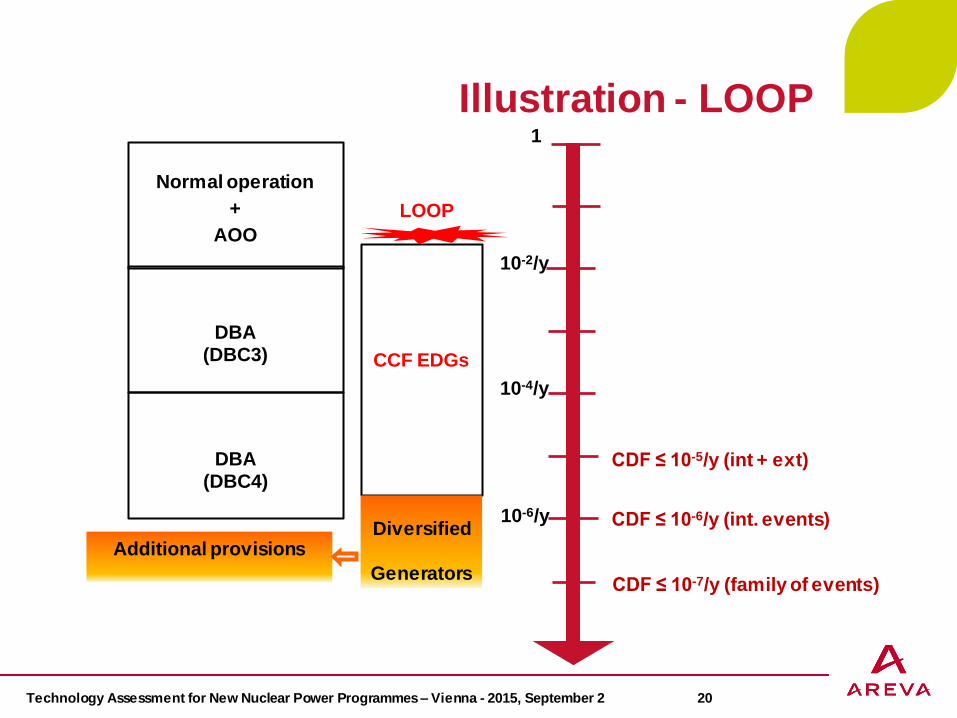
Illustration - LOOP
CDF ≤ 10-5/y (int + ext)
CDF ≤ 10-6/y (int. events)
CDF ≤ 10-7/y (family of events)
Normal operation
+
AOO
DBA (DBC3)
DBA (DBC4)
1
10-2/y
10-4/y
10-6/y
LOOP
CCF EDGs
Diversified
Generators
Additional provisions

Technology Assessment for New Nuclear Power Programmes – Vienna - 2015, September 2 21
Illustration - ATWS
CDF ≤ 10-5/y (int + ext)
CDF ≤ 10-6/y (int. events)
CDF ≤ 10-7/y (family of events)
Normal operation
+
AOO
DBA (DBC3)
DBA (DBC4)
1
10-2/y
10-4/y
10-6/y
DBC 2
CCF on RPS
Diversified
I&C
platform Additional provisions (DAS)
Existing provisions (SAS) (not affected by the sequence) +
additional signals

Technology Assessment for New Nuclear Power Programmes – Vienna - 2015, September 2 22
EPR Technology
DEC B on EPR technology
Deterministic approach aiming at covering all severe accident
situations not practically eliminated, that may jeopardize containment
integrity, i.e.
RPV failure at low pressure
Hydrogen production and combustion inside the containment
Pressure and temperature increase inside the containment
Interaction of molten corium with structures and management of the risk of basemat failure
3 types of postulated scenarii (independently of DEC A provisions)
“Fast” scenario with low primary pressure and high residual heat (e.g. similar to largest break LOCA event ) design of corium spreading area and design of CHRS
“Slow” scenario with low primary pressure and low residual heat (e.g. similar to small break LOCA event) design of corium spreading area and hydrogen recombiners
Scenario with high primary pressure and high residual heat (e.g. to similar total loss of SG feedwater event with failure of “feed & bleed”) design of PZR SA depressurization valves and hydrogen recombiners

Technology Assessment for New Nuclear Power Programmes – Vienna - 2015, September 2 23
Severe Accident Approach
Severe accident
Event beyond the DBA & DEC-A, leading to core damage/melt (loss of the 1st barrier) and possibly to RPV failure (loss of the 2nd barrier)
Mitigation approach aims at ensuring containment integrity (3rd barrier)
Practical elimination of energetic phenomena that may lead to an
early containment failure
High Pressure core melt sequences
Steam explosion
Hydrogen detonation
Commitments to ensure the confinement integrity for any other
sequences following a core melting, including those leading to the
RPV failure at low pressure
Stabilization of molten corium
Containment heat removal
Limitation of radioactive releases
Protective measures limited in area and time
No long term off-site contamination

Technology Assessment for New Nuclear Power Programmes – Vienna - 2015, September 2 24
Typical Sequence of events
Core uncovering, heat-up
In-vessel core meltdown
Cladding oxidation, with H2 production, transport, release and
combustion
Corium relocation in RPV bottom end
RPV bottom end failure cannot be excluded for high
power core (typically > 1000 MWth)
Reactor vessel wall attack / melt-through
If vessel failure at high pressure, core debris and coolant ejection
If reactor pit flooded as on the picture on the left : Interaction
corium/water, with possible steam explosion
Ex-vessel corium spreading
Interaction corium-concrete
Effective corium cooling leading to solidification
Containment heat up and over-pressurization with failure risk
Fission product release if confinement leaks

Technology Assessment for New Nuclear Power Programmes – Vienna - 2015, September 2 25
Pressurizer
safety
valves
Dedicated severe
accident
depressurization valves
(2 x 2 valves)
Practical Elimination of High-pressure core melt
Should RPV fail at high pressure, core debris and coolant
ejection may lead to Direct Containment Heating
A primary depressurization system prevents
high-pressure core melt sequences above 20 bar
Dedicated depressurization valves supplement
the 3 PZR safety valves and provide a
safe/reliable RCS depressurization
Redundancy and Diversification
high probability of successful operation
Practical Elimination of
High Pressure Core Melt
RCS : Reactor Coolant System RPV : Reactor Pressure Vessel PZR : Pressurizer

Technology Assessment for New Nuclear Power Programmes – Vienna - 2015, September 2 26
Practical Elimination of Steam Explosion
Steam Explosion (SE) is a
potentially destructive reaction
between the molten corium and
water
In-vessel SE
no risk of containment failure
(reaction confined within RPV)
Ex-vessel SE
Design provisions ensure dry reactor
pit and corium spreading area prior to
corium flooding Spreading Compartment
Basemat Cooling Melt PlugMelt Discharge Channel Protective Layer
-7.80m
IRWST
Sacrificial Material
Protective Layer
Sacrificial Material
discha

Technology Assessment for New Nuclear Power Programmes – Vienna - 2015, September 2 27
Oxidation of the Zr fuel cladding results in hydrogen production
Total oxidation of the Zr fuel cladding => 1684 kg H2 (concentration > 20%)
Global detonation is avoided as long as the average global H2
concentration within containment is < 10 % H2 (vol)
Large volume of containment (80 000m3) with ”open” compartments
No automatic early containment spray to avoid steam condensation
Practical Elimination of H2 Detonation

Technology Assessment for New Nuclear Power Programmes – Vienna - 2015, September 2 28
Practical Elimination of H2 Detonation
Prevention of fast deflagration or
of detonation ensured by Passive
Autocatalytic Recombiners
(PARs)
Maximum global containment pressure in the most limiting scenarios with H2 deflagration : 4,1 to 6,3 bar abs (containment integrity up to 6,5 bar abs)

Technology Assessment for New Nuclear Power Programmes – Vienna - 2015, September 2 29
Analysis of H2 Combustion

Technology Assessment for New Nuclear Power Programmes – Vienna - 2015, September 2 30
Core Melt Retention
Strategy, should the reactor vessel
fail :
Prevent corium-basemat interaction to avoid significant releases and durable contamination of sub-soil and underground waters.
Accumulate corium and temporarily retain it in the reactor pit after RPV failure
Delayed melting of a metal gate located at the bottom of the reactor pit
Spread the corium on a large surface outside of the reactor pit
Flood and cool the spreading area by IRWST water
Reactor pit
IRWST
Spreading areaSacrificial concrete
All stages are fully passive and have been tested and qualified (retention, spreading, flooding, cooling)

Technology Assessment for New Nuclear Power Programmes – Vienna - 2015, September 2 31
Temporary Core Melt Retention in Reactor Pit
Spreading Compartment
Basemat Cooling Melt PlugMelt Discharge Channel Protective Layer
-7.80m
IRWST
Sacrificial Material
Protective Layer
Sacrificial Material
Distinct separation of functions
between reactor pit
(accumulation) and
spreading compartment (cooling)
The core catcher is protected from loads
during RPV failure (melt jets, impact of
lower head)
The core melt / debris released after RPV-failure is accumulated in the Reactor Pit, with the target to :
- facilitate spreading in one event
- lower corium temperature and viscosity (Sacrificial concrete)

Technology Assessment for New Nuclear Power Programmes – Vienna - 2015, September 2 32
Passive Melt cooling
-2 ,3 0m
Sp re a d in g Co mp a rtme n t
Ba se ma t Co o lin g
+3 ,3 5 m
+1 ,5 0m
+5 .1 5 m
+4 .5 0m
-7 .8 0m
-6 .1 5 m
-0.7 0m
-1 .7 0m
-3 .9 6 m
IRWST
-2 .6 0m
+1 .5 0m
+5 ,6 4 m
Formation of a saturated water pool in the spreading compartment with steam release into containment
Gravity-driven overflow of water from the IRWST
At equilibrium water level, cooling is established also for debris potentially remaining within transfer channel and lower pit

Technology Assessment for New Nuclear Power Programmes – Vienna - 2015, September 2 33
-2 ,3 0m
Sp re a d in g Co mp a rtme n t
Ba se ma t Co o lin g
+3 ,3 5 m
+1 ,5 0m
+5 .1 5 m
+4 .5 0m
-7 .8 0m
-6 .1 5 m
-0.7 0m
-1 .7 0m
-3 .9 6 m
IRWST
-2 .6 0m
+1 .5 0m
+5 ,6 4 m
1000
100 50
500
200
100
Core Catcher

Technology Assessment for New Nuclear Power Programmes – Vienna - 2015, September 2 34
Core Melt Stabilization Concept Long Term phase
Actuation of the CHRS after a grace period of 12 hours allows
limiting the containment pressure
Possible switch between passive and active core catcher
cooling (not required) :
Formation of a sub-cooled water pool above the melt avoids the need for
further containment spraying after some days (atmospheric pressure
reached)
Effective cooling process due to large surface-to-volume ratio
of the melt, without interaction between melt and structural
concrete
Stable state of the melt, reached within hours
Total solidification of corium, within days
FILTERED VENTING NOT REQUIRED
CHRS : Containment Heat Removal System

Technology Assessment for New Nuclear Power Programmes – Vienna - 2015, September 2 35
Melt Cooling and Containment Heat Removal Long Term phase (beyond 12 hours grace period)
spray nozzles
xx
x
x
FL flow limiter
CHRS
water level in case of waterinjection into spreading compartment
(2x)
passive
spreading compartment
melt flooding via cooling deviceand lateral gap
in-containment refuelingwater storage tank
flooding device
Containment spray system
Recirculation and coolant heat exchanger
Water injection into the core
catcher
Two fully redundant trains with specific diversified heat sink

Technology Assessment for New Nuclear Power Programmes – Vienna - 2015, September 2 36
Conclusions Before GEN III+
Postulated Initiating Events : Deterministic approach
Design the main line of defense
Conservative approach, Single failure criterion
Not sufficient to address probabilistic targets (COD < 10-5/y, LERF < 10-6/y)
GEN III+ plants : design envelope is extended
DEC A (multiple failures without core melt)
CCF on the main line of defense for frequent PIE
CCF of safety/support systems in normal operation
DEC B (severe accidents with core melt)
Considered in the design in a deterministic manner
Mitigating features independent from main line of defense as far as reasonably practicable
Practical elimination of sequences leading to large or early radiological releases
Beyond Design Basis

Technology Assessment for New Nuclear Power Programmes – Vienna - 2015, September 2 37
Conclusions
When performing technology assessment, special attention should
be given to consideration of Design Extension Conditions and to
Practical Elimination with a high level of confidence, of sequences
leading to large or early radiological releases
In particular, several recent IAEA publications emphasize the importance of proven technology and suggest that significant effort is still needed to demonstrate the reliability of thermalhydraulic passive safety systems claimed in the safety demonstration for Design Extension Conditions
The EPR Technology is based on proven technology and safety
systems and engineered safety features for DEC have been qualified
In particular, the choice of ex-vessel corium cooling in case of severe
accident contributes to the practical elimination of uncontrolled
interaction between molten corium and water in the reactor pit that
could generate steam explosion resulting in early containment failure

Thank you for your attention


