27
CONSTANT HANGERS, CONSTANT SUPPORTS PRODUCT GROUP 1
CONSTANT HANGERS, CONSTANT SUPPORTS
PRODUCT GROUP
1
1.0
CONSTANT HANGERSCONSTANT SUPPORTS
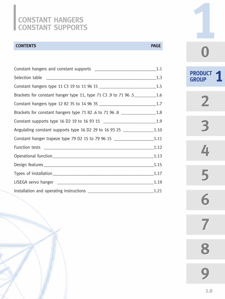
Constant hangers and constant supports ____________________________1.1
Selection table __________________________________________________1.3
Constant hangers type 11 C3 19 to 11 96 15 __________________________1.5
Brackets for constant hanger type 11, type 71 C3 .9 to 71 96 .5__________1.6
Constant hangers type 12 82 35 to 14 96 35 __________________________1.7
Brackets for constant hangers type 71 82 .6 to 71 96 .8 ________________1.8
Constant supports type 16 D2 19 to 16 93 15 ________________________1.9
Angulating constant supports type 16 D2 29 to 16 93 25 ______________1.10
Constant hanger trapeze type 79 D2 15 to 79 96 15 __________________1.11
Function tests __________________________________________________1.12
Operational function______________________________________________1.13
Design features __________________________________________________1.15
Types of installation______________________________________________1.17
LISEGA servo hanger ____________________________________________1.19
Installation and operating instructions ______________________________1.21
CONTENTS PAGE
0
2
3
4
5
6
7
8
9
0
2
3
4
5
6
7
8
9
PRODUCTGROUP
11
CONSTANT HANGERS, CONSTANT SUPPORTS, PRODUCT GROUP 1
1.1
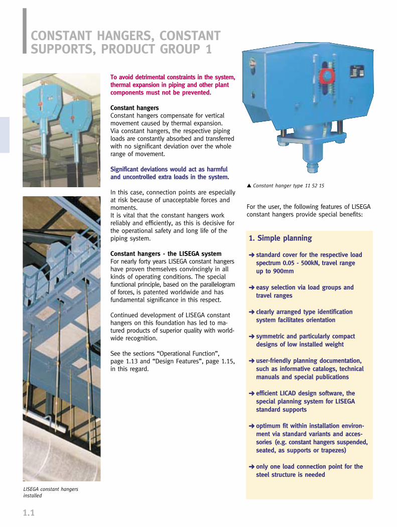
To avoid detrimental constraints in the system,thermal expansion in piping and other plantcomponents must not be prevented.
Constant hangersConstant hangers compensate for verticalmovement caused by thermal expansion. Via constant hangers, the respective pipingloads are constantly absorbed and transferredwith no significant deviation over the wholerange of movement.
Significant deviations would act as harmfuland uncontrolled extra loads in the system.
In this case, connection points are especiallyat risk because of unacceptable forces andmoments. It is vital that the constant hangers workreliably and efficiently, as this is decisive forthe operational safety and long life of thepiping system.
Constant hangers - the LISEGA systemFor nearly forty years LISEGA constant hangershave proven themselves convincingly in allkinds of operating conditions. The specialfunctional principle, based on the parallelogramof forces, is patented worldwide and hasfundamental significance in this respect.
Continued development of LISEGA constanthangers on this foundation has led to ma-tured products of superior quality with world-wide recognition.
See the sections “Operational Function”,page 1.13 and “Design Features”, page 1.15,in this regard.
▲ Constant hanger type 11 52 15
LISEGA constant hangers installed
For the user, the following features of LISEGAconstant hangers provide special benefits:
1. Simple planning
➜ standard cover for the respective load spectrum 0.05 - 500kN, travel range up to 900mm
➜ easy selection via load groups and travel ranges
➜ clearly arranged type identification system facilitates orientation
➜ symmetric and particularly compact designs of low installed weight
➜ user-friendly planning documentation, such as informative catalogs, technical manuals and special publications
➜ efficient LICAD design software, the special planning system for LISEGA standard supports
➜ optimum fit within installation environ-ment via standard variants and acces-sories (e.g. constant hangers suspended,seated, as supports or trapezes)
➜ only one load connection point for thesteel structure is needed
2. Easy installation
➜ compact, symmetric designs with only one suspension point and practical installation aids
➜ favorable weight performance ratios of the units reduce skeleton weight
➜ precision fit attachment devices by way of standardized elements
➜ ”intelligent“ travel stop enables easy conformity checks of set load and operating load
➜ extra wide load adjustment ranges (40 - 100% of nominal load) permit lateradjustment in the event of deviation in piping weights
3. Reliable operational safety
➜ due to the fundamental principle, abso-lute constancy over total set load range
➜ reduced frictional forces through a minimum of bearing points - the load is transferred vertically via the main spring(no friction through high lever bearing loads)
➜ operational travel runs straight through the symmetrical axis of the hanger, no load variations from radial deflection of the load distribution point (lever arm hanger)
➜ attachment point and load point always lie in the symmetrical axis (no moment of force exertion on the connection structures through radial deflection)
➜ lasting loadbearing performance through the use of specially treated prerelaxed springs
➜ lasting operating performance through corrosion protection and maintenance-free special steel bearings
4. Easy monitoring
➜ directly readable scales for travel position and operating load
➜ permanent marking for cold/hot positions and set load
➜ controlled subsequent load adjustment possible after installation
➜ simple reinstallation of blocking devicesfor inspection work
1.2
Construction series ‘64
Construction series ‘72
Construction series ‘76
Construction series ‘85
The 4 development stages ofLISEGA constant hangers
1
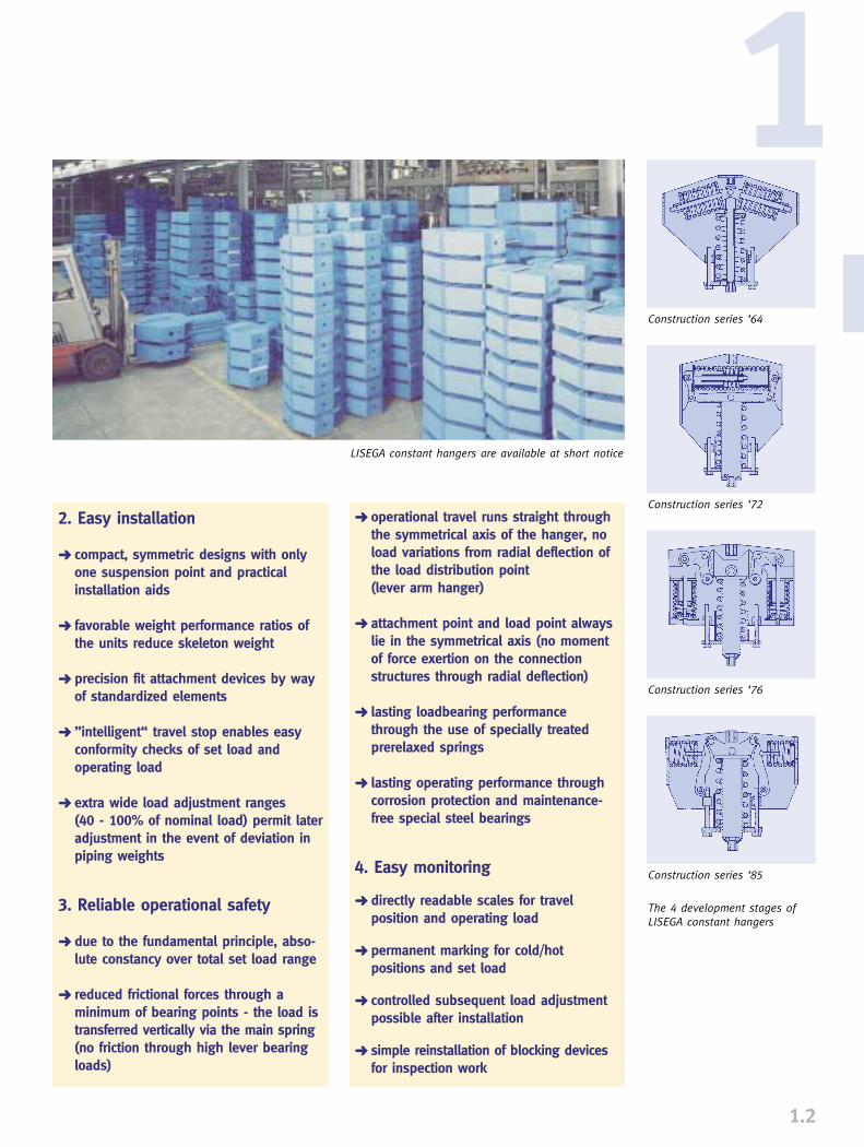
LISEGA constant hangers are available at short notice
750
700
650
600
550
500
450
400
350
300
250
200
150
100
50
0
0 0.625 1.25 2.5 5 10 15 20 30 40 50 60 70 80 90 100 120 140
SELECTION TABLE
1.3
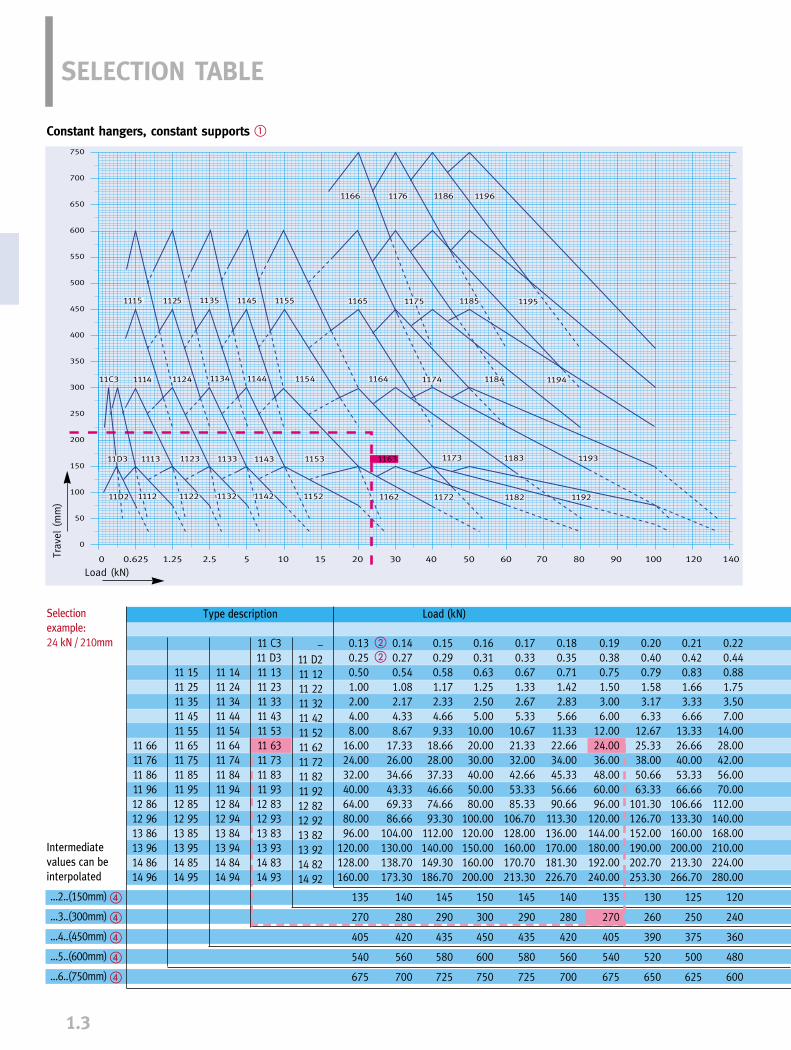
Constant hangers, constant supports �
Trav
el (
mm
)
Load (kN)
11 1511 2511 3511 4511 5511 6511 7511 8511 9512 8512 9513 8513 9514 8514 95
11 6611 7611 8611 9612 8612 9613 8613 9614 8614 96
11 1411 2411 3411 4411 5411 6411 7411 8411 9412 8412 9413 8413 9414 8414 94
–11 D211 1211 2211 3211 4211 5211 6211 7211 8211 9212 8212 9213 8213 9214 8214 92
0.130.250.501.002.004.008.00
16.0024.0032.0040.0064.0080.0096.00
120.00128.00160.00
135
270
405
540
675
0.140.270.541.082.174.338.67
17.3326.0034.6643.3369.3386.66
104.00130.00138.70173.30
140
280
420
560
700
0.150.290.581.172.334.669.33
18.6628.0037.3346.6674.6693.30
112.00140.00149.30186.70
145
290
435
580
725
0.160.310.631.252.505.00
10.0020.0030.0040.0050.0080.00
100.00120.00150.00160.00200.00
150
300
450
600
750
0.170.330.671.332.675.33
10.6721.3332.0042.6653.3385.33
106.70128.00160.00170.70213.30
145
290
435
580
725
0.180.350.711.422.835.66
11.3322.6634.0045.3356.6690.66
113.30136.00170.00181.30226.70
140
280
420
560
700
0.190.380.751.503.006.00
12.0024.0036.0048.0060.0096.00
120.00144.00180.00192.00240.00
135
270
405
540
675
0.200.400.791.583.176.33
12.6725.3338.0050.6663.33
101.30126.70152.00190.00202.70253.30
130
260
390
520
650
0.220.440.881.753.507.00
14.0028.0042.0056.0070.00
112.00140.00168.00210.00224.00280.00
120
240
360
480
600
Type description Load (kN)
�
�
�
�
�
�� 0.21
0.420.831.663.336.66
13.3326.6640.0053.3366.66
106.66133.30160.00200.00213.30266.70
125
250
375
500
625
11 C311 D311 1311 2311 3311 4311 5311 6311 7311 8311 9312 8312 9313 8313 9314 8314 93
Selection
example:
24 kN / 210mm
Intermediate
values can be
interpolated
...2..(150mm)
...3..(300mm)
...4..(450mm)
...5..(600mm)
...6..(750mm)
1.4
750
700
650
600
550
500
450
400
350
300
250
200
150
100
50
0
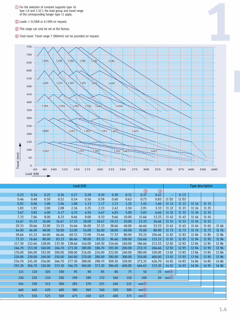
60 80 100 125 150 175 200 225 250 275 300 325 350 375 400 500 600
1Tr
avel
(m
m)
Load (kN)
� For the selection of constant supports type 16 (see 1.9 and 1.10 ), the load group and travel range of the corresponding hanger type 11 apply.
� Loads � 0.25kN or 0.13kN on request.
� This range can only be set at the factory.
� Total travel. Travel range 7 (900mm) can be provided on request.
11 1511 2511 3511 4511 5511 6511 7511 8511 9512 8512 9513 8513 9514 8514 95
11 6611 7611 8611 9612 8612 9613 8613 9614 8614 96
11 1411 2411 3411 4411 5411 6411 7411 8411 9412 8412 9413 8413 9414 8414 94
11 C311 D311 1311 2311 3311 4311 5311 6311 7311 8311 9312 8312 9313 8313 9314 8314 93
–11 D211 1211 2211 3211 4211 5211 6211 7211 8211 9212 8212 9213 8213 9214 8214 92
mm�
mm�
0.230.460.921.833.677.33
14.6729.3344.0058.6673.33
117.30146.70176.00220.00234.70293.30
115
230
345
460
575
0.240.480.961.923.837.66
15.3330.6646.0061.3376.66
122.66153.30184.00230.00245.30306.70
110
220
330
440
550
0.250.501.002.004.008.00
16.0032.0048.0064.0080.00
128.00160.00192.00240.00256.00320.00
105
210
315
420
525
0.260.521.042.084.178.33
16.6733.3350.0066.6683.33
133.30166.70200.00250.00266.70333.30
100
200
300
400
500
0.270.541.082.164.338.66
17.3334.6652.0069.3386.66
138.66173.30208.00260.00277.30346.70
95
190
285
380
475
0.280.561.132.254.509.00
18.0036.0054.0072.0090.00
144.00180.00216.00270.00288.00360.00
90
180
270
360
450
0.290.581.172.334.679.33
18.6737.3356.0074.6693.33
149.30186.70224.00280.00298.70373.30
85
170
255
340
425
0.300.601.212.424.839.66
19.3338.6658.0077.3396.66
154.66193.30232.00290.00309.30386.60
80
160
240
320
400
0.310.631.252.505.00
10.0020.0040.0060.0080.00
100.00160.00200.00240.00300.00320.00400.00
75
150
225
300
375
0.420.831.663.336.66
13.3326.6653.3380.00
106.66133.33213.33266.66320.00400.00426.70533.30
25
50
Load (kN)
0.370.731.452.915.83
11.6623.3346.6670.0093.33
116.66186.66233.33280.00350.00373.35466.65
50
100
mm�
mm�
mm�
� �
Type description
CONSTANT HANGER TYPE 11
1.5
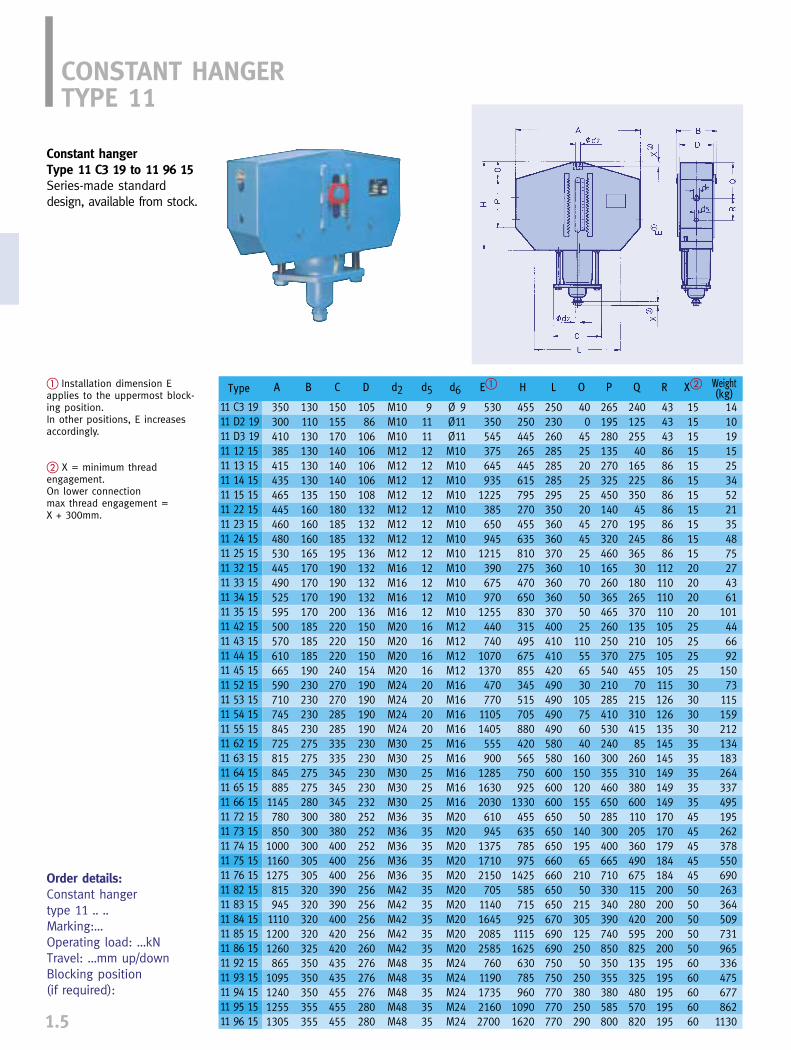
Constant hangerType 11 C3 19 to 11 96 15Series-made standarddesign, available from stock.
� Installation dimension Eapplies to the uppermost block-ing position.In other positions, E increases accordingly.
� X = minimum thread engagement.On lower connection max thread engagement = X + 300mm.
Order details:Constant hangertype 11 .. ..Marking:…Operating load: …kNTravel: …mm up/downBlocking position (if required):
A
350300410385415435465445460480530445490525595500570610665590710745845725815845885
1145780850
100011601275815945
111012001260865
1095124012551305
Type
11 C3 1911 D2 1911 D3 1911 12 1511 13 1511 14 1511 15 1511 22 1511 23 1511 24 1511 25 1511 32 1511 33 1511 34 1511 35 1511 42 1511 43 1511 44 1511 45 1511 52 1511 53 1511 54 1511 55 1511 62 1511 63 1511 64 1511 65 1511 66 1511 72 1511 73 1511 74 1511 75 1511 76 1511 82 1511 83 1511 84 1511 85 1511 86 1511 92 1511 93 1511 94 1511 95 1511 96 15
B
130110130130130130135160160160165170170170170185185185190230230230230275275275275280300300300305305320320320320325350350350355355
C
150155170140140140150180185185195190190190200220220220240270270285285335335345345345380380400400400390390400420420435435455455455
D
10586
106106106106108132132132136132132132136150150150154190190190190230230230230232252252252256256256256256256260276276276280280
d2
M10M10M10M12M12M12M12M12M12M12M12M16M16M16M16M20M20M20M20M24M24M24M24M30M30M30M30M30M36M36M36M36M36M42M42M42M42M42M48M48M48M48M48
d5
9111112121212121212121212121216161616202020202525252525353535353535353535353535353535
d6
Ø 9Ø11Ø11M10M10M10M10M10M10M10M10M10M10M10M10M12M12M12M12M16M16M16M16M16M16M16M16M16M20M20M20M20M20M20M20M20M20M20M24M24M24M24M24
Weight(kg)
1410191525345221354875274361
101446692
15073
115159212134183264337495195262378550690263364509731965336475677862
1130
E�
530350545375645935
1225385650945
1215390675970
1255440740
10701370470770
11051405555900
128516302030610945
137517102150705
1140164520852585760
1190173521602700
X�
15151515151515151515152020202025252525303030303535353535454545454550505050506060606060
H
455250445265445615795270455635810275470650830315495675855345515705880420565750925
1330455635785975
1425585715925
11151625630785960
10901620
L
250230260285285285295350360360370360360360370400410410420490490490490580580600600600650650650660660650650670690690750750770770770
O
400
4525202525204545251070505025
110556530
105756040
16015012015550
14019565
21050
21530512525050
250380250290
P
265195280135270325450140270320460165260365465260250370540210285410530240300355460650285300400665710330340390740850350355380585800
Q
24012525540
16522535045
19524536530
18026537013521027545570
21531041585
260310380600110205360490675115280420595825135325480570820
R
4343438686868686868686
112110110110105105105105115126126135145145149149149170170179184184200200200200200195195195195195
� The 5th digit of the type des-cription indicates the design:6 for brackets bolted on,
standard specification.7 for loose brackets,
standard specification.8 for brackets bolted on,
nuclear specification.9 for loose brackets,
nuclear specification.
� E in the uppermost blockingposition. In other positions, Edecreases accordingly.
� Constant hangers can be seated directly on the structureand welded in place. When doingthis, care must be taken to provideaccess to the adjusting screws andlock nut. If this access cannot be provided,type 71 brackets should be used.
Order details:Constant hanger type 11 .. .. with bracket type 71 .. .. Marking:Operating load: …kN,Travel: …mm up/downBlocking position (if required):
BRACKETS FOR CONSTANT HANGER TYPE 11
1.6
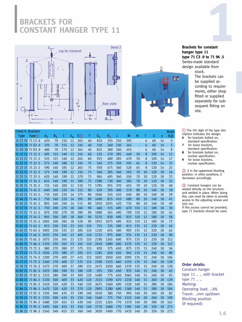
Brackets for constanthanger type 11type 71 C3 .9 to 71 96 .5Series-made standard design available from
stock.The brackets can be supplied ac-cording to require-ments, either shopfitted or supplied separately for sub-sequent fitting on site.
1Lug for transport
Base plate
Detail Z
Const h. Brackets WeightType Type� A1 B1 C d4 E� F G1 K1 L M N T U y (kg)
11 C3 19 71 C3 .9 420 70 150 12 265 40 810 355 250 395 - 6 60 14 511 D2 19 71 D2 .9 370 70 155 12 145 40 510 260 230 345 - 6 60 14 511 D3 19 71 D3 .9 480 70 170 12 265 40 825 380 260 455 - 6 60 14 811 12 15 71 12 .5 495 115 140 12 145 60 535 270 285 440 50 8 100 14 1211 13 15 71 13 .5 525 115 140 12 265 60 925 480 285 470 50 8 100 14 1711 22 15 71 22 .5 575 140 180 12 145 75 545 275 350 505 65 8 120 14 1511 23 15 71 23 .5 590 140 185 12 265 75 930 475 360 520 65 8 120 14 2111 32 15 71 32 .5 575 140 190 12 150 75 560 285 360 505 70 10 120 18 1611 33 15 71 33 .5 620 140 190 12 270 75 965 495 360 550 70 10 120 18 2311 34 15 71 34 .5 655 140 190 12 390 75 1380 730 360 585 70 10 120 18 3211 35 15 71 35 .5 725 140 200 12 510 75 1785 955 370 655 70 10 120 18 4011 42 15 71 42 .5 640 160 220 14 155 80 620 305 400 570 80 10 140 18 1811 43 15 71 43 .5 710 160 220 14 275 80 1040 545 410 640 80 10 140 18 2911 44 15 71 44 .5 750 160 220 14 395 80 1490 815 410 680 80 10 140 18 4111 45 15 71 45 .5 805 160 240 14 515 80 1910 1055 420 735 80 10 140 18 4911 52 15 71 52 .5 750 200 270 18 160 90 660 315 490 670 110 12 180 18 3011 53 15 71 53 .5 870 200 270 18 280 90 1080 565 490 790 110 12 180 18 4211 54 15 71 54 .5 905 200 285 18 400 90 1535 830 490 825 110 12 180 18 5811 55 15 71 55 .5 1005 200 285 18 520 90 1955 1075 490 925 110 12 180 18 7211 62 15 71 62 .5 915 250 335 23 165 110 755 335 580 815 135 12 220 18 4511 63 15 71 63 .5 1005 250 335 23 285 110 1220 655 580 905 135 12 220 18 6211 64 15 71 64 .5 1035 250 345 23 405 110 1725 975 600 935 135 12 220 18 9011 65 15 71 65 .5 1075 250 345 23 525 110 2190 1265 600 975 135 12 220 18 11211 66 15 71 66 .5 1335 250 345 23 345 110 2410 1080 600 1235 135 12 220 18 11211 72 15 71 72 .5 980 270 380 27 175 115 830 375 650 875 135 15 240 18 5611 73 15 71 73 .5 1050 270 380 27 295 115 1285 650 650 945 135 15 240 18 8011 74 15 71 74 .5 1200 270 400 27 415 115 1835 1050 650 1095 135 15 240 18 10611 75 15 71 75 .5 1360 270 400 27 535 115 2290 1315 660 1255 135 15 240 18 12811 76 15 71 76 .5 1475 270 400 27 280 115 2475 1050 660 1370 135 15 240 18 12811 82 15 71 82 .5 1025 280 390 33 180 120 935 350 650 935 140 15 240 18 6511 83 15 71 83 .5 1155 280 390 33 300 120 1490 775 650 1065 140 15 240 18 9111 84 15 71 84 .5 1320 300 400 33 420 120 2115 1190 670 1230 140 15 260 18 13911 85 15 71 85 .5 1410 320 420 33 540 120 2675 1560 690 1320 140 15 280 18 18411 86 15 71 86 .5 1470 320 420 33 270 120 2905 1280 690 1380 140 15 280 18 18411 92 15 71 92 .5 1105 300 435 33 190 140 1010 380 750 995 140 20 260 18 8211 93 15 71 93 .5 1335 300 435 33 310 140 1560 775 750 1225 140 20 260 18 10911 94 15 71 94 .5 1480 320 455 33 430 140 2225 1265 770 1370 140 20 280 18 16211 95 15 71 95 .5 1495 340 455 33 550 140 2770 1680 770 1385 140 20 320 18 27311 96 15 71 96 .5 1545 340 455 33 260 140 3020 1400 770 1435 140 20 320 18 273
CONSTANT HANGERTYPE 12-14
1.7
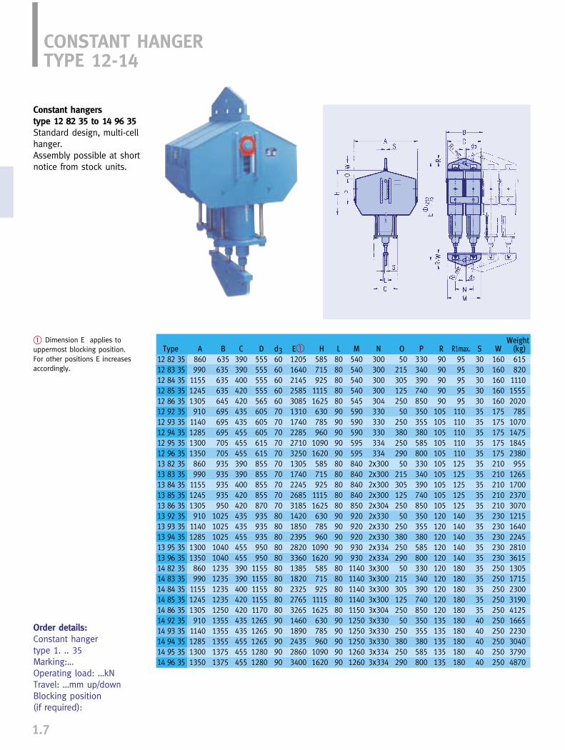
Constant hangers type 12 82 35 to 14 96 35Standard design, multi-cellhanger.Assembly possible at shortnotice from stock units.
� Dimension E applies touppermost blocking position. For other positions E increasesaccordingly.
Order details:Constant hangertype 1. .. 35Marking:…Operating load: …kNTravel: …mm up/downBlocking position (if required):
WeightH L M N O P R R1max. S W (kg)
585 80 540 300 50 330 90 95 30 160 615715 80 540 300 215 340 90 95 30 160 820925 80 540 300 305 390 90 95 30 160 1110
1115 80 540 300 125 740 90 95 30 160 15551625 80 545 304 250 850 90 95 30 160 2020630 90 590 330 50 350 105 110 35 175 785785 90 590 330 250 355 105 110 35 175 1070960 90 590 330 380 380 105 110 35 175 1475
1090 90 595 334 250 585 105 110 35 175 18451620 90 595 334 290 800 105 110 35 175 2380585 80 840 2x300 50 330 105 125 35 210 955715 80 840 2x300 215 340 105 125 35 210 1265925 80 840 2x300 305 390 105 125 35 210 1700
1115 80 840 2x300 125 740 105 125 35 210 23701625 80 850 2x304 250 850 105 125 35 210 3070630 90 920 2x330 50 350 120 140 35 230 1215785 90 920 2x330 250 355 120 140 35 230 1640960 90 920 2x330 380 380 120 140 35 230 2245
1090 90 930 2x334 250 585 120 140 35 230 28101620 90 930 2x334 290 800 120 140 35 230 3615585 80 1140 3x300 50 330 120 180 35 250 1305715 80 1140 3x300 215 340 120 180 35 250 1715925 80 1140 3x300 305 390 120 180 35 250 2300
1115 80 1140 3x300 125 740 120 180 35 250 31901625 80 1150 3x304 250 850 120 180 35 250 4125630 90 1250 3x330 50 350 135 180 40 250 1665785 90 1250 3x330 250 355 135 180 40 250 2230960 90 1250 3x330 380 380 135 180 40 250 3040
1090 90 1260 3x334 250 585 135 180 40 250 37901620 90 1260 3x334 290 800 135 180 40 250 4870
Type A B C D d3 E�
12 82 35 860 635 390 555 60 120512 83 35 990 635 390 555 60 164012 84 35 1155 635 400 555 60 214512 85 35 1245 635 420 555 60 258512 86 35 1305 645 420 565 60 308512 92 35 910 695 435 605 70 131012 93 35 1140 695 435 605 70 174012 94 35 1285 695 455 605 70 228512 95 35 1300 705 455 615 70 271012 96 35 1350 705 455 615 70 325013 82 35 860 935 390 855 70 130513 83 35 990 935 390 855 70 174013 84 35 1155 935 400 855 70 224513 85 35 1245 935 420 855 70 268513 86 35 1305 950 420 870 70 318513 92 35 910 1025 435 935 80 142013 93 35 1140 1025 435 935 80 185013 94 35 1285 1025 455 935 80 239513 95 35 1300 1040 455 950 80 282013 96 35 1350 1040 455 950 80 336014 82 35 860 1235 390 1155 80 138514 83 35 990 1235 390 1155 80 182014 84 35 1155 1235 400 1155 80 232514 85 35 1245 1235 420 1155 80 276514 86 35 1305 1250 420 1170 80 326514 92 35 910 1355 435 1265 90 146014 93 35 1140 1355 435 1265 90 189014 94 35 1285 1355 455 1265 90 243514 95 35 1300 1375 455 1280 90 286014 96 35 1350 1375 455 1280 90 3400
BRACKETS FORCONSTANT HANGER TYPE 12-14
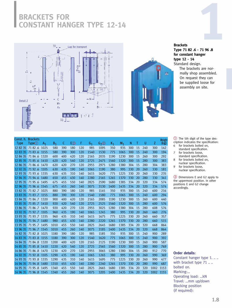
Brackets Type 71 82 .6 - 71 96 .8for constant hanger type 12 - 14Standard design.
The brackets are nor-mally shop assembled. On request they can be supplied loose forassembly on site.
� The 5th digit of the type des-cription indicates the specification:6 for brackets bolted on,
standard specification.7 for brackets loose,
standard specification.8 for brackets bolted on,
nuclear specification.9 for brackets loose,
nuclear specification.
� Dimensions E and G2 apply tothe uppermost position. In otherpositions E and G2 change accordingly.
Order details:Constant hanger type 1. .. ..with bracket type 71 .. ..bolted on.Marking:…Operating load: …kNTravel: …mm up/downBlocking position (if required):
1
1.8
Lug for transport
Detail Z
WeightG2� K1 M1 N T U Z (kg)
1095 350 935 300 15 240 300 1421530 775 1065 300 15 240 300 1942035 1190 1230 300 15 260 300 2922475 1560 1320 300 15 280 300 3832975 1280 1380 304 15 280 304 3831190 380 995 330 20 260 330 1811620 775 1225 330 20 260 330 2352165 1265 1370 330 20 280 330 3412590 1680 1385 334 20 320 334 5743130 1400 1435 334 20 320 334 5741145 350 935 300 15 240 600 2161580 775 1065 300 15 240 600 2942085 1190 1230 300 15 260 600 4402525 1560 1320 300 15 280 600 5763025 1280 1380 304 15 280 608 5761245 380 995 330 20 260 660 2761675 775 1225 330 20 260 660 3572220 1265 1370 330 20 280 660 5152645 1680 1385 334 20 320 668 8643185 1400 1435 334 20 320 668 8641185 350 935 300 15 240 900 2891620 775 1065 300 15 240 900 3922125 1190 1230 300 15 260 900 5872565 1560 1320 300 15 280 900 7693065 1280 1380 304 15 280 912 7701265 380 995 330 20 260 990 3691695 775 1225 330 20 260 990 4772240 1265 1370 330 20 280 990 6872665 1680 1385 334 20 320 1002 11533205 1400 1435 334 20 320 1002 1155
Const. h. BracketsType Type� A1 B1 C E� F G1
12 82 35 71 82 .6 1025 580 390 180 120 98512 83 35 71 83 .6 1155 580 390 300 120 154012 84 35 71 84 .6 1320 600 400 420 120 216512 85 35 71 85 .6 1410 620 420 540 120 272512 86 35 71 86 .6 1470 620 420 270 120 295512 92 35 71 92 .6 1105 630 435 190 140 106512 93 35 71 93 .6 1335 630 435 310 140 161512 94 35 71 94 .6 1480 650 455 430 140 228012 95 35 71 95 .6 1495 675 455 550 140 282512 96 35 71 96 .6 1545 675 455 260 140 307513 82 35 71 82 .7 1025 880 390 180 120 98513 83 35 71 83 .7 1155 880 390 300 120 154013 84 35 71 84 .7 1320 900 400 420 120 216513 85 35 71 85 .7 1410 920 420 540 120 272513 86 35 71 86 .7 1470 920 420 270 120 295513 92 35 71 92 .7 1105 960 435 190 140 106513 93 35 71 93 .7 1335 960 435 310 140 161513 94 35 71 94 .7 1480 980 455 430 140 228013 95 35 71 95 .7 1495 1010 455 550 140 282513 96 35 71 96 .7 1545 1010 455 260 140 307514 82 35 71 82 .8 1025 1180 390 180 120 98514 83 35 71 83 .8 1155 1180 390 300 120 154014 84 35 71 84 .8 1320 1200 400 420 120 216514 85 35 71 85 .8 1410 1220 420 540 120 272514 86 35 71 86 .8 1470 1230 420 270 120 295514 92 35 71 92 .8 1105 1290 435 190 140 106514 93 35 71 93 .8 1335 1290 435 310 140 161514 94 35 71 94 .8 1480 1310 455 430 140 228014 95 35 71 95 .8 1495 1340 455 550 140 282514 96 35 71 96 .8 1545 1340 455 260 140 3075
CONSTANT SUPPORTTYPE 16
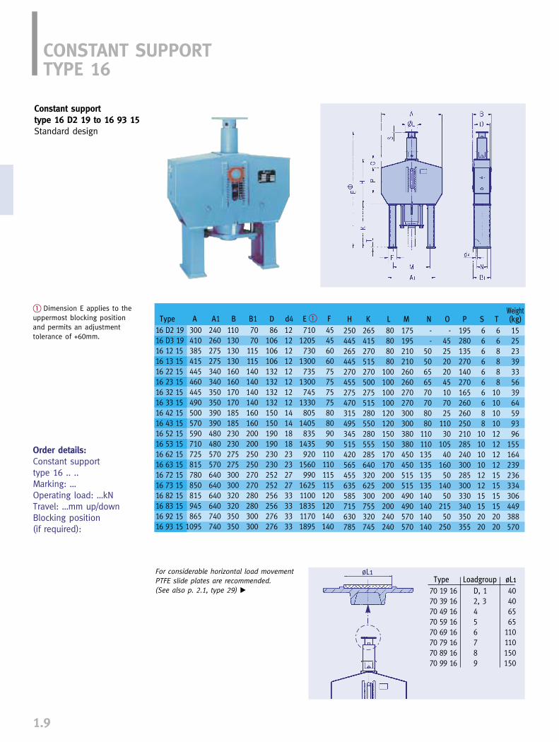
Constant supporttype 16 D2 19 to 16 93 15Standard design
� Dimension E applies to theuppermost blocking positionand permits an adjustment tolerance of +60mm.
Order details:Constant support type 16 .. ..Marking: …Operating load: …kNTravel: …mm up/downBlocking position (if required):
1.9
For considerable horizontal load movement PTFE slide plates are recommended.(See also p. 2.1, type 29) �
øL1Type Loadgroup øL1
70 19 16 D, 1 4070 39 16 2, 3 4070 49 16 4 6570 59 16 5 6570 69 16 6 11070 79 16 7 11070 89 16 8 15070 99 16 9 150
WeightH K L M N O P S T (kg)
250 265 80 175 - - 195 6 6 15445 415 80 195 - 45 280 6 6 25265 270 80 210 50 25 135 6 8 23445 515 80 210 50 20 270 6 8 39270 270 100 260 65 20 140 6 8 33455 500 100 260 65 45 270 6 8 56275 275 100 270 70 10 165 6 10 39470 515 100 270 70 70 260 6 10 64315 280 120 300 80 25 260 8 10 59495 550 120 300 80 110 250 8 10 93345 280 150 380 110 30 210 10 12 96515 555 150 380 110 105 285 10 12 155420 285 170 450 135 40 240 10 12 164565 640 170 450 135 160 300 10 12 239455 320 200 515 135 50 285 12 15 236635 625 200 515 135 140 300 12 15 334585 300 200 490 140 50 330 15 15 306715 755 200 490 140 215 340 15 15 449630 320 240 570 140 50 350 20 20 388785 745 240 570 140 250 355 20 20 570
Type A A1 B B1 D d4 E � F
16 D2 19 300 240 110 70 86 12 710 4516 D3 19 410 260 130 70 106 12 1205 4516 12 15 385 275 130 115 106 12 730 6016 13 15 415 275 130 115 106 12 1300 6016 22 15 445 340 160 140 132 12 735 7516 23 15 460 340 160 140 132 12 1300 7516 32 15 445 350 170 140 132 12 745 7516 33 15 490 350 170 140 132 12 1330 7516 42 15 500 390 185 160 150 14 805 8016 43 15 570 390 185 160 150 14 1405 8016 52 15 590 480 230 200 190 18 835 9016 53 15 710 480 230 200 190 18 1435 9016 62 15 725 570 275 250 230 23 920 11016 63 15 815 570 275 250 230 23 1560 11016 72 15 780 640 300 270 252 27 990 11516 73 15 850 640 300 270 252 27 1625 11516 82 15 815 640 320 280 256 33 1100 12016 83 15 945 640 320 280 256 33 1835 12016 92 15 865 740 350 300 276 33 1170 14016 93 15 1095 740 350 300 276 33 1895 140
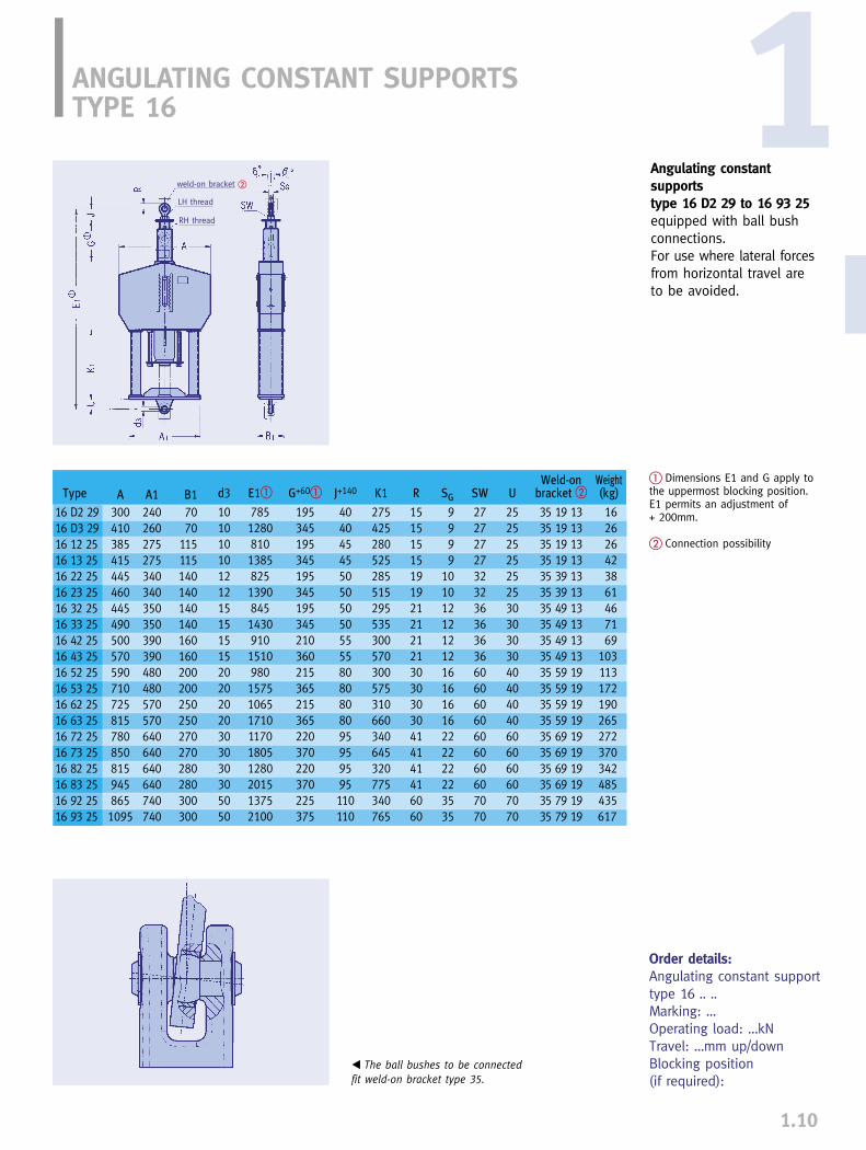
ANGULATING CONSTANT SUPPORTSTYPE 16
Angulating constant supportstype 16 D2 29 to 16 93 25equipped with ball bushconnections.For use where lateral forcesfrom horizontal travel areto be avoided.
1.10
� Dimensions E1 and G apply tothe uppermost blocking position.E1 permits an adjustment of + 200mm.
� Connection possibility
Order details:Angulating constant support type 16 .. ..Marking: …Operating load: …kNTravel: …mm up/downBlocking position (if required):
� The ball bushes to be connectedfit weld-on bracket type 35.
weld-on bracket �
LH thread
RH thread
Weld-on Weightd3 E1� G+60� J+140 K1 R SG SW U bracket � (kg)
10 785 195 40 275 15 9 27 25 35 19 13 1610 1280 345 40 425 15 9 27 25 35 19 13 2610 810 195 45 280 15 9 27 25 35 19 13 2610 1385 345 45 525 15 9 27 25 35 19 13 4212 825 195 50 285 19 10 32 25 35 39 13 3812 1390 345 50 515 19 10 32 25 35 39 13 6115 845 195 50 295 21 12 36 30 35 49 13 4615 1430 345 50 535 21 12 36 30 35 49 13 7115 910 210 55 300 21 12 36 30 35 49 13 6915 1510 360 55 570 21 12 36 30 35 49 13 10320 980 215 80 300 30 16 60 40 35 59 19 11320 1575 365 80 575 30 16 60 40 35 59 19 17220 1065 215 80 310 30 16 60 40 35 59 19 19020 1710 365 80 660 30 16 60 40 35 59 19 26530 1170 220 95 340 41 22 60 60 35 69 19 27230 1805 370 95 645 41 22 60 60 35 69 19 37030 1280 220 95 320 41 22 60 60 35 69 19 34230 2015 370 95 775 41 22 60 60 35 69 19 48550 1375 225 110 340 60 35 70 70 35 79 19 43550 2100 375 110 765 60 35 70 70 35 79 19 617
Type A A1 B116 D2 29 300 240 7016 D3 29 410 260 7016 12 25 385 275 11516 13 25 415 275 11516 22 25 445 340 14016 23 25 460 340 14016 32 25 445 350 14016 33 25 490 350 14016 42 25 500 390 16016 43 25 570 390 16016 52 25 590 480 20016 53 25 710 480 20016 62 25 725 570 25016 63 25 815 570 25016 72 25 780 640 27016 73 25 850 640 27016 82 25 815 640 28016 83 25 945 640 28016 92 25 865 740 30016 93 25 1095 740 300
1
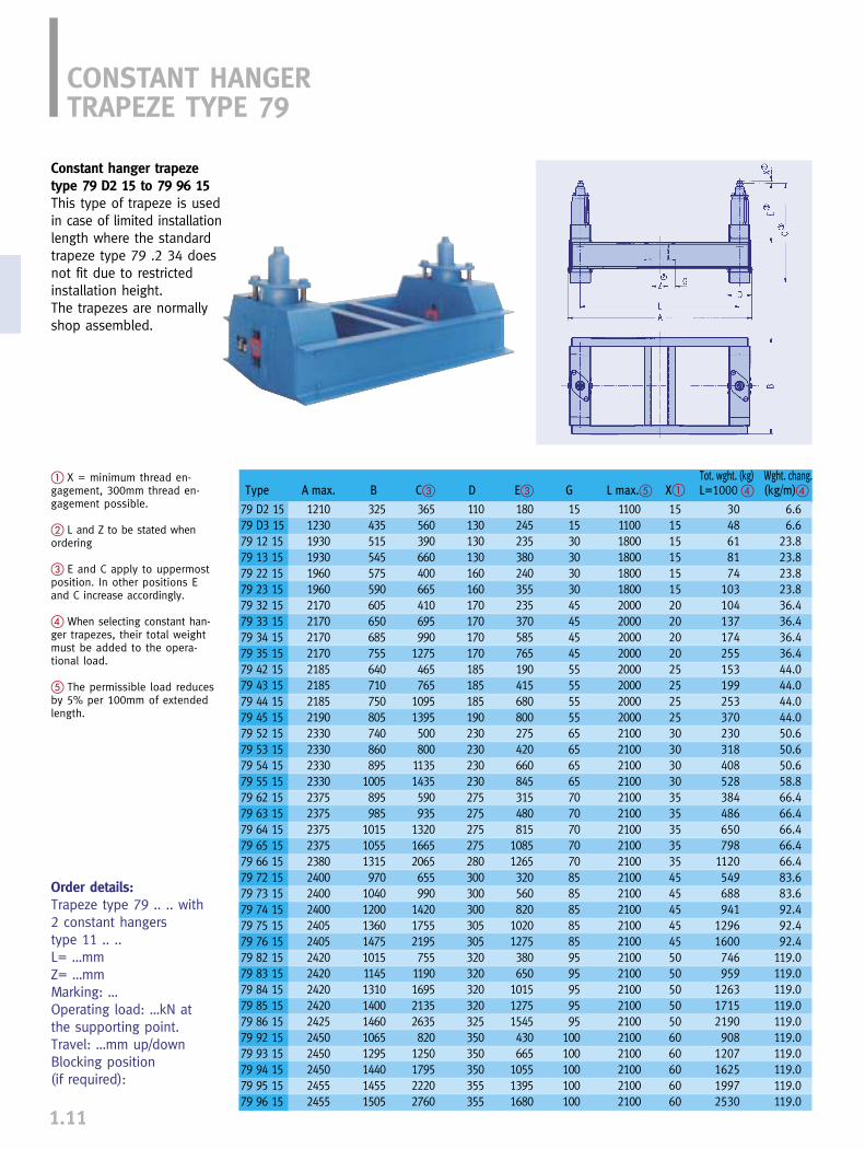
CONSTANT HANGER TRAPEZE TYPE 79
1.11
Constant hanger trapezetype 79 D2 15 to 79 96 15This type of trapeze is usedin case of limited installationlength where the standardtrapeze type 79 .2 34 doesnot fit due to restrictedinstallation height.The trapezes are normallyshop assembled.
� X = minimum thread en-gagement, 300mm thread en-gagement possible.
� L and Z to be stated whenordering
� E and C apply to uppermostposition. In other positions Eand C increase accordingly.
� When selecting constant han-ger trapezes, their total weightmust be added to the opera-tional load.
� The permissible load reducesby 5% per 100mm of extendedlength.
Order details:Trapeze type 79 .. .. with 2 constant hangerstype 11 .. ..L= …mmZ= …mmMarking: …Operating load: …kN at the supporting point.Travel: …mm up/downBlocking position (if required):
Type
79 D2 1579 D3 1579 12 1579 13 1579 22 1579 23 1579 32 1579 33 1579 34 1579 35 1579 42 1579 43 1579 44 1579 45 1579 52 1579 53 1579 54 1579 55 1579 62 1579 63 1579 64 1579 65 1579 66 1579 72 1579 73 1579 74 1579 75 1579 76 1579 82 1579 83 1579 84 1579 85 1579 86 1579 92 1579 93 1579 94 1579 95 1579 96 15
A max.
12101230193019301960196021702170217021702185218521852190233023302330233023752375237523752380240024002400240524052420242024202420242524502450245024552455
B
325435515545575590605650685755640710750805740860895
1005895985
101510551315970
10401200136014751015114513101400146010651295144014551505
C�
365560390660400665410695990
1275465765
10951395500800
11351435590935
132016652065655990
142017552195755
1190169521352635820
1250179522202760
D
110130130130160160170170170170185185185190230230230230275275275275280300300300305305320320320320325350350350355355
E�
180245235380240355235370585765190415680800275420660845315480815
10851265320560820
10201275380650
101512751545430665
105513951680
G
151530303030454545455555555565656565707070707085858585859595959595
100100100100100
L max.�
11001100180018001800180020002000200020002000200020002000210021002100210021002100210021002100210021002100210021002100210021002100210021002100210021002100
Tot. wght. (kg) Wght. chang.X� L=1000 � (kg/m)�
15 30 6.615 48 6.615 61 23.815 81 23.815 74 23.815 103 23.820 104 36.420 137 36.420 174 36.420 255 36.425 153 44.025 199 44.025 253 44.025 370 44.030 230 50.630 318 50.630 408 50.630 528 58.835 384 66.435 486 66.435 650 66.435 798 66.435 1120 66.445 549 83.645 688 83.645 941 92.445 1296 92.445 1600 92.450 746 119.050 959 119.050 1263 119.050 1715 119.050 2190 119.060 908 119.060 1207 119.060 1625 119.060 1997 119.060 2530 119.0
FUNCTION TESTS 1
1.12
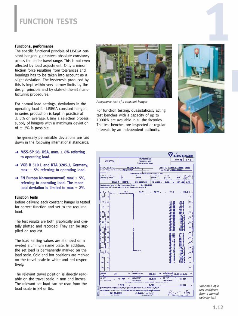
Specimen of atest certificatefrom a normaldelivery test
Functional performanceThe specific functional principle of LISEGA con-stant hangers guarantees absolute constancyacross the entire travel range. This is not evenaffected by load adjustment. Only a minorfriction force resulting from tolerances andbearings has to be taken into account as aslight deviation. The hysteresis produced bythis is kept within very narrow limits by thedesign principle and by state-of-the-art manu-facturing procedures.
For normal load settings, deviations in theoperating load for LISEGA constant hangersin series production is kept in practice at � 3% on average. Using a selection process,supply of hangers with a maximum deviationof � 2% is possible.
The generally permissible deviations are laiddown in the following international standards:
➜ MSS-SP 58, USA, max. � 6% referring to operating load.
➜ VGB R 510 L and KTA 3205.3, Germany, max. � 5% referring to operating load.
➜ EN Europa Normenentwurf, max � 5%, referring to operating load. The mean load deviation is limited to max � 2%.
Function testsBefore delivery, each constant hanger is testedfor correct function and set to the requiredload.
The test results are both graphically and digi-tally plotted and recorded. They can be sup-plied on request.
The load setting values are stamped on ariveted aluminum name plate. In addition,the set load is permanently marked on theload scale. Cold and hot positions are markedon the travel scale in white and red respec-tively.
The relevant travel position is directly read-able on the travel scale in mm and inches.The relevant set load can be read from theload scale in kN or lbs.
For function testing, quasistatically actingtest benches with a capacity of up to1000kN are available in all the factories. The test benches are inspected at regularintervals by an independent authority.
Acceptance test of a constant hanger
F
A
F1
B
E
C
D
F2
F
A
F1
B
D
C
E
F
A
B
C
D
E
F
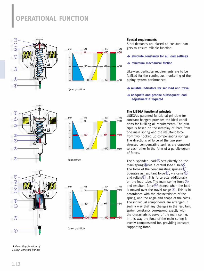
� Operating function of LISEGA constant hanger
2
Upper position
Midposition
Lower position
OPERATIONAL FUNCTION
1.13
Special requirementsStrict demands are placed on constant han-gers to ensure reliable function:
➜ absolute constancy for all load settings
➜ minimum mechanical friction
Likewise, particular requirements are to befulfilled for the continuous monitoring of thepiping system performance:
➜ reliable indicators for set load and travel
➜ adequate and precise subsequent load adjustment if required
The LISEGA functional principleLISEGA’s patented functional principle forconstant hangers provides the ideal condi-tions for fulfilling all requirements. The prin-ciple is based on the interplay of force fromone main spring and the resultant forcefrom two hooked up compensating springs.The directions of force of the two pre-stressed compensating springs are opposedto each other in the form of a parallelogramof forces.
The suspended load acts directly on themain spring via a central load tube . The force of the compensating springs operates as resultant force , via camsand rollers . This force acts additionallyon the load tube. The main spring forceand resultant force change when the loadis moved over the travel range . This is inaccordance with the characteristics of thespring, and the angle and shape of the cams.The individual components are arranged insuch a way that any changes in the resultantspring constancy correspond exactly withthe characteristic curve of the main spring.In this way the force of the main spring isevenly compensated for, providing constantsupporting force.
FF2
AB
F
1
s
D
E
F2
C
Large loadadjustment range
Small number of unitsizes (load groups,modular system)
Serial production(favorable
manufacturing costs)
Warehousing(short term availability)
LISEGA functional principle for
constant hangers
1.14
1Down towards the apex of the cams theresultant force diminishes in proportion tothe increase in the relatively low startingforce of the main spring.
At the apex of the cams the forces of thecompensating springs are cancelled out. The resultant is zero. At this point only themain spring carries the load. Beyond the apex,the direction of the proportionally increasingresultant force of the compensating springs isreversed. It now reduces the relatively strongmain spring force in the same way.
The sum of, or the difference between theforces F1 and F2 at each point in the travelrange = F.
➜ Only the LISEGA functional principle guarantees absolute constancy right from a theoretical basis.
➜ Only the LISEGA functional principle allows a particularly wide load adjustmentrange of 40 - 100% of the nominal load.
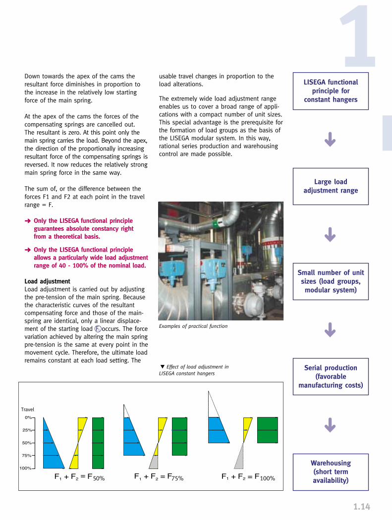
Load adjustmentLoad adjustment is carried out by adjustingthe pre-tension of the main spring. Becausethe characteristic curves of the resultantcompensating force and those of the main-spring are identical, only a linear displace-ment of the starting load occurs. The forcevariation achieved by altering the main springpre-tension is the same at every point in themovement cycle. Therefore, the ultimate loadremains constant at each load setting. The
usable travel changes in proportion to theload alterations.
The extremely wide load adjustment rangeenables us to cover a broad range of appli-cations with a compact number of unit sizes.This special advantage is the prerequisite forthe formation of load groups as the basis ofthe LISEGA modular system. In this way,rational series production and warehousingcontrol are made possible.
� Effect of load adjustment in LISEGA constant hangers
➜➜
➜➜
Examples of practical functionF1
Travel
1.15
Connection typesThe connection threads correspond to thestandardized diameter of the relevant LISEGAload group. At the upper connection thethread depth is limited. At the lower end, thenut is used as a turnbuckle for adjusting rodlength.
The shape of the hanger housing allows directseating on existing connection structureswithout extra accessories. In addition, specialbrackets can be attached using the standardtapped holes provided. Constant hangersabove load group 9 (heavy duty) have yokeplates for bolted connections instead ofconnection threads.
Performance rangeConstant hangers and supports are manufac-tured in load groups C - 9 as serialized single-cell units. They can also be coupled togetherfor load groups 8 or 9 as multi-cell hangerswith heavier loads. In this way a standardized range of 0.1 kNto 500 kN can be covered. Constant hangersare manufactured in 6 standard travel ranges:150/ 300/ 450/ 600/ 750/900mm - constantsupports up to 300mm.
Standards and calculationsComponent design and layout fully complyas regards load capacity, dynamic functionand lifespan with the relevant national andinternational standards and codes. This ap-plies equally to the materials used, weldingtechnology and other processes. Relevantdetails can be found in the TechnicalSpecifications (page 0.9).
SpringsThe springs are decisive for the flawless functioning of constant hangers – the longterm operational safety of these componentsdepends on them. DIN standards form thebasis of the LISEGA coil spring specifications.Details can be found in the TechnicalSpecifications in section 0.
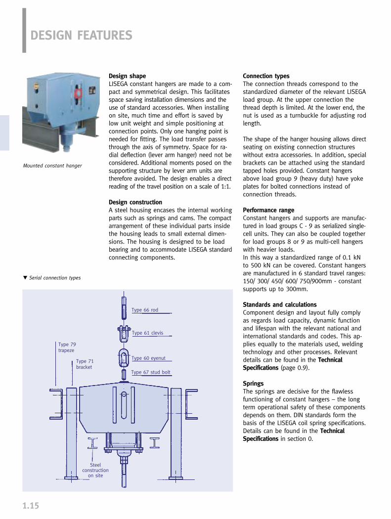
Mounted constant hanger
DESIGN FEATURES
Design shapeLISEGA constant hangers are made to a com-pact and symmetrical design. This facilitatesspace saving installation dimensions and theuse of standard accessories. When installingon site, much time and effort is saved bylow unit weight and simple positioning atconnection points. Only one hanging point isneeded for fitting. The load transfer passesthrough the axis of symmetry. Space for ra-dial deflection (lever arm hanger) need not beconsidered. Additional moments posed on thesupporting structure by lever arm units aretherefore avoided. The design enables a directreading of the travel position on a scale of 1:1.
Design constructionA steel housing encases the internal workingparts such as springs and cams. The compactarrangement of these individual parts insidethe housing leads to small external dimen-sions. The housing is designed to be loadbearing and to accommodate LISEGA standardconnecting components.
Type 79trapeze
Type 71bracket
Steel construction
on site
Type 66 rod
Type 61 clevis
Type 60 eyenut
Type 67 stud bolt
� Serial connection types
1.16
1
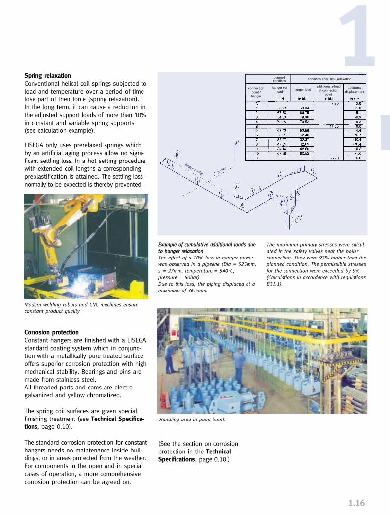
EExxaammppllee ooff ccuummuullaattiivvee aaddddiittiioonnaall llooaaddss dduueettoo hhaannggeerr rreellaaxxaattiioonnThe effect of a 10% loss in hanger powerwas observed in a pipeline (Dia = 525mm,s = 27mm, temperature = 540°C, pressure = 50bar).Due to this loss, the piping displaced at amaximum of 36.4mm.
The maximum primary stresses were calcul-ated in the safety valves near the boilerconnection. They were 93% higher than theplanned condition. The permissible stressesfor the connection were exceeded by 9%.(Calculations in accordance with regulationsB31.1).
Spring relaxationConventional helical coil springs subjected toload and temperature over a period of timelose part of their force (spring relaxation). In the long term, it can cause a reduction inthe adjusted support loads of more than 10%in constant and variable spring supports(see calculation example).
LISEGA only uses prerelaxed springs whichby an artificial aging process allow no signi-ficant settling loss. In a hot setting procedurewith extended coil lengths a correspondingpreplastification is attained. The settling lossnormally to be expected is thereby prevented.
Corrosion protectionConstant hangers are finished with a LISEGAstandard coating system which in conjunc-tion with a metallically pure treated surfaceoffers superior corrosion protection with highmechanical stability. Bearings and pins aremade from stainless steel. All threaded parts and cams are electro-galvanized and yellow chromatized.
The spring coil surfaces are given specialfinishing treatment (see Technical Specifica-tions, page 0.10).
The standard corrosion protection for constanthangers needs no maintenance inside buil-dings, or in areas protected from the weather.For components in the open and in specialcases of operation, a more comprehensivecorrosion protection can be agreed on.
Modern welding robots and CNC machines ensureconstant product quality
Handling area in paint booth
(See the section on corrosion protection in the TechnicalSpecifications, page 0.10.)
plannedcondition
connectionpoint / hanger
hanger setload
hanger load additional displacement
additional z-loadat connection
point
condition after 10% relaxation
boiler outlet boiler
1.17
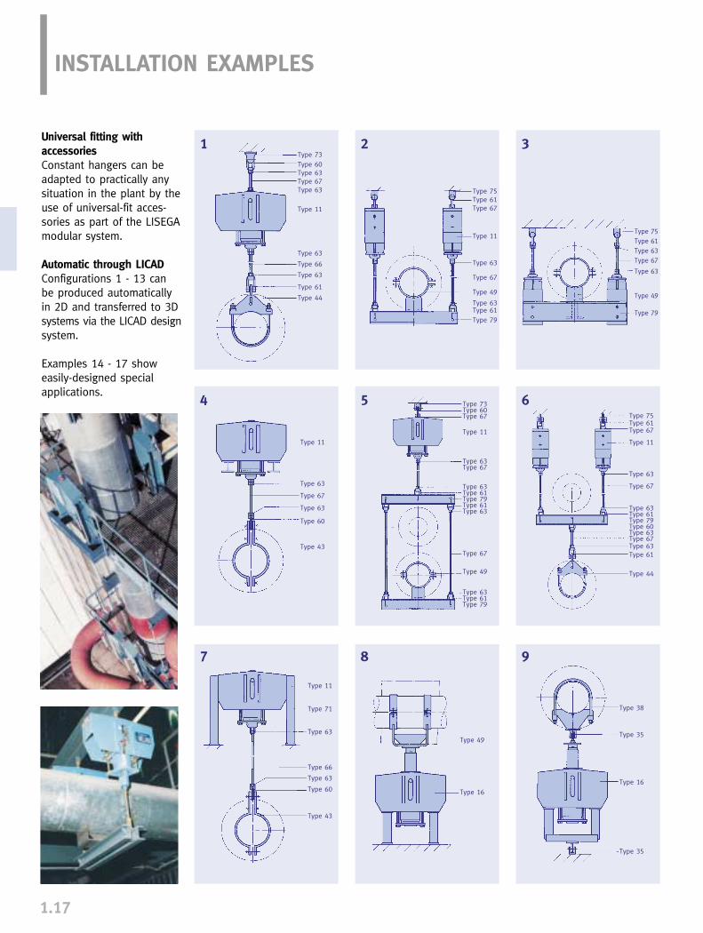
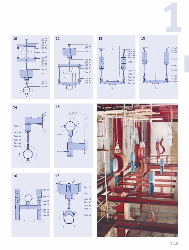
INSTALLATION EXAMPLES
Universal fitting with accessoriesConstant hangers can beadapted to practically anysituation in the plant by theuse of universal-fit acces-sories as part of the LISEGAmodular system.
Automatic through LICADConfigurations 1 - 13 can be produced automaticallyin 2D and transferred to 3Dsystems via the LICAD designsystem.
Examples 14 - 17 showeasily-designed special applications.
Typ 38
1 2 3
4 5 6
7 8 9
Type 73Type 60Type 63Type 67Type 63
Type 11
Type 63
Type 66
Type 63
Type 61
Type 44
Type 75Type 61Type 67
Type 11
Type 63
Type 67
Type 49
Type 63Type 61Type 79
Type 75Type 61Type 63Type 67
Type 63
Type 49
Type 79
Type 75Type 61Type 67
Type 11
Type 63
Type 67
Type 63Type 61Type 79Type 60Type 63Type 67Type 63Type 61
Type 44
Type 11
Type 63
Type 67
Type 63
Type 60
Type 43
Type 73Type 60Type 67
Type 11
Type 63Type 67
Type 63Type 61Type 79Type 61Type 63
Type 67
Type 49
Type 63Type 61Type 79
Type 11
Type 71
Type 63
Type 66
Type 63
Type 60
Type 43
Type 49
Type 16
Type 38
Type 35
Type 16
Type 35
1.18
1
17
10
14
12 1311
16
15
Typ 48
Type 73Type 60Type 67Type 61Type 79Type 61Type 63
Type 67
Type 63Type 61Type 79Type 61Type 63Type 67
Type 63
Type 11
Type 67Type 60
Type 43
Type 73Type 60Type 67
Type 11
Type 63Type 67Type 63Type 61Type 79Type 61Type 63
Type 67
Type 63Type 61Type 48
Type 73Type 60Type 63Type 66Type 63
Type 11
Type 63
Type 67
Type 63
Type 61
Type 46
Type 75Type 61Type 67
Type 11
Type 63
Type 66
Type 63
Type 61Type 48
Type 11
Type 63
Type 66
Type 63
Type 60
Type 43
Type 49
Type 16
Type 11
Type 49
Type 63
Type 67
Type 74Type 63
Type 71
Type 71
Type 11
Type 63
Type 67
Type 63
Type 61
Type 44
1.19
➜ unpredictable random influences on pipe statics
➜ differences between theoretical and actual values of load distribution
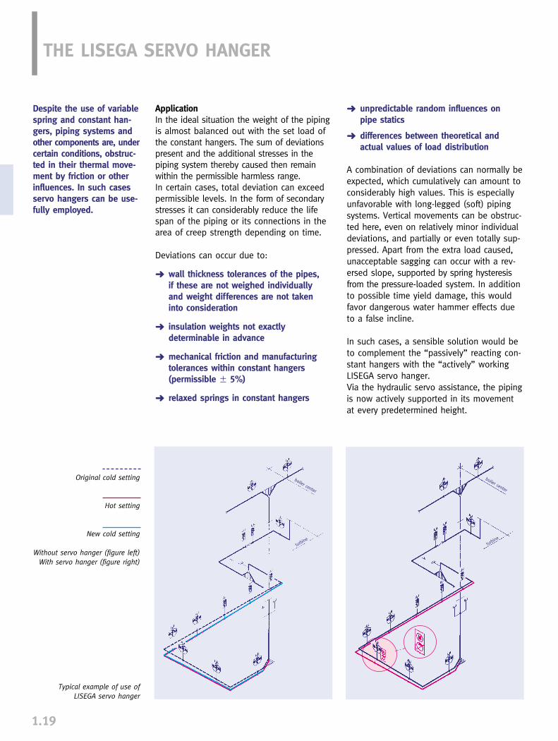
A combination of deviations can normally beexpected, which cumulatively can amount toconsiderably high values. This is especiallyunfavorable with long-legged (soft) pipingsystems. Vertical movements can be obstruc-ted here, even on relatively minor individualdeviations, and partially or even totally sup-pressed. Apart from the extra load caused,unacceptable sagging can occur with a rev-ersed slope, supported by spring hysteresisfrom the pressure-loaded system. In additionto possible time yield damage, this wouldfavor dangerous water hammer effects dueto a false incline.
In such cases, a sensible solution would beto complement the “passively” reacting con-stant hangers with the “actively” workingLISEGA servo hanger.Via the hydraulic servo assistance, the pipingis now actively supported in its movementat every predetermined height.
THE LISEGA SERVO HANGER
ApplicationIn the ideal situation the weight of the pipingis almost balanced out with the set load ofthe constant hangers. The sum of deviationspresent and the additional stresses in thepiping system thereby caused then remainwithin the permissible harmless range.In certain cases, total deviation can exceedpermissible levels. In the form of secondarystresses it can considerably reduce the lifespan of the piping or its connections in thearea of creep strength depending on time.
Deviations can occur due to:
➜ wall thickness tolerances of the pipes, if these are not weighed individually and weight differences are not taken into consideration
➜ insulation weights not exactly determinable in advance
➜ mechanical friction and manufacturing tolerances within constant hangers (permissible � 5%)
➜ relaxed springs in constant hangers
Original cold setting
Hot setting
New cold setting
Without servo hanger (figure left)With servo hanger (figure right)
Despite the use of variablespring and constant han-gers, piping systems andother components are, undercertain conditions, obstruc-ted in their thermal move-ment by friction or otherinfluences. In such casesservo hangers can be use-fully employed.
Typical example of use of LISEGA servo hanger
boiler center
turbine
turbine
boiler center
1.20
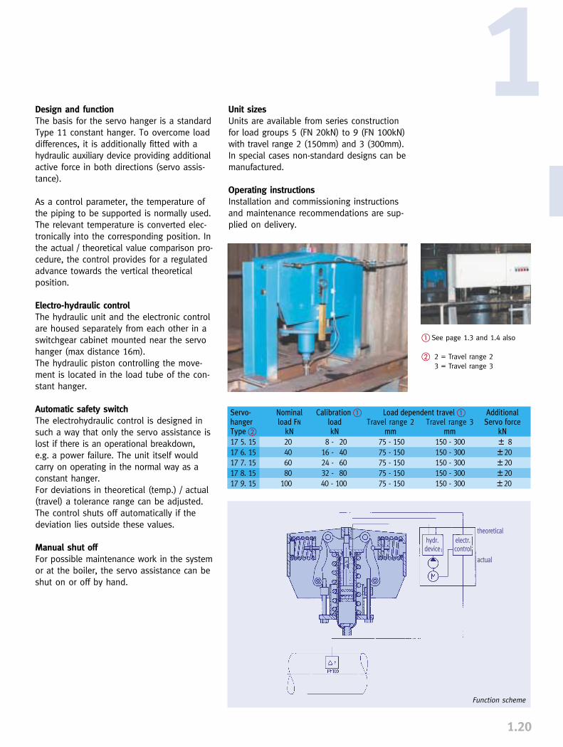
1Unit sizesUnits are available from series constructionfor load groups 5 (FN 20kN) to 9 (FN 100kN)with travel range 2 (150mm) and 3 (300mm).In special cases non-standard designs can bemanufactured.
Operating instructionsInstallation and commissioning instructionsand maintenance recommendations are sup-plied on delivery.
Design and functionThe basis for the servo hanger is a standardType 11 constant hanger. To overcome loaddifferences, it is additionally fitted with ahydraulic auxiliary device providing additionalactive force in both directions (servo assis-tance).
As a control parameter, the temperature ofthe piping to be supported is normally used.The relevant temperature is converted elec-tronically into the corresponding position. Inthe actual / theoretical value comparison pro-cedure, the control provides for a regulatedadvance towards the vertical theoreticalposition.
Electro-hydraulic controlThe hydraulic unit and the electronic controlare housed separately from each other in aswitchgear cabinet mounted near the servohanger (max distance 16m).The hydraulic piston controlling the move-ment is located in the load tube of the con-stant hanger.
Automatic safety switchThe electrohydraulic control is designed insuch a way that only the servo assistance islost if there is an operational breakdown, e.g. a power failure. The unit itself wouldcarry on operating in the normal way as aconstant hanger.For deviations in theoretical (temp.) / actual(travel) a tolerance range can be adjusted.The control shuts off automatically if thedeviation lies outside these values.
Manual shut offFor possible maintenance work in the systemor at the boiler, the servo assistance can beshut on or off by hand.
� See page 1.3 and 1.4 also
� 2 = Travel range 23 = Travel range 3
Function scheme
hydr.device
electr.control
theoretical
actual
Servo- Nominal Calibration � Load dependent travel � Additionalhanger load FN load Travel range 2 Travel range 3 Servo forceType � kN kN mm mm kN
17 5. 15 20 8 - 20 75 - 150 150 - 300 � 817 6. 15 40 16 - 40 75 - 150 150 - 300 � 2017 7. 15 60 24 - 60 75 - 150 150 - 300 � 2017 8. 15 80 32 - 80 75 - 150 150 - 300 � 2017 9. 15 100 40 - 100 75 - 150 150 - 300 � 20
1.21
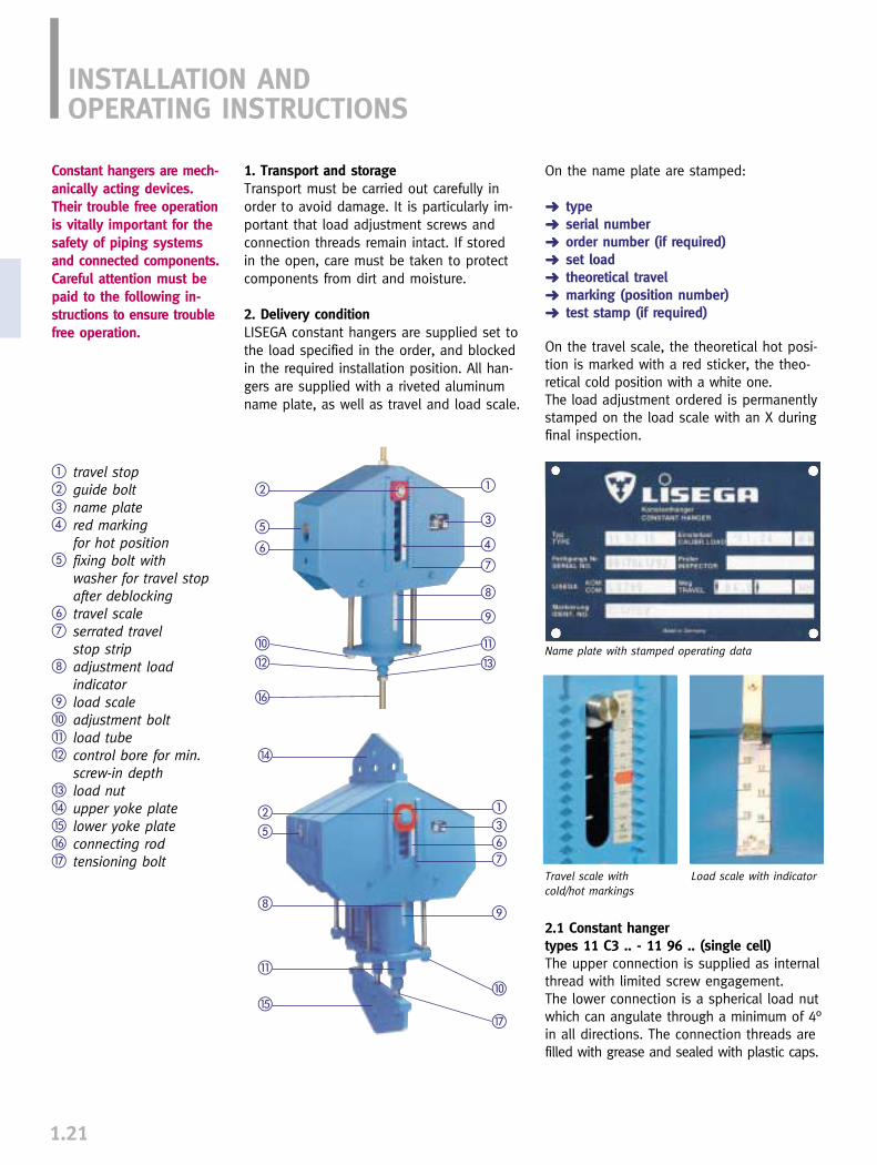
On the name plate are stamped:
➜ type➜ serial number➜ order number (if required)➜ set load➜ theoretical travel➜ marking (position number)➜ test stamp (if required)
On the travel scale, the theoretical hot posi-tion is marked with a red sticker, the theo-retical cold position with a white one. The load adjustment ordered is permanentlystamped on the load scale with an X duringfinal inspection.
INSTALLATION ANDOPERATING INSTRUCTIONS
Constant hangers are mech-anically acting devices.Their trouble free operationis vitally important for thesafety of piping systemsand connected components.Careful attention must bepaid to the following in-structions to ensure troublefree operation.
1. Transport and storageTransport must be carried out carefully inorder to avoid damage. It is particularly im-portant that load adjustment screws andconnection threads remain intact. If storedin the open, care must be taken to protectcomponents from dirt and moisture.
2. Delivery conditionLISEGA constant hangers are supplied set tothe load specified in the order, and blockedin the required installation position. All han-gers are supplied with a riveted aluminumname plate, as well as travel and load scale.
� travel stop� guide bolt� name plate� red marking
for hot position� fixing bolt with
washer for travel stop after deblocking
� travel scale� serrated travel
stop strip adjustment load
indicator load scale� adjustment bolt� load tube control bore for min.
screw-in depth� load nut� upper yoke plate� lower yoke plate� connecting rod� tensioning bolt
��
�
��
��
�� �
�
�
�
�
�
�
�
�
�
�
Name plate with stamped operating data
Travel scale with cold/hot markings
Load scale with indicator
�
�
2.1 Constant hangertypes 11 C3 .. - 11 96 .. (single cell)The upper connection is supplied as internalthread with limited screw engagement. The lower connection is a spherical load nutwhich can angulate through a minimum of 4°in all directions. The connection threads arefilled with grease and sealed with plastic caps.
2.2 Constant hangertypes 12 82 - 14 96 (multi cells)The upper connection is provided as standardin the form of a lug for a connecting pin.The lower attachment exists of several ten-sioning bolts connected by a yoke plate.
2.3 Constant hangers (seated)Constant hangers of all sizes can be directlyseated. They can also be supplied with serial-ized brackets type 71. The brackets can bebolted on at works or on site according toorder using the precision fit holes provided.The base plates of the mountings can be eitherwelded or bolted to the mounting surface.
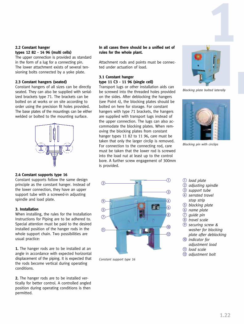
2.4 Constant supports type 16Constant supports follow the same designprinciple as the constant hanger. Instead ofthe lower connection, they have an uppersupport tube with a screwed-in adjustingspindle and load plate.
3. InstallationWhen installing, the rules for the InstallationInstructions for Piping are to be adhered to.Special attention must be paid to the desiredinstalled position of the hanger rods in thewhole support chain. Two possibilities areusual practice:
1. The hanger rods are to be installed at anangle in accordance with expected horizontaldisplacement of the piping. It is expected thatthe rods become vertical during operatingconditions.
2. The hanger rods are to be installed ver-tically for better control. A controlled angledposition during operating conditions is thenpermitted.
In all cases there should be a unified set ofrules for the whole plant.
Attachment rods and points must be connec-ted under actuation of load.
3.1 Constant hangertype 11 C3 - 11 96 (single cell)Transport lugs or other installation aids canbe screwed into the threaded holes providedon the sides. After deblocking the hangers(see Point 4), the blocking plates should bebolted on here for storage. For constanthangers with type 71 brackets, the hangersare supplied with transport lugs instead ofthe upper connection. The lugs can also ac-commodate the blocking plates. When rem-oving the blocking plates from constanthanger types 11 82 to 11 96, care must betaken that only the larger circlip is removed.For connection to the connecting rod, caremust be taken that the lower rod is screwedinto the load nut at least up to the controlbore. A further screw engagement of 300mmis provided.
1.22
1
� load plate� adjusting spindle� support tube� serrated travel
stop strip� blocking plate� name plate� guide pin travel scale securing screw &
washer for blockingplate after deblocking
� indicator for adjustment load
� load scale adjustment bolt
�
�
�
�
�
�
�
�
�
Blocking plate bolted laterally
Blocking pin with circlips
Constant support type 16
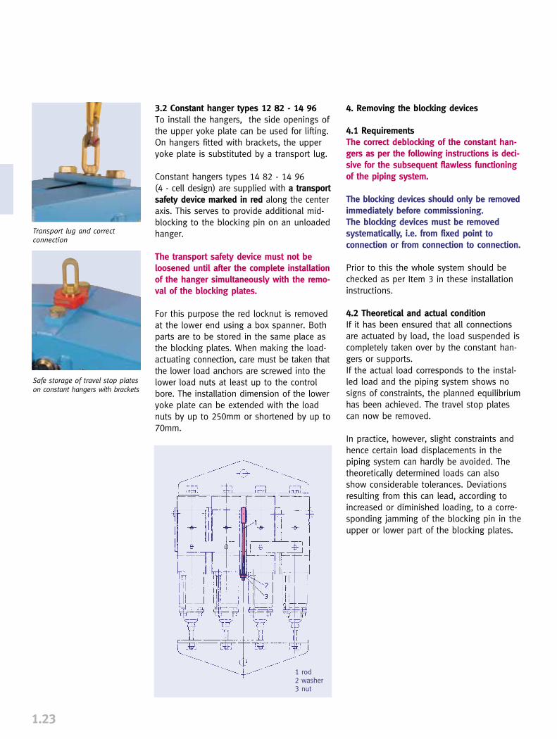
3.2 Constant hanger types 12 82 - 14 96To install the hangers, the side openings ofthe upper yoke plate can be used for lifting.On hangers fitted with brackets, the upperyoke plate is substituted by a transport lug.
Constant hangers types 14 82 - 14 96(4 - cell design) are supplied with a transportsafety device marked in red along the centeraxis. This serves to provide additional mid-blocking to the blocking pin on an unloadedhanger.
The transport safety device must not be loosened until after the complete installationof the hanger simultaneously with the remo-val of the blocking plates.
For this purpose the red locknut is removedat the lower end using a box spanner. Bothparts are to be stored in the same place asthe blocking plates. When making the load-actuating connection, care must be taken thatthe lower load anchors are screwed into thelower load nuts at least up to the controlbore. The installation dimension of the loweryoke plate can be extended with the loadnuts by up to 250mm or shortened by up to70mm.
1.23
4. Removing the blocking devices
4.1 RequirementsThe correct deblocking of the constant han-gers as per the following instructions is deci-sive for the subsequent flawless functioningof the piping system.
The blocking devices should only be removedimmediately before commissioning. The blocking devices must be removedsystematically, i.e. from fixed point toconnection or from connection to connection.
Prior to this the whole system should bechecked as per Item 3 in these installationinstructions.
4.2 Theoretical and actual conditionIf it has been ensured that all connectionsare actuated by load, the load suspended iscompletely taken over by the constant han-gers or supports. If the actual load corresponds to the instal-led load and the piping system shows nosigns of constraints, the planned equilibriumhas been achieved. The travel stop platescan now be removed.
In practice, however, slight constraints andhence certain load displacements in thepiping system can hardly be avoided. Thetheoretically determined loads can alsoshow considerable tolerances. Deviationsresulting from this can lead, according toincreased or diminished loading, to a corre-sponding jamming of the blocking pin in theupper or lower part of the blocking plates.
Transport lug and correctconnection
Safe storage of travel stop plateson constant hangers with brackets
1 rod2 washer3 nut
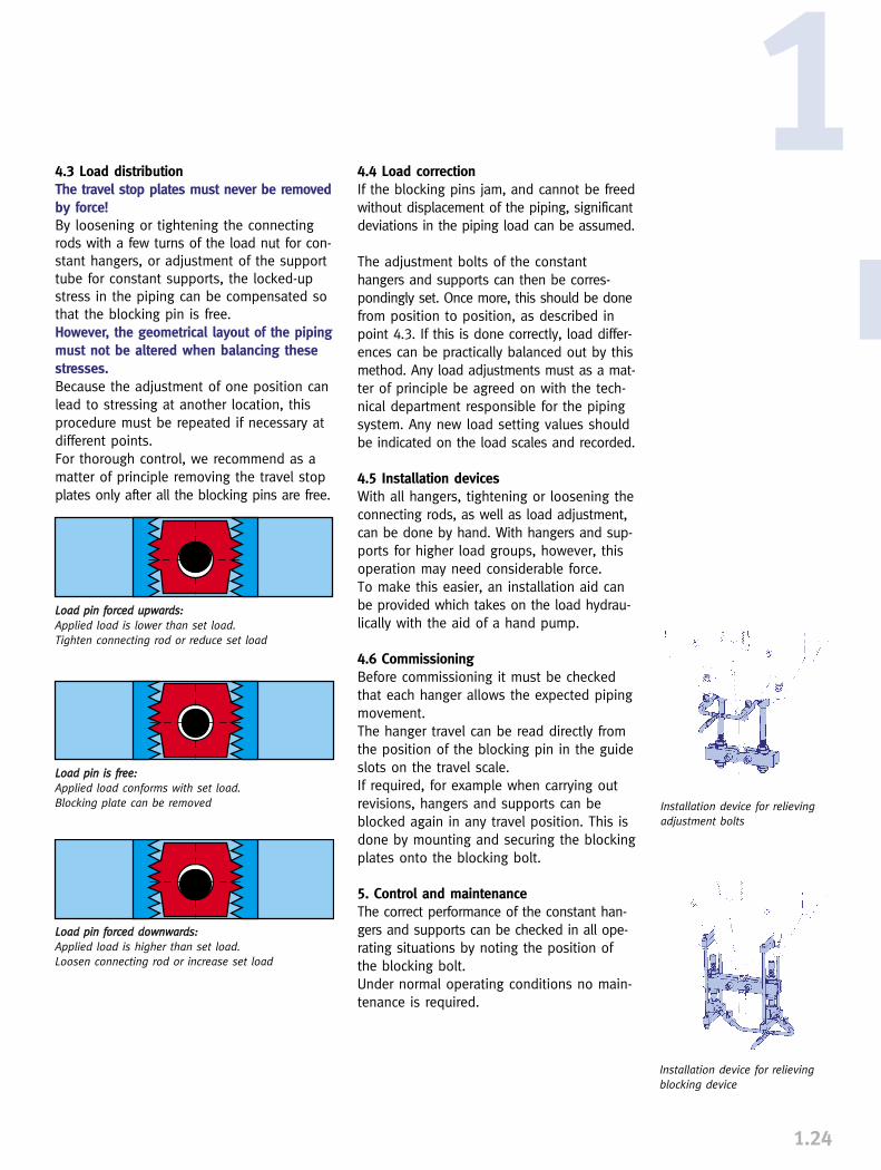
4.3 Load distributionThe travel stop plates must never be removedby force!By loosening or tightening the connectingrods with a few turns of the load nut for con-stant hangers, or adjustment of the supporttube for constant supports, the locked-upstress in the piping can be compensated sothat the blocking pin is free.However, the geometrical layout of the pipingmust not be altered when balancing thesestresses.Because the adjustment of one position canlead to stressing at another location, thisprocedure must be repeated if necessary atdifferent points.For thorough control, we recommend as amatter of principle removing the travel stopplates only after all the blocking pins are free.
1.24
1
LLooaadd ppiinn ffoorrcceedd uuppwwaarrddss::Applied load is lower than set load.Tighten connecting rod or reduce set load
LLooaadd ppiinn iiss ffrreeee::Applied load conforms with set load.Blocking plate can be removed
LLooaadd ppiinn ffoorrcceedd ddoowwnnwwaarrddss::Applied load is higher than set load.Loosen connecting rod or increase set load
4.4 Load correctionIf the blocking pins jam, and cannot be freedwithout displacement of the piping, significantdeviations in the piping load can be assumed.
The adjustment bolts of the constant hangers and supports can then be corres-pondingly set. Once more, this should be donefrom position to position, as described inpoint 4.3. If this is done correctly, load differ-ences can be practically balanced out by thismethod. Any load adjustments must as a mat-ter of principle be agreed on with the tech-nical department responsible for the pipingsystem. Any new load setting values shouldbe indicated on the load scales and recorded.
4.5 Installation devicesWith all hangers, tightening or loosening theconnecting rods, as well as load adjustment,can be done by hand. With hangers and sup-ports for higher load groups, however, thisoperation may need considerable force. To make this easier, an installation aid canbe provided which takes on the load hydrau-lically with the aid of a hand pump.
4.6 CommissioningBefore commissioning it must be checkedthat each hanger allows the expected pipingmovement.The hanger travel can be read directly fromthe position of the blocking pin in the guideslots on the travel scale.If required, for example when carrying outrevisions, hangers and supports can beblocked again in any travel position. This isdone by mounting and securing the blockingplates onto the blocking bolt.
5. Control and maintenanceThe correct performance of the constant han-gers and supports can be checked in all ope-rating situations by noting the position ofthe blocking bolt.Under normal operating conditions no main-tenance is required.
Installation device for relievingadjustment bolts
Installation device for relievingblocking device


