21

University of LeedsSCHOOL OF COMPUTER STUDIESRESEARCH REPORT SERIESReport 97.29A Comparison of Constraint Representation SchemesbySteven Carden & Peter Dew1June 1997
1Virtual Working Environment Group, Distributed Multimedia Systems Group

AbstractThe lack of a uni�ed framework for constraint problems has resulted in a diversityof constraint solution techniques and methods for describing constraint problems. Auni�ed framework would allow the construction of a kernel constraint engine, capableof solving constraint problems composed of models from di�erent domains, such asengineering and geometric problems. As a �rst step towards such a uni�ed framework,a uni�ed constraint representation scheme is necessary.This report presents reductions, a method of comparing constraint representationschemes in terms of expressiveness. A hierarchy of current constraint representationschemes can then be constructed. The notion of a generic constraint representationscheme is also introduced and a generic scheme is a potential candidate to be used asa uni�ed constraint representation scheme. Reductions are used to prove that certaincurrently used schemes are, in fact, generic.1 IntroductionConstraints have proved an important method for describing many problems in AI,such as scheduling, graph colouring and boolean satis�ability [6, 10]. In the �eld ofengineering design, constraints are also being used as a means of creating, describingand manipulating designs [7,11,13]. The Virtual Working Environment Group at theUniversity of Leeds has been studying constraint-based modeling, particularly usingconstraints as an intuitive means of specifying models within virtual environmentapplications [2,3,7,9,15]. Previous research work within the group was concentratedon developing a constraint engine for supporting interactive assembly modeling withina virtual environment (Fa et al [1, 3]). This work has focussed on geometric andassembly constraints, such as coincidence and concentricity, and is currently beingextended to support di�erent product life cycle stages such as conceptual design andmaintenance simulation. For example, Lamounier's work [7] studied the integrationof di�erent types of constraint problem, such as geometric and functional constraints,in order to describe and solve problems in the conceptual design and maintenancesimulation stages.So far, work at Leeds has concentrated on geometric [15] and functional [7] con-straints separately. Correspondingly, work has recently started on the integration ofdi�erent types of constraints. The purpose of this research is to develop a formalframework for handling varied types of constraints concurrently.In order to integrate constraints, it is necessary to �nd a representation schemecapable of describing all types of constraints concurrently. Instead of concentratingon properties of speci�c types of constraints exclusively, research work was carriedout to examine generic methods of describing constraint problems by the authors ofthis report. As a result, a formal, mathematical de�nition of a generic constraintproblem has been developed and a de�nition for a generic constraint representationscheme has been proposed. In addition, reduction techniques have been devised as amethod of comparing constraint representation schemes and to prove if a scheme isgeneric. Reductions form the main contribution of this report. Reductions have beenused to compare constraint representation schemes and to identify generic constraintrepresentation schemes in the literature, such as [1,5,8,10,11,13,14,16].1
Constraint/Entity Graphs (this paper)
GENERIC
CRSs
INFINITE-DOMAIN PROBLEMS
FINITE-DOMAIN PROBLEMS
Key
Indicates direction of
reduction
Directed Constraint Graphs (Fa [1])
Bipartite Representation (Latham & Middleditch [8] and Tsang [16])
Hypergraph Representation (Serrano & Gossard [13] and Tsang [16])
Undirected Constraint Graphs (Smith [14], Tsang [16], Meseguer [10])
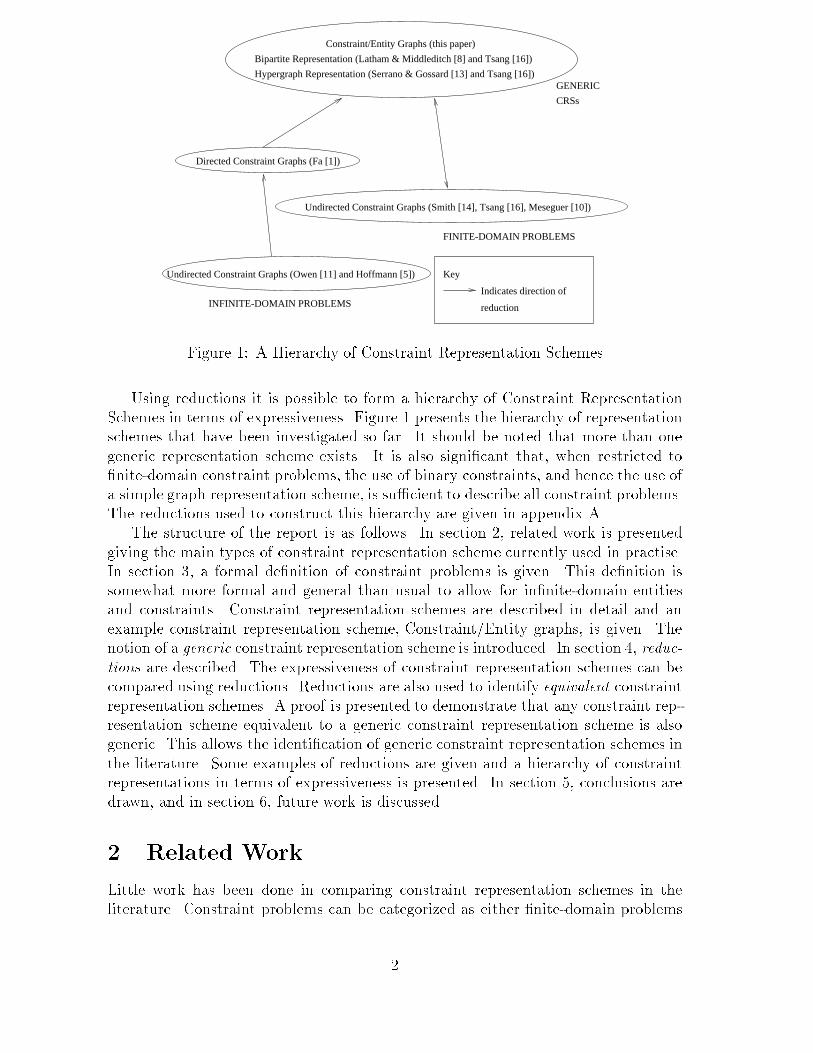
Undirected Constraint Graphs (Owen [11] and Hoffmann [5])Figure 1: A Hierarchy of Constraint Representation SchemesUsing reductions it is possible to form a hierarchy of Constraint RepresentationSchemes in terms of expressiveness. Figure 1 presents the hierarchy of representationschemes that have been investigated so far. It should be noted that more than onegeneric representation scheme exists. It is also signi�cant that, when restricted to�nite-domain constraint problems, the use of binary constraints, and hence the use ofa simple graph representation scheme, is su�cient to describe all constraint problems.The reductions used to construct this hierarchy are given in appendix A.The structure of the report is as follows. In section 2, related work is presentedgiving the main types of constraint representation scheme currently used in practise.In section 3, a formal de�nition of constraint problems is given. This de�nition issomewhat more formal and general than usual to allow for in�nite-domain entitiesand constraints. Constraint representation schemes are described in detail and anexample constraint representation scheme, Constraint/Entity graphs, is given. Thenotion of a generic constraint representation scheme is introduced. In section 4, reduc-tions are described. The expressiveness of constraint representation schemes can becompared using reductions. Reductions are also used to identify equivalent constraintrepresentation schemes. A proof is presented to demonstrate that any constraint rep-resentation scheme equivalent to a generic constraint representation scheme is alsogeneric. This allows the identi�cation of generic constraint representation schemes inthe literature. Some examples of reductions are given and a hierarchy of constraintrepresentations in terms of expressiveness is presented. In section 5, conclusions aredrawn, and in section 6, future work is discussed.2 Related WorkLittle work has been done in comparing constraint representation schemes in theliterature. Constraint problems can be categorized as either �nite-domain problems2

or in�nite-domain. The choice of �nite or in�nite domain a�ects the representationscheme chosen.Finite domain problems are typically described using simple constraint graphs asit has been proven that all �nite domain constraint problems can be described interms of binary constraints and simple graphs are su�cient for this purpose (see forexample [16]).In [16], Tsang discusses many aspects of �nite-domain constraint problems. Thedescription of constraint problems given presents constraints in terms of predicatelogic and labels. This is equivalent to the description given in this report, but thisreport covers in�nite-domain problems in more detail. Tsang also introduces severalconstraint representation schemes such as bipartite, simple and hypergraph graphrepresentation schemes. The bipartite and hypergraph schemes are similar to theConstraint/Entity graph of this report and the Constraint Network of [13] respec-tively.In [10], Meseguer describes constraints in terms of relations, but does not go intogreat detail as to how this may be extended to in�nite-domain problems. Smith [14]and Kumar [6] describe constraint problems similarly. All three restrict problems tovariables in �nite domains. All three assume that binary constraints are all that isneeded as n-ary constraints can be described as binary constraints.In�nite domain solvers typically use more complex techniques to describe prob-lems. In [1], Fa et al discuss ICBSM, the Interactive Constraint Based Solid Modeler.The description of constraint problems used in this context involves a set of 2D and3D objects in Euclidean space and constraints which represent geometric relationsbetween these entities. The representation scheme chosen is a directed, simple graphwith constraints as edges, which is known as a Relationship Graph. Tsai et al [15]have extended this work to allow for more advanced solutions and to allow constraintloops. Tsai retains Fa's Relationship Graph and the work has only been implementedfor 2D problems as yet.In [11], Owen uses a simpli�ed set of constraint problems, involving only a limitednumber of geometric constraints and objects. No �nite-domain entities are used,nor any complex engineering equations. Ho�mann and Juan [5] use a similar setof constraints and objects. The representation scheme chosen by both is a simplegraph, with the limitations discussed above. Latham and Middleditch [8] use a similarde�nition of constraint problems. However, they use a bipartite graph representationscheme, which is somewhat more general than the simple graph scheme.In [12,13], Serrano and Gossard describe constraint problems as a set of variablesand a set of constraints. The de�nition of constraints is somewhat vague, but isassumed here to be equivalent to the de�nition given in this report (section 3.2). Theconstraint problems are restricted to variables in one dimension and do not allowmore complex features or 3D shapes to be described as a single object and hencehave constraints act on such objects. Serrano and Gossard use two representationschemes - a bipartite graph and a hypergraph. Both are equivalent and turn out tobe generic, using the de�nition in this report. Lamounier et al [7] have improved onSerrano and Gossard's work by making the solution process incremental and thereforemore e�cient and appropriate for interactive use.3

3 Constraint ProblemsA characterization of constraint problems is desired that captures both the di�erenttypes of entities available, such as variables, geometries, times, etc and the di�erenttypes of constraints used, e.g. algebraic, geometric, scheduling. In order to describethe representation chosen, the terms entity, constraint, constraint problem and con-straint representation scheme are de�ned below. A thorough and strict de�nition ofthese terms allows identi�cation of the key structures that de�ne a constraint repre-sentation scheme.3.1 EntitiesDe�nition 1 (Entities) An entity is an object with a domain D. For example, anentity could be a variable in the real domain IR, or it could be a geometric object, forexample a sphere with �xed radius in 3D Euclidean space, IR3. A value for an entityis an instance in the domain of the entity. An assignation for an entity is a formulaof the form E = v, determining that entity E is to be assigned the value v in domainDE . The notation E = S denotes the fact that E is assigned a value in the set S.As examples of entities, consider the following equations:x2 + y2 = r2; x 2 IR; y 2 IR; r 2 IR+; (1)x+ y = b; x 2 IR; y 2 IR; b 2 IR: (2)Then the variables x; y; r and b are entities with domains, respectively, the realline, the real line, the positive real line and the real line. A value for x could be 3and an assignation of x to that value would be x = 3.3.2 ConstraintsDe�nition 2 (Relations) A relation,R, between a pair of entities a; b with domainsD1;D2 is a subset of the Cartesian product of the domains, D1 �D2. For (a; b) 2 R,the notation aRb is used. This representation is used for binary relations, however,the extension to n-ary relations is straight-forward. An n-ary relation, S, on a setof variables a1; : : : ; an with domains D1; : : : ;Dn is a subset of the Cartesian productD1 � � � � �Dn. For (a1; : : : ; an) 2 S, the notation S(a1; : : : ; an) is used.Since the sets de�ning a relation are typically in�nite, it is not usually possible toexplicitly list the members, and implicit means, such as set construction notation arenormally used.A useful de�nition of a relation is in terms of a test function. Each relationS(a1; : : : ; an) has a boolean test function f : D1�� � ��Dn �! f0; 1g associated withit, where f(x1; : : : ; xn) = 1 , (x1; : : : ; xn) 2 S. This de�nition is consistent withFra��ss�e [4].Examples of relations are:aRb , f(a; b) � a2 + b2 � 8 = 1;S(x; y; z) , g(x; y; z) � ax+ by + cz + d + 1 = 1;T (S1; C1) , S1 and C1 are coincident.4

De�nition 3 (Constraints) A constraint C on a set of entities E is a restrictionof the possible values that the entities in E can simultaneously take. A constraint Cis a relation on E. A tuple of values (v1; : : : ; vn) for entities (x1; : : : ; xn) satis�es aconstraint C if (v1; : : : ; vn) 2 C:Associated with every constraint is a constraint test procedure. A constraint testprocedure (CTP) for a constraint C with respect to a set of entities fx1; : : : ; xng withdomains D1; : : : ;Dn, is the boolean function fC : D1� � � ��Dn �! f0; 1g associatedwith C such that fC(v1; : : : ; vn) = 1, (v1; : : : ; vn) 2 C.3.3 Constraint ProblemsDe�nition 4 (Constraint Problems) A constraint problem is a pair (�;), where� is a set of entities and is a set of constraints.A solution to a constraint problem is a set of values that the entities in the problemtake simultaneously such that all of the constraints in the problem are satis�ed. Thisis formalised below.De�nition 5 (Solutions) A con�guration of problem P is a set of assignations forall of the entities in �. Con�guration fx1 = y1; : : : ; xn = yng is a solution to aconstraint problem P = (� = fx1; : : : ; xng;) if and only if(y1; : : : ; yn) 2 \C2C;or, equivalently, C2 fC(y1; : : : ; yn) = 1;where fC is the CTP for constraint C.Together equations 1 and 2 form a constraint problem,P = �fx; y; r; bg; fx2+ y2 = r2; x+ y = bg�with solutions f(x; y; r; b) j �x2 + y2 = r2� ^ (x+ y = b)g:An example con�guration for P could befx = 1; y = 2; r = 3; b = 4g :Note that the con�guration does not need to be a solution to the problem.5

3.4 Imposed SetsA constraint C is a subset of the Cartesian Product of the domains of the entitiesdescribing C. Each constraint is typically described in a local sense, in that eachconstraint is usually only described by a subset of the total set of entities E. However,a constraint problem will have more than one constraint usually, and each constraintwill have a di�erent set of entities relevant to it. What then are the solutions to twoconstraints? Since the entities relevant to each constraint are di�erent, there is noway of taking the intersection of the two constraints, which is the obvious means of�nding the solutions of two constraints.For example, consider the problem P consisting of three �nite-domain entities,x; y; z with domains f0; 1g and two constraints A and B de�ned byxAy , x = y;yBz , y 6= z:Then what are the solutions to P ? If A and B are enumerated explicitly, thenA = f(0; 0); (1; 1)g;B = f(1; 0); (0; 1)g:However, the intersection of these sets is ;. Clearly, there are solutions for P , fx =1; y = 1; z = 0g is one. If constraint C is de�ned with respect to E and not justthe set of entities that a�ect it, then it is possible to take the intersection of theconstraints.De�nition 6 (Enhanced Constraints) If the set of entities not relevant to C isEC , then the enhanced constraint C with respect to E, CjE, isCjE = C �DEC ;where DEC is the Cartesian Product of the domains of EC .For the example above then, EA = fzg;EB = fxg;and the enhanced constraints areAjE = f(0; 0); (1; 1)g � f0; 1g= f(0; 0; 0); (0; 0; 1); (1; 1; 0); (1; 1; 1)g;BjE = f(1; 0); (0; 1)g � f0; 1g= f(1; 0; 0); (1; 0; 1); (0; 1; 0); (0; 1; 1)g:However, the intersection of AjE and BjE is still ;. The reason for this is that AjE andBjE are arranged in di�erent orders. AjE is in the order x; y; z, whilst BjE is in theorder y; z; x. In order for the intersection to make sense, they must both have the sameordering of variables. In order to ensure this, we enforce a lexicographic ordering, <lex6

on the Cartesian Products, so that, in the example above, with lexicographic ordering<lex= x < y < z, AjE<lex = ff(0; 0); (1; 1)g � f0; 1gg= f(0; 0; 0); (0; 0; 1); (1; 1; 0); (1; 1; 1)g;BjE<lex = ff0; 1g � f(1; 0); (0; 1)gg= f(0; 1; 0); (0; 0; 1); (1; 1; 0); (1; 0; 1)g:Clearly the intersection of AjE and BjE is sensible and the result,f(1; 1; 0); (0; 0; 1)g;is the set of all solutions to P and using <lex, the assignations for x; y; z can simplybe read o�. It only remains to clear up some of the terminology and make theseconcepts formal. For simplicity, it is assumed that all constraints in P are enhancedconstraints with respect to E. The lexicographic ordering on Cartesian products willbe assumed from now on and omitted for clarity.De�nition 7 (Imposed Entities) A constraint C is imposed on an entity xi withdomain D if and only if (v1; : : : ; vi�1; v; vi+1; : : : ; vn) 2 C )9u 2 D; such that (v1; : : : ; vi�1; u; vi+1; : : : ; vn) =2 C:The intuitive explanation of this is that the constraint C is imposed on xi if and onlyif varying the value of xi may violate the constraint.In fact, it is somewhat clearer to examine the negative statement. A constraint Cis not imposed on an entity xi with domain D if and only if(v1 : : : ; vi�1; v; vi+1; : : : ; vn) 2 C )8u 2 D; (v1; : : : ; vi�1; u; vi+1; : : : ; vn) 2 C:Thus, C is not imposed on xi if the value of xi does not really a�ect C. In this case,we need not include xi in our description of C as it is essentially super uous.In the example above, constraint AjE is imposed on x as (1; 1; 1) is in AjE, but(0; 1; 1) is not. However, AjE is not imposed on z as (0; 0; z) and (1; 1; z) are in AjE,whether z is 0 or 1.Normally constraints are described only in terms of the entities they are imposedon. There is thus a subset of fx1; : : : ; xng associated with each constraint consistingof the entities imposed on by the constraint. This subset is denoted by the symbol �.De�nition 8 (Imposed Sets) The set � for a constraint C is called the imposed setof C. In the example above, the imposed set of AjE, �AjE , is fx; yg and the imposedset of BjE is fy; zg.The size of � for a constraint C, j�j, is usually referred to as the arity of C (see, forexample [14]). A constraint is called unary if j�j = 1, binary if j�j = 2, etc. Intuitively,a unary constraint only a�ects and is a�ected by one entity, binary constraints a�ectand are a�ected by two entities, etc. Unary constraints are simply a restriction on thedomain of the imposed entity and as such are usually dealt with by pre-processing.7

Since a constraint C is normally only described in terms of the imposed set of C,�C , it is important that �C is known for each C. Since the lexicographic ordering for�C is also important, this too is associated with each constraint. The set of partialorderings for each constraint must not be contradictory. This will ensure that a totalordering can be created and that the enhanced constraints can be de�ned.3.5 Constraint Representation SchemesA constraint representation scheme (CRS) is a method of describing a constraint prob-lem, typically using graph techniques. A CRS should be such that, given a problem inthe CRS, no more information is needed to examine, understand and attempt to solvethat problem, other than that provided by the scheme. A problem in a valid CRSwill therefore always be well-posed in the sense that there is su�cient information tosolve the problem given that a solution exists. Thus, objects representing constraintswould be linked to the actual constraints themselves in some way and objects repre-senting entities would be linked to the actual entities. Having examined several CRSsin the literature with respect to the very formal framework for the constraint problemde�ned above, it is apparent that there exists a common set of properties that a CRSshould have.De�nition 9 (Constraint Representation Schemes) A Constraint Representa-tion Scheme should satisfy all of the following properties:1. There should be an identi�able set of entities, together with their domains;2. There should be an identi�able set of constraints, with a constraint test proce-dure, imposed set and lexicographic ordering associated with each constraint;3. There is a `connection' between a subset of entities if and only if there is aconstraint imposed on the subset;4. There should be a one-to-one correspondence between the constraints and theconnections in the representation;5. There should be a de�nition of what a solution in the representation looks like.The de�nition of `connection' will vary from scheme to scheme. For example in theconstraint graph representation of Owen [11], a connection is just an edge, whilst inthe Constraint/Entity graph representation of this report (section 3.7), a connectionis the set of edges incident to a particular constraint vertex.De�nition 10 (Generic Representation Schemes) A generic CRS is a CRS inwhich every constraint problem can be described, where a constraint problem is asin section 3.3. A generic constraint representation scheme will be useful as it can beused to describe all problems that will be encountered.8

y
Dy
x
Dx
z
Dz
w
Dw
f (x,y,z)A
B
A
C
f (z,w)B
Cf (x,y)
1
1 2
2
3
1 2Figure 2: Example of a Constraint/Entity Graph3.6 Algebraic RepresentationThe algebraic representation of a constraint problem is the pair (E; C), where E =f(x1;D1); : : : ; (xn;Dn)g is the set of entities with domains and the set C = f(c1; fc1;�c1 ; <c1); : : : ; (cm; fcm ; �cm ; <cm)g is the set of constraints, where fci is the ConstraintTest Procedure for constraint ci and �ci is the imposed set of constraint ci.A connection between elements of F � E exists i� 9ci 2 C such that �ci = F . Then-tuple (v1; : : : ; vn) is a solution of an algebraic representation i�8ci 2 C; �f 0ci(v1; : : : ; vn) = 1� ^ (8j; vj 2 Dj) ;where f 0ci(v1; : : : ; vn) = fci(vi1; : : : ; vim);�ci = fxi1; : : : ; ximg;and xi1 <ci xi2 <ci � � � <ci xim:From here, notation will be abused so that fci is equivalent to f 0ci .Given the de�nition of generic CRSs in section 3.5, the algebraic representationscheme above is generic.3.7 The Constraint/Entity Graph RepresentationThe Constraint/Entity graph (C/E graph) is a labelled, undirected, bipartite, con-nected graph (C; V;E) with two types of vertices: constraints and entities. A bipar-tite graph is a graph (V;E) such that V = U [ W , U \ W = ; and 8(a; b) 2 E,(a 2 U ^ b 2 W ). Note that the Constraint/Entity representation is adapted fromthe bipartite representations used by Serrano [12] and Latham and Middleditch [8].An example Constraint/Entity graph is given in �gure 2.9
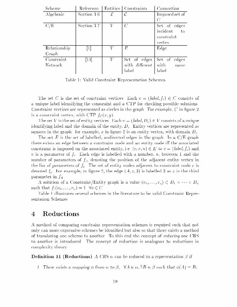
Scheme Reference Entities Constraints ConnectionAlgebraic Section 3.6 E C Imposed set ofCC/E Section 3.7 V C Set of edgesincident toconstraintvertexRelationshipGraph [1] V E EdgeConstraintNetwork [13] V Set of edgeswith di�erentlabel Set of edgeswith samelabelTable 1: Valid Constraint Representation SchemesThe set C is the set of constraint vertices. Each c = (label; fc) 2 C consists ofa unique label identifying the constraint and a CTP for checking possible solutions.Constraint vertices are represented as circles in the graph. For example, C in �gure 2is a constraint vertex, with CTP fC(x; y).The set V is the set of entity vertices. Each v = (label;Dv) 2 V consists of a uniqueidentifying label and the domain of the entity, Dv. Entity vertices are represented assquares in the graph. for example, x in �gure 2 is an entity vertex, with domain Dx.The set E is the set of labelled, undirected edges in the graph. In a C/E graphthere exists an edge between a constraint node and an entity node i� the associatedconstraint is imposed on the associated entity, i.e. (c; v; n) 2 E , c = (label; fc) andv is a parameter of fc. Each edge is labelled with a number, n, between 1 and thenumber of parameters of fc, denoting the position of the adjacent entity vertex inthe list of parameters of fc. The set of entity nodes adjacent to constraint node c isdenoted �c. For example, in �gure 2, the edge (A; z; 3) is labelled 3 as z is the thirdparameter in fA.A solution of a Constraint/Entity graph is a value (v1; : : : ; vn) 2 D1 � � � � � Dnsuch that fc(v1; : : : ; vn) = 1 8c 2 C.Table 1 illustrates several schemes in the literature to be valid Constraint Repre-sentation Schemes.4 ReductionsA method of comparing constraint representation schemes is required such that notonly can more expressive schemes be identi�ed but also so that there exists a methodof translating one scheme to another. To this end the concept of reducing one CRSto another is introduced. The concept of reduction is analogous to reductions incomplexity theory.De�nition 11 (Reductions) A CRS � can be reduced to a representation � if1. There exists a mapping � from � to �; 8A 2 �;9B 2 � such that �(A) = B;10

2. Every solution of A is also a solution of B and every solution of B is also asolution of A. In other words A and B (the reduced problem) have the samesolutions;3. � and � are valid constraint representation schemes;4. The reduction can be done in polynomial time.The last criterion is necessary to ensure that the problem does not become in-tractable due to the reduction.Reductions form a tool by which it is possible to compare and contrast constraintrepresentation schemes in terms of their expressiveness.The intuitive notion of reductions is that any problem in � can be described in �,and that every solution of the reduced problem is a solution of the original problem.Thus the reduced problem is describing the same problem as the original. Since everyproblem in � can be described in �, � is capable of describing at least as manyproblems as � and possibly more. This is usually denoted by saying that � is at leastas powerful as �. It is natural therefore to wonder when two constraint representationschemes are equally powerful.De�nition 12 (Equivalent Constraint Representation Schemes) The tworepresentations � and � are equivalent if and only if � can be reduced to � and � canbe reduced to �. The notation � � � is used to denote equivalence.Since generic representation schemes are the goal of this paper, constraint representa-tion schemes that are equivalent to generic representation schemes will be particularlyimportant.Theorem 1 If � � � and � is generic, then � is genericProof If � � �, then 9� such that 8B 2 �;9A 2 �; �(B) = A. Hence B can bedescribed and solved in �, and since B is arbitrary, � is generic. 24.1 Algebraic Representation is equivalent to Constraint/Entity RepresentationTheorem 2 The Algebraic Representation is equivalent to the Constraint/ EntityRepresentation in the sense that every problem that can be described in the AlgebraicRepresentation can also be described in the Constraint/Entity Representation andvice versa.Proof The proof is in two parts. First a reduction is formed from the AlgebraicRepresentation to the Constraint/Entity Representation.A mapping is de�ned as follows:For every (xi;Di) 2 E, create (xi;Di) in V .For every (c; fc; �c; <c) 2 C, create (c; fc) in C.Create E such that ((c; fc); (x;Dx); n) 2 E , x 2 �c and x is inposition n in <c. 11

x
y
z
w
C
A
B
D
D
D
Dw
x
y
z
f (y,z,w)
f (x,w)
f (x,y,z)A
C
B
1
2
3
1
2
3
1
2Figure 3: Constraint/Entity Representation for Constraint Problem The resulting graph is obviously a Constraint/Entity graph. As an example,consider the simple constraint problem below. The Constraint/Entity graph resultingfrom the reduction is as in �gure 3. = (f(x;Dx); (y;Dy); (z;Dz); (w;Dw)g;f(A; fA; �A; <A); (B; fB; �B; <B); (C; fC; �C ; <C)g);such that �A = fx; y; zg; �B = fy; z; wg; �C = fx;wg;and <A= [x; y; z]; <B= [y; z; w]; <C= [x;w]:The entity vertices fx; y; z; wg, the constraint vertices fA;B;Cg and the edgesf(A;x; 1); (A; y; 2); (A; z; 3); (B; y;1); (B; z;2); (B;w; 3); (C; x;1); (C;w; 2)gare created. The reduction criterion are demonstrated below:1. Mapping is de�ned above.2. A solution (y1; : : : ; yn) of (E; C) is a solution of the Constraint/ Entity graphby the de�nition of a solution of the Constraint/ Entity graph and that of thealgebraic representation, and vice versa.3. Both are valid CRSs, by table 1.4. For every constraint in the constraint problem, a constraint vertex is created,taking O(m). For every entity in the constraint problem, an entity vertex iscreated, taking O(n). For every constraint in the constraint problem an edgefor each entity the constraint is imposed on is created, taking O(mn). Hencethe reduction is polynomial. 12

Secondly the reverse reduction, from a Constraint/Entity graph to the algebraicrepresentation, is proved, using the following mapping:Given Constraint/Entity graph (C; V;E), construct E = V . Construct�c for each c 2 C by �c = fxi1; xi2; : : : ; xikg;such that ((c; fc); (xij;Dxij ); n) 2 E. Then construct <c for each c 2 Cby x <c y , (c; x; n) 2 E and (c; y;m) 2 E and n < m:Then de�ne C = f(c; fc; �c; <c)j(c; fc) 2 Cg:Then the pair (E; C)is the algebraic representation as de�ned in section 3.6.The reduction criterion are now checked to make sure the reduction is valid.1. Map is de�ned above.2. By the de�nition of the solutions of a Constraint/Entity graph and in the alge-braic representation, the solutions are the same.3. Both are valid CRSs, from table 1.4. For each entity vertex in the C/E graph, an entity in E is created, taking O(n).For each constraint in the C/E graph, a constraint in C is created. There may beO(n) edges incident to each constraint and O(m) constraints, so reconstructingthe imposed sets is O(mn). Hence the reduction is polynomial.It is therefore concluded that the Algebraic Representation for constraint problemsis equivalent to the Constraint/Entity graph representation. This is as expected andmeans that every problem that can be described in terms of relations can be describedas a Constraint/Entity graph. So Constraint/Entity graphs are generic. 24.2 Relationship Graph is strictly less powerful than Con-straint/Entity RepresentationTheorem 3 The Relationship Graph [1] is strictly less powerful than the Constraint/Entity Graph Representation in the sense that not all problems that can be describedin the Constraint/Entity Representation can be described in the Relationship GraphRepresentation, but that all problems in the Relationship Graph Representation canbe described in the Constraint/Entity Representation.Proof The proof is in two parts. First a reduction is formed from the Relation-ship Graph to the Constraint/Entity representation, demonstrating that the Con-straint/Entity Graph is at least as powerful as the Relationship Graph. The Rela-tionship Graph is a directed graph, in which constraints are represented by directededges and entities are represented by circular vertices.The mapping used to reduce a directed constraint graph (V;E) to a C/E graph(VB; CB; EB) is as follows: 13

Cu v
D Du v
f (u,v)C
1 2Figure 4: New Construct for Constraint EdgesuC
Du
f (u)C
1Figure 5: New Construct for Constraint LoopsCreate VB = V .For each edge e in E, with CTP fe, create constraint vertex (e; fe) inCB.For each edge e = [u; v] in E, create edges (e; u; 1) and (e; v; 2) inEB. E�ectively, this means replacing all edges ((u;Du); (v;Dv)) with theconstruct in �gure 4, where ((u;Du); (v;Dv)) represents constraint C, with�C = fu; vg and <C= [u; v], C has CTP f . As edges in the RelationshipGraph are directed, there is an implicit ordering which is captured byhaving the edge from C to u labelled with a 1 and (C; v) labelled with a2. For each edge e = [u; u] in E, create edge (e; u; 1) in EB. E�ectivelythis means replacing all edges ((u;Du); (u;Du)) with the construct in �g-ure 5.The resultant graph is clearly a C/E graph. Checking the reduction criterion:1. The mapping is de�ned above.2. A solution to the constraint graph will result in values being assigned to thevarious entity vertices. The assignment of the same values to the entity verticesin the reduced C/E graph will form a solution to the C/E graph problem, sincethe same CTPs are used in both schemes.3. Both are valid CRSs, as in table 1.4. The reduction can be done in linear time in the number of edges in the constraintgraph. It is therefore polynomial time.So the relationship graph can be reduced to a C/E graph.Secondly, it is necessary to prove that Constraint/Entity graphs cannot be reducedto Relationship Graphs. This implies that Constraint/Entity graphs are strictly morepowerful than Relationship Graphs. The weakness of RGs lies in the fact that onlybinary and unary constraints can be described.14

Entity
Const
Entity
EntityEntity
1
2
3
4Figure 6: Representing Quaternary Constraints in a Constraint/Entity GraphIt is however possible to represent ternary or n-ary constraints in a Constraint/Entity graph by the number of edges e 2 E such that the constraint vertex is incidentto e (see �gure 6).Since more complex, non-geometric constraints will probably require n-ary con-straints, such a representation is clearly desirable.Since n-ary constraints, n � 3 cannot be described using a Relationship Graph,it is concluded that the Constraint/Entity representation is more powerful or moregeneral than Relationship Graphs. 25 ConclusionsThis report has presented reductions, a method for comparing constraint representa-tion schemes. Using reductions, it has been possible to form a hierarchy of constraintrepresentation schemes in terms of expressiveness (see �gure 1 for a hierarchy of cur-rent representation schemes). Also presented is the notion of a generic constraint rep-resentation scheme. Generic constraint representation schemes form a uni�ed frame-work for constraint representation schemes in the sense that any constraint problemcan be described using a generic constraint representation scheme. Reductions canbe used to identify generic constraint representation schemes.6 Future WorkFuture work will concentrate on a uni�ed framework for constraint solution tech-niques. It is hoped that a similar method to reductions can be developed for con-straint solution techniques and it will be possible to form a hierarchy of constraintsolution techniques. Research will also focus on the semantics of constraint solutionand will investigate the various techniques involved in solution of both �nite andin�nite-domain problems. Particular attention will be paid to the link between �niteand in�nite domain solution techniques. 15

AcknowledgmentsWe would like to acknowledge the valuable assistance of Russ Bubley and the membersof the Constraint Group within the Virtual Working EnvironmentGroup, particularlyEdgard Lamounier and Yung-Teng Tsai, in this work.A Further ReductionsThis appendix presents the details of the remaining reductions necessary to form thehierarchy of constraint representation schemes in �gure 1. They are:� Undirected graph �! directed graph� Bipartite graph ! hypergraph� Bipartite graph ! binary graph in �nite caseA.1 Undirected graphs are strictly less powerful than di-rected graphsTheorem 4 Undirected constraint graphs, for example those used by Owen [11] andErep [5], are strictly less powerful than the directed graphs used by, for exampleICBSM [1].Proof The proof is in two parts. First a reduction is formed from the undirectedconstraint graph to the directed constraint graph, demonstrating that the directedgraph can describe at least as many problems as the directed graph. Before de�ningthis reduction, the concept of symmetric relations is introduced as this has a directbearing on the discussion following.De�nition 13 (Symmetric Constraints) A constraint C is symmetric if the im-posed set on C is fxi1; : : : ; xijg, (vi1; : : : ; vij) are values in Di1 ; : : : ;Dij of xi1; : : : ; xijrespectively and (v1; : : : ; vi1; : : : ; vi2; : : : ; vij; : : : ; vn) 2 C )(v1; : : : ; �l(vi1); : : : ; �l(vi2); : : : ; �l(vij); : : : ; vn) 2 C;for all permutations �l of (vi1; : : : ; vij). A constraint is non-symmetric if it is notsymmetric.Intuitively, it is possible to order the entities in the imposed set of a symmetricconstraint in any way and they will still describe the same constraint. Examples ofsymmetric constraints are as follows x = y;Sphere1 against Cuboid13Examples of non-symmetric constraints arex+ y + z = a+ b;Drill before Screw16

The vast majority of constraints are non-symmetric. However, there are a signi�-cant number of symmetric geometric constraints and some constraint representationschemes, such as constraint graphs ( [5,11]) take advantage of this.The signi�cance of symmetric constraints is that the lexicographic ordering asso-ciated with the constraint is only a partial ordering. For example, for the constraintx = y, it does not matter which order we check x and y values in, the constraint isstill the same. Testing (3; 4) and (4; 3) gives the same result.In an undirected graph there is no concept of ordering of binary constraints.It is not therefore possible to describe anything but symmetric constraints and soit is assumed that all constraints in an undirected constraint graph are symmetricconstraints. It is this fact that will be exploited in this proof.The mapping used to reduce an undirected constraint graph (V;E) to a directedconstraint graph (VD; ED) is as follows:Create VD = V .For each edge e 2 E, choose an orientation of that edge randomly sothat, for example, (u; v) in the undirected graph becomes [v; u] 2. Placethe directed edge in ED.The resultant graph is clearly a directed constraint graph. Checking the reductioncriterion:1. The mapping is de�ned above.2. Since the constraints in the undirected graph are symmetric and both graphs usethe same CTP, any solution to the directed graph is a solution to the undirectedgraph. Similarly, any solution to the directed graph must be a solution of theundirected graph.3. Both are valid CRSs.4. The reduction can be done in linear time in the number of edges in the undi-rected constraint graph. It is therefore polynomial time.So the undirected graph can be reduced to a directed graph representation.Secondly, it is necessary to prove that the directed graph cannot be reduced tothe undirected graph. This implies that directed graph representations are strictlymore powerful than undirected graph representations as required. It su�ces to �nda counter example. The weakness of undirected graph representations is that theyrequire all of the constraints to be symmetric.Consider then, the following problem:P = (E;C);E = f(x; IR); (y; IR); (z; IR)g;C = fx < y; y = z; z < xg:There is an obvious directed graph representation of the problem, but no obvious undi-rected representation as the two constraints x < y and z < x are non-symmetric. It is2The square brackets are used to denote a directed edge, whereas normal brackets denote anundirected edge 17

necessary to retain an ordering in order to describe these constraint non-ambiguously.Since an undirected graph does not preserve order, not all problems that can be de-scribed using a directed graph can be described in an undirected constraint graphrepresentation. Thus, it is concluded that the directed graph representation is morepowerful than the undirected graph representation as desired. 2A.2 Bipartite graph schemes are equivalent to hypergraphrepresentation schemesTheorem 5 The bipartite graph CRSs, such as the Constraint/Entity graph in thisreport and the schemes of Tsang [16] and Middleditch and Latham [8], are equivalentto hypergraph representation schemes, such as Serrano's Connectivity Network [13].Proof Again the proof is in two parts. First a reduction is formed from a bipartitegraph representation scheme to a hypergraph representation scheme. The mappingused is as follows:Given the bipartite graph (C; V;E), create hypergraph (VH ;HE).For each vertex xi 2 V create entity vertex xi in VH .For each ci 2 C, construct �ci such that �ci = fxi1; xi2; : : : ; xikg, theset of entity vertices adjacent to ci in E. Then construct the hyperedgehe in HE, he = �ci ;labelled as constraint ci with CTP fci and ordering <ci .The resulting graph is obviously a hypergraph. Checking the reduction criterion.1. Map is de�ned above.2. Since the relation ci is borrowed and the ordering of the entities retained, thesame problem is being solved, so all solutions in the bipartite graph are solutionsin the hypergraph and vice versa.3. Both are valid CRSs.4. For each entity in E a vertex in the hypergraph is created, taking O(n). Foreach constraint in C one hyperedge is created, taking O(mn) in all. This is apolynomial time algorithm.Secondly, a reduction is formed from the hypergraph to the bipartite graph asfollows: Given the hypergraph (V;HE), create bipartite graph (VB; CB; EB).For each variable xi 2 V , construct entity vertex xi in VB.For each constraint ci 2 HE, construct a constraint vertex labeled ciin CB.Create edge (xi; cj; k); xi 2 VB; cj 2 CB; k 2 Z if he 2 HE;xi 2 he,cj 2 he and xi is in the kth position of <cj .The resultant graph is a bipartite graph. Checking the reduction criterion.18

1. Map de�ned above.2. Since the constraints are tested using the same test procedures in both repre-sentations, a solution in one will be a solution in the other.3. Both are valid CRSs.4. For each entity in V , an entity vertex in the bipartite graph is created, takingO(n). For each constraint in C, a constraint vertex in the bipartite graph iscreated, taking O(m). Each constraint is imposed on at most O(n) entities soat most O(n) edges per constraint are created, hence O(mn) in total. Hencethe reduction is polynomial.Hence the bipartite and hypergraph representation schemes are equivalent. 2A.3 Hypergraph representations and binary constraint graphrepresentations are equivalent for �nite domain prob-lemsTheorem 6 When dealing only with �nite domain problems, hypergraph graph rep-resentations and binary constraint graph representations are equivalent.Proof This is a proof oft-quoted in the literature, though not explicitly called areduction. It is usually discussed as a method of describing n-ary constraints insimple graphs, but can be interpreted as a reduction from a hypergraph representationscheme to a binary graph representation scheme (see Tsang [16], p12, for example).The reverse reduction is, of course, trivial, as binary graphs are already hypergraphs.2References[1] M. Fa, T. Fernando, and P. M. Dew. Interactive Constraint-based Solid Mod-elling using Allowable Motion. Proc. of ACM/SIGGRAPH Symposium on SolidModelling and Applications, pages 243{252, May 1993.[2] L.T.P. Fernando, P.M. Dew, and F. Gao. Constraint-based interaction tech-niques for supporting a distributed collaborative engineering environment. InProceedings of the First Workshop on Simulation and Interaction in Virtual En-vironments - SIVE '95, pages 265{270, 1995.[3] L.T.P. Fernando, M. Fa, P.M. Dew, and M. Munlin. Constraint-based 3d ma-nipulation techniques within virtual environments. In R.A. Earnshaw, editor,Virtual Reality Applications, pages 71{89. Academic Press, 1995.[4] R. Fra��ss�e. Theory of Relations, volume 118 of Studies in Logic and the Founda-tions of Mathematics. Elsevier Science Publishers, Amsterdam, 1986.[5] C.M. Ho�mann and R.Juan. Erep - An Editable, High-level Representationfor Geometric Design and Analysis. Technical report, Department of ComputerSciences, Purdue University, 1994. 19

[6] Vipin Kumar. Algorithms for Constraint-Satisfaction Problems: A Survey. AIMagazine, pages 32{44, Spring 1992.[7] E. Lamounier, T. Fernando, and P. Dew. An Incremental Constraint Equa-tion Solver for Variational Design. In Proceedings of the Fourth InternationalConference on Computational Graphics and Visualization Techniques (COM-PUGRAPHICS'95), pages 81{90, December 1995.[8] R. Latham and A. Middleditch. Connectivity Analysis : A Tool for ProcessingGeometric Constraints. Technical report, Brunel University, UK, August 1994.[9] J. Max�eld, L.T.P. Fernando, and P.M. Dew. A distributed virtual environmentfor collaborative engineering. In Proceedings Virtual Reality Annual InternationalSymposium - VRAIS'95, pages 162{170, 1995.[10] Pedro Meseguer. Constraint Satisfaction Problems: An Overview. AI Commu-nications, 2(1):3{17, March 1989.[11] J. Owen. Algebraic Solution for Geometry from Dimensional Constraints. Sym-posium on Solid Modelling Foundations and CAD/CAM Applications, June 1991.[12] David Serrano. Constraint Management in Conceptual Design. PhD thesis,Department of Mechanical Engineering, MIT, 1987.[13] David Serrano and David Gossard. Tools and Techniques for Conceptual Design.In Arti�cial Intelligence in Engineering Design, volume 1, chapter 3, pages 71{116. Academic Press, Inc, 1992.[14] Barbara Smith. A Tutorial on Constraint Programming. Technical Report 95-14,University of Leeds, April 1995.[15] Y. Tsai, T. Fernando, and P. Dew. Exploiting Degrees of Freedom Analysisfor Interactive Constraint-Based Design. In Fourth International Conference inCentral Europe on Computer Graphics and Visualization (WSCG'96), February1996. (to appear).[16] Edward Tsang. Foundations of Constraint Satisfaction. Academic Press, 1993.20


