Page 1
Constructing a filler network for thermal conductivity
enhancement in epoxy composites via reaction-induced phase
separation
Yuwei Zhanga, Yucai Shen
※a, Kunxiang Shi
a, Tingwei Wang
※a, Eileen
Harkin-Jonesb
aCollege of Materials Science and Engineering, Nanjing Tech University, Nanjing,
210009, China
bSchool of Engineering, University of Ulster, Jordanstown BT37 0QB, UK
Abstract
Diglycidyl ethers of bisphenol-A (DGEBA)/methyl tetrahydrophthalic
anhydride/polyethersulphone (PES) blends are prepared as matrix resins for thermally
conductive composites using graphite nanoplatelets (GNPs) as the conductive
component. The epoxy/PES blends form a network structure via reaction-induced phase
separation (RIPS) during the curing process, and the GNPs are selectively localized in
the PES phase and at the interface leading to a three-dimensional continuous filler
network. With this unique structure, the thermal conductivity of the epoxy/PES/10 wt%
GNPs composite is increased to 0.709 W m-1
K-1
, which is nearly 3.5 times that of the
pure epoxy or a 52% increase compared to the epoxy/GNP composite without PES. In
addition, it is found that the impact strength of the composite relative to the unfilled
Page 2
material is also improved.
Keyword: A. Polymer-matrix composites (PMCs); B. Thermal properties; E. Cure
E-mail address: [email protected] (Yucai Shen); [email protected] (Tingwei
Wang)
(The author Yucai Shen contributed equally to this work and should be considered
co-first authors.)
1. Introduction
As the growth in development and use of electronic and electrical equipment
continues unabated so also does the requirement for materials that can deal with the heat
generated by such equipment. Without highly efficient thermal management, this heat
generation can significantly lower lifetime and reliability of electrical components [1, 2].
Since the majority of new electronic/electrical products are today made from a polymer
based material which is intrinsically thermally insulating, there is an urgent need to
develop new polymeric materials that are thermally conductive [3-5].
A variety of fillers such as carbon nanotubes [6, 7], boron nitride [8-11], graphene
nanoplatelets [12, 13], silicon carbide [14-16] and hybrid fillers [17-19] have been used
to enhance the thermal conductivity of polymers because of their high thermal
conductivity and large aspect ratio [20-23]. Various factors affect the thermal
conductivity enhancement in the filled composites, such as the interfacial thermal
Page 3
resistance [24-27], the size [28, 29] and type [18, 30, 31] of fillers and the distribution
of fillers [12, 32, 33].
To achieve a high thermal conductivity in a composite it is essential to achieve a
network of the conductive particles in the polymer matrix [34, 35]. Building such
networks in a polymer composite has been the subject of significant research effort in
recent years. One method is to design a segregated structure [8, 10, 12, 33-38] including
three steps: (1) fabrication of micron-sized polymer particles; (2) coating of conductive
fillers onto the surface of the polymer particles; and (3) compression molding of the
filler coated polymer particles. This is a relatively straightforward method but the
compression moulding process itself is not commercially significant and therefore of
limited interest. Another approach is to construct a freestanding filler framework as the
heat transfer network, such as a graphene aerogel [39-41], BNNS aerogel [42, 43] or
complex aerogel [9, 44-46], and then encasing the network in a thermosetting matrix
such as epoxy. Jiang et al. [9] prepared a cellulose nanofiber supported boron nitride
aerogel via sol-gel and freeze-drying, followed by casting with epoxy. The composites
exhibit thermal conductivity enhancement of about 1400% at a low BNNS loading of
9.6 vol%. However, this method normally needs multiple processing steps, and it is
time-consuming and difficult for large-scale fabrication.
Another approach is the selective distribution of fillers in an immiscible polymer
blend with a co-continuous structure [33, 47-51], a strategy that has also been applied in
Page 4
the design of electrically conductive composites [52-55]. For example, it has been found
that silicon carbide will aggregate in a single polymer phase in an immiscible PS/PVDF
blend to form an efficient thermally conductive network [33]. Due to the simplicity of
melt blending, this method has good commercial potential (to the best of our knowledge
this approach is used mainly with thermoplastic/thermoplastic systems and is rarely
reported for thermosetting systems). While the selective distribution of fillers at the
interface can result in a continuous network of fillers at a low filler loading [32], this is
not easy to achieve experimentally. One method however that offers some potential is
that of reaction-induced phase separation (RIPS) of thermosetting/thermoplastic resin
composite systems [56-59]. These blends can form sea-island structures, co-continuous
phase structures or phase inversion structures depending on the content of thermoplastic
thus offering a potential strategy for better control of the network formation in a
composite. This approach is adopted in the current work whereby a polyethersulphone
(PES) modified-epoxy system is selected as the matrix and graphite nanoplatelets
(GNPs) selected as the thermally conductive filler to produce thermally conductive
composites. The effect of GNP content on the thermal conductivity and mechanical
properties of the composites is investigated. Compared to the co-continuous structures
obtained in previous work, the network-density of the phase inversion structure in this
paper is improved. In addition, the straightforward preparation method and ability to
easily tune the thermal conductivity of the composites has good potential for scale up to
Page 5
more commercial applications.
2. Experimental
2.1 Materials
Graphite nanoplatelets (GNPs) (diameter: 5~40 μm, thickness: <100 nm, density:
0.25~0.3 g/cm3) were supplied by Changzhou MoZhiCui technology Co. Ltd., China.
The epoxy resin was a low molar mass liquid diglycidyl ether of bisphenol A (E51)
provided by Nantong Xingchen Synthetic Material Co. Ltd, China. Polyethersulfone
(PES, number-average molecular weight: Mn = 6.7×10⁴ and an intrinsic viscosity of
0.36 dL/g) was supplied by Jilin University, China. The curing agent was methyl
tetrahydrophthalic anhydride (MTHPA), purchased from Zhejiang Alpha Chemical
Technology Co. Ltd. 2-ethyl-4-methylimidazole (Sinopharm Group Chemical Reagent
Co. Ltd., China) was used as an accelerator.
2.2 Composite Preparation
The epoxy/PES/GNPs composites were made using the following procedure. Firstly,
the PES powder was mixed with the liquid curing agent MTHPA at room temperature.
The mixture was heated in an oil bath at 110 oC for 2 h to dissolve the PES in the liquid
MTHPA. After the mixture was cooled to 90 oC, the required amount of epoxy (epoxy:
MTHPA = 5 : 4, by weight ratio) was added to the mixture under continuous stirring for
30 min. Then, different contents of GNPs (1 wt%, 3 wt%, 5 wt%, 7 wt%, 10 wt% and
Page 6
15 wt% of epoxy/PES blend) were added with mechanical stirring for 30 min, and the
mixture was degassed. The compositions were cured at 145 oC for 4 h. Fig. 1 shows the
processing steps used to fabricate the composites.
Epoxy/2-ethyl-4-methylimidazole/GNPs composites without PES were also prepared as
a reference material.
2.3 Characterization
2.3.1 Contact angle measurements
The surface tension of all the components was measured using contact angle
measurements. Before the measurement, films of PES and GNPs were prepared by
hot-pressing [60] and the uncured epoxy was coated on a glass slide [61]. Contact angle
was measured at 25 oC with a drop shape analysis system (DSA100, KRUSS).
Measurement of a given contact angle was carried out at least 5 times. Double distilled
water (H2O) and methylene iodide (CH2I2) were used as probe liquids. The dispersive
and polar components of the surface tension are 22.5 and 50.5 dyn cm-1
for water and
48.5 and 2.3 dyn cm-1
for methylene iodide, respectively [62].
2.3.2 Thermal conductivity measurements
The thermal conductivity was measured using a Hot Disk thermal analyzer
(TPS-2500), and based upon the transient plane source (TPS) method [63]. The
dimension of the samples was 30×30×8 mm with the sensor placed between two similar
slabs of materials. The senor supplied a heat pulse of 0.08 W for 5 s to the sample and
Page 7
the subsequent change in temperature was recorded. The thermal conductivity of the
samples was obtained by fitting the data according to Gustavsson et al. [64]. The
temperature of the composites was recorded using an infrared thermograph (FOTRIC
220).
2.3.3 Scanning electron microscopy (SEM), optical microscopy (OM) and transmission
electron microscopy (TEM)
The microstructure of the cured epoxy blends and dispersibility of the GNPs filler
were observed using a JSM-6510 scanning electron microscope (SEM, Jeol, Japan) and
a metallographic microscope (Axio Observer A1m, Carl Zeiss Jena, Germany). The
internal microstructure of the composites was characterized using transmission electron
microscopy (TEM). The TEM measurements were performed using a Technai 12
transmission electron microscope (FEI) at an acceleration voltage of 120 kV. To prepare
the SEM samples, the specimens were first fractured in liquid nitrogen and then
sputter-coated with a thin layer of gold. SEM measurements were performed on a SEM
(JSM-6510). To prepare the TEM samples (70 nm thickness), the composites were
ultra-microtomed at room temperature using an ultramicrotome (Leica EM UC6). In
order to observe the epoxy/PES blend structure, the material was sandwiched between
two glass slides and cured at 145 oC for 2 h and observed in transmission mode. For the
epoxy/PES/GNP composite structure, the specimen was polished with emery paper and
observed in reflection mode.
Page 8
2.3.4 Impact strength measurement
Un-notched Izod impact testing was carried out on an Izod impact test machine
(UJ-4, Chengde Machine Factory, China) according to ASTM D4812–2004.
3. Results and discussion
3.1 Prediction for selective distribution of GNPs
For the distribution of fillers in immiscible polymer blends, many studies have
demonstrated that the factors affecting distribution of fillers are complex [65-68] and it
is difficult to give a completely accurate prediction of the distribution. However, the
surface tension of each component in the blend is considered an important factor for
prediction of distribution. Based on thermodynamics, the wetting coefficient (ωa)
suggested by Sumita et al. [69] is widely and relatively successfully used to forecast
distribution [32, 49, 60]. Wetting coefficient (ωa) can be calculated according to
equation (1):
B-A
A-GNPsB-GNPsa
γ
γ-γω (1)
where γGNPs-B is the interfacial tension between the GNPs and polymer B, γGNPs-A is the
interfacial tension between GNPs and polymer A, and γA-B is the interfacial tension
between polymers A and B. If ωa < -1, GNPs will be located in polymer B. If -1 < ωa < 1,
GNPs will be located at the interface of the blend. If ωa > 1, GNPs will be preferentially
Page 9
located in polymer A.
The interfacial tension between two components, γA-B, can be calculated using the
harmonic mean equation and the geometric mean equation [70].
The harmonic mean equation:
p
B
p
A
p
B
p
A
d
B
d
A
d
B
d
ABAB-A
γγ
γγ
γγ
γγ4-γγγ (2)
and the geometric mean equation:
p
B
p
A
d
B
d
ABAB-A γγγγ2-γγγ (3)
where γi is the surface tension of component i. γd
i is the dispersive portion of the surface
tension of component i, and γp
i is the polar portion of the surface tension of component
i.
Surface tension, γi, is the sum of γd
i and γp
i , and can be calculated from the contact
angle ɵ. The relationship between ɵ and γi is described using Owens-Wendt [71].
p
L
p
s
d
L
d
sL γγ2γγ2COS1γ (4)
where γL is the surface tension of the liquid and γd
L and γd
L are the dispersive and polar
portions, respectively, of the liquid's surface tension.
The contact angles of H2O on the surfaces of PES, epoxy and GNPs were 73.0o,
58.5o, and 71.7
o, respectively. The CH2I2 contact angles on the surfaces of PES, epoxy
and GNPs were 50.5o, 22.7
o and 28.8
o, respectively. The surface energies were
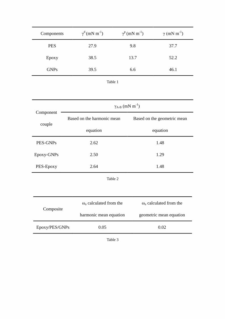
calculated using Equation (4) and are shown in Table 1). The interfacial tensions
Page 10
between each of the components were calculated according to Equation (2) and (3), and
are shown in Table 2. Finally, wetting coefficient data for the epoxy/PES blends filled
with GNPs were calculated according to Equation (1), and are shown in Table 3.
The value of wetting coefficient data lies between -1~1, hence it is predicted that
the GNPs will tend to be selectively located at the interface of the PES phase and the
epoxy phase.
3.2 Microstructure of the epoxy/PES blends
The morphologies of cured composites at various epoxy/PES weight ratios
(epoxy/PES = 10w/1w, 10w/2w, 10w/3w) were characterized using OM (Fig. 2). At 10
wt% of epoxy, the PES formed a large number of small domains (Fig. 2a); at 20 wt%, a
co-continuous phase structure was observed (Fig. 2b); and at 30 wt%, phase inversion
occurred (i.e., epoxy forms small phase domains throughout the PES matrix) (Fig. 2c).
Fig. 3 shows the phase inversion structure of the fractured surface of epoxy/PES
(epoxy/PES = 10w/3w). The phase components were analyzed using SEM and energy
dispersive spectrometry [72]. The results reveal that the network phase (area 2) contains
a greater amount of sulfur compared to the isolated spherical domain phase (area 1),
meaning that the network phase is the PES phase, and the isolated spherical domain
phase is the epoxy phase. Among the epoxy/PES compositions, epoxy/PES (epoxy/PES
= 10w/3w) was chosen as a suitable matrix composition, because a phase inversion
structure was expected to be a favorable template for distributing GNPs to form an
Page 11
effective network.
3.3 Microstructures of epoxy/PES/GNP composites
Fig. 4 shows the cross-section of the epoxy/PES/GNP and epoxy/GNP composites
with various filler content. In the epoxy/PES/GNPs composites (Fig. 4A~D), it can be
seen that PES formed a continuous phase in the blends and GNPs were observed in it. In
other words, the GNPs were selectively distributed at the interface of the blends or in
the PES phase. Additionally, the cross-section images demonstrate that GNPs gradually
contact with each other to form a filler pathway with increasing GNP content. When
GNP content increased to 10 wt%, the GNPs tended to connect together to construct a
filler network. However, a further increase in GNP content (15 wt%) led to significant
changes in the morphology of the composite, and only a few epoxy domains are clearly
observed in Fig. 4D. This occurs because when the GNP content reaches 15 wt%, the
difference in matrix viscosity increases rapidly and the compatibility of the matrix
changes, which in turn leads to an incomplete phase inversion structure, as shown in Fig.
4D and Fig. 5D. This means that a 3D interconnected template is not formed and thus a
3D interconnected filler network is not formed [52, 73]. For comparison, the
distribution of GNPs in the epoxy composites without PES is random, as shown in Fig.
4a~d.
Due to the reflective characteristic of GNPs, the distribution of GNPs can also be
Page 12
clearly observed by OM as shown in Fig. 5. In Fig. 5A and 5B, the arrows indicate the
locations of GNPs (GNPs are observed as white spots under xenon lamp irradiation),
the filler network structure has not yet been built. When the filler content reaches 10
wt%, the filler network is formed. These results are consistent with the SEM
observations.
Both SEM and OM images provide a powerful and direct proof of GNP network
formation throughout the entire matrix, but TEM is required to observe the detailed
location of GNPs.
The selective distribution of GNPs in the composites was visualized using TEM
(Fig. 6). The dark gray domain is the PES phase, whereas the light gray domain is the
epoxy phase. GNPs (shown by arrows) are located at the interface, and also in the PES
phase near the interface which may have resulted from a smaller interfacial tension
between the PES and GNPs. This observation is generally consistent with the prediction
based on wetting coefficient.
3.4 Thermal conductivity of epoxy/PES/GNPs composites
Fig. 7 shows the thermal conductivities of epoxy/GNPs and epoxy/PES/GNPs
(epoxy/PES = 10w/3w) composites with different GNPs content.
The thermal conductivity of epoxy/PES/GNPs composites and epoxy/GNPs
composites are relatively close when the GNPs content is small (1~7 wt%). However,
significant enhancement was observed in the thermal conductivity of epoxy/PES/GNPs
Page 13
composites as GNPs content increased to 10 wt% comparing with epoxy/GNPs
composites at the same filler loading. This demonstrates that 10 wt% GNPs content may
be a critical level for these epoxy composites. At small GNPs content, there are
insufficient GNPs to form a percolated, thermally conductive pathway. With further
increases in GNPs content, thermal conductivity in epoxy/PES/GNPs composites
increases remarkably. This is attributed to the formation of a three-dimensional filler
network via RIPS. Therefore, improved thermal conductivity of epoxy composites can
be achieved efficiently by the formation of filler network via RIPS, i.e. the thermal
transfer efficiency per unit mass of filler is increased by this strategy.
In order to demonstrate the thermal performance of epoxy/PES/10 wt% GNPs
composites, the surface temperature variations of the composites with time during
heating were recorded using an infrared thermograph. All the samples were placed on
a hot stage at 80 °C. The epoxy/PES/10 wt% GNPs composite has a much better
thermal response due to its higher thermal conductivity, and the surface temperature of
epoxy/PES/10 wt% GNPs composite continuously increases with time, at a higher rate,
as shown in Fig. 8. These results illustrate that epoxy/PES/10 wt% GNPs composite has
enhanced thermal conductivity.
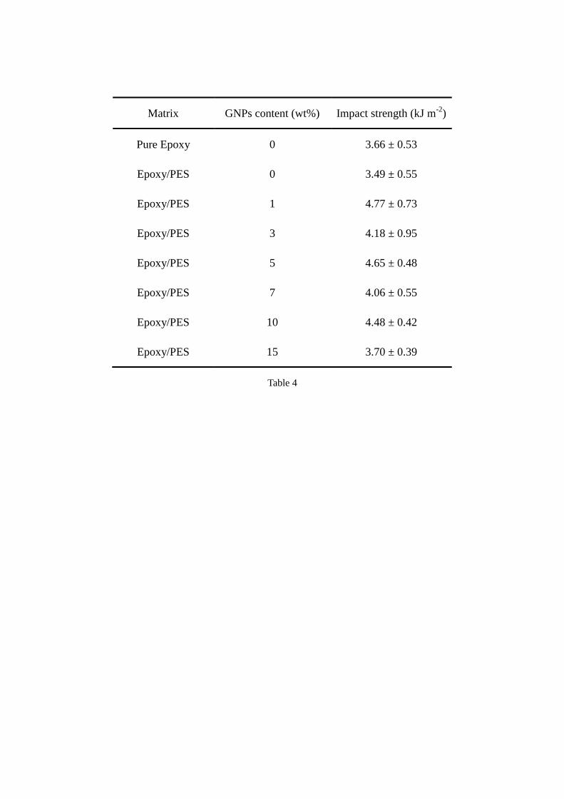
3.5 Impact strength of epoxy/PES/GNPs composites
The impact strength of epoxy/PES/GNPs composites is shown in Table 4. It can be
seen that the impact strength of pure epoxy and epoxy/PES without GNPs have little
Page 14
differences, but the impact strength of epoxy composites with 1~10 wt% GNPs
increases by 10~30% relative to pure epoxy. The GNPs which are located at the
interface and in PES phase near the interface, may have enhanced the binding force of
the interface and the toughness of the PES phase [74]. However, when the GNPs
content reaches 15 wt%, the impact strength decreases again. This may be due to
aggregates of GNPs acting as stress concentrators [25].
4. Conclusions
Using RIPS, an epoxy/PES blend can form a phase inverted structure. This phase
inverted structure functions as a template for GNPs to form a three-dimensional
connected network structure. The self-assembled structure of GNPs within the PES
phase leads to a composite with a high thermal conductivity at a relatively low GNPs
loading. This concept is illustrated in Fig. 9. Impact strength tests indicate that
mechanical properties of these composites are not compromised.
Acknowledgments
The authors are grateful for the support and funding from the Natural Science
Foundation of Jiangsu Province (BK20150956), National Natural Science Foundation
of China (No. 51703096), and the Priority Academic Program Development of Jiangsu
Higher Education Institutions (PAPD).
Page 15
Reference
[1] Zhi C, Bando Y, Tang C, Kuwahara H, Golberg D. Large-scale fabrication of boron
nitride nanosheets and their utilization in polymeric composites with improved thermal
and mechanical properties. Adv Mater 2009; 21(28): 2889-93.
[2] Moore A L, Shi L. Emerging challenges and materials for thermal management of
electronics. Mater Today 2014; 17(4): 163-74.
[3] Shan X, Liu Y, Wu Z, Liu H, Zhang Z, Huang R, et al. Preparation and property study
of graphene oxide reinforced epoxy resin insulation nanocomposites with high heat
conductivity. IOP Conference Ser Mater Sci Eng 2017; 171(1): 12151.
[4] Kholmanov I, Kim J, Ou E, Ruoff R S, Shi L. Continuous carbon nanotube–ultrathin
graphite hybrid foams for increased thermal conductivity and suppressed subcooling in
composite phase change materials. Acs Nano 2015; 9(12): 11699-707.
[5] Kuang Z, Chen Y, Lu Y, Liu L, Hu S, Wen S, et al. Fabrication of highly oriented
hexagonal boron nitride nanosheet/elastomer nanocomposites with high thermal
conductivity. Small 2015; 11(14): 1655-9.
[6] Ding P, Zhuang N, Cui X, Shi L, Song N, Tang S. Enhanced thermal conductive
property of polyamide composites by low mass fraction of covalently grafted graphene
nanoribbons. J Mater Chem C 2015; 3(42): 10990-7.
[7] Zhang W, Xu X, Yang J, Huang T, Zhang N, Wang Y, et al. High thermal conductivity
of poly(vinylidene fluoride)/carbon nanotubes nanocomposites achieved by adding
Page 16
polyvinylpyrrolidone. Compos Sci Technol 2015; 106: 1-8.
[8] Jiang Y, Liu Y, Min P, Sui G. BN@PPS core-shell structure particles and their 3D
segregated architecture composites with high thermal conductivities. Compos Sci
Technol 2017; 144: 63-9.
[9] Chen J, Huang X, Zhu Y, Jiang P. Cellulose nanofiber supported 3d interconnected bn
nanosheets for epoxy nanocomposites with ultrahigh thermal management capability.
Adv Funct Mater 2017; 27(5): 1604754.
[10] Wang X, Wu P. Preparation of highly thermally conductive polymer composite at
low filler content via a self-assembly process between polystyrene microspheres and
boron nitride nanosheets. Acs Appl Mater Inter 2017; 9(23): 19934-44.
[11] Li Y, Xu G, Guo Y, Ma T, Zhong X, Zhang Q, et al. Fabrication, proposed model and
simulation predictions on thermally conductive hybrid cyanate ester composites with
boron nitride fillers. Compos Part A - Appl Sci 2018; 107: 570-8.
[12] Wu K, Lei C, Huang R, Yang W, Chai S, Geng C, et al. Design and preparation of a
unique segregated double network with excellent thermal conductive property. Acs Appl
Mater Inter 2017; 9(8): 7637-47.
[13] Bai Q, Wei X, Yang J, Zhang N, Huang T, Wang Y, et al. Dispersion and network
formation of graphene platelets in polystyrene composites and the resultant conductive
properties. Compos Part A - Appl Sci 2017; 96: 89-98.
[14] Gu J, Lv Z, Wu Y, Zhao R, Tian L, Zhang Q. Enhanced thermal conductivity of
Page 17
SiCp/PS composites by electrospinning-hot press technique. Compos Part A - Appl Sci
2015; 79: 8-13.
[15] Gu J, Guo Y, Lv Z, Geng W, Zhang Q. Highly thermally conductive
POSS-g-SiCp/UHMWPE composites with excellent dielectric properties and thermal
stabilities. Compos Part A - Appl Sci 2015; 78: 95-101.
[16] Gu J, Zhang Q, Zhang J, Wang W. Studies on the preparation of polystyrene thermal
conductivity composites. Polym-Plast Technol 2010; 49(13): 1385-9.
[17] Jiang Y, Sun R, Zhang H, Min P, Yang D, Yu Z. Graphene-coated ZnO tetrapod
whiskers for thermally and electrically conductive epoxy composites. Compos Part A -
Appl Sci 2017; 94: 104-12.
[18] Gu J, Guo Y, Yang X, Liang C, Geng W, Tang L, et al. Synergistic improvement of
thermal conductivities of polyphenylene sulfide composites filled with boron nitride
hybrid fillers. Compos Part A - Appl Sci 2017; 95: 267-73.
[19] Hsiao M, Ma CM, Chiang J, Ho K, Chou T, Xie X, et al. Thermally conductive and
electrically insulating epoxy nanocomposites with thermally reduced graphene
oxide–silica hybrid nanosheets. Nanoscale 2013; 5(13): 5863.
[20] Wang J, Qiao J, Wang J, Zhu Y, Jiang L. Bioinspired hierarchical alumina–graphene
oxide–poly(vinyl alcohol) artificial nacre with optimized strength and toughness. Acs
Appl Mater Inter 2015; 7(17): 9281-6.
[21] Chen H, Ginzburg VV, Yang J, Yang Y, Liu W, Huang Y, et al. Thermal conductivity
Page 18
of polymer-based composites: Fundamentals and applications. Prog Polym Sci 2016; 59:
41-85.
[22] Lee J, Jung H, Yu S, Man Cho S, Tiwari VK, Babu Velusamy D, et al. Boron nitride
nanosheets (bnnss) chemically modified by “grafting-from” polymerization of
poly(caprolactone) for thermally conductive polymer composites. Chem-Asian J 2016;
11(13): 1921-8.
[23] Huang X, Wang S, Zhu M, Yang K, Jiang P, Bando Y, et al. Thermally conductive,
electrically insulating and melt-processable polystyrene/boron nitride nanocomposites
prepared by in situ reversible addition fragmentation chain transfer polymerization.
Nanotechnology 2015; 26(1): 15705.
[24] Yan W, Zhang Y, Sun H, Liu S, Chi Z, Chen X, et al. Polyimide nanocomposites with
boron nitride-coated multi-walled carbon nanotubes for enhanced thermal conductivity
and electrical insulation. J Mater Chem A 2014; 2(48): 20958-65.
[25] Yang X, Tang L, Guo Y, Liang C, Zhang Q, Kou K, et al. Improvement of thermal
conductivities for PPS dielectric nanocomposites via incorporating NH2-POSS
functionalized nBN fillers. Compos Part A - Appl Sci 2017; 101: 237-42.
[26] Shen X, Wang Z, Wu Y, Liu X, Kim J. Effect of functionalization on thermal
conductivities of graphene/epoxy composites. Carbon 2016; 108: 412-22.
[27] Ding P, Zhang J, Song N, Tang S, Liu Y, Shi L. Growing polystyrene chains from the
surface of graphene layers via RAFT polymerization and the influence on their thermal
Page 19
properties. Compos Part A - Appl Sci 2015; 69: 186-94.
[28] Wang F, Drzal LT, Qin Y, Huang Z. Mechanical properties and thermal conductivity
of graphene nanoplatelet/epoxy composites. J Mater Sci 2015; 50(3): 1082-93.
[29] Shen X, Wang Z, Wu Y, Liu X, He Y, Kim J. Multilayer graphene enables higher
efficiency in improving thermal conductivities of graphene/epoxy composites. Nano Lett
2016; 16(6): 3585-93.
[30] Hu Y, Shen J, Li N, Ma H, Shi M, Yan B, et al. Comparison of the thermal properties
between composites reinforced by raw and amino-functionalized carbon materials.
Compos Sci Technol 2010; 70(15): 2176-82.
[31] Yu A, Ramesh P, Sun X, Bekyarova E, Itkis ME, Haddon RC. Enhanced thermal
conductivity in a hybrid graphite nanoplatelet - carbon nanotube filler for epoxy
composites. Adv Mater 2008; 20(24): 4740-4.
[32] Huang J, Zhu Y, Xu L, Chen J, Jiang W, Nie X. Massive enhancement in the thermal
conductivity of polymer composites by trapping graphene at the interface of a polymer
blend. Compos Sci Technol 2016; 129: 160-5.
[33] Cao J, Zhao J, Zhao X, You F, Yu H, Hu G, et al. High thermal conductivity and high
electrical resistivity of poly(vinylidene fluoride)/polystyrene blends by controlling the
localization of hybrid fillers. Compos Sci Technol 2013; 89: 142-8.
[34] Gong J, Liu Z, Yu J, Dai D, Dai W, Du S, et al. Graphene woven fabric-reinforced
polyimide films with enhanced and anisotropic thermal conductivity. Compos Part A -
Page 20
Appl Sci 2016; 87: 290-6.
[35] Cui X, Ding P, Zhuang N, Shi L, Song N, Tang S. Thermal conductive and
mechanical properties of polymeric composites based on solution-exfoliated boron
nitride and graphene nanosheets: a morphology-promoted synergistic effect. Acs Appl
Mater Inter 2015; 7(34): 19068-75.
[36] Alam FE, Dai W, Yang M, Du S, Li X, Yu J, et al. In situ formation of a cellular
graphene frame work in thermoplastic composites leading to superior thermal
conductivity. J Mater Chem A 2017; 5(13): 6164-9.
[37] Cui C, Yan D, Pang H, Jia L, Bao Y, Jiang X, et al. Towards efficient electromagnetic
interference shielding performance for polyethylene composites by structuring
segregated carbon black/graphite networks. Chin J Polym Sci 2016; 34(12): 1490-9.
[38] Zhou H, Deng H, Zhang L, Fu Q. Significant enhancement of thermal conductivity
in polymer composite via constructing macroscopic segregated filler networks. Acs Appl
Mater Inter 2017; 9(34): 29071-81.
[39] Lian G, Tuan C, Li L, Jiao S, Wang Q, Moon K, et al. Vertically aligned and
interconnected graphene networks for high thermal conductivity of epoxy composites
with ultralow loading. Chem Mater 2016; 28(17): 6096-104.
[40] Li X, Shao L, Song N, Shi L, Ding P. Enhanced thermal-conductive and
anti-dripping properties of polyamide composites by 3D graphene structures at low filler
content. Compos Part A - Appl Sci 2016; 88: 305-14.
Page 21
[41] Yang J, Zhang E, Li X, Zhang Y, Qu J, Yu Z. Cellulose/graphene aerogel supported
phase change composites with high thermal conductivity and good shape stability for
thermal energy storage. Carbon 2016; 98: 50-7.
[42] Zeng X, Yao Y, Gong Z, Wang F, Sun R, Xu J, et al. Ice-templated assembly strategy
to construct 3d boron nitride nanosheet networks in polymer composites for thermal
conductivity improvement. Small 2015; 11(46): 6205-13.
[43] Shen H, Cai C, Guo J, Qian Z, Zhao N, Xu J. Fabrication of oriented hBN scaffolds
for thermal interface materials. Rsc Adv 2016; 6(20): 16489-94.
[44] Shao L, Shi L, Li X, Song N, Ding P. Synergistic effect of BN and graphene
nanosheets in 3D framework on the enhancement of thermal conductive properties of
polymeric composites. Compos Sci Technol 2016; 135: 83-91.
[45] Liu Z, Shen D, Yu J, Dai W, Li C, Du S, et al. Exceptionally high thermal and
electrical conductivity of three-dimensional graphene-foam-based polymer composites.
Rsc Adv 2016; 6(27): 22364-9.
[46] Chen L, Hou X, Song N, Shi L, Ding P. Cellulose/graphene bioplastic for thermal
management: Enhanced isotropic thermally conductive property by three-dimensional
interconnected graphene aerogel. Compos Part A - Appl Sci 2018; 107: 189-96.
[47] Yorifuji D, Ando S. Enhanced thermal conductivity over percolation threshold in
polyimide blend films containing ZnO nano-pyramidal particles: advantage of vertical
double percolation structure. J Mater Chem 2011; 21(12): 4402-7.
Page 22
[48] Cao J, Zhao X, Zhao J, Zha J, Hu G, Dang Z. Improved thermal conductivity and
flame retardancy in polystyrene/poly(vinylidene fluoride) blends by controlling selective
localization and surface modification of sic nanoparticles. Acs Appl Mater Inter 2013;
5(15): 6915-24.
[49] Ma CG, Xi DY, Liu M. Epoxy resin/polyetherimide/carbon black conductive
polymer composites with a double percolation structure by reaction-induced phase
separation. J Compos Mater 2013; 47(9): 1153-60.
[50] Chen J, Cui X, Zhu Y, Jiang W, Sui K. Design of superior conductive polymer
composite with precisely controlling carbon nanotubes at the interface of a co-continuous
polymer blend via a balance of π-π interactions and dipole-dipole interactions. Carbon
2017; 114: 441-8.
[51] Mao C, Zhu Y, Jiang W. Design of electrical conductive composites: tuning the
morphology to improve the electrical properties of graphene filled immiscible polymer
blends. Acs Appl Mater Inter 2012; 4(10): 5281-6.
[52] Huang J, Mao C, Zhu Y, Jiang W, Yang X. Control of carbon nanotubes at the
interface of a co-continuous immiscible polymer blend to fabricate conductive
composites with ultralow percolation thresholds. Carbon 2014; 73: 267-74.
[53] Chen J, Du X, Zhang W, Yang J, Zhang N, Huang T, et al. Synergistic effect of
carbon nanotubes and carbon black on electrical conductivity of PA6/ABS blend.
Compos Sci Technol 2013; 81:1-8.
Page 23
[54] Chen J, Shi Y, Yang J, Zhang N, Huang T, Chen C, et al. A simple strategy to achieve
very low percolation threshold via the selective distribution of carbon nanotubes at the
interface of polymer blends. J Mater Chem 2012; 22(42): 22244-398.
[55] Deng H, Lin L, Ji M, Zhang S, Yang M, Fu Q. Progress on the morphological control
of conductive network in conductive polymer composites and the use as electroactive
multifunctional materials. Prog Polym Sci 2014; 39(4): 627-55.
[56] Zhang Y, Shi W, Chen F, Han C C. Dynamically asymmetric phase separation and
morphological structure formation in the epoxy/polysulfone blends. Macromolecules
2011; 44(18): 7465-72.
[57] Zhang Y, Chen F, Liu W, Zhao S, Liu X, Dong X, et al. Rheological behavior of the
epoxy/thermoplastic blends during the reaction induced phase separation. Polymer 2014;
55(19): 4983-9.
[58] Wang M, Yu Y, Li S. Polymerization-induced phase separation in polyethersulfone
modified epoxy resin systems: effect of curing reaction mechanism. Sci China Ser B
2007; 50(4): 554-61.
[59] Yu Y, Wang M, Gan W, Tao Q, Li S. Polymerization-induced viscoelastic phase
separation in polyethersulfone-modified epoxy systems. J Phys Chem B 2004; 108(20):
6208-15.
[60] Liu C, Ma F, Zhang Z, Yang J, Wang Y, Zhou Z. Selective localization of organic
montmorillonite in poly(L-lactide)/poly(ethylene vinyl acetate) blends and the resultant
Page 24
properties. Compos Part B - Eng 2017; 123: 1-9.
[61] Abbasian A, Ghaffarian SR, Mohammadi N, Fallahi D. The contact angle of
thin-uncured epoxy films: thickness effect. Coll Surf A 2004; 236(1-3): 133-40.
[62] Wu D, Lin D, Zhang J, Zhou W, Zhang M, Zhang Y, et al. Selective localization of
nanofillers: effect on morphology and crystallization of pla/pcl blends. Macromol Chem
Phys 2011; 212(6): 613-26.
[63] Zhu D, Li X, Wang N, Wang X, Gao J, Li H. Dispersion behavior and thermal
conductivity characteristics of Al2O3–H2O nanofluids. Curr Appl Phys 2009; 9(1): 131-9.
[64] Gustavsson M, Karawacki E, Gustafsson SE. Thermal conductivity, thermal
diffusivity, and specific heat of thin samples from transient measurements with hot disk
sensors. Rev Sci Instrum 1994; 65(12): 3856-9.
[65] Goldel A, Marmur A, Kasaliwal GR, Potschke P, Heinrich G. Shape-dependent
localization of carbon nanotubes and carbon black in an immiscible polymer blend during
melt mixing. Macromolecules 2011; 44(15): 6094-102.
[66] Li Y, Wang S, Zhang Y, Zhang Y. Carbon black-filled immiscible
polypropylene/epoxy blends. J Appl Polym Sci 2006; 99(2): 461-71.
[67] Wu G, Asai S, Sumita M, Yui H. Entropy penalty-induced self-assembly in carbon
black or carbon fiber filled polymer blends. Macromolecules 2002; 35(3): 945-51.
[68] Gubbels F, Jerome R, Vanlathem E, Deltour R, Blacher S, Brouers F. Kinetic and
thermodynamic control of the selective localization of carbon black at the interface of
Page 25
immiscible polymer blends. Chem Mater 1998; 10(5): 1227-35.
[69] Sumita M, Sakata K, Asai S, Miyasaka K, Nakagawa H. Dispersion of fillers and the
electrical-conductivity of polymer blends filled with carbon-black. Polym Bull 1991;
25(2): 265-71.
[70] Wu S. Polymer interface and adhesion. New York: M. Dekker;1982.
[71] Owens DK, Wendt RC. Estimation of the surface free energy of polymers. J Appl
Polym Sci 1969; 13(8): 1741-7.
[72] Kishi H, Tanaka S, Nakashima Y, Saruwatari T. Self-assembled three-dimensional
structure of epoxy/polyethersulphone/silver adhesives with electrical conductivity.
Polymer 2016; 82: 93-9.
[73] Liu Y, Zhong X, Zhan G, Yu Y, Jin J. Effect of mesoscopic fillers on the
polymerization induced viscoelastic phase separation at near- and off-critical
compositions. J Phys Chem B 2012; 116(12): 3671-82.
[74] Gu J, Zhang Q, Li H, Tang Y, Kong J, Dang J. Study on preparation of SiO2/epoxy
resin hybrid materials by means of sol-gel. Polym-Plast Technol 2007; 46(12): 1129-34.
Page 26
Figures caption:
Fig. 1 Schematic showing the preparation of epoxy/PES/GNPs composites.
Fig. 2 OM images of epoxy/PES composites with various weight ratios: (a) 10w/1w; (b) 10w/2w; (c)
10w/3w.
Fig. 3 SEM micrographs of phase inversion structure. The elemental content of areas in the micrographs
was analyzed by energy dispersive spectrometer.
Fig. 4 SEM images of epoxy/PES/GNPs and epoxy/GNPs composites at different GNP contents.
Epoxy/PES/GNPs: (A) 3 wt% GNPs; (B) 7 wt% GNPs ; (C) 10 wt% GNPs; (D) 15 wt% GNPs;
epoxy/GNPs: (a) 3 wt% GNPs; (b) 7 wt% GNPs ; (c) 10 wt% GNPs; (d) 15 wt% GNPs.
Fig. 5 OM images of epoxy/PES/GNPs and epoxy/GNPs composites at different GNPs contents.
Epoxy/PES/GNPs: (A) 3 wt% GNPs; (B) 7 wt% GNPs ; (C) 10 wt% GNPs; (D) 15 wt% GNPs;
epoxy/GNPs: (a) 3 wt% GNPs; (b) 7 wt% GNPs ; (c) 10 wt% GNPs; (d) 15 wt% GNPs.
Fig. 6 TEM images of the GNP distribution in (a) the epoxy/PES/1 wt% GNPs composite and (b) the
epoxy/PES/7 wt% GNPs composite.
Fig. 7 Thermal conductivities of epoxy/PES/GNPs and epoxy/GNPs composites as a function of GNP
content.
Fig. 8 (a) IR images of () pure epoxy, () epoxy/10 wt% GNPs and () epoxy/PES/10 wt% GNPs with
heating time; (b) surface temperature variation of samples with heating time
Fig. 9 Structure evolution of thermally conductive epoxy/PES/GNPs composites with RIPS
Table 1 The surface energy data of components.
Table 2 Interfacial tensions γA-B between different components calculated using the harmonic and
geometric mean equations.
Page 27
Table 3 Wetting coefficient as calculated using the harmonic and geometric mean equation.
Table 4 The impact strength of pure epoxy and epoxy composites
Fig. 1
Fig. 2
Page 28
Fig. 3
Fig. 4
Fig. 5
Fig. 6
Page 29
Fig. 7
Fig. 8
Fig. 9
Page 30
Components γd
(mN m-1
) γp
(mN m-1
) γ (mN m-1
)
PES 27.9 9.8 37.7
Epoxy 38.5 13.7 52.2
GNPs 39.5 6.6 46.1
Table 1
Component
couple
γA-B (mN m-1
)
Based on the harmonic mean
equation
Based on the geometric mean
equation
PES-GNPs 2.62 1.48
Epoxy-GNPs 2.50 1.29
PES-Epoxy 2.64 1.48
Table 2
Composite
ωa calculated from the
harmonic mean equation
ωa calculated from the
geometric mean equation
Epoxy/PES/GNPs 0.05 0.02
Table 3
Page 31
Matrix GNPs content (wt%) Impact strength (kJ m-2
)
Pure Epoxy 0 3.66 ± 0.53
Epoxy/PES 0 3.49 ± 0.55
Epoxy/PES 1 4.77 ± 0.73
Epoxy/PES 3 4.18 ± 0.95
Epoxy/PES 5 4.65 ± 0.48
Epoxy/PES 7 4.06 ± 0.55
Epoxy/PES 10 4.48 ± 0.42
Epoxy/PES 15 3.70 ± 0.39
Table 4


![Constructing a filler network for thermal conductivity ... › files › 12496715 › ... · the design of electrically conductive composites [52-55]. For example, it has been found](https://static.documents.pub/doc/80x56/5f0417517e708231d40c467a/constructing-a-filler-network-for-thermal-conductivity-a-files-a-12496715.jpg)


