Constructing Journal Week 10 Tutorial: Site Visit - Oval Pavilion The pipe above is an exposed aggie drain. It has slits in it so that water can seap inside, the drain is put at the base of any retaining wall so that the water gets drained away. The wood is used as bearers or strongbacks in the building. They are LVL as if you look at it it is made out of lots of veneers Above is the right side of the pavilion and it is one stage behind the other side. That is; the concrete has not yet been poured. Here we can see the formwork which later bcomes ‘lost’ in the con- crete. For this side, the builders forgot to drill into the concrete block wall first to connect the stairs to it with steel bars, so it had to be done later The holes seen in the image above are for reinforce- ment, the reinforcement gets placed into it once the stairs get put in. This makes it so there is a con- nection to the existing structure This wall (Left) has a pattern on it of wood. This is because when the formwork is put up, they then put the oregon on and when it is poured it leaves the impression of the wood on the concrete. Doing the walls like this takes longer and is more ex- pensive than a simple plain wall. The slot on the end of the timber - as seen to the right is an interesting detail. On the end of the steel member there is a plate which is welded on and fixed to the wood. This helps support the roof structure.
Transcript
Constructing Journal Week 10Tutorial: Site Visit - Oval Pavilion
The pipe above is an exposed aggie drain. It has slits in it so that water can seap inside, the drain is put at the base of any retaining wall so that the water gets drained away. The wood is used as bearers or strongbacks in the building. They are LVL as if you look at it it is made out of lots of veneers
Above is the right side of the pavilion and it is one stage behind the other side. That is; the concrete has not yet been poured. Here we can see the formwork which later bcomes ‘lost’ in the con-crete. For this side, the builders forgot to drill into the concrete block wall first to connect the stairs to it with steel bars, so it had to be done later
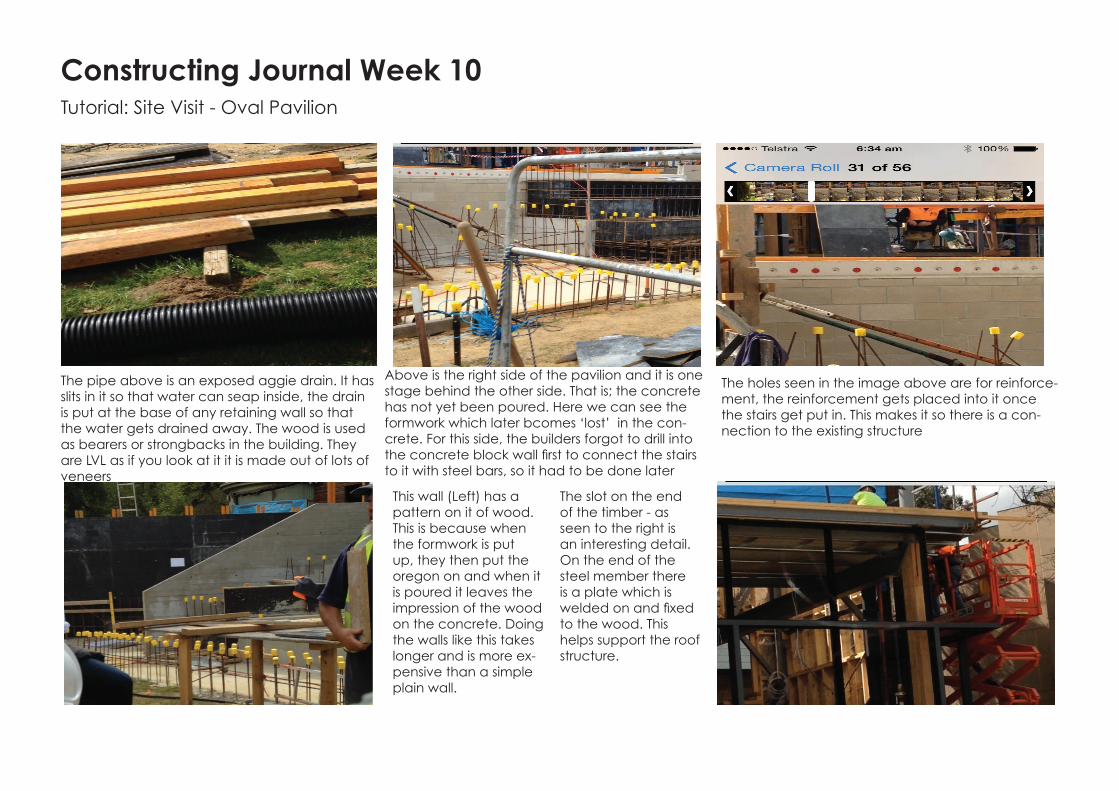
The holes seen in the image above are for reinforce-ment, the reinforcement gets placed into it once the stairs get put in. This makes it so there is a con-nection to the existing structure
This wall (Left) has a pattern on it of wood. This is because when the formwork is put up, they then put the oregon on and when it is poured it leaves the impression of the wood on the concrete. Doing the walls like this takes longer and is more ex-pensive than a simple plain wall.
The slot on the end of the timber - as seen to the right is an interesting detail. On the end of the steel member there is a plate which is welded on and fixed to the wood. This helps support the roof structure.
BLUE is the retaining wall, it is currently not set in place, however the reinforcing steel bars can be seen, along with the bright yellow bar caps for safety. There were meant to be two walls initially - the retaining wall and the first wall for the seating and it was supposed to be filled with soil between, but it got too muddy, so there is only one wall. There is a spoon drain with collects the water from the oval, and this connects to the aggie drain which flows out to the stormwater drain. PINK is where timber wood is going to run along in the direction of the lines - this is for aesthetic purposes along the endge of the seating as this ‘step’ is the first level of seating. In these stands there is ‘lost’ formwork, which is when you form it but then leave the formwork in there because there is no way to cut it out.
Z Purlins with 25mm blue-tongue flooring sitting on top
Rod bracers, these can be adjusted unlike fixed braces which cannot be adjusted as they are welded in place. The rod brace only works in tension , like a cable
Glossary Word and Reading
Deflection is how much a particular structural element is displaced. For example the bending of beams with a heavy load on top. The image to the right also shows deflection as the vertical balsa wood (when pressure is applied) is buckling. The amount of deflection is decided by how much the wood has changed. The BLACK line indicates the position the wood was initially at, and the BLUE shows how much the wood has deflected out to the side.
I have learnt all this from past readings as in one they talked about deflection. I have found recently that every-thing is coming together because of the readings - now I can understand much more.