journal homepage: www.elsevier.com/locate/nanoenergy Available online at www.sciencedirect.com RAPID COMMUNICATION Constructing optimized wire electrodes for fiber supercapacitors Bin Liu a,b , Boyang Liu b , Xianfu Wang b , Di Chen b , Zhiyong Fan c,n , Guozhen Shen a,n a State Key Laboratory for Superlattices and Microstructures, Institute of Semiconductors, Chinese Academy of Sciences, Beijing 100083, PR China b Wuhan National Laboratory for Optoelectronics (WNLO) and College of Optical and Electronic Information, Huazhong University of Science and Technology, Wuhan 430074, PR China c Department of Electronic and Computer Engineering, Hong Kong University of Science and Technology, Clear Water Bay, Kowloon, Hong Kong, PR China Received 5 June 2014; received in revised form 10 August 2014; accepted 28 August 2014 Available online 8 September 2014 KEYWORDS Fiber supercapacitor; Optimized; Wire electrode; Mn 2 O 3 cubes; Flexible Abstract Fiber electronic devices are commonly built on fibrous substrates with the advantages for the direct use as weavable and embedded device units or integrated textile modules. In this work, Mn 2 O 3 cube-arrays/carbon wire electrodes were designed for a new kind of fiber super- capacitors. To realize micro-devices with well-optimized performance, different electrode structures were designed and fabricated including the straight, bent, and coiled fiber super- capacitors (S-FSC, B-FSC, and C-FSC), among which the C-FSC showed the optimized and best performance. Our work confirmed that the performance of micro-devices can be well tuned by simply tailoring the device architectures. & 2014 Elsevier Ltd. All rights reserved. Introduction As integration, miniaturization, flexibility, and optimization are considered as the primary features of the new generation of electronics, enormous effort has been paid on developing flexible and wearable devices in recent years [1–12]. Different from conventional two-dimensional planar electronics, fiber electronic devices are commonly built on one-dimensional fibrous/wire substrates. Fiber electronic devices usually show advantages for the direct use as wearable and embedded device units or integrated textile modules that cannot be fulfilled by conventional planar devices, which are very attractive in realizing miniaturized portable devices and http://dx.doi.org/10.1016/j.nanoen.2014.08.021 2211-2855/& 2014 Elsevier Ltd. All rights reserved. n Corresponding authors. E-mail addresses: [email protected](D. Chen), [email protected](Z. Fan), [email protected](G. Shen). Nano Energy (2014) 10, 99–107
Bin Liua,b, Boyang Liub, Xianfu Wangb, Di Chenb,Zhiyong Fanc,n, Guozhen Shena,n
aState Key Laboratory for Superlattices and Microstructures, Institute of Semiconductors, ChineseAcademy of Sciences, Beijing 100083, PR ChinabWuhan National Laboratory for Optoelectronics (WNLO) and College of Optical and ElectronicInformation, Huazhong University of Science and Technology, Wuhan 430074, PR ChinacDepartment of Electronic and Computer Engineering, Hong Kong University of Science and Technology,Clear Water Bay, Kowloon, Hong Kong, PR China
Received 5 June 2014; received in revised form 10 August 2014; accepted 28 August 2014Available online 8 September 2014
AbstractFiber electronic devices are commonly built on fibrous substrates with the advantages for thedirect use as weavable and embedded device units or integrated textile modules. In this work,Mn2O3 cube-arrays/carbon wire electrodes were designed for a new kind of fiber super-capacitors. To realize micro-devices with well-optimized performance, different electrodestructures were designed and fabricated including the straight, bent, and coiled fiber super-capacitors (S-FSC, B-FSC, and C-FSC), among which the C-FSC showed the optimized and bestperformance. Our work confirmed that the performance of micro-devices can be well tuned bysimply tailoring the device architectures.& 2014 Elsevier Ltd. All rights reserved.
Introduction
As integration, miniaturization, flexibility, and optimizationare considered as the primary features of the new generation
014.08.021hts reserved.
t.edu.cn (D. Chen),ac.cn (G. Shen).
of electronics, enormous effort has been paid on developingflexible and wearable devices in recent years [1–12]. Differentfrom conventional two-dimensional planar electronics, fiberelectronic devices are commonly built on one-dimensionalfibrous/wire substrates. Fiber electronic devices usually showadvantages for the direct use as wearable and embeddeddevice units or integrated textile modules that cannot befulfilled by conventional planar devices, which are veryattractive in realizing miniaturized portable devices and
multi-functional “smart textiles” for sensors, detectors, dis-plays and implanted medical devices. Several kinds of fiberelectronic devices have been designed including fiber logiccircuits [13], fiber solar cells [14,15], fiber displays [16], andfiber nanogenerators [17], etc.
The development of fiber electronic devices inspired muchinterest in developing efficient, lightweight, highly flexible/wearable energy storage devices such as fiber solar cells,fiber lithium ion batteries, and fiber supercapacitors (FSC)since they are one of the key components for fully flexibleelectronic systems. Among the emerged fiber energy devices,fiber supercapacitors have higher power density, longercycling life and more safe operation than fiber lithium ionbatteries and thus are considered as a new class of energystorage components. Since Wang's group reported the firstprototype of FSC made from ZnO nanowires [18], FSCs madeof different electrodes were designed. For examples, Penget al. designed FSC by twisting two aligned MWCNT fibers[19]. Miao et al. fabricated yarn FSCs based on CNT@PANIarrays [20]. To better prevent the twisted fiber-electrodesfrom electric short during bending, Zou et al. demonstratedthe well-designed helical spacer wire placed in between twoelectrodes [21]. Our group also fabricated FSCs made ofZnCo2O4 nanowires electrode and grapheme electrode [22].
Although different kinds of FSCs with different performanceswere successfully designed recently, one key and crucial issuethat was neglected is how to improve the performance of eachFSC. As is known, Mn2O3 has many unique advantages in energystorage fields, such as low cost, environmentally friendly, andhigh potential performance, etc. Although many methods havebeen developed to synthesize various Mn2O3 electrodes forsupercapacitors under different experimental conditions, suchas particles, nanorods, and spheres [23–25], no informationabout Mn2O3 cube/carbon fiber-electrodes prepared via a low-cost/facile route was disclosed till now. Herein, with Mn2O3
cube arrays/carbon fibers as electrodes, we demonstrated thatthe performance of the designed FSCs can be efficientlyimproved by simply varying the electrode structure (straight,bent, and coiled fiber electrodes, respectively). Both experi-ments and theoretical simulations were carried out to demon-strate the efficient strategy to get optimized FSCs.
Experimental section
Synthesis of Mn2O3 cube-arrays/carbon fibersmatrix
Mn(AC)2 (2 mmol) and urea (2 mmol) was initially dissolved indistilled water (40 mL) and then the solution was transferredinto a Teflon-lined autoclave. Pre-cleaned carbon fibers werethen immersed in this solution. A typical hydrothermal reac-tion at 160 1C for 5 h was then performed, which resulted inthe formation of the aligned Mn2O3 cube arrays grown on thecarbon fibers. The morphology and microstructure of thesamples were investigated by field emission scanning elec-tron microscopy (FE-SEM; Sirion 200).
Wire-device fabrication and characterization
After placing two as-synthesized composite fibers as work-ing electrodes on a PET film, the silver electrodes were
fixed to the two ends of the PET substrate. A gel electrolyteof PVA/H2SO4 was transferred on the composite fibers toform a thin all-solid-state device. CV characteristics of thefiber supercapacitors were evaluated by sweeping thevoltage from 0 to 0.8 V at various scan rates using a CHIelectrochemical station (760D). Galvanostatic charge–dis-charge curves of these devices were measured at differentcurrent densities between 0 and 0.8 V using a PVA/H2SO4 gelelectrolyte with the electrochemical station at the roomtemperature.
Computational simulations
The simulations of the capacitors were carried out by usingANSYS Maxwell. To calculate the capacity, the width of eachelectrode was set as 1 mm, and the length of the capacitors,the distance between two electrodes were set as 50 mm and2 mm, respectively. In addition, the voltages on the twofiber electrodes are symmetrically set as +0.4 V and�0.4 V.
Results and discussion
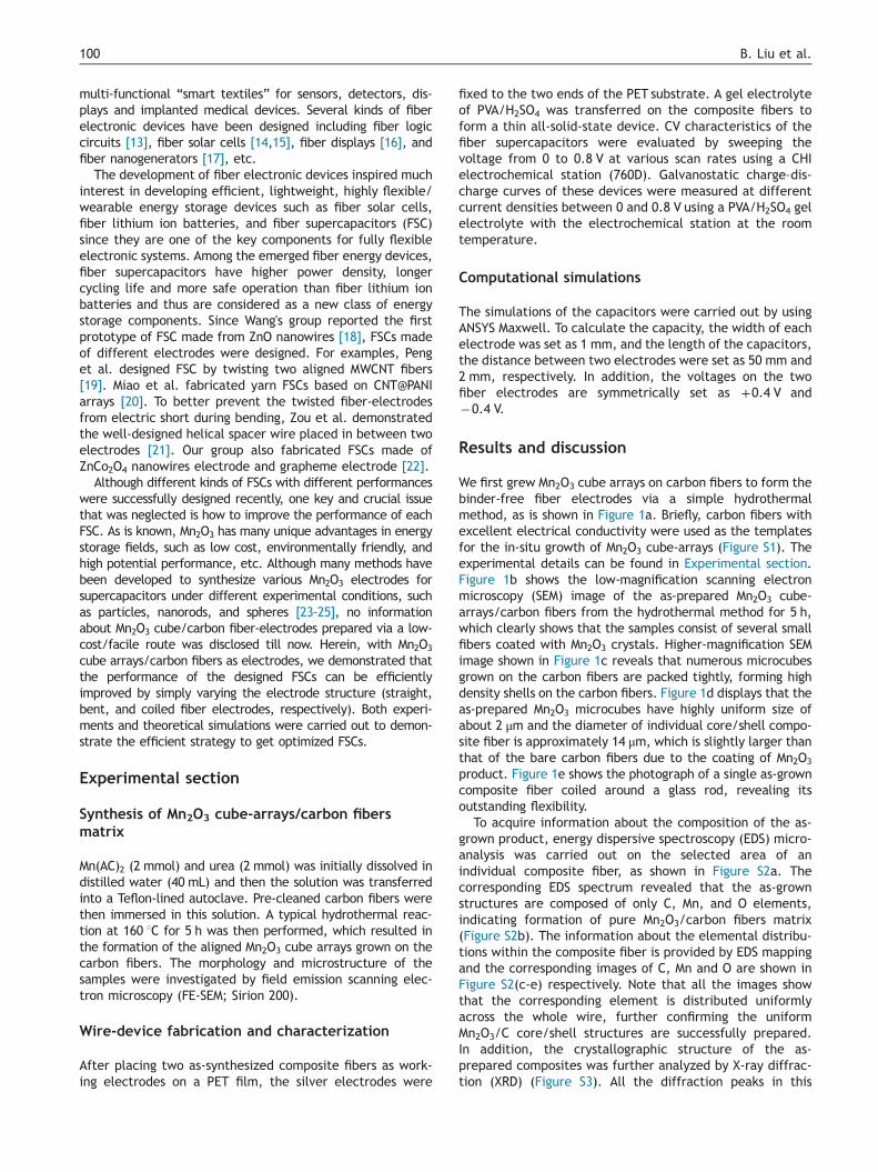
We first grew Mn2O3 cube arrays on carbon fibers to form thebinder-free fiber electrodes via a simple hydrothermalmethod, as is shown in Figure 1a. Briefly, carbon fibers withexcellent electrical conductivity were used as the templatesfor the in-situ growth of Mn2O3 cube-arrays (Figure S1). Theexperimental details can be found in Experimental section.Figure 1b shows the low-magnification scanning electronmicroscopy (SEM) image of the as-prepared Mn2O3 cube-arrays/carbon fibers from the hydrothermal method for 5 h,which clearly shows that the samples consist of several smallfibers coated with Mn2O3 crystals. Higher-magnification SEMimage shown in Figure 1c reveals that numerous microcubesgrown on the carbon fibers are packed tightly, forming highdensity shells on the carbon fibers. Figure 1d displays that theas-prepared Mn2O3 microcubes have highly uniform size ofabout 2 μm and the diameter of individual core/shell compo-site fiber is approximately 14 μm, which is slightly larger thanthat of the bare carbon fibers due to the coating of Mn2O3
product. Figure 1e shows the photograph of a single as-growncomposite fiber coiled around a glass rod, revealing itsoutstanding flexibility.
To acquire information about the composition of the as-grown product, energy dispersive spectroscopy (EDS) micro-analysis was carried out on the selected area of anindividual composite fiber, as shown in Figure S2a. Thecorresponding EDS spectrum revealed that the as-grownstructures are composed of only C, Mn, and O elements,indicating formation of pure Mn2O3/carbon fibers matrix(Figure S2b). The information about the elemental distribu-tions within the composite fiber is provided by EDS mappingand the corresponding images of C, Mn and O are shown inFigure S2(c-e) respectively. Note that all the images showthat the corresponding element is distributed uniformlyacross the whole wire, further confirming the uniformMn2O3/C core/shell structures are successfully prepared.In addition, the crystallographic structure of the as-prepared composites was further analyzed by X-ray diffrac-tion (XRD) (Figure S3). All the diffraction peaks in this
Figure 1 Sample fabrication and morphology characterization. (a) Schematic of the material synthesis via a facile hydrothermalapproach. (b–d) SEM images of the Mn2O3 cube-arrays/carbon fibers composites. (e) Photographs of the looped (upper photo) and thecoiled (lower photo, around the glass rod) as-grown composite fibers.
101Constructing optimized wire electrodes
pattern can be readily indexed as cubic-phase Mn2O3, whichare consistent with the values in the standard card (JCPDSCard no. 41-1442) [26]. Meanwhile, the peaks at around 261and 431 can be attributed to the carbon templates.
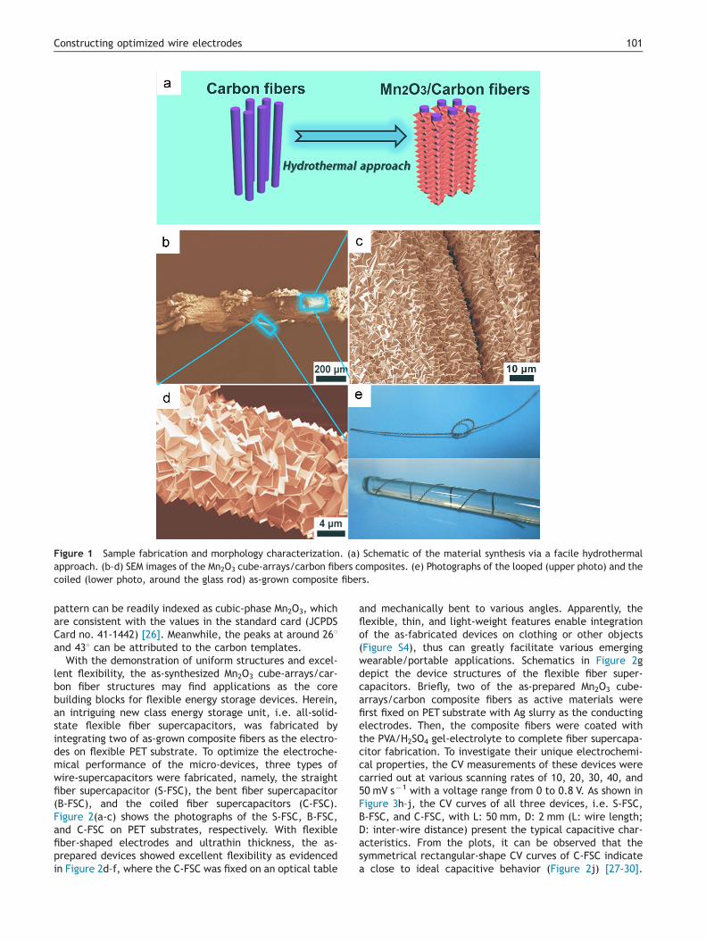
With the demonstration of uniform structures and excel-lent flexibility, the as-synthesized Mn2O3 cube-arrays/car-bon fiber structures may find applications as the corebuilding blocks for flexible energy storage devices. Herein,an intriguing new class energy storage unit, i.e. all-solid-state flexible fiber supercapacitors, was fabricated byintegrating two of as-grown composite fibers as the electro-des on flexible PET substrate. To optimize the electroche-mical performance of the micro-devices, three types ofwire-supercapacitors were fabricated, namely, the straightfiber supercapacitor (S-FSC), the bent fiber supercapacitor(B-FSC), and the coiled fiber supercapacitors (C-FSC).Figure 2(a-c) shows the photographs of the S-FSC, B-FSC,and C-FSC on PET substrates, respectively. With flexiblefiber-shaped electrodes and ultrathin thickness, the as-prepared devices showed excellent flexibility as evidencedin Figure 2d–f, where the C-FSC was fixed on an optical table
and mechanically bent to various angles. Apparently, theflexible, thin, and light-weight features enable integrationof the as-fabricated devices on clothing or other objects(Figure S4), thus can greatly facilitate various emergingwearable/portable applications. Schematics in Figure 2gdepict the device structures of the flexible fiber super-capacitors. Briefly, two of the as-prepared Mn2O3 cube-arrays/carbon composite fibers as active materials werefirst fixed on PET substrate with Ag slurry as the conductingelectrodes. Then, the composite fibers were coated withthe PVA/H2SO4 gel-electrolyte to complete fiber supercapa-citor fabrication. To investigate their unique electrochemi-cal properties, the CV measurements of these devices werecarried out at various scanning rates of 10, 20, 30, 40, and50 mV s�1 with a voltage range from 0 to 0.8 V. As shown inFigure 3h–j, the CV curves of all three devices, i.e. S-FSC,B-FSC, and C-FSC, with L: 50 mm, D: 2 mm (L: wire length;D: inter-wire distance) present the typical capacitive char-acteristics. From the plots, it can be observed that thesymmetrical rectangular-shape CV curves of C-FSC indicatea close to ideal capacitive behavior (Figure 2j) [27–30].
Figure 2 Fiber-device demonstration and electrochemical characteristics of the as-fabricated fiber-supercapacitors measured atvarious scan rates between 0 and 0.8 V. Photographs of (a, b and c) three as-fabricated fiber-devices: S-FSC, B-FSC, and C-FSCrespectively, and (d–f) bending process of a C-FSC device. (g) Schematics of different architectures of three devices, showing severalcomponents of these micro-supercapacitors. Cyclic voltammetry of these devices based on Mn2O3 cube-arrays/carbon fibers electrodesmeasured between 0 and 0.8 V at various scan rates. Three mini-type fiber-supercapacitors: (h) S-FSC, (i) B-FSC, and (j) C-FSC.
B. Liu et al.102
It reveals the composite electrodes in this work are mainlydescribed as a double-layer behavior that includes physicalcharge-adsorption on the surface of active-materials not
chemical reactions on electrodes during charge–dischargeprocess. This common phenomenon is observed in manysymmetric supercapacitors reported previously [22,30–32].
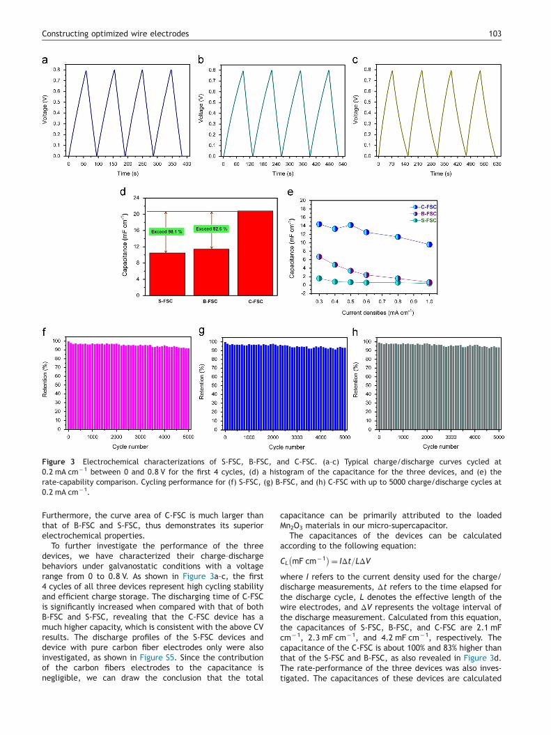
Figure 3 Electrochemical characterizations of S-FSC, B-FSC, and C-FSC. (a–c) Typical charge/discharge curves cycled at0.2 mA cm�1 between 0 and 0.8 V for the first 4 cycles, (d) a histogram of the capacitance for the three devices, and (e) therate-capability comparison. Cycling performance for (f) S-FSC, (g) B-FSC, and (h) C-FSC with up to 5000 charge/discharge cycles at0.2 mA cm�1.
103Constructing optimized wire electrodes
Furthermore, the curve area of C-FSC is much larger thanthat of B-FSC and S-FSC, thus demonstrates its superiorelectrochemical properties.
To further investigate the performance of the threedevices, we have characterized their charge–dischargebehaviors under galvanostatic conditions with a voltagerange from 0 to 0.8 V. As shown in Figure 3a–c, the first4 cycles of all three devices represent high cycling stabilityand efficient charge storage. The discharging time of C-FSCis significantly increased when compared with that of bothB-FSC and S-FSC, revealing that the C-FSC device has amuch higher capacity, which is consistent with the above CVresults. The discharge profiles of the S-FSC devices anddevice with pure carbon fiber electrodes only were alsoinvestigated, as shown in Figure S5. Since the contributionof the carbon fibers electrodes to the capacitance isnegligible, we can draw the conclusion that the total
capacitance can be primarily attributed to the loadedMn2O3 materials in our micro-supercapacitor.
The capacitances of the devices can be calculatedaccording to the following equation:
CL mF cm�1� �¼ IΔt=LΔV
where I refers to the current density used for the charge/discharge measurements, Δt refers to the time elapsed forthe discharge cycle, L denotes the effective length of thewire electrodes, and ΔV represents the voltage interval ofthe discharge measurement. Calculated from this equation,the capacitances of S-FSC, B-FSC, and C-FSC are 2.1 mFcm�1, 2.3 mF cm�1, and 4.2 mF cm�1, respectively. Thecapacitance of the C-FSC is about 100% and 83% higher thanthat of the S-FSC and B-FSC, as also revealed in Figure 3d.The rate-performance of the three devices was also inves-tigated. The capacitances of these devices are calculated
B. Liu et al.104
from each discharge curves at various current densities of0.3, 0.4, 0.5, 0.6, 0.8, and 1.0 mA cm�1, respectively. Thecorresponding results are summarized in Figure 3e. Clearly,the C-FSC shows the best rate performance among all threedevices.
Since the cycling performance is a crucial parameter for atypical capacitor, it is important to study the retention ofcapacitances cycled over numerous times. Figure 3f, g and hdemonstrate the cycling performance of the S-FSC, B-FSC,and C-FSC for as many as 5000 charge/discharge cycles at0.2 mA cm�1, the results show that the retention of S-FSC,B-FSC, and C-FSC can maintain as high as 91%, 93%, and 94%after 5000 charge/discharge cycles, respectively, indicatingthe excellent cycling stability of all the three devices.Therefore, all the above results indicate that our fabricatedunique fiber supercapacitors possess superior performance,which is crucial for high-performance electronics.
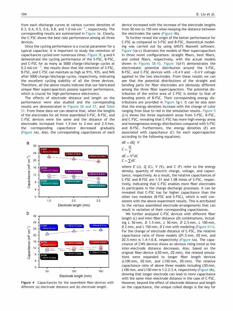
The effects of electrode distance and length on theperformance were also studied and the correspondingresults are demonstrated in Figures S6 and S7, and TableS1. From these data we can observe that, when the lengthsof the electrodes for all three assembled S-FSC, B-FSC, andC-FSC devices were the same and the distance of theelectrodes increased from 1.5 mm to 2 mm and 2.5 mm,the corresponding capacitance decreased gradually(Figure 4a). Also, the corresponding capacitances of each
Figure 4 Capacitances for the assembled fiber-devices withdifferent (a) electrode distance and (b) electrode length.
device increased with the increase of the electrode lengthsfrom 50 mm to 150 mm when keeping the distance betweenthe electrodes the same (Figure 4b).
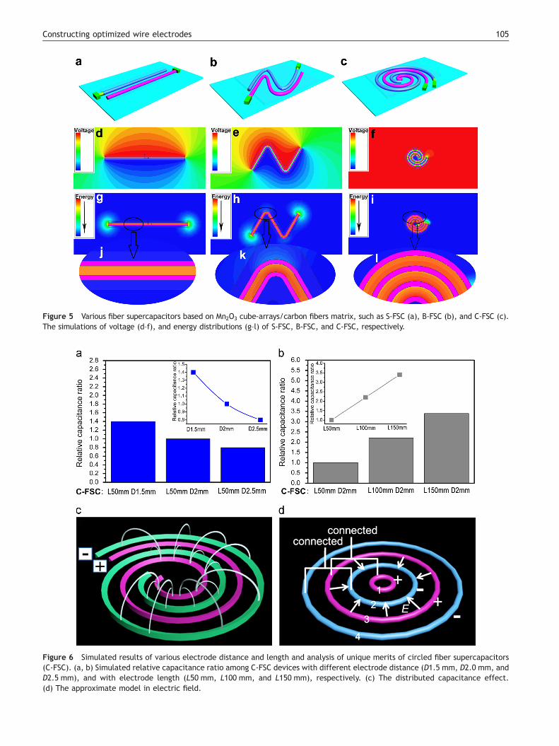
To further reveal the origin of the better performance forC-FSC as compared to S-FSC and B-FSC, theoretical model-ing was carried out by using ANSYS Maxwell software.Figure 5(a-c) illustrates the models of fiber supercapacitorsin three novel configurations: straight fibers, bent fibers,and coiled fibers, respectively, with the actual modelsshown in Figures S8-10. Figure 5(d-f) demonstrates theelectrostatic potential distribution around the S-FSC,B-FSC, and C-FSC devices with +0.4 V and �0.4 V voltageapplied to the two electrodes. From these results we cansee that the potential distributions of the straight andbending parts for fiber electrodes are obviously differentamong the three fiber supercapacitors. The potential dis-tribution of the entire area of C-FSC is similar to that ofbending points of B-FSC. Their corresponding energy dis-tributions are provided in Figure 5g–i. It can be also seenthat the energy densities increase with the change of colorranging from blue to red in the simulation results. Figure 5(j-l) shows the three equivalent areas from S-FSC, B-FSC,and C-FSC, revealing that C-FSC has more high-energy areasand homogeneous energy-distributions compared with S-FSCand B-FSC. Furthermore, the energy densities (E) areassociated with capacitance (C) for each supercapacitoraccording to the following equations:
dE ¼ dQ UV
C¼ QV
dE ¼ V2dCC¼∑dC
where E (J), Q (C), V (V), and C (F) refer to the energydensity, quantity of electric charge, voltage, and capaci-tance, respectively. As a result, the relative capacitances ofC-FSC and B-FSC are 1.51 and 1.08 times of S-FSC, respec-tively, indicating that C-FSC enables more fiber electrodesto participate in the charge–discharge processes. It can berevealed that C-FSC has far higher capacitance than theother two modules (B-FSC and S-FSC), which is well con-sistent with the above experiment results. This is attributedto the various assembled electrode-arrangements that canresult in variation of their corresponding capacitances.
We further analyzed C-FSC devices with different fiberlength (L) and inter-fiber distance (D) combinations, includ-ing L 50 mm, D 1.5 mm, L 50 mm, D 2.5 mm, L 100 mm,D 2 mm, and L 150 mm, D 2 mm with modeling (Figure S11).For the change of electrode distance of C-FSC, the relativecapacitance ratio of three models (D1.5 mm, D2 mm, andD2.5 mm) is 1.4:1:0.8, respectively (Figure 6a). The capa-citance of CWS devices shows an obvious rising trend as theinter-electrode distance decreases. Also, based on theoriginal fiber-device (L50 mm, D2 mm), the related simula-tions were expanded to longer fiber length devices(L100 mm, D2 mm, and L150 mm, D2 mm). The relativecapacitance ratio of above three models including L50 mm,L100 mm, and L150 mm is 1:2.2:3.4, respectively (Figure 6b),showing that longer electrode can lead to more capacitancewith the same inter-electrode distance in the case of C-FSC.However, beyond the effect of electrode distance and lengthon the capacitance, the unique coiled design is the key for
Figure 5 Various fiber supercapacitors based on Mn2O3 cube-arrays/carbon fibers matrix, such as S-FSC (a), B-FSC (b), and C-FSC (c).The simulations of voltage (d–f), and energy distributions (g–l) of S-FSC, B-FSC, and C-FSC, respectively.
Figure 6 Simulated results of various electrode distance and length and analysis of unique merits of circled fiber supercapacitors(C-FSC). (a, b) Simulated relative capacitance ratio among C-FSC devices with different electrode distance (D1.5 mm, D2.0 mm, andD2.5 mm), and with electrode length (L50 mm, L100 mm, and L150 mm), respectively. (c) The distributed capacitance effect.(d) The approximate model in electric field.
105Constructing optimized wire electrodes
B. Liu et al.106
the high capacitance and energy storage capacity. From theabove results, we have discovered that, by designing deviceswith different configurations, we can easily tune the capa-citance and rate performances of the devices though allthe three devices use similar electrodes with the sameamount of active materials. Since the three types of micro-supercapacitors have electrodes with the same length anddistance, one may draw the conclusion that they should havethe same capacitance. However, increased capacitance wasobserved for the C-FSC devices in our experiments. Weattribute this fact to the synergetic effects of the coiledfiber electrode configuration for the C-FSC device, which canbe explained as follows. For the C-FSC, its compact designcan lead to close to ideal space-utilization and the max-imized total capacitance, due to the coupling among thenon-adjacent fiber electrodes with the opposite polarity, asshown in Figure 6c. Compared with S-FSC, B-FSC, and C-FSCinvolves more portions of fiber electrodes to participate incharge–discharge processes, which results in well-optimizedperformance of C-FSC in terms of capacitance and ratestability. To further explain higher capacity of C-FSC ascompared to S-FSC and B-FSC, a simplified model of C-FSCwas built, as shown in Figure 6d. For a single round ringcapacitor with one pair of inner and outer fiber electrodes,typically only the electric field between the two electrodesneed to be considered. And, the weak electric field outsidethe rings can be ignored. In Figure 6d, if the electric fieldbetween the ring electrode 2 and 3 is ignored temporarily,the C-FSC can be regarded as a parallel connected two singleround ring capacitors. S-FSC can also be treated as twoseparated straight line capacitors, as shown in Figure S12.Here, both S-FSC and C-FSC have same average length andthese simplified approximate models were demonstrated tobetter make some qualitative analysis of fiber-devices. Formthe plot, it can be seen that the total capacitance of a C-FSCis the same with that of a S-FSC. According to the Gauss Law:IS-E Ud-S ¼ 1
εq
where E refers to the electric field intensity on an arbitraryclosed surface S, ε refers to the permittivity, and q refers tothe total electric charge surrounded by the closed surface.For the devices with two electrodes with the same length anddistance, the capacitances of a straight line and a ringcapacitor should be same. However, once the electric fieldbetween ring electrodes 2 and 3 is considered, the integral ofthe electric field intensity through the Gaussian surface willbe increased, and the negative electric charge on ringelectrode 2 will be increased as well, so is the positivecharge on ring electrode 3. While the electric field distribu-tion in between ring electrodes 1 and 2, 3 and 4 does notchange, leading to the unaltered electric charge on ringelectrodes 1 and 4. These naturally results in higher capaci-tance and more charge stored of a C-FSC device, ascompared to a S-FSC and a B-FSC, due to their simple andnon-optimized structures. Hence, all these results indicatethat novel C-FSC presented here can achieve desired well-optimized properties.
In addition, the fundamental formula that determines thecapacitance of a capacitor is illustrated as follows: C=(εS)/4πkd, where C is the capacitance of the capacitor, ε is thedielectric constant of the material between the electrodes,
S is the surface area of one electrode, k is electrostaticconstant, and d is the distance between two electrodes.Considering the definite thickness of the three-dimensionalelectrodes, the wire-shaped supercapacitors can also beapproximatively analyzed as parallel combinations of plate-capacitors. Here, for the effect of electrostatic equilibrium,the electron charges are only distributed on the insidesurface of the electrodes of S-FSC and B-FSC. But for theC-FSC, the electron charges are distributed on the bothinside and outside surface of its electrodes (except for theinnermost/outmost ring). As a result, for the same lengthand distance of electrodes, the effective surface area (S) ofC-FSC is much larger than the other two devices, thusrevealing that optimized C-FSC can achieve the highestcapacitance among these devices.
Conclusions
In summary, here we report a novel flexible Mn2O3 cube-arrays/carbon fiber structure that has been fabricated intostraight, bent, and coiled fiber supercapacitors on flexiblePET substrates. These flexible devices based on micro-fibersdemonstrated desirable capacitive behaviors, excellentcycling life-time, and high rate-capacity. Among all threetypes of devices, the C-FSC delivered the highest capaci-tance and best rate-capability as compared with the S-FSCand B-FSC, due to its unique compact configuration. Ourresults also revealed that the inter-electrode distance andlength can affect the performance of the devices. Overall,the fiber supercapacitors demonstrated here may satisfythe increasing demands on reliable power sources for next-generation electronics which requires flexibility and portability.
Acknowledgments
This work was supported by the National Natural ScienceFoundation of China (91123008, 61377033) and the 973Program of China (2011CB933300).
Appendix A. Supporting information
Supplementary data associated with this article can befound in the online version at http://dx.doi.org/10.1016/j.nanoen.2014.08.021.
References
[1] D. Khang, H. Jiang, Y. Huang, J.A. Rogers, Science 311 (2006) 208.[2] Z. Jiang, W. Xie, M. Li, B. Podobnik, W. Zhou, H. Stanley, Proc.
Natl. Acad. Sci. USA 110 (2013) 1600.[3] Y. Cui, C.M. Lieber, Science 291 (2001) 851.[4] Y. Cui, Z. Zhong, D. Wang, W. Wang, C.M. Lieber, Nano Lett. 3
(2003) 149.[5] S. Xu, Y. Zhang, J. Cho, J. Lee, X. Huang, L. Jia, J. Fan, Y. Su,
J. Su, H. Zhang, H. Cheng, B. Lu, C. Yu, C. Chuang, T. Kim,T. Song, K. Shigeta, S. Kang, C. Dagdeviren, I. Petrov, P.V. Braun, Y. Huang, U. Paik, J.A. Rogers, Nat. Commun. 4(2013) 1543.
[6] B. Liu, J. Zhang, X. Wang, G. Chen, D. Chen, C. Zhou, G. Shen,Nano Lett. 12 (2012) 3005.
[7] B. Liu, X. Wang, H. Chen, Z. Wang, D. Chen, Y. Cheng, C. Zhou,G. Shen, Sci. Rep. 3 (2013) 1622.
[8] J. Chmiola, C. Largeot, P. Taberna, P. Simon, Y. Gogotsi,Science 328 (2010) 480.
[9] C. Yue, Y. Yu, J. Yin, T. Wong, Y. Zang, J. Li, J. Kang, J. Mater.Chem. A 1 (2013) 7896.
[10] L. Hu, H. Wu, F. Mantia, Y. Yang, Y. Cui, ACS Nano 4 (2010)5843.
[11] L. Hu, M. Pasta, F. Mantia, L. Cui, S. Jeong, H. Deshazer,J. Choi, S. Han, Y. Cui, Nano Lett. 10 (2010) 708.
[12] X. Cai, M. Peng, X. Yu, Y.P. Fu, D.C. Zou, J. Mater. Chem. C 2(2014) 1184.
[13] M. Hamedi, R. Forchheimer, O. Inganas, Nat. Mater. 6 (2007)357.
[14] X. Fan, Z.Z. Chu, F.Z. Wang, C. Zhang, L. Chen, Y.W. Tang,D.C. Zou, Adv. Mater. 20 (2008) 592.
[15] D.C. Zou, D. Wang, Z.Z. Chu, Z.B. Lv, X. Fan, Coord. Chem.Rev. 254 (2010) 1169.
[16] B.O. Connor, K.H. An, Y. Zhao, K.P. Pipe, M. Shtein, Adv. Mater.19 (2007) 3897.
[17] Y. Qin, X.D. Wang, Z.L. Wang, Nature 451 (2008) 809.[18] J. Bae, M. Song, Y. Park, J. Kim, M.L. Liu, Z.L. Wang, Angew.
Chem. Int. Ed. 50 (2011) 1683.[19] J. Ren, L. Li, C. Chen, X. Chen, Z. Cai, L. Qiu, Y. Wang, X. Zhu,
H. Peng, Adv. Mater. 25 (2013) 1155.[20] K. Wang, Q. Meng, Y. Zhang, Z. Wei, M. Miao, Adv. Mater. 25
(2013) 1494.[21] Y. Fu, X. Cai, H. Wu, Z. Lv, S. Hou, M. Peng, X. Yu, D. Zou, Adv.
Mater. 24 (2012) 5713.[22] B. Liu, D. Tan, X. Wang, D. Chen, G. Shen, Small 9 (2013) 1998.[23] X.Y. Wang, L. Liu, X.Y. Wang, L.H. Yi, C.Y. Hu, X.Y. Zhang,
Mater. Sci. Eng. B 176 (2011) 1232.[24] K.W. Park, J. Mater. Chem. A 2 (2014) 4292.[25] S.L. Chen, F. Liu, Q.J. Xiang, X.H. Feng, G.H. Qiu, Electrochim.
Acta 106 (2013) 360.[26] J. Wang, G. Zhu, L. Deng, L. Kang, Z. Hao, Z. Liu, CrystEng-
Comm 14 (2012) 8253.[27] X.Y. Lang, A. Hirata, T. Fujita, M. Chen, Nat. Nanotechnol. 6
(2011) 232.[28] Y. He, W. Chen, X. Li, Z. Zhang, J. Fu, C. Zhao, E. Xie, ACS
Nano 7 (2013) 174.[29] L. Yang, S. Cheng, Y. Ding, X. Zhu, Z.L. Wang, M.L. Liu, Nano
Lett. 12 (2011) 321.[30] Q. Wang, X. Wang, B. Liu, G. Yu, X. Hou, D. Chen, G. Shen,
J. Mater. Chem. A 1 (2013) 2468.[31] X. Lu, X. Huang, S. Xie, T. Zhai, C. Wang, P. Zhang, M. Yu,
W. Li, C. Liang, Y. Tong, J. Mater. Chem. 22 (2012) 13357.[32] Y. Horng, Y. Lu, Y. Hsu, C. Chen, L. Chen, K. Chen, J. Power
Sources 195 (2010) 4418.
Bin Liu is a Postdoctoral Researcher at PacificNorthwest National Laboratory (PNNL). Hereceived his Ph.D. degree from HuazhongUniversity of Science and Technology (HUST)in 2014. His research interest covers new-generation energy storage devices based oncreative electrodes, such as flexible/wearableLi-ion batteries, fiber supercapacitors, alter-native Mg-ion batteries, etc.
Boyang Liu is currently a Ph.D. candidateat University of Maryland, College Park. Hereceived his B.E. degree from Huazhong Uni-versity of Science and Technology in 2014. Hisresearch focuses on synthesis and design offlexible energy storage devices and theirsimulations.
Xianfu Wang received his Bachelor’s degreefrom Jiangsu University in 2010. He is currenta Ph.D. candidate at Huazhong University ofScience and Technology. His current researchfocuses on the design and synthesis of threedimensional nanostructures, and investigationof their fundamental properties and potentialapplications in flexible energy storage devicesand integrated devices.
Di Chen received her B.S. degree (1999) inChemistry from Anhui Normal University andPh.D. degree (2005) in Chemistry from theUniversity of Science and Technology of China.She is currently a Professor at the HuazhongUniversity of Science and Technology. Herresearch interests focus on designing nanos-tructures for sustainable energy applications,including energy storage, solar cell, andphotocatalysts.
Zhiyong Fan received his B.S. and M.S. degreein physical electronics from Fudan University,Shanghai, China, in 1998 and 2001. Hereceived Ph.D. degree from University ofCalifornia, Irvine in 2006 in Materials Science.In May 2010, he joined Hong Kong Universityof Science and Technology as an assistantprofessor. His current research includes fabri-cation and characterization of nanomaterialsand nanostructures; applications of functional
nanomaterials for electronics, energy harvest-ing and sensing.
Guozhen Shen received his B.S. degree (1999)in Chemistry from Anhui Normal University andPh.D. degree (2003) in Chemistry from Uni-versity of Science and technology of China. Hejoined the Institute of Semiconductors, Chi-nese Academy of Sciences as a Professor in2013. His current research focused on flexibleelectronics and printable electronics, includingtransistors, photodetectors, sensors and flex-ible energy storage and conversion devices.