Page 1
S O M A L I A
Report 12
2040
020
400
2040
020
400
2015
020
020
400
20
2040
020
200
1,21
020
020
400
20
20 240 20 240 20 400 20 150 200 20 400 20 600
420 420 420 620
1,24
0
3 ROOMHEALTH POST
3 ROOMMODULARHEALTHFACILITY
4 ROOMMCH /
HEALTH CENTRE
2.0m wide covered verandahceramic tiles
Room 01ceramic tiles
Room 02ceramic tiles
Room 03ceramic tiles
2.0m
wid
e co
vere
d ve
rand
ahce
ram
ic ti
les
Room 01ceramic tiles
Room 03ceramic tiles
Room 02ceramic tiles
Room 04ceramic tiles
2.0m wide covered verandahceramic tiles
Room 01ceramic tiles
Room 03ceramic tiles
Room 02ceramic tiles
open to skycourtyard
open to skypaved walkwayprecast concrete pavings
open to skycourtyard
open to skycourtyard
CONSTRUCTIONGUIDELINES FORHEALTH FACILITIES
Page 2
2
Authors: Austen Davis
Moyiz Ebrahimjee (Architect)
Ali El-Amine (Engineer)
Joseph Aduda (Architectural Assistant)
This document was written by and produced with the financial assistance of the European Union. The views
expressed herein can in no way be taken to reflect the official opinion of the European Union.
Page 3
3
Acronyms ..................................................................................................................................................... 4
cHAPTEr 1: InTroducTIon ...................................................................................................5
cHAPTEr 2: THE modulAr HEAlTH cEnTrE ........................................................................7 2.1 Health Centre: Floor Plan ................................................................................................................... 7
2.2 Health Centre: Elevation .................................................................................................................... 8
cHAPTEr 3: THE PrImAry HEAlTH unIT (PHu) or HEAlTH PosT ........................................9 3.1 The PHU: Floor Plan ........................................................................................................................... 9
3.2 The PHU: Elevation ............................................................................................................................ 10
cHAPTEr 4: THE HEAlTH cEnTrE - oPd ................................................................................11 4.1 The OPD Block: Floor Plan ................................................................................................................. 11
4.2 The OPD Block: Elevation .................................................................................................................. 12
4.3 The Maternity: Floor Plan ................................................................................................................... 13
4.4 The Maternity: Elevation. ................................................................................................................... 14
cHAPTEr 5: THE HEAlTH cEnTrE – IPd .................................................................................15 5.1 The IPD: Floor Plan ............................................................................................................................ 15
5.2 The IPD: Elevation ............................................................................................................................. 16
cHAPTEr 6: sHowEr Block ..................................................................................................17 6.1 Shower Block: Floor Plan ................................................................................................................... 17
6.2 Shower Block: Elevation .................................................................................................................... 18
cHAPTEr 7: ToIlET Block .....................................................................................................19 7.1 Toilet Block: Floor Plan ....................................................................................................................... 19
7.2 Toilet Block: Elevation ........................................................................................................................ 20
7.3 Latrine (Pit) Block: Floor Plan ............................................................................................................. 20
7.4 Latrine (Pit) Block: Elevation .............................................................................................................. 21
cHAPTEr 8: wAsTE dIsPosAl ...............................................................................................22 8.1 Incinerator: Floor Plan ........................................................................................................................ 22
8.2 Incinerator: Elevation ......................................................................................................................... 23
Annex (diskette) Bill of Quantities and detailed drawings
Contents
Page 4
4
ANC Ante Natal Care
BoQ Bill of Quantities
EPHS Essential Package of Health Services
HC Health Centre
HP Health Post
IPD In-Patient Department
JNA Joint Needs Assessment
MCH Maternal and Child Health Clinic
MoH Ministry of Health
NEZ North East Zone
NGO Non Governmental Organization
NWZ North West Zone
OPD Out-Patient Department
PHU Primary Health Unit
RHC Referral Health Centre
SCZ South Central Zone
UN United Nations
UNICEF United Nations Children’s Fund
UNOPs United Nations Organization for Project Services
Acronyms
Page 5
5
The Somali health sector has been characterized
as under-funded, fragmented and ineffective.
Government, UN, NGO and community providers
struggle to provide services with limited and
unpredictable inputs and a lack of centralized and
strategically directed financing or direction/policy.
In the South Central zone, NGOs and local community
organizations typically run health facilities broadly in line
with three tiers of service provision. In the 2 Northern
zones government is also a main provider of primary
health care services.
Health posts (HPs) are the lowest tier of service
provider: They typically consist of one or two semi-
trained staff without formal salaries or supervision –
operating out of a 1 -2 room facility or a local house or
shop (no formal facility).
Maternal and Child Health Centers (MCHs) are
the inter-mediate tier of service provider: they are
highly variable. They have from 1 – 12 staff some
with professional nurses and midwives, others with
no professional higher than an auxiliary (especially in
rural areas). The range and quality of services varies
enormously with some MCHs seeing 3,000 patients a
month and others seeing less than 50!
Hospitals are the highest tier of service provision: they
are also highly variable with 10 – hundreds of staff –
and most with a medical doctor and some professional
nurses or midwives. However, even hospitals lack
professional staff and especially the diversity of
technical staff necessary to run a full hospital service.
With the extreme diversity of facilities and the variability
in range of services – extent of support and type of
support offered (UN agency, NGO, government) it is no
wonder there is little uniformity in the quality and range
of services offered between facilities and within a tier
of service level.
Recognizing the extremely dilapidated state of much
of the Somali health infrastructure, The Joint Needs
Assessment (JNA) for Somalia determined the need
for the development of standardized blueprints for
health facilities as an important technical task to allow
a move towards the standardization of services offered
within a particular tier of service delivery. Standard
building guidelines also offer the potential for costing
construction and infrastructure elements of health
system development and therefore are an important
component of planning for a future health system.
In a workshop in 2007, representatives from the health
sector came together and agreed to try and establish
operating norms and standards for what levels of care
each tier should follow. The UNICEF health systems
strengthening programme developed a process of
extensive consultation and review and eventually
produced an Essential Package of Health Services
(EPHS).
Introduction1
Page 6
6
The EPHS defines the range of services (and therefore
supplies and staff competencies) necessary to offer at
each tier level. Projecting from the range of services
and staff required, it is possible to define the level of
facility needed to house each tier of service provision.
This also means we can develop standard blueprints
for health facilities at each level. The EPHS defines a
standard:
The “new” names of EPHS facilities have been
changed to disconnect levels of service provision from
political administrative boundaries/unit names (districts/
regions) so that facilities can be planned for according
to need and not political calculus. And to highlight
the need for real change as in each case, significant
changes in focus are prescribed for each tier of service.
This cannot be created piecemeal and is essential
to start generating real performance and returns on
investment I the health sector.
This report presents concepts for standard health
facility design at each tier of service. The design
concept is modular. In consultation with health
authorities we agreed a basic PHU/HP. The PHU
building is used as part of the MCH/Health Centre and
this HC facility is used as part of a referral centre etc.
so that any building can be upgraded to a higher tier of
service and to keep overall construction costs and the
types of buildings required as simple (and cheap) as
possible.
All buildings have been designed to use simple but high
quality building techniques with simple roof structures
and external corridors etc.
While all designs are simple – relatively cheap and
locally appropriate, it is not expected that all facilities
will follow specifications to the letter. All facility
blueprints need to be adapted to the site and conditions
of the site at hand – rural MCHs may have to be
constructed on relatively small sites. Rural facilities
will need to take into consideration soils, water supply,
drainage and ventilation. However basic designs,
floor layout plans and indicative Bills of Quantities are
developed for each structure and these BoQs can be
modified to allow adaptation to the local site and needs.
Furthermore, innovations are encouraged (for example
in areas where there is more regular rainfall throughout
the year, constructors may wish to include submerged
tanks to collect roof run-off). Lastly these plans can
be developed over time as experience grows with
construction and planning.
This report presents basic floor plans and elevations –
however there are a large range of detailed drawings
to guide constructors that should be printed out on A3.
In addition there are BoQs that can easily be adapted
to promote professional construction in any setting
adapted to the local constructions challenges (soil
type, drainage, water availability, ventilation, coastal/in-
land). The detailed booklets for each building type are
available on diskette or through the health coordination
bodies and at MoH offices.
Previous Tiers of Service Standardized EPHS Tiers of Service
Health Post (HP) Primary Health Unit (PHU)
Maternal and Child Health Centre (MCH) Health centre (HC)
District Hospital Referral Health Centre
Regional Hospital Hospital
Referral Hospital
Page 7
7
The modular Health Centre is depicted in the 2 drawings that follow
PINK = HEALTH POST/PRIMARY HEALTH UNIT
PINK + GREEN = BASIC OPD
PINK + GREEN + BLUE = OPD + maternity services
PINK + GREEN + BLUE + YELLOW = FULL HC OPD/IPD
2.1 Health Centre: Floor Plan
240
240
240
2040
020
400
2040
020
400
2015
020
020
400
20
2040
020
200
1,21
020
020
400
20
620 420
620
280
200
480
600 20 200 20 180 20
20 240 20 240 20 400 20 150 200 20 400 20 600 20 600 20
420 420 420 620
310 310
410
400
410
320
1,24
0
3 ROOMHEALTH POST
TOILET BLOCK
SHOWERBLOCK
3 ROOMMODULARHEALTHFACILITY
4 ROOMMCH /
HEALTH CENTRE
REFERAL HEALTHCENTRE
2.0m wide covered verandahceramic tiles
Proposed sketch layout for afull scale MCH master planwith 8 bed Inpatient ward
Room 01ceramic tiles
Room 02ceramic tiles
Room 03ceramic tiles
2.0m
wid
e co
vere
d ve
rand
ahce
ram
ic ti
les
Room 01ceramic tiles
Room 03ceramic tiles
Room 02ceramic tiles
Room 04ceramic tiles
2.0m wide covered verandahceramic tiles
Room 01ceramic tiles
Room 03ceramic tiles
Room 02ceramic tiles
open to skycourtyard
staff roomceramic ti les
staff roomceramic ti les
8bed inpatient wardceramic tiles
open to skypaved walkwayprecast concrete pavings
shw
rsh
wr
cesspool
septictank
ladiesceramic tiles
gentsceramic tiles
open to sky walkwayprecast concrete pavings
open to skycourtyard
FURTUREDEVELOPMENT
gentsceramic tiles
whb
whb
ladiesceramic tiles
WC
WC
WC
WC
dhobisinks
open to skycourtyard
TheModularHealthCentre2
Page 8
8
2.2 Health Centre: Elevation3 ROOM
HEALTH POST
SHOWERBLOCK
TOILETBLOCK
FUTUREDEVELOPMENT
SHOWERBLOCK
TOILETBLOCK
3 ROOMHEALTH POST
FUTUREDEVELOPMENT
3 ROOMMODULAR HEALTH
FACILITY
3 ROOMMODULAR HEALTH
FACILITY
4 ROOMMCH / HEALTH CENTRE
4 ROOMMCH / HEALTH CENTRE
REFERAL HEALTHCENTRE
REFERAL HEALTHCENTRE
Perspective Viewfrom front Courtyard
Perspective Viewfrom rear side
Page 9
9
ThePrimaryHealthUnit(PHU)orHealthPost3
3.1 The PHU: Floor Plan
200
420
260 260 420
260 260 420
200
420
2018
020
400
20
2018
044
0
2018
020
400
20
640
2018
014
515
014
5
2018
014
515
014
5
640
125
150
125
100
9021
0
130 90 60 90 170 90 80 150 60
20 240 20 240 20 400 20
960
20 240 20 240 20 400 20
960
20 240 20 240 20 400 20
90 100 130 100 245 150 145
70 100 70 40 100 40 60 125 150 125
+0.15
+0.30+0.30
0.00
A
A 02
01
03 04
100mm diaPVC RWP
100mm diaPVC RWP
60x60x5cmprecast concretepaving slabslaid to falls
100mm diaPVC RWP
100mm diaPVC RWP
1
2
3
1
2
3
A B C D
A B C D
ConsultationRoom
ceramic tiles
Storeceramic tiles
Covered verandahceramic tiles
beam above beam above beam above
beam
abo
ve
beam
abo
ve
step up step up step up
step
up
step
up
ConsultationRoom
ceramic tiles
5cm
thic
k co
nc s
helv
es
Ground Floor Plan scale 1:100
Indicative Construction Cost (see BoQs): 14,500 USD
The PHU is the lowest tier of service provision. The
building is produced as a single block with a simple
A-frame roof and covered external passage. The block
has 3 rooms which can be used inter-changeably. One
room is designed to serve as a store and will have
no windows (most likely the middle room with less
external walls for lighting.
This building is to be incorporated into a full health
Centre and will then serve as one wing of the U-shaped
compound. The building is envisaged to have the
central room as main stores and the end room (left)
as another temporary store with dispensing window
to serve as a dispensary. The end room to the right
would be the lab and is well lit with maximum number
of windows.
PINK = HEALTH POST/PRIMARY
HEALTH UNIT
Page 10
3.2
The
PHU:
Ele
vatio
n
60x6
0x5
cm p
reca
stco
nc. p
avin
g s
labs
laid
to fa
lls
GI c
orru
gate
d ro
ofin
g s
heet
s15
o de
gre
es r
oof
pitc
h
Pe
rsp
ecti
ve V
iew
10
Page 11
11
TheHealthCentre-OPD4Indicative Construction Cost (see BoQs): 22,000 USD
In upgrading a PHU to an MCH – OPD it is envisaged there is a need to add 2 blocks
GREEN – Main Consultation Block
BLUE – Maternal and Reproductive Health Block
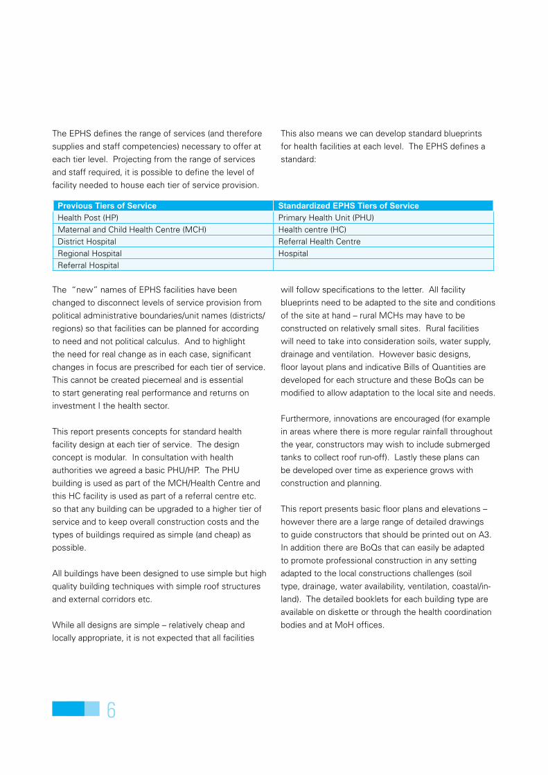
4.1 The OPD Block: Floor PlanThe OPD block has 4 standard rooms and a covered external passage. All rooms are designed to be used for
consultation. The PHU building is now converted for use as a laboratory and medical store with dispensary.
200 420
200 420
420
420
420
420
420
420
420
420
20 180 20 400 20
640
20 180 145 150 145
20 180 20 400 20
640
20 180 145 150 145
2040
020
400
2040
020
400
20
1,70
0
2040
020
400
2040
020
400
20
2040
020
400
2040
020
400
20
145
150
270
150
270
150
270
150
145
1,70
0
180 20 125 150 125
180 20 125 150 125
400
6015
080
9020
2090
8015
060
6015
080
9020
2090
8015
060
200 420
3030
098
9013
080
47
200 420
3030
098
9013
080
47
+0.30
0.00
+0.30
+0.30
+0.30+0.15
+0.15
01
A A
02
03
04
60x60x5cmprecast concretepaving slabslaid to falls
100mm diaPVC RWP
line of roof overhangabove
100mm diaPVC RWP
0.00(ground level)
+0.30(ground floor level)
hw timber fascia boardpainted
+3.30(ring beam level)
GI corrugated roofingsheets 15o degreesroof pitch
textured paint finish toexternal plastered walls
sliding aluminiumwindow to schedule
30X30cm box frame withsteel wire mesh for
ventilation of the roof
0.00(ground level)
+0.30(ground floor level)
hw timber fascia boardpainted
+3.30(ring beam level)
GI corrugated roofingsheets 15o degreesroof pitch
textured paint finish toexternal plastered walls
sliding aluminiumwindow to schedule
30X30cm box frame withsteel wire mesh for
ventilation of the roof
Room 01ceramic tiles
Room 03ceramic tiles
Room 02ceramic tiles
A B C
A B C
1
2
3
4
5
1
2
3
4
5
Cov
ered
ver
anda
hce
ram
ic ti
les
beam
abo
vest
ep u
pbe
am a
bove
step
up
beam
abo
vest
ep u
pbe
am a
bove
step
up
Room 04ceramic tiles
beam above
beam above
step
up
step
up
step
up
step
up
pitch = 15.0 deg. B CA
elevation 01scale 1:100
pitch = 15.0 deg. B CA
elevation 02 scale 1:100
Ground Floor Plan scale 1:100
Page 12
4.2
The
OPD
Bloc
k: E
leva
tion
GI co
rruga
ted
roofi
ng s
heet
s15
o degr
ees r
oof p
itch
60x6
0x5c
m pr
ecas
tco
nc. p
aving
slab
s laid
to fa
lls
Pers
pect
ive V
iew
12
Page 13
13
4.2
The
OPD
Bloc
k: E
leva
tion
GI co
rruga
ted
roofi
ng s
heet
s15
o degr
ees r
oof p
itch
60x6
0x5c
m pr
ecas
tco
nc. p
aving
slab
s laid
to fa
lls
Pers
pect
ive V
iew
4.3 The Maternity: Floor Plan
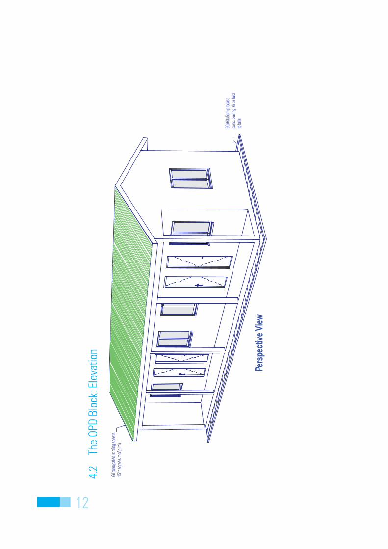
Indicative Construction Cost (see BoQs): 18,000 USD
The maternity block is designed to house an observation room and a delivery room. The third room (not inter-
connecting can be used inter-changeably (i.e. for ANC services).
This block can also be used to house a surgical theatre.
420 420 420
420
200
420
200
420 420 420
110
290
20 400 20 400 20 400 20
1,280
145 150 270 150 270 150 145
440
180
20
640
2040
020
180
20
125 150 125 20 125 150 125 20 125 150 12520
400
2018
020
640
145
150
145
180
20
60 150 80 90 100 150 80 90 60 90 80 150 60
20 400 20 400 20 400 20
1,280
20 400 20 400 20 400 20
+0.30 +0.30 +0.30
0.00
+0.15+0.15
03
A
A 02
01
04
60x60x5cmprecast concretepaving slabslaid to falls
100mm diaPVC RWP
line of roofoverhang below
100mm diaPVC RWP
100mm diaPVC RWP
Room 01ceramic tiles
Room 03ceramic tiles
Room 02ceramic tiles
beam abovestep up
beam abovestep up
beam abovestep up
Covered verandahceramic tiles
A B C D
1
2
3
1
2
3
A B C D
beam
abo
ve
beam
abo
ve
step up step up step up
Ground Floor Plan scale 1:100
Page 14
4.4
The
Mat
erni
ty: E
leva
tion.
G
I cor
ruga
ted
roo
fing
shee
ts15
o d
egre
es r
oof
pitc
h
60x6
0x5
cm p
reca
stco
nc. p
avin
g sl
abs
laid
to fa
lls
Pers
pect
ive
Vie
w
14
Page 15
15
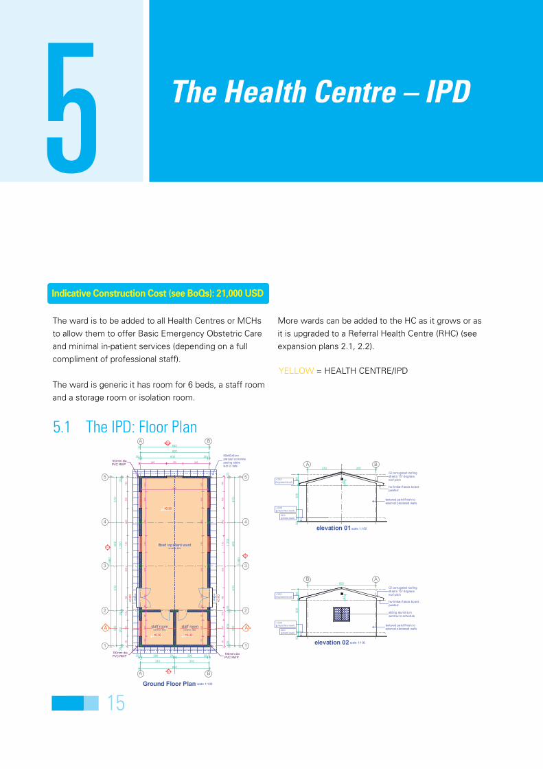
TheHealthCentre–IPD5Indicative Construction Cost (see BoQs): 21,000 USD
YELLOW = HEALTH CENTRE/IPD
5.1 The IPD: Floor Plan
640
20 290 20 290 20
201,
200
2030
020
320
410
400
410
1,56
0
7515
075
2018
032
515
025
515
012
0
20 600 20
640
620
600
245 150 245
7515
075
2018
032
515
025
515
012
0
9515
011
518
032
515
025
515
014
0
2030
020
1,20
020
1,56
0
320
410
400
410
9515
011
518
032
515
025
515
014
0
310 310
620
47
3030
098
47
3030
098
310310
+0.30 +0.30
+0.30
+0.
00
+0.
00
A A
01
03
04
02
60x60x5cmprecast concretepaving slabslaid to falls
100mm diaPVC RWP
100mm diaPVC RWP
100mm diaPVC RWP
0.00(ground level)
+0.30(ground floor level)
+3.30(ring beam level)
textured paint finish toexternal plastered walls
hw timber fascia boardpainted
GI corrugated roofingsheets 15o degreesroof pitch
sliding aluminiumwindow to schedule
0.00(ground level)
+0.30(ground floor level)
+3.30(ring beam level)
hw timber fascia boardpainted
GI corrugated roofingsheets 15o degreesroof pitch
textured paint finish toexternal plastered walls
A B
1
2
3
4
5
1
2
3
4
5
staff roomceramic ti les
8bed inpatient wardceramic tiles
A B
staff roomceramic tiles
step
up
step
up
elevation 02 scale 1:100
B A
elevation 01scale 1:100
A B
Ground Floor Plan scale 1:100
The ward is to be added to all Health Centres or MCHs
to allow them to offer Basic Emergency Obstetric Care
and minimal in-patient services (depending on a full
compliment of professional staff).
The ward is generic it has room for 6 beds, a staff room
and a storage room or isolation room.
More wards can be added to the HC as it grows or as
it is upgraded to a Referral Health Centre (RHC) (see
expansion plans 2.1, 2.2).
Page 16
16
5.2 The IPD: Elevation
300
98
320 410 400 410
300
98
410 400 410 320
0.00(ground level)
+0.30(ground floor level)
+3.30(ring beam level)
hw timber fascia boardpainted
textured paint finish toexternal plastered walls
GI corrugated roofingsheets 15o degreesroof pitch
sliding aluminiumwindow to schedule
0.00(ground level)
+0.30(ground floor level)
+3.30(ring beam level)
hw timber fascia boardpainted
textured paint finish toexternal plastered walls
GI corrugated roofingsheets 15o degreesroof pitch
sliding aluminiumwindow to schedule
15.0 deg.
scale 1:100
15
elevation 04
4 3 2
elevation 03
15.0 deg.
scale 1:100
15 4 3 2
60x60x5cm precastconc. paving slabs laidto falls
GI corrugated roofingsheets 15o degreesroof pitch
sliding aluminiumwindow to schedule
Side / Front Perspective Front / Rear Perspective
Page 17
17
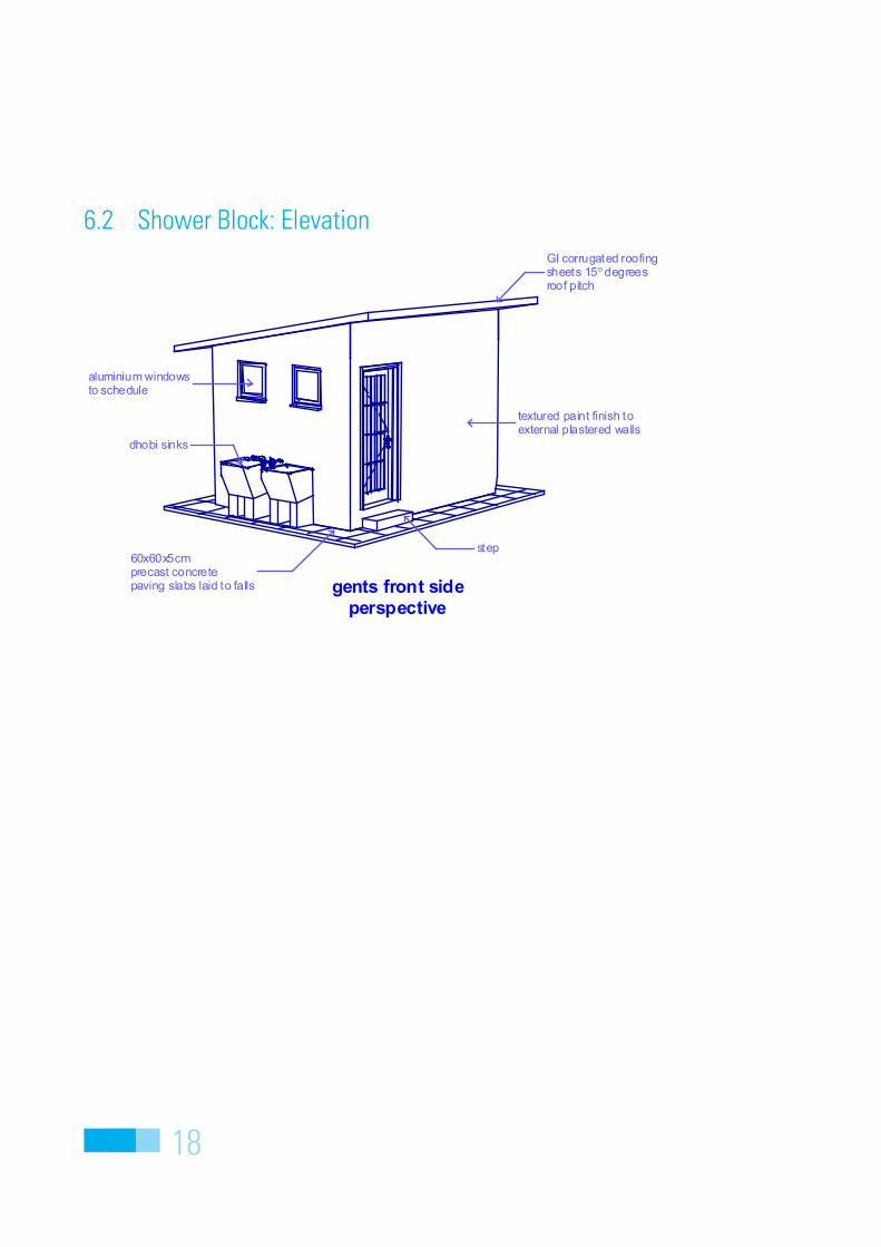
ShowerBlock6Indicative Construction Cost (see BoQs): 7,000 USD
The shower block is a wash place for people, clothes etc intended for all facilities with an in-patient capacity.
6.1 Shower Block: Floor Plan
2016
020
180
20
20 12020
120 20
50 60 80 60 50
300
140 140
20 12020
120 20
300
140 140
60 60 60 60 60
400
180
200
2016
020
180
20
400
180
200
3090
280
3090
280
240
90
140 140
240
140 140
+0.15 +0.15
0.00
03
04
02
01
B B
A
A
10cm diaPVC RWP
60x60x5cmprecast concretepaving slabslaid to falls
line of roof overhangabove
+0.30(ground floor level)
+2.70(ring beam level)
0.00(ground level)
GI corrugated roofingsheets 15o degreesroof pitch
aluminium windowsto schedule
textured paint finish toexternal plastered walls
dhobi sinks
+0.30(ground floor level)
+2.70(ring beam level)
0.00(ground level)
textured paint finish toexternal plastered walls
aluminium windowsto schedule
GI corrugated roofingsheets 15o degreesroof pitch
shwr shwr
gentsceramic tiles
ladiesceramic tiles
whbwhb
A B
A B
1
2
1
2
Ground Floor Plan (Shower Block)scale 1:100
dhobisinks
dhobisinks
scale 1:100elevation 01
A B
scale 1:100
AB
elevation 02
Page 18
18
6.2 Shower Block: Elevation
textured paint finish toexternal plastered walls
GI corrugated roofingsheets 15o degreesroof pitch
aluminium windowsto schedule
dhobi sinks
step60x60x5cmprecast concretepaving slabs laid to falls gents front side
perspective
Page 19
19
ToiletBlock7The toilet block should be seriously considered for all
levels of facility (even PHUs). The numbers of toilet
blocks will necessarily rise or fall depending on patient
volumes and IPD facilities/volumes.
In this report we have detailed a toilet block served by
running water and septic tank (toilet block) and a more
simple option for pit latrines draining into a pit.
7.1 Toilet Block: Floor Plan
Indicative Construction Cost (see BoQs): 16,500 USD
450
209015
9020
9015
9020
35 60 45 60 50 60 45 60 35
480
2010
015
150
1516
020
20195201952030 450 30
3020
8080
6024
030
430
460
430 460
430 460
-0.15
±0.00 ±0.00
-0.15
-0.30
-0.30
01
03 H
H
GG
0204
20X20cm RCcolumns
60X60cm precastpaving slabs
+0.000(grond floor level)
-0.300(ground level)
+2.700(ring beam level)
+0.000(grond floor level)
-0.300(ground level)
+2.700(ring beam level)
aluminium windowsto schedule
textured paint finish toexternal plastered walls
GI corrugatedroofing sheets
door to schedule
WC WC WC WC
Ground Floor Plan(toilet block) scale 1:100
step up
whb whb
step uplobby
2
1
ladiesceramic tiles
gentsceramic tiles
lobby
step
up
step
up
A B
scale 1:100
scale 1:100
scale 1:100
scale 1:100
A B
AB 1 2
12
elevation 01 elevation 02
elevation 03 elevation 04
Page 20
20
7.2 Toilet Block: Elevation
Rear Side Perspectiveof Toliet Block
Front Side Perspectiveof Toliet Block
7.3 Latrine (Pit) Block: Floor Plan
Indicative Construction Cost (see BoQs): 8,000 USD
8023
4
35 60 45 60 50 60 45 60 35
209015
9020
9015
9020
450
450
201952019520
2080
234
2012
015
160
20
430
430
314
314
240
240
240
430
430 314
314
7031
470
430
30 450 30
6033
460
-0 .15
-0.3
0
-0 .30
-0.15GG
04
01
02
03 H
H
60X60cm precastpaving slabs
-0.300(ground level)
+2.700(ring beam level)
aluminium windowsto schedule
textured paint finish toexternal p lastered walls
door to schedule
+0.000(ground floor level)
-0.300(ground level)
+2.700(ring beam level)
door to schedule
textured paint finish toexternal plastered walls textured paint finish to
external plastered walls
opening wi thmosquito gauze
+0.000(ground floor level)
15cm dia.metalvent pipe
15cm dia.metalvent pipe
100mm diaPVC RWP
15cm wide PVCrain water gutters
building line below
GI corrugated roofingsheets 10o degreesroof pitch
edge of undergroundpit walls
1
ladiesceramic tiles
gentsceramic tiles
A B
2
scale 1:100
Ground Floor Plan(latrine block)
latrine latrine latrine latrine
scale 1:100scale 1:100elevation 03 elevation 04
AB
scale 1:100scale 1:100elevation 01 elevation 02
A B 12
1 2
A B
slop
e
slope of gutter
1
slop
e
2
scale 1:100
Roof Plan showingslopes (latrine block)
Page 21
21
7.4 Latrine (Pit) Block: Elevation
60X60cm precastpaving slabs step
removabe slabfor pit emptying
GI corrugated roofingsheets 10o degreesroof pitch
15cm dia.metalvent pipe
Front Side Perspectiveof Latrine Block
handledoor to schedule
window toschedule
removabe slabfor pit emptying
handle60X60cm precastpaving slabs
step
15cm dia.metalvent pipe
GI corrugated roofingsheets 10o degreesroof pitch
Rear Side Perspectiveof Latrine Block
Page 22
22
WasteDisposal8Indicative Construction Cost (see BoQs): 700 USD
Medical waste is a serious issue. During construction
of any level of facility – plans must be made for medical
waste disposal. For larger facilities producing large
quantities of dangerous medical waste an incinerator
is highly recommended despite the additional costs of
construction.
All facilities will need a waste pit to burry medical waste
and this pit should not be open to the public/playing
children.
8.1 Incinerator: Floor Plan
100
200
187
111
1165
111
200
1276
121115
2515
11
1317512
111
1154
111
11
100
100
200
111
1154
111
11
111
1154
111
11
187
132592252611111
13111
119223261111113111291232611111
100
1276
12
1276
12
187
17 36 47 36 51
1265
12
110mm wide fire clay brick wallfor the main body of incinerator
primarycombustion chamber
110mm wide outer fire claybrick wall of the incinerator
3mm thick MS plate ash door on30x30x3mm MS angle frame,oil painted to approval.
110mm wide fire clay brick wallfor the main body of incinerator
110mm wide outer fire claybrick wall of the incinerator
3mm thick MS platebox tunnel
fire clay bricks asthe base for the incinerator
110mm wide outer fire claybrick wall of the incinerator
110mm wide fire clay brick wallfor the main body of incinerator
150x230mm RC lintel tosupport bricks above
primarycombustion chamber
110mm wide outer fire claybrick wall of the incinerator
flue and secondarycombust ion chamber
flue and secondarycombust ion chamber
MS hinges to siteEngineer's approval
loading door of 3mm MS platewelded on 30x30x3mm MSangle frame, oil painted.
3mm thick MS plate cover with114mm dia, 3mm thick MS pipewelded on 30x30x3mm MS angleframe to house the chimney
170x250mm RC lintel tosupport bricks above
scale 1:25Floor Plan at 02
scale 1:25Floor Plan at 01 scale 1:25Floor Plan at 03
scale 1:25Floor Plan at 04
Page 23
23
8.2 Incinerator: Elevation
114
4m h
eigh
t
733
1751
516
733
1751
516
733
1751
516
114
+0.000(floor level)
+1.090(6course brick leve l)
+1.300(incinerator top level)
+0.410(4course brick leve l)
+0.580(2course brick leve l)
+0.075(incinerator base level )
150mm dia,3mm thick MSpipe chimney welded ontothe chimney base plate
40x100x5mm MS channelsection as the top frame
loading door handle
loading door of 3mmMS plate welded on30x30x3mm MS angleframe, oil painted to approval.
110mm wide outer fire claybrick wall of the incinerator
3mm thick MS plate ash door on30x30x3mm MS angle frame,oil painted to approval.
fire clay bricks asthe base for the incinerator
3mm thick MS plate ash door on30x30x3mm MS angle frame,oil painted to approval.
150mm dia,3mm thick MSpipe chimney welded ontothe chimney base plate
loading door of 3mmMS plate welded on30x30x3mm MS angleframe, oil painted to approval.
110mm wide outer fire claybrick wall of the incinerator
fire clay bricks asthe base for the incinerator
150x230mm RC lintel tosupport bricks above
typical side elevation scale 1:25 rear elevationscale 1:25
front elevationscale 1:25
More detailed and scaled drawings are available with BoQs on the attached diskette. Drawings should be printed
on A3 format paper
chimney rain cap
the gaps between the brick jointsas well as the gap between theinner wall and the outer wallcan be filled with refactory cement
2 coats of anti-rust paintto inhibit corrosion to allthe mild steel surfaces
2 coats of anti-rust paintto inhibit corrosion to allthe mild steel surfaces
Completed Incinerator