Construction Inspection with Stakeless Technology 3D Modeling Technology QA\QC using Rovers Richard E. McDaniel STS/Design Visualization Specialist/CADD Manager FHWA / EFLHD Sterling, VA Troy Wheeler Mapping Engineer FHWA / EFLHD Sterling, VA
Transcript
Construction Inspection with Stakeless Technology
3D Modeling Technology QA\QC using Rovers
Richard E. McDaniel STS/Design Visualization Specialist/CADD Manager FHWA / EFLHD Sterling, VA
Troy Wheeler Mapping Engineer FHWA / EFLHD Sterling, VA
3D Modeling Technology QA\QC using Rovers
Item we will cover today
• What is 3D Modeling?
• Benefits of using 3D Modeling Technology in Construction
• Construction Site QA/QC using a Rover
• 3D Modeling Construction Specifications
3D Modeling Technology QA\QC using Rovers
What is 3D Modeling
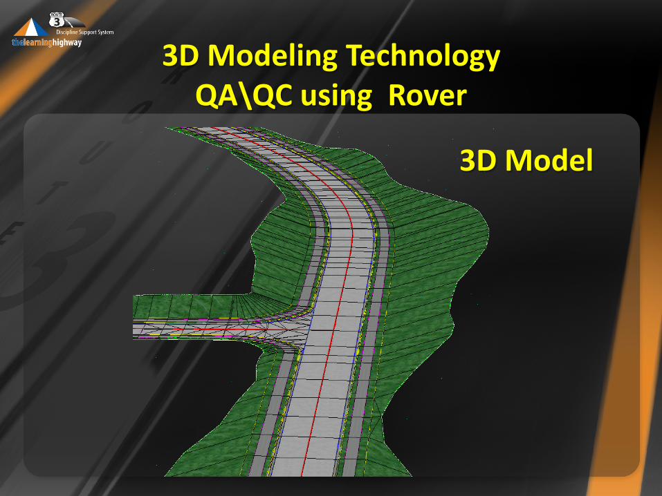
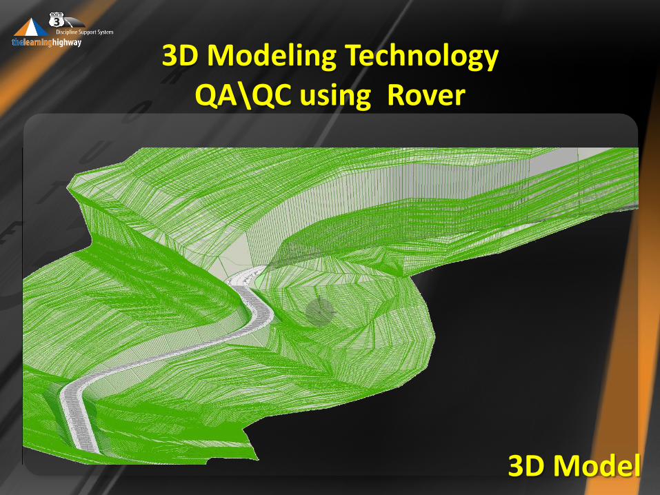
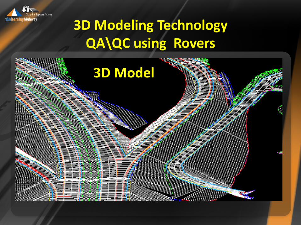
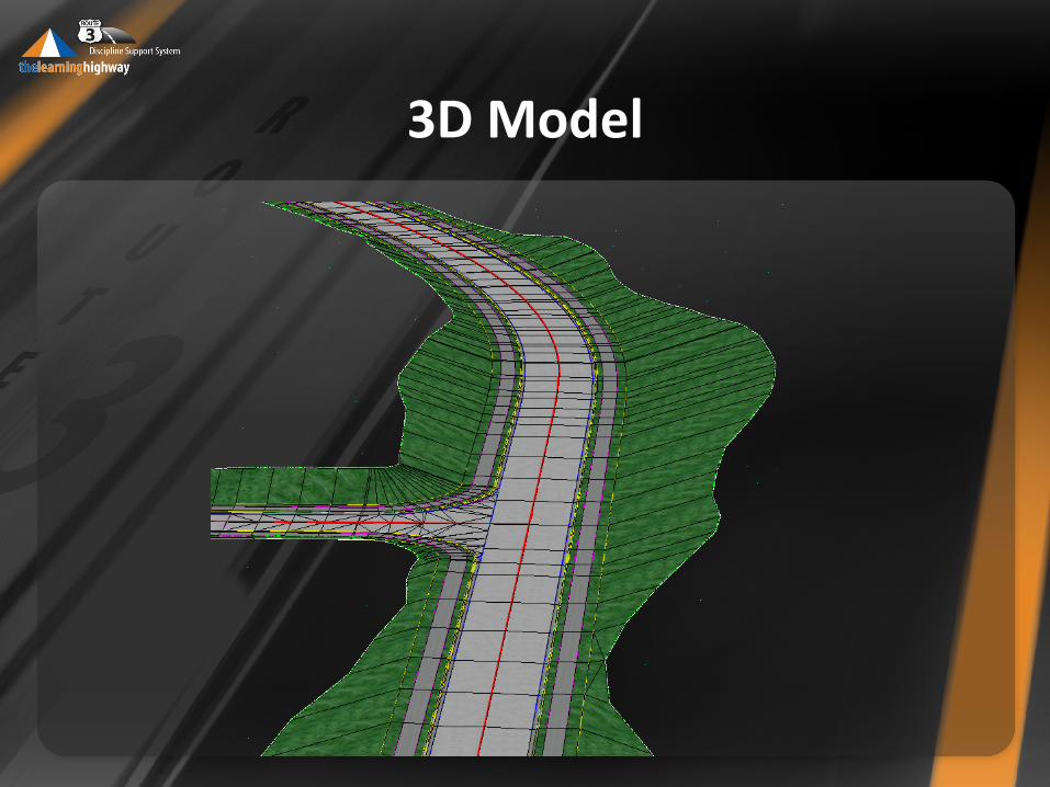
A three dimensional model is created using a set of points in space, that are connected by various geometric data such as lines, and curved elements, in our case the design surface of a highway segment.
3D Modeling Technology QA\QC using Rover
3D Model
3D Modeling Technology QA\QC using Rover
3D Model
3D Modeling Technology QA\QC using Rovers
3D Model
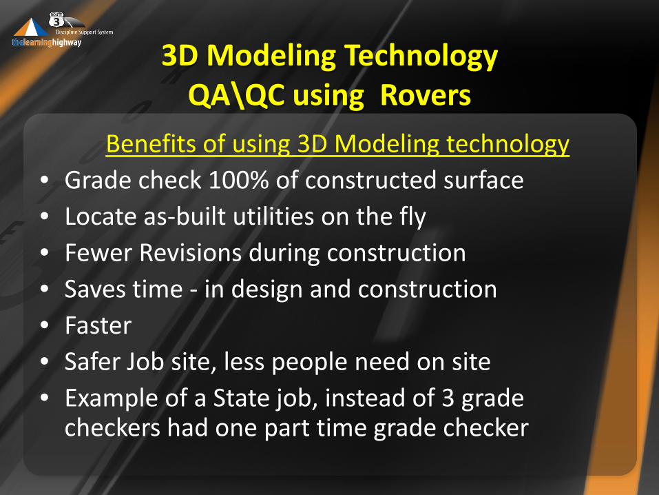
Benefits of using 3D Modeling technology • Grade check 100% of constructed surface • Locate as-built utilities on the fly • Fewer Revisions during construction • Saves time - in design and construction • Faster • Safer Job site, less people need on site • Example of a State job, instead of 3 grade
checkers had one part time grade checker
3D Modeling Technology QA\QC using Rovers
3D Modeling Technology QA\QC using Rovers
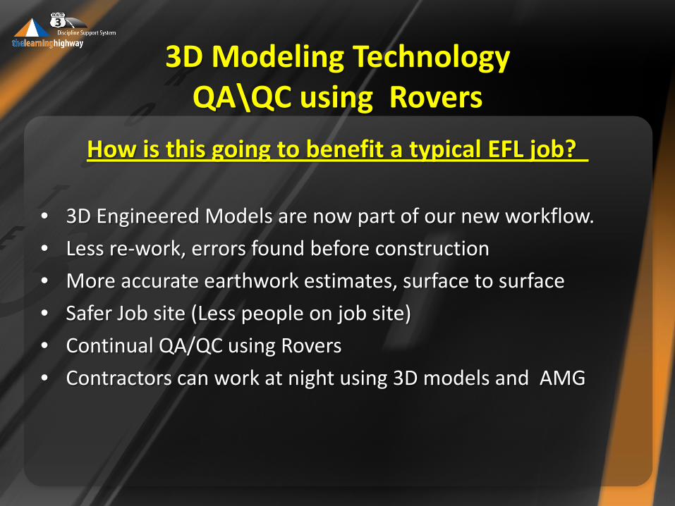
How is this going to benefit a typical EFL job?
• 3D Engineered Models are now part of our new workflow.
• Less re-work, errors found before construction
• More accurate earthwork estimates, surface to surface
• Safer Job site (Less people on job site)
• Continual QA/QC using Rovers
• Contractors can work at night using 3D models and AMG
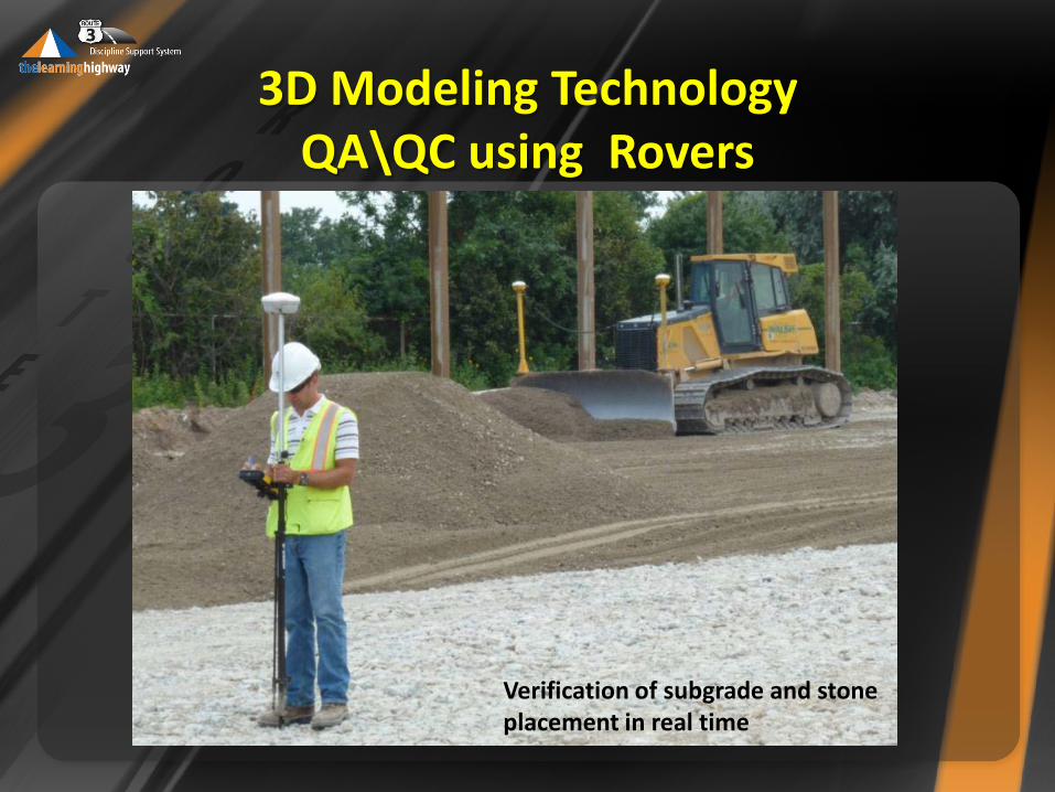
Verification of subgrade and stone placement in real time
3D Modeling Technology QA\QC using Rovers
3D Modeling Technology QA\QC using Rovers
Benefits of using 3D Modeling technology
• GPS on dozer and blade
• “I can see one day not to far into the future we no longer get plans, just a chip to load into the equipment” Clayton Gladen, President, Gladen Construction.
• No second guessing (elevations or grade)
3D Modeling Technology QA\QC using Rovers
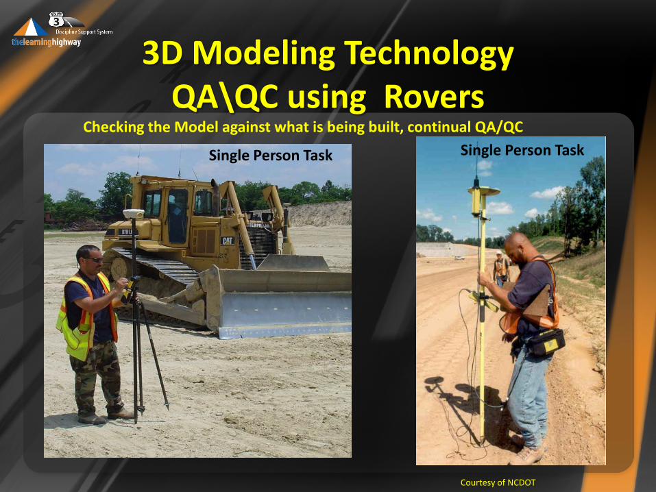
Courtesy of NCDOT
Checking the Model against what is being built, continual QA/QC
Single Person Task Single Person Task
Some Rover Field Uses • Grade checks
• Structures
• Wall alignments
• Sign bridge footings
• Structure excavation
• Culvert invert elevations
• Pavement marking layout
• Pay quantity measurements
3D Modeling Technology QA\QC using Rovers
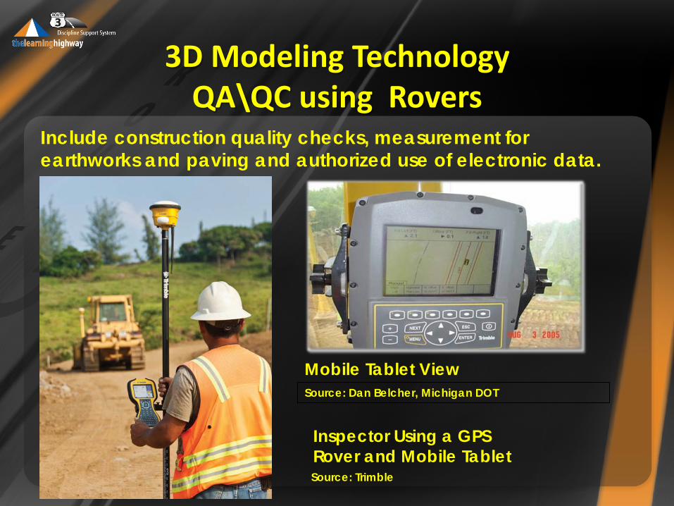
Source: Trimble
Mobile Tablet View
Inspector Using a GPS Rover and Mobile Tablet
Source: Dan Belcher, Michigan DOT
Include construction quality checks, measurement for earthworks and paving and authorized use of electronic data.
3D Modeling Technology QA\QC using Rovers
3D Modeling Technology QA\QC using Rovers
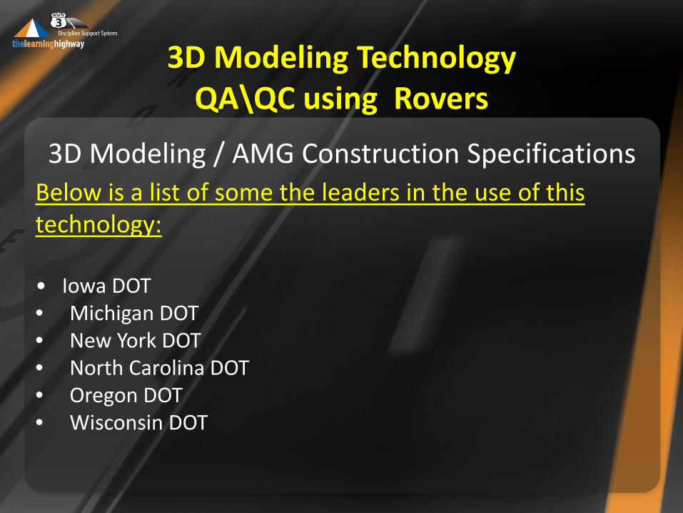
3D Modeling / AMG Construction Specifications Below is a list of some the leaders in the use of this technology: • Iowa DOT • Michigan DOT • New York DOT • North Carolina DOT • Oregon DOT • Wisconsin DOT
3D Modeling Technology QA\QC using Rovers
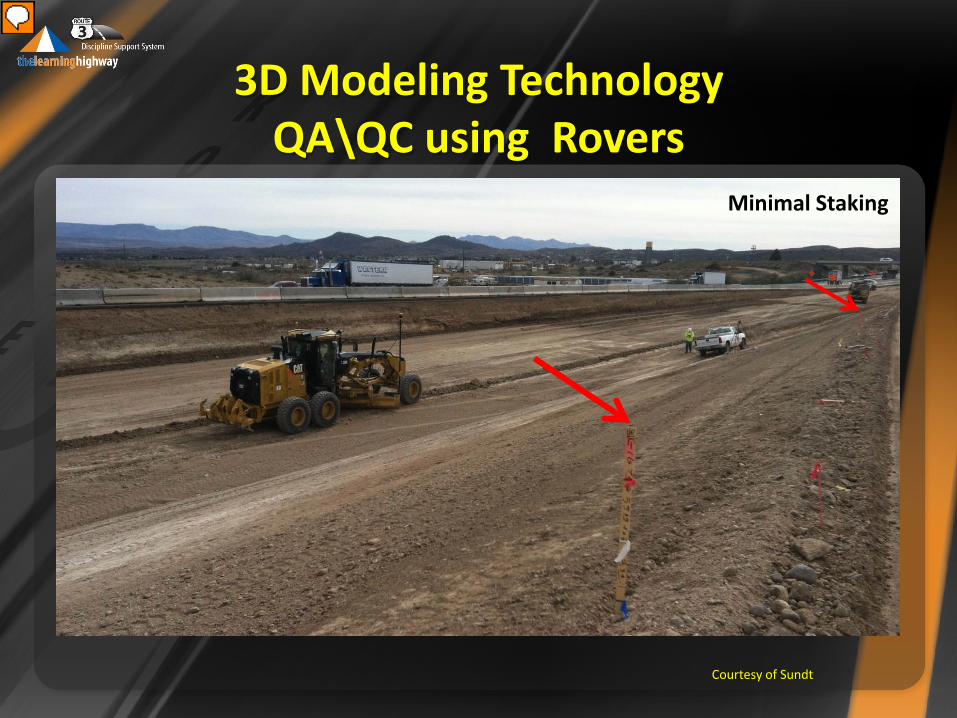
Courtesy of Sundt
Minimal Staking
Presenter
Presentation Notes
Some location are still staked as benchmarks to check. A stakeless project is never stakeless, just less stakes.
3D Modeling Technology QA\QC using Rovers
EFLHD Rover Demo
Troy Wheeler
Mapping Engineer
FHWA/EFLHD
Sterling, VA
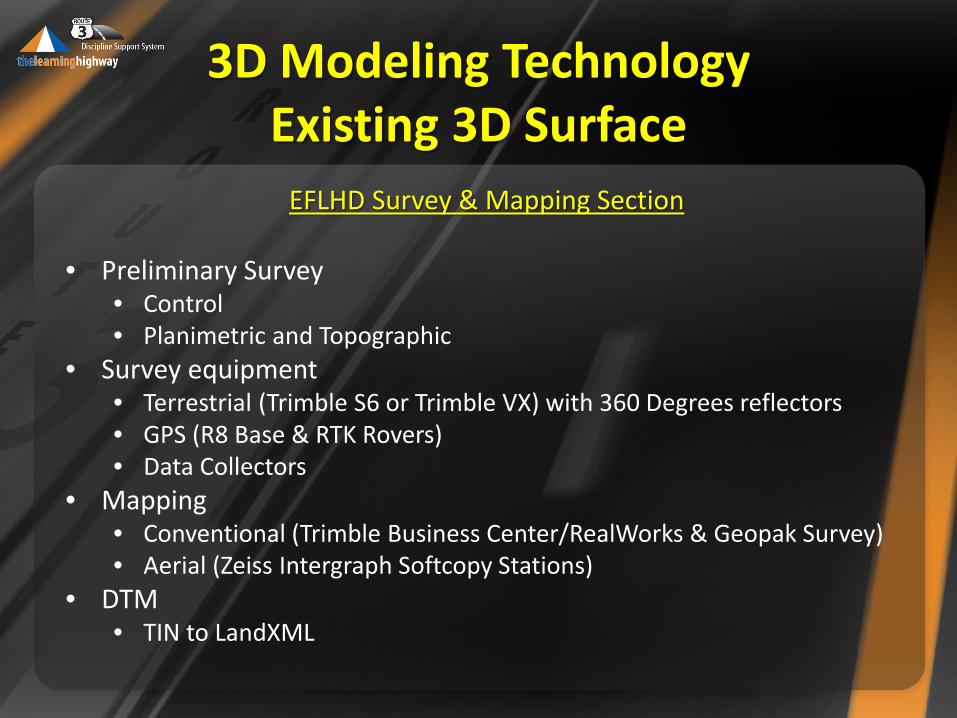
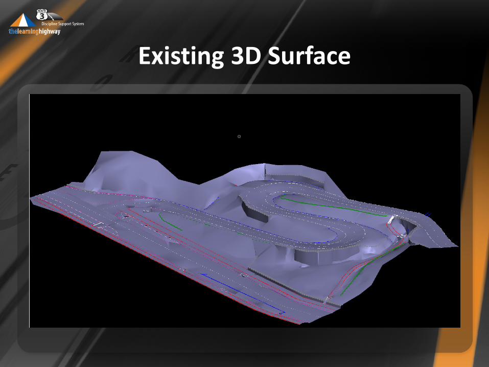
3D Modeling Technology Existing 3D Surface
EFLHD Survey & Mapping Section
• Preliminary Survey • Control • Planimetric and Topographic
• Survey equipment • Terrestrial (Trimble S6 or Trimble VX) with 360 Degrees reflectors • GPS (R8 Base & RTK Rovers) • Data Collectors
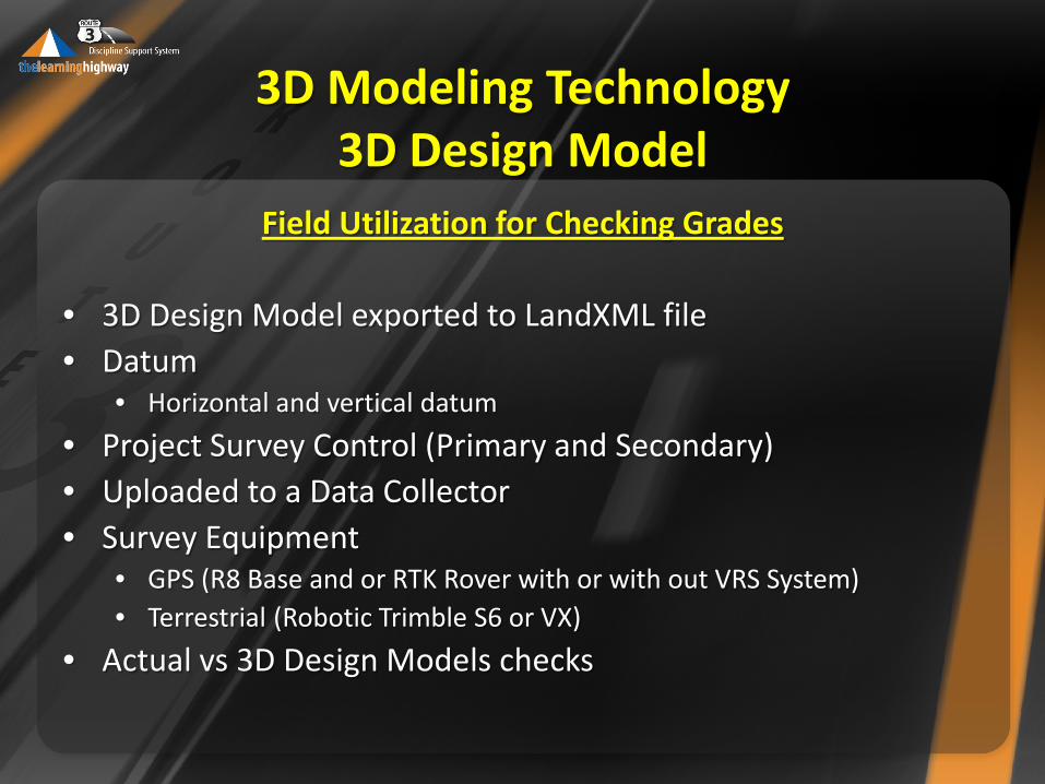
• 3D Design Model exported to LandXML file • Datum
• Horizontal and vertical datum
• Project Survey Control (Primary and Secondary) • Uploaded to a Data Collector • Survey Equipment
• GPS (R8 Base and or RTK Rover with or with out VRS System) • Terrestrial (Robotic Trimble S6 or VX)
• Actual vs 3D Design Models checks
3D Model
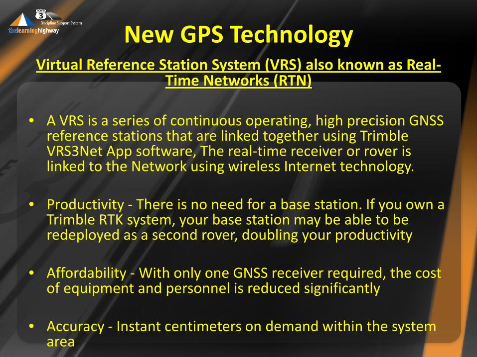
New GPS Technology Virtual Reference Station System (VRS) also known as Real-
Time Networks (RTN)
• A VRS is a series of continuous operating, high precision GNSS reference stations that are linked together using Trimble VRS3Net App software, The real-time receiver or rover is linked to the Network using wireless Internet technology.
• Productivity - There is no need for a base station. If you own a
Trimble RTK system, your base station may be able to be redeployed as a second rover, doubling your productivity
• Affordability - With only one GNSS receiver required, the cost
of equipment and personnel is reduced significantly
• Accuracy - Instant centimeters on demand within the system area
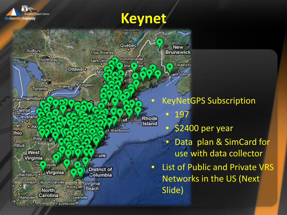
Keynet
• KeyNetGPS Subscription
• 197
• $2400 per year
• Data plan & SimCard for use with data collector
• List of Public and Private VRS Networks in the US (Next Slide)
Benefits of VRS System over traditional RTK Surveying
• The need for a user to establish a permanent/semi-permanent base station is eliminated and: • Eliminates the time for initial site selection and (daily) set-up.
• The Virtual Reference Station (VRS) can monitor its own integrity and can detect if there is a problem with a particular reference station. • Since the reference stations are part of a network, a loss of one station
does not result in failure of the entire network or the resulting survey.
• With a single-base Real Time Kinematic (RTK) setup it can be difficult to tell if a problem exists or occurs with a base station while conducting a survey.
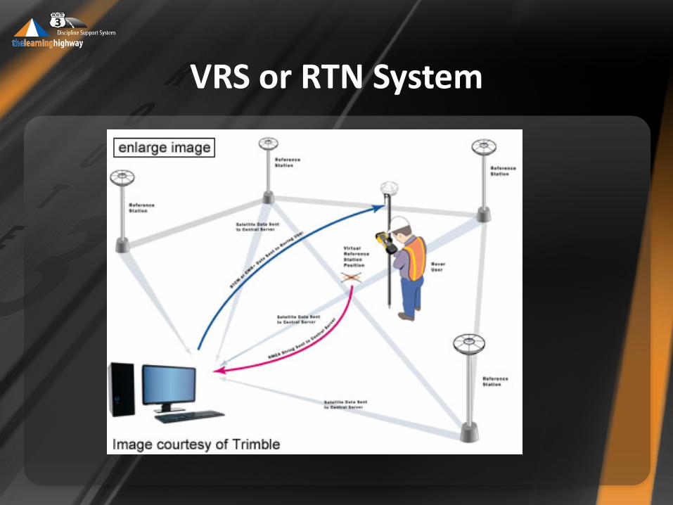
VRS or RTN System
• The loss of a reference station with single-base RTK setup results in the end of data collection
• With VRS surveying the system accuracy degrades gradually.
• A sufficiently dense reference station network can result in shorter baselines.
• As with any other style of GPS surveying, shorter baselines result in improved accuracy because of reduced effects of atmospheric interference.
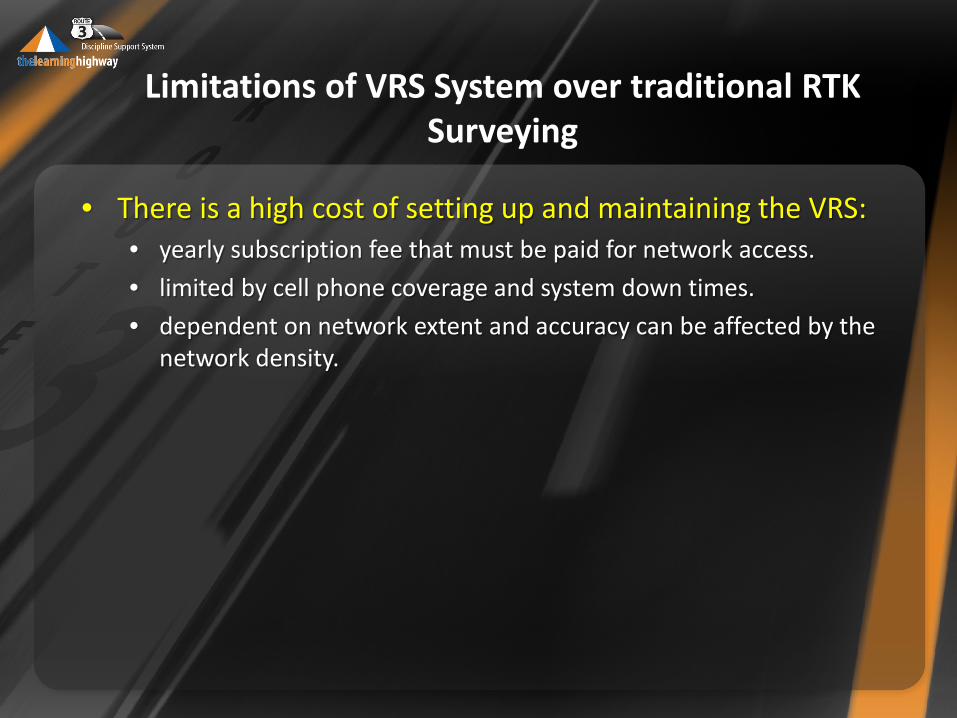
Limitations of VRS System over traditional RTK Surveying
• There is a high cost of setting up and maintaining the VRS: • yearly subscription fee that must be paid for network access.
• limited by cell phone coverage and system down times.
• dependent on network extent and accuracy can be affected by the network density.
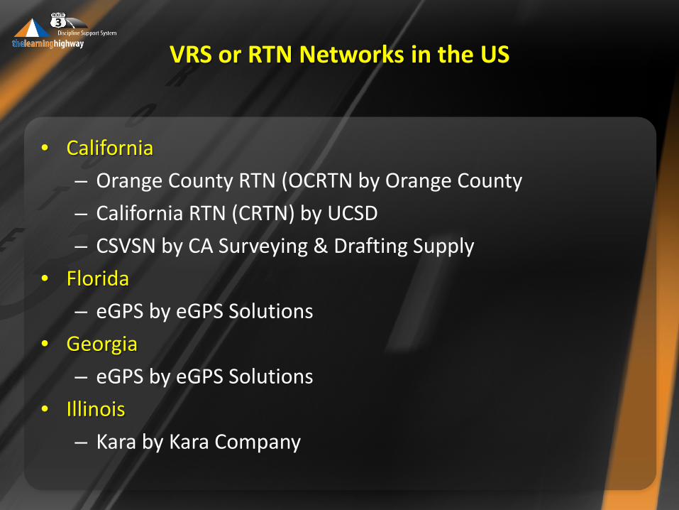
VRS or RTN Networks in the US
• California
– Orange County RTN (OCRTN by Orange County
– California RTN (CRTN) by UCSD
– CSVSN by CA Surveying & Drafting Supply
• Florida
– eGPS by eGPS Solutions
• Georgia
– eGPS by eGPS Solutions
• Illinois
– Kara by Kara Company
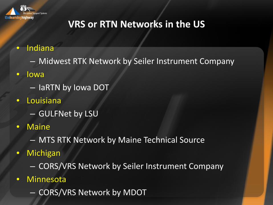
VRS or RTN Networks in the US
• Indiana
– Midwest RTK Network by Seiler Instrument Company
• Iowa
– IaRTN by Iowa DOT
• Louisiana
– GULFNet by LSU
• Maine
– MTS RTK Network by Maine Technical Source
• Michigan
– CORS/VRS Network by Seiler Instrument Company
• Minnesota
– CORS/VRS Network by MDOT
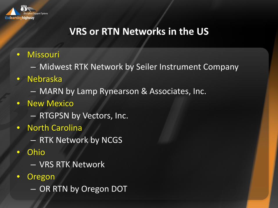
VRS or RTN Networks in the US
• Missouri – Midwest RTK Network by Seiler Instrument Company
• Nebraska – MARN by Lamp Rynearson & Associates, Inc.
• New Mexico – RTGPSN by Vectors, Inc.
• North Carolina – RTK Network by NCGS
• Ohio – VRS RTK Network
• Oregon – OR RTN by Oregon DOT
VRS or RTN Networks in the US
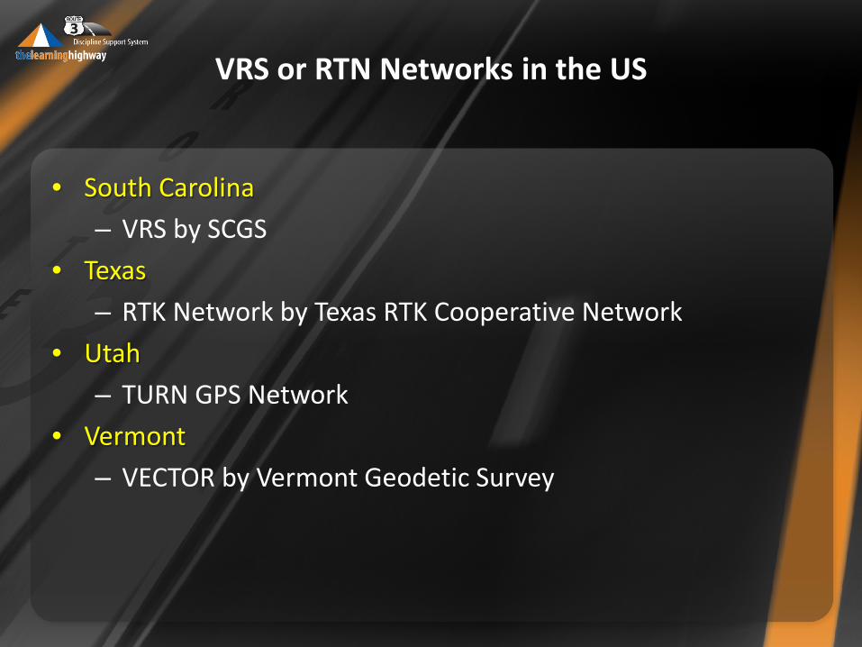
• South Carolina
– VRS by SCGS
• Texas
– RTK Network by Texas RTK Cooperative Network
• Utah
– TURN GPS Network
• Vermont
– VECTOR by Vermont Geodetic Survey
VRS or RTN Networks in the US
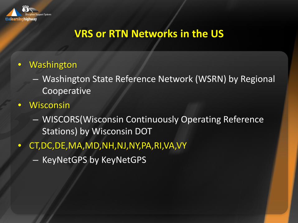
• Washington
– Washington State Reference Network (WSRN) by Regional Cooperative
• Wisconsin
– WISCORS(Wisconsin Continuously Operating Reference Stations) by Wisconsin DOT
• CT,DC,DE,MA,MD,NH,NJ,NY,PA,RI,VA,VY
– KeyNetGPS by KeyNetGPS
Reach out questions from construction
3D Modeling Technology QA\QC using Rovers
3D Modeling Technology QA\QC using Rovers
You say that NCDOT is a leader, what makes them a leader?
They have provided a process for this technology to be utilized and be able to perform checks to show accountability, however it is still only being used on a small percentage of our projects and mostly on larger grading projects.
Typical Problems found in the field
Early Problem: Lack of 3D modeling experience • Constructability • Contractor made correction on the fly
Ride quality: • Control in z plane • WISDOT has created a formula to calculate how many sections
are need on a curve to get a smooth curve on the ground.
3D Modeling Technology QA\QC using Rovers
How do you tell if the Rover isn’t functioning properly?
• Depending on which Manufacture and model you are using the
robotic (theodolite) instrument will give you an instrument error through the data collector.
• It will give an error code or the data collector will specifically say the temperatures are too cold.
• In temperatures 15 and below the instrument may not give you an error every time but you may get bogus measurements.
3D Modeling Technology QA\QC using Rovers
Is having a clear line of view required?
• If you are using the Robotic (theodolite) instrument you will
need a line of site.
• If you are using a GPS Trimble R3 or R4 model you will not need a line of site.
• You will need a clear overhead path to the sky. Too much canopy from trees, building or mountains will block some satellite views, which will inhibit the accuracy of your position.
3D Modeling Technology QA\QC using Rovers
3D Modeling Technology QA\QC using Rovers
How long does setup and verification take? • The contractor will typically take 20 minutes. • This is typically done at a monument that has set up and
verified with the owner’s control points. • If an AMG piece of equipment is modified during the shift,
recalibration of that equipment is required. • It is recommend that the owner use the same control
monuments for calibration as the contractor and same frequency.
• If there is any difference in accuracy of the owner’s QA tools from the Contractor’s , the error should be discovered quickly due to the calibration frequency.
Do they have an army of inspectors going to all their jobs checking grades? • Typical inspection staff supplemented as needed with DOT
survey crew
Do they require their contractors to verify their work in this manner? • You can’t be specific enough in describing how it’s being
used.
• Typically owners require a QC plan from the contractor, which should specify results without prescribing methods. Owners should also share their QA plan and coordinate ahead with contractors.
3D Modeling Technology QA\QC using Rovers
3D Modeling Technology QA\QC using Rovers What about using LIDAR?
Many State Survey groups are using mobile LiDar on large projects. LiDar is a great substitute to adding additional data (contours) to a project. • verifying hydraulic channels • verifying the terrain • verifying elevation While the physical LiDar equipment will typically last many years, the “guts” typically become obsolete after only three years.
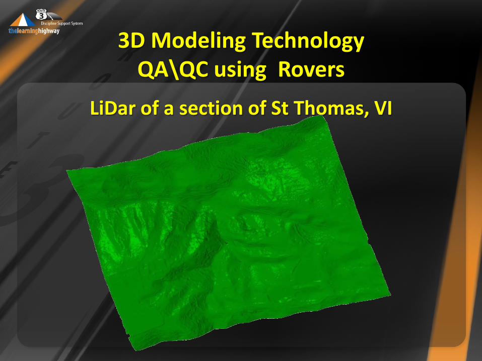
LiDar of a section of St Thomas, VI
3D Modeling Technology QA\QC using Rovers
3D Modeling Technology QA\QC using Rovers
How long for the post-processing of data, say for as-builts?
• Owner must specify details if as-built is desired
• The 3D model that is agreed upon as “The Model of Record” what the contractor has put on the ground, now becomes the as-built.
• Through-out the construction QA/QC has been done at a pre-determined locations and or distances.
3D Modeling Technology QA\QC using Rovers
What’s the level of accuracy?
• The accuracy is 0.0065 ft. That refers to S6 and VX instruments.
• The GPS accuracy is +/- 5 mm or 0.0164 ft.
• Tenth (0.10) for rough grading and centimeter for fine grading.
3D Modeling Technology QA\QC using Rovers
How do you calibrate the rovers? What level of expertise will the file person have to have to be able to work with equipment such as this. • Need various levels of experience from strong survey
understanding to technician level by grade checker/equipment operators. Each must understand their role and how to use the model effectively.
• Training for field inspectors might take eight hours, depending on the level of understanding required by the owner.
• Training for resident/project engineers takes longer (20+ hours, less than a week) because an owner will likely want to go deeper (e.g. “how the equipment functions “ and “how the equipment is calibrated”).
• It depends on how much theory and understanding of the rover/base station operation the owner expects his/her employees to know/ comprehend and apply.
3D Modeling Technology QA\QC using Rovers
EFLHD Rover Demo
Rover setup
Identify tools on Rover
How it works
Questions on Rover Demo
3D Modeling Technology QA\QC using Rovers
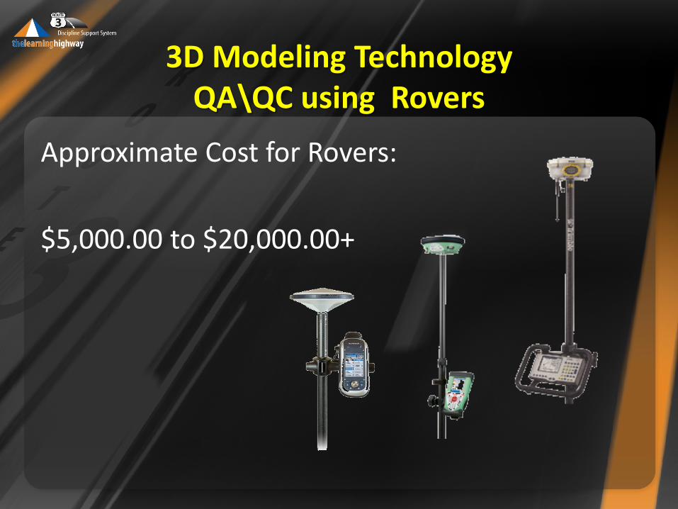
Approximate Cost for Rovers:
$5,000.00 to $20,000.00+
3D Modeling Technology QA\QC using Rovers
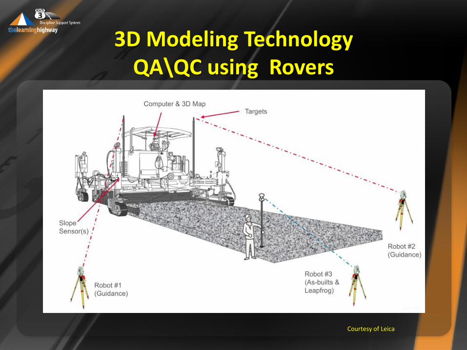
Source: Leica
Courtesy of Leica
3D Modeling Technology QA\QC using Rovers
Some Building blocks in writing a good 3D Engineered Model for Construction
Specifications
Some Building blocks in writing a good 3D Engineered Model for Construction Specifications
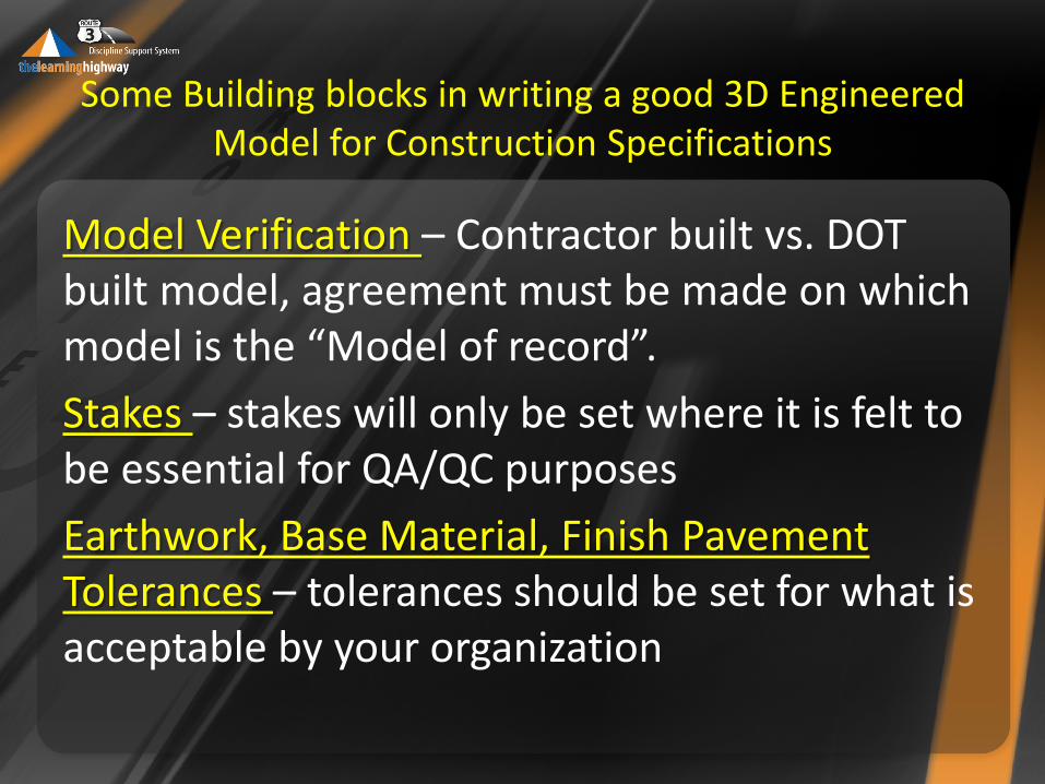
Model Verification – Contractor built vs. DOT built model, agreement must be made on which model is the “Model of record”.
Stakes – stakes will only be set where it is felt to be essential for QA/QC purposes
Earthwork, Base Material, Finish Pavement Tolerances – tolerances should be set for what is acceptable by your organization
Some Building blocks in writing a good 3D Engineered Model for Construction Specifications
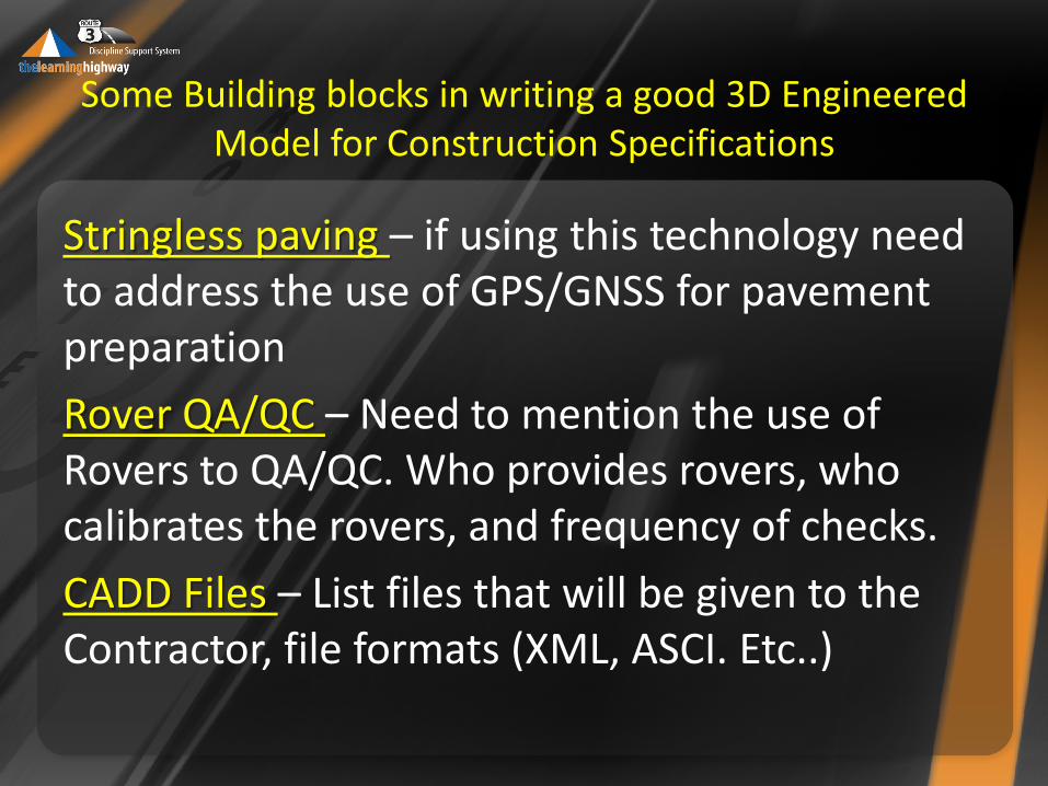
Stringless paving – if using this technology need to address the use of GPS/GNSS for pavement preparation
Rover QA/QC – Need to mention the use of Rovers to QA/QC. Who provides rovers, who calibrates the rovers, and frequency of checks.
CADD Files – List files that will be given to the Contractor, file formats (XML, ASCI. Etc..)
3D Modeling Technology QA\QC using Rovers
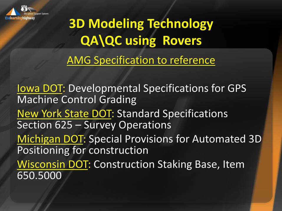
AMG Specification to reference
Iowa DOT: Developmental Specifications for GPS Machine Control Grading New York State DOT: Standard Specifications Section 625 – Survey Operations Michigan DOT: Special Provisions for Automated 3D Positioning for construction Wisconsin DOT: Construction Staking Base, Item 650.5000
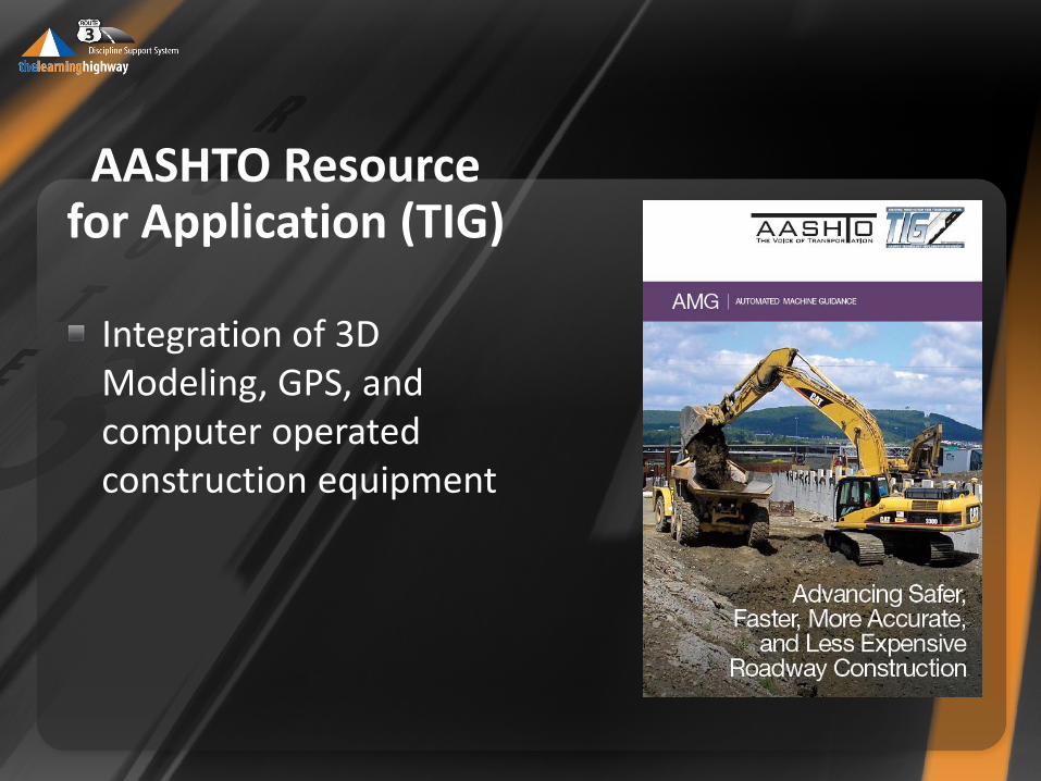
AASHTO Resource for Application (TIG)
Integration of 3D Modeling, GPS, and computer operated construction equipment
3D Modeling Technology QA\QC using Rovers
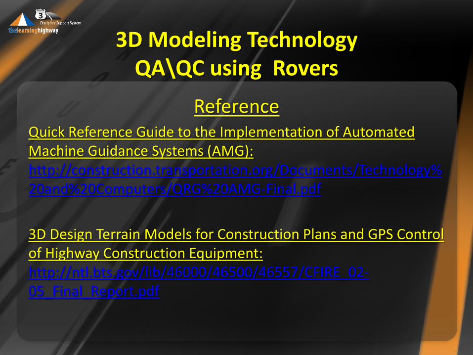
Reference Quick Reference Guide to the Implementation of Automated Machine Guidance Systems (AMG): http://construction.transportation.org/Documents/Technology%20and%20Computers/QRG%20AMG-Final.pdf
3D Design Terrain Models for Construction Plans and GPS Control of Highway Construction Equipment: http://ntl.bts.gov/lib/46000/46500/46557/CFIRE_02-05_Final_Report.pdf
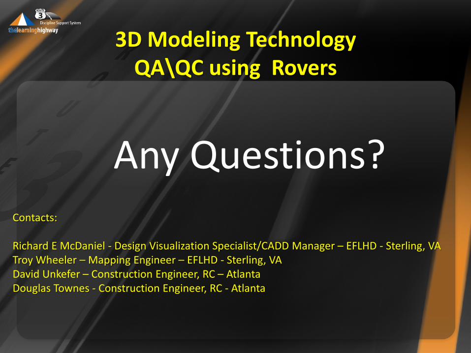
Any Questions? Contacts: Richard E McDaniel - Design Visualization Specialist/CADD Manager – EFLHD - Sterling, VA Troy Wheeler – Mapping Engineer – EFLHD - Sterling, VA David Unkefer – Construction Engineer, RC – Atlanta Douglas Townes - Construction Engineer, RC - Atlanta