89
Construction of Petri net based models for C programs Kulwant Singh

Construction of Petri net based modelsfor C programs
Kulwant Singh

Construction of Petri net based modelsfor C programs
Thesis submitted toIndian Institute of Technology, Kharagpur
for the award of the degree
of
MASTER OF TECHNOLOGY(2014-16)
by
Kulwant Singh
14CS60R20
under the guidance of
Prof. Dipankar Sarkar
Department of Computer Science & EngineeringIndian Institute of Technology, Kharagpur
May 2016

ii

DECLARATION
I certify that
a. the work contained in this report is original and has been done by me underthe guidance of my supervisor.
b. the work has not been submitted to any other institute for any degree ordiploma.
c. I have followed the guidelines provided by the institute in preparing thereport.
d. I have conformed to the norms and guidelines given in the Ethical Code ofConduct of the Institute.
e. Whenever I have used materials (data, theoretical analysis, figure, and text)from other sources, I have given due credit to them by citing them in thetext of the report and giving their details in the references.
Kulwant Singh
iii

iv

CERTIFICATE
This is to certify that the project report entitled “Construction of Petri netbased models for C programs”, submitted by Kulwant Singh (14CS60R20), of theDepartment of Computer Science and Engineering, Indian Institute of Technol-ogy, Kharagpur, India, for the award of the degree of Master of Technology, is arecord of an original research work carried out by him under my supervision andguidance. The report fulfills all the requirements as per the regulations of thisinstitute. Neither this report nor any part of it has been submitted for any degreeor academic award elsewhere to the best of my knowledge .
Prof. Dipankar SarkarDepartment of CSE
IIT Kharagpur
v

vi

Acknowledgments
Though only my name appears on the cover of this dissertation, a great manypeople have contributed to its completion. I owe my gratitude to all those peoplewho have made this dissertation possible and because of whom my graduate ex-perience has been one that I will cherish forever.
My deepest gratitude is to my adviser, Prof. Dipankar Sarkar. His patience,immense knowledge and support helped me finish this dissertation. I feel fortu-nate to have him as my adviser.
Besides my adviser, I would like to thank Prof. Chittaranjan Mandal for hisguidance at various junctures.
I would also like to thank Soumyadip Bandyopadhyay, Ph.D. student underthe supervision of my adviser, for his guidance and help.
A special thanks to my family. Their support and prayers for me has sustainedme thus far. I would also like to thank all my friends who supported me duringthe course of this degree.
Kulwant Singh
vii

viii
Abstract
Compilers carry out extensive optimizing transformations on the source pro-grams exploiting the data independence of operations. Their validation is achievedby establishing behavioural equivalence between the source and the transformedprograms. Models capturing data independence of operations by parallelism aremost suitable for the purpose. Accordingly, Petri net based models of programsare more suitable then cfgs (Control Flow Graphs) like FSMDs (Finite State Ma-chines with Datapaths) and CSPs (Concurrent Sequential Processes). If suitablyconstructed, the Petri net based models of the source and the transformed pro-grams often become structurally similar thereby making the task of establishingequivalence between them easier. Experience with equivalence checking using sucha Petri net based models, called PRES+ (Petri net based Representation of Embed-ded Systems), have been encouraging. No tools for automated construction of thePRES+ models from high level language programs are available. In this paper wepresent a tool for the automated construction of PRES+ models from C programs.
ix

x
Contents
Title Page . . . . . . . . . . . . . . . . . . . . . . . . . . . . . . . . . . . . i
Declaration . . . . . . . . . . . . . . . . . . . . . . . . . . . . . . . . . . . iii
Certificate . . . . . . . . . . . . . . . . . . . . . . . . . . . . . . . . . . . . v
Acknowledgments . . . . . . . . . . . . . . . . . . . . . . . . . . . . . . . vii
Abstract . . . . . . . . . . . . . . . . . . . . . . . . . . . . . . . . . . . . . ix
1 Introduction . . . . . . . . . . . . . . . . . . . . . . . . . . . . . . . . . 11.1 Aim of the work . . . . . . . . . . . . . . . . . . . . . . . . . . . . . 11.2 Organization of the thesis . . . . . . . . . . . . . . . . . . . . . . . 2
2 PRES+ model . . . . . . . . . . . . . . . . . . . . . . . . . . . . . . . . . 32.1 Definition of PRES+ net . . . . . . . . . . . . . . . . . . . . . . . . . 32.2 An example of PRES+ model . . . . . . . . . . . . . . . . . . . . . . 3
3 Implementation . . . . . . . . . . . . . . . . . . . . . . . . . . . . . . . 73.1 Input specification . . . . . . . . . . . . . . . . . . . . . . . . . . . 83.2 Output specification . . . . . . . . . . . . . . . . . . . . . . . . . . 83.3 Data Structures for the control flow graph . . . . . . . . . . . . . . 10
3.3.1 Symbol Table . . . . . . . . . . . . . . . . . . . . . . . . . . 103.3.2 BB array (Array of basic blocks) . . . . . . . . . . . . . . . 113.3.3 Basic block . . . . . . . . . . . . . . . . . . . . . . . . . . . 113.3.4 Statement . . . . . . . . . . . . . . . . . . . . . . . . . . . . 133.3.5 Expression Tree . . . . . . . . . . . . . . . . . . . . . . . . . 14
3.4 Data Structures for the PRES+ model . . . . . . . . . . . . . . . . . 153.4.1 Pres Plus . . . . . . . . . . . . . . . . . . . . . . . . . . . . 153.4.2 Place . . . . . . . . . . . . . . . . . . . . . . . . . . . . . . . 153.4.3 Transition . . . . . . . . . . . . . . . . . . . . . . . . . . . . 163.4.4 Subnets[MAX BBs] . . . . . . . . . . . . . . . . . . . . . . . . 17
3.5 Construction of PRES+ for programs without loops . . . . . . . . . . 183.5.1 Construction of a PRES+ subnet . . . . . . . . . . . . . . . 183.5.2 Attach PRES+ subnets . . . . . . . . . . . . . . . . . . . . . . 21
3.6 Construction of PRES+ for programs containing loops . . . . . . . . 283.6.1 Subnets belonging to a loop body . . . . . . . . . . . . . . . 283.6.2 Loops without nesting . . . . . . . . . . . . . . . . . . . . . 293.6.3 Inter loop parallelism . . . . . . . . . . . . . . . . . . . . . . 373.6.4 Live variable analysis . . . . . . . . . . . . . . . . . . . . . . 38
xi

3.6.5 Loops with nesting . . . . . . . . . . . . . . . . . . . . . . . 383.6.6 Reaching definition analysis . . . . . . . . . . . . . . . . . . 38
3.7 Construction of PRES+ for programs containing arrays . . . . . . . . 393.8 Handling parallelized programs . . . . . . . . . . . . . . . . . . . . 403.9 Reducing the size of the overall PRES+ . . . . . . . . . . . . . . . . 40
3.9.1 Removal of identity transitions . . . . . . . . . . . . . . . . 403.9.2 Removal of useless computation . . . . . . . . . . . . . . . . 42
4 Experimental Results . . . . . . . . . . . . . . . . . . . . . . . . . . . 454.0.1 C Programs . . . . . . . . . . . . . . . . . . . . . . . . . . . 454.0.2 Experimentation on the benchmark FSMDs . . . . . . . . . . 464.0.3 Some example PRES+ nets . . . . . . . . . . . . . . . . . . . 47
5 Conclusion and future work . . . . . . . . . . . . . . . . . . . . . . . 535.1 Conclusion . . . . . . . . . . . . . . . . . . . . . . . . . . . . . . . . 535.2 Future Work . . . . . . . . . . . . . . . . . . . . . . . . . . . . . . . 53
A Algorithms . . . . . . . . . . . . . . . . . . . . . . . . . . . . . . . . . 55A.1 Construction of PRES+ subnet for an individual basic block . . . . . 55A.2 Attaching individual subnets to obtain the overall PRES+ model . . 59
References . . . . . . . . . . . . . . . . . . . . . . . . . . . . . . . . . . . . 71
xii
List of Figures
2.1 An example C program and the corresponding PRES+. . . . . . . . . 42.2 The PRES+ model for the program shown in the figure 2.1. . . . . . 4
3.1 PRES+ construction block diagram . . . . . . . . . . . . . . . . . . . 73.2 Illustration of the encoding of a PRES+ in a text file. . . . . . . . . . 103.3 A C program and the corresponding cfg. . . . . . . . . . . . . . . . 113.4 A C program (a) and the corresponding cfg (b). . . . . . . . . . . . 123.5 Expression trees for various types of statements. . . . . . . . . . . . 143.6 PRES+ for a scanf statement . . . . . . . . . . . . . . . . . . . . . . 193.7 PRES+ of a printf statement . . . . . . . . . . . . . . . . . . . . . . 193.8 PRES+ of an identity statement . . . . . . . . . . . . . . . . . . . 203.9 PRES+ of a unary assignment statement. . . . . . . . . . . . . . . . 203.10 PRES+ of binary assignment statement. The pre-places of the
transition t are attached to their ldts as post-places, if the ldtsexist. . . . . . . . . . . . . . . . . . . . . . . . . . . . . . . . . . . . 21
3.11 A cfg to illustrate the dfs traversal for attach. . . . . . . . . . . . . 223.12 An example to illustrate the attaching of subnets . . . . . . . . . . 233.13 Resultant PRES+ after attaching the Normal subnets to the succes-
sors for the PRES+ shown in the figure 3.12(c). . . . . . . . . . . . . 253.14 The PRES+ obtained from the one shown in the figure 3.13 after
attaching the Conditional subnet to its successors. . . . . . . . . . 263.15 PRES+ net for the program shown in the figure 3.4. . . . . . . . . . . 273.16 General structure of a Conditional subnet and its successors. . . . 273.17 Source code and the cfg of an example program containing a loop. . 293.18 The PRES+ net consisting of unattached subnets corresponding to
the program given in figure 3.17. . . . . . . . . . . . . . . . . . . . . 303.19 The complete PRES+ net corresponding to the program given in
figure 3.17. . . . . . . . . . . . . . . . . . . . . . . . . . . . . . . . . 313.20 A subgraph of a cfg belonging to a loop body and the corresponding
disconnected PRES+ net of individual subnets. . . . . . . . . . . . . 323.21 The attached PRES+ net corresponding to the program given in
figure 3.20. . . . . . . . . . . . . . . . . . . . . . . . . . . . . . . . . 333.22 The structure of a program containing a loop. . . . . . . . . . . . . 353.23 Illustration of the maximum transitions of a Conditional subnet
and its successors’. . . . . . . . . . . . . . . . . . . . . . . . . . . . 373.24 Various types of statements and transitions for arrays . . . . . . . . 393.25 A C program and the corresponding cfg containing an array. . . . . 403.26 PRES+ corresponding the cfg shown in figure 3.25 . . . . . . . . . . 413.27 Source code of a program containing parallelization constructs. . . . 413.28 cfg for the source code given in the figure 3.27. . . . . . . . . . . . . 42
xiii

3.29 An example PRES+ before and after removal of identity transitions. 423.30 An example illustrating removal of useless computation. . . . . . . . 43
4.2 The optimized PRES+ model for the program 4.1 containing anif-else statement. . . . . . . . . . . . . . . . . . . . . . . . . . . . 47
4.1 The un-optimized PRES+ model for the program 4.1 containing anif-else statement. . . . . . . . . . . . . . . . . . . . . . . . . . . . 48
4.3 The optimized PRES+ model for the program 4.2 illustrating a forloop. . . . . . . . . . . . . . . . . . . . . . . . . . . . . . . . . . . . 49
4.4 The PRES+ model for the program 4.3 illustrating a while loop. . . . 514.5 The optimized PRES+ model for the program 4.4 illustrating inter
loop parallelism. The parallel execution of the two loops may benoted. . . . . . . . . . . . . . . . . . . . . . . . . . . . . . . . . . . 52
xiv

List of Tables
4.1 Summary of simulation of the PRES+ models for some example pro-grams in the CPN Tool. . . . . . . . . . . . . . . . . . . . . . . . . . 45
4.2 Summary of PRES+ model construction for benchmark FSMDs [4]. . . 46
xv

xvi
Chapter 1
Introduction
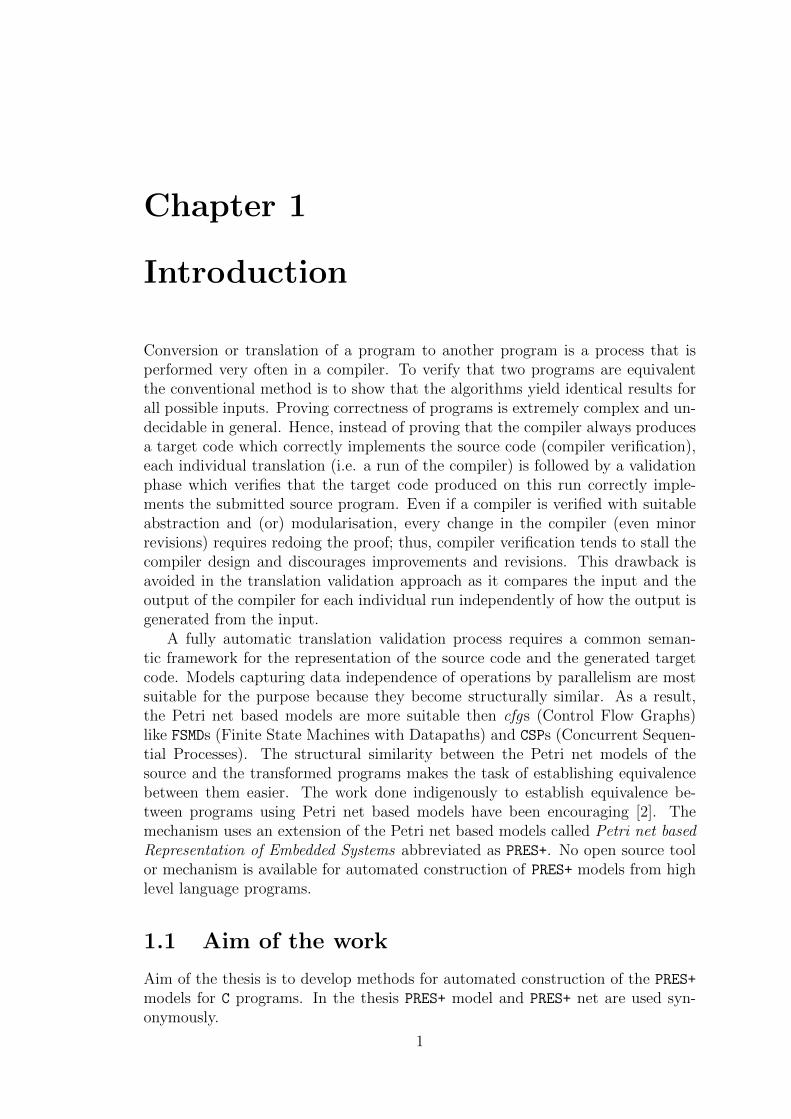
Conversion or translation of a program to another program is a process that isperformed very often in a compiler. To verify that two programs are equivalentthe conventional method is to show that the algorithms yield identical results forall possible inputs. Proving correctness of programs is extremely complex and un-decidable in general. Hence, instead of proving that the compiler always producesa target code which correctly implements the source code (compiler verification),each individual translation (i.e. a run of the compiler) is followed by a validationphase which verifies that the target code produced on this run correctly imple-ments the submitted source program. Even if a compiler is verified with suitableabstraction and (or) modularisation, every change in the compiler (even minorrevisions) requires redoing the proof; thus, compiler verification tends to stall thecompiler design and discourages improvements and revisions. This drawback isavoided in the translation validation approach as it compares the input and theoutput of the compiler for each individual run independently of how the output isgenerated from the input.
A fully automatic translation validation process requires a common seman-tic framework for the representation of the source code and the generated targetcode. Models capturing data independence of operations by parallelism are mostsuitable for the purpose because they become structurally similar. As a result,the Petri net based models are more suitable then cfgs (Control Flow Graphs)like FSMDs (Finite State Machines with Datapaths) and CSPs (Concurrent Sequen-tial Processes). The structural similarity between the Petri net models of thesource and the transformed programs makes the task of establishing equivalencebetween them easier. The work done indigenously to establish equivalence be-tween programs using Petri net based models have been encouraging [2]. Themechanism uses an extension of the Petri net based models called Petri net basedRepresentation of Embedded Systems abbreviated as PRES+. No open source toolor mechanism is available for automated construction of PRES+ models from highlevel language programs.
1.1 Aim of the work
Aim of the thesis is to develop methods for automated construction of the PRES+
models for C programs. In the thesis PRES+ model and PRES+ net are used syn-onymously.
1

1.2 Organization of the thesis
The mechanism for construction of the PRES+ model for a C program is explainedin the chapter 3. The explanation covers the data structures used for representingthe input C programs and the PRES+ models, the mechanism for constructing PRES+
for programs without loops and arrays, enhancement of the mechanism to handleloops and arrays and finally, the various optimizations performed on the PRES+
in that order. In chapter 4 a summary of the experimental results is providedfollowed by conclusion and future work in chapter 5. The algorithms explained inthe chapter 3 are summarized in the appendix A
2

Chapter 2
PRES+ model
In this chapter first a definition of the PRES+ (Petri net based Representation ofEmbedded Systems) model is provided. Next, an example of a PRES+ model isgiven.
2.1 Definition of PRES+ net
A PRES+ net is an eight tuple N = < P, T, I, O, inP, outP, V, fpv >, wherethe members are defined as follows. The set P is a finite non-empty set of places.A place p is capable of holding a token having a value vp of any data type. T is afinite non-empty set of transitions. A transition represents a function. I ⊆ P × Tis a finite non-empty set of input edges which define the flow relation from placesto transitions; a place p is said to be an input place of a transition t if (p, t) ∈ I.The relation O ⊆ T × P is a finite non-empty set of output edges which definethe flow relation from transitions to places; a place p is said to be an output placeof a transition t if (t, p) ∈ O. A place p ∈ P is said to be an in-port if and onlyif (t, p) /∈ O, for all t ∈ T . Likewise, a place p ∈ P is said to be an out-portif and only if (p, t) /∈ I, for all t ∈ T . V is the set of variables used in thePRES+ and fpv is a relation capturing the association of the places of the PRES+
with variables. A transition can have a guard condition associated with it s.t.
the transition is executed only if its guard condition is evaluated to True. Eachtransition operates on input tokens and produces zero or more output tokens.
2.2 An example of PRES+ model
Figure 2.1(A) and (B) show a C program and the corresponding control flow graph(cfg). The program contains one if-else statement and accordingly the cfgcontains four basic blocks. The corresponding PRES+ model is shown in the figure2.2. The PRES+ model has two input places namely, p1 and p2. The transitions t1and t2 are identity transitions and forward the token present in the first (zero-th)pre-place. The condition c in the if clause is captured using guarded transitions t5to t8. The transitions t5 and t6 represent the condition c being true and transitionst7 and t8 correspond to the negation of the condition c being true. You may notethat the transition t8 has no post-place as it serves the purpose of removing tokensin the places p9 and p10 when the negation of the condition c (i.e. the condition
3
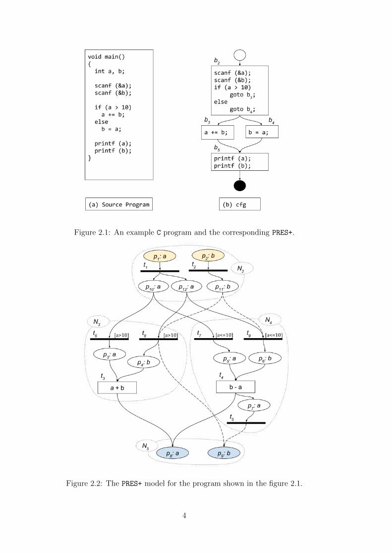
Figure 2.1: An example C program and the corresponding PRES+.
Figure 2.2: The PRES+ model for the program shown in the figure 2.1.
4

a ≤ 10) is true. If the condition c is true, then the transition t3 is executed.Otherwise, the transition t4 is executed. Eventually, the output is produced in theoutput tokens are produced in the places p6 and p7.
In the given and the following examples in the thesis, light yellow and lightblue color is used for input and output places of the PRES+ respectively; uncolored(white) places represent intermediate places in the PRES+. Dark black transitionsare identity transitions, forwarding the token in the the first pre-place. The tran-sitions having an expression associated with them are represented as rectangularboxes with the associated expression specified inside the box. The guard conditionassociated with a transition is written in square brackets ([]).
5

6

Chapter 3
Implementation
The block diagram for the construction of a PRES+ net is shown in figure 3.1. Theinput to the whole module is a C program and the output is the correspondingPRES+ net in a text file; the specifications of the input and the output files aregiven in the sections 3.1 and 3.2 respectively.
Figure 3.1: PRES+ construction block diagram
From a given C file first the corresponding control flow graph (cfg) is obtainedusing the -fdump-tree-cfg flag of the gcc. A cfg consists of three-address codewith basic block boundaries and is written into a text (.cfg) file by the gcc. Thecfg file is first parsed using Bison and Flex to obtain a symbol table and an arrayof basic blocks; the two data structures are explained in the section 3.3.
The given PRES+ construction methodology is able to construct PRES+ modelsfor programs containing loops and arrays. The mechanism for constructing asubnet corresponding to a basic block is explained in section 3.5.1 followed by themechanism for attaching the subnets to obtain the overall PRES+ in the section
7
3.5.2. To start with, the discussion is restricted to the simple cases of basic blocksinvolving only assignment and conditional statements without any loops. Thesubnet construction and attach mechanism is enhanced for programs involvingloops and arrays in sections 3.6 and 3.7 respectively.
The model construction mechanism consists in constructing first the PRES+models for all the basic blocks in isolation; accordingly, they appear as discon-nected sub-graphs, referred to as subnets; subsequently, they are attached to eachother to obtain the entire digraph for the PRES+ model of the complete program.
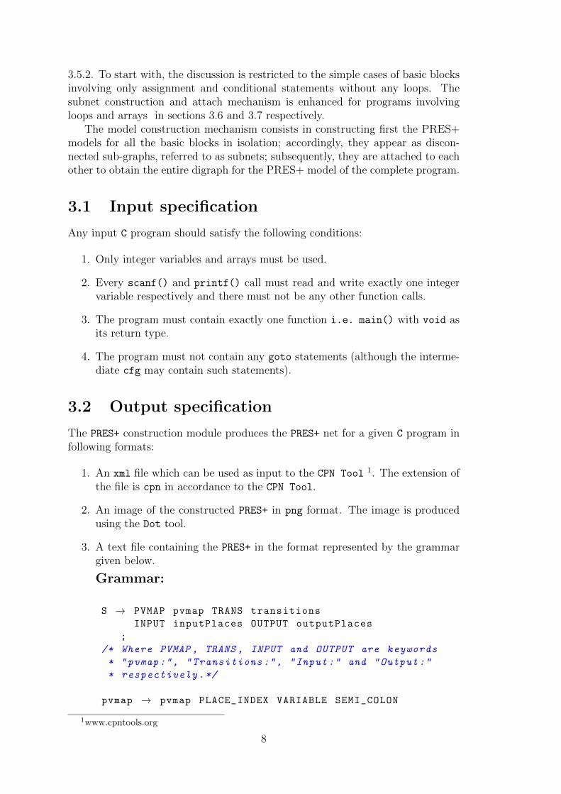
3.1 Input specification
Any input C program should satisfy the following conditions:
1. Only integer variables and arrays must be used.
2. Every scanf() and printf() call must read and write exactly one integervariable respectively and there must not be any other function calls.
3. The program must contain exactly one function i.e. main() with void asits return type.
4. The program must not contain any goto statements (although the interme-diate cfg may contain such statements).
3.2 Output specification
The PRES+ construction module produces the PRES+ net for a given C program infollowing formats:
1. An xml file which can be used as input to the CPN Tool 1. The extension ofthe file is cpn in accordance to the CPN Tool.
2. An image of the constructed PRES+ in png format. The image is producedusing the Dot tool.
3. A text file containing the PRES+ in the format represented by the grammargiven below.
Grammar:
S → PVMAP pvmap TRANS transitions
INPUT inputPlaces OUTPUT outputPlaces
;
/* Where PVMAP , TRANS , INPUT and OUTPUT are keywords
* "pvmap:", "Transitions :", "Input :" and "Output :"
* respectively.*/
pvmap → pvmap PLACE_INDEX VARIABLE SEMI_COLON
1www.cpntools.org
8

| PLACE_INDEX VARIABLE SEMI_COLON
;
/* Where PLACE_INDEX , VARIABLE and SEMI_COLON are an
* integer (id of the place), a string (name of the
* variable) and the character ‘;’ respectively.*/
transition → transition OP_CUR_BR
TRANS_INDEX SEMI_COLON
EXPR SEMI_COLON
GUARD SEMI_COLON
PRIORITY SEMI_COLON
preset SEMI_COLON
postset SEMI_COLON
CL_CUR_BR
| OP_CUR_BR
TRANS_INDEX SEMI_COLON
EXPR SEMI_COLON
GUARD SEMI_COLON
PRIORITY SEMI_COLON
preset SEMI_COLON
postset SEMI_COLON
CL_CUR_BR
;
/* OP_CUR_BR and CL_CUR_BR are ‘{’ and ‘}’ respectively
.
* TRANS_INDEX is an integer (id of the transition).
* EXPR and GUARD are the transition function and the
* guard associated to the transition respectively;
* PRIORITY is either ‘‘HIGH ’’ or ‘‘NORMAL ’’;
* needed by the model constructor for simulation in
* the CPN Tool as explained later. */
preset → preset PLACE_INDEX COMMA
| PLACE_INDEX SEMI_COLON
;
/* Where COMMA is ‘,’.*/
postset → postset PLACE_INDEX COMMA
| PLACE_INDEX SEMI_COLON
;
inputPlaces → inputPlaces PLACE_INDEX COMMA
| PLACE_INDEX SEMI_COLON
;
outputPlaces → outputPlaces PLACE_INDEX COMMA
| PLACE_INDEX SEMI_COLON
;
Grammar 3.1: Grammar for the output text file containing a PRES+ net
9
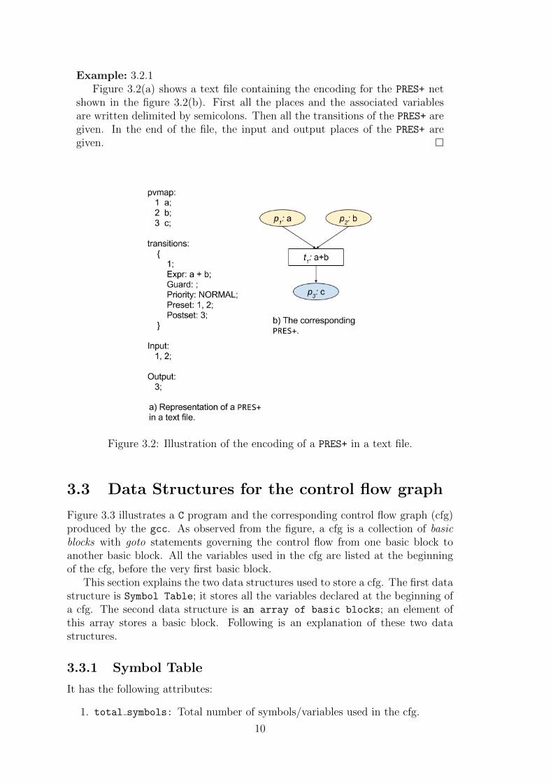
Example: 3.2.1Figure 3.2(a) shows a text file containing the encoding for the PRES+ net
shown in the figure 3.2(b). First all the places and the associated variablesare written delimited by semicolons. Then all the transitions of the PRES+ aregiven. In the end of the file, the input and output places of the PRES+ aregiven. �
Figure 3.2: Illustration of the encoding of a PRES+ in a text file.
3.3 Data Structures for the control flow graph
Figure 3.3 illustrates a C program and the corresponding control flow graph (cfg)produced by the gcc. As observed from the figure, a cfg is a collection of basicblocks with goto statements governing the control flow from one basic block toanother basic block. All the variables used in the cfg are listed at the beginningof the cfg, before the very first basic block.
This section explains the two data structures used to store a cfg. The first datastructure is Symbol Table; it stores all the variables declared at the beginning ofa cfg. The second data structure is an array of basic blocks; an element ofthis array stores a basic block. Following is an explanation of these two datastructures.
3.3.1 Symbol Table
It has the following attributes:
1. total symbols: Total number of symbols/variables used in the cfg.
10

Figure 3.3: A C program and the corresponding cfg.
2. symbols array[MAX VARIABLES] An array of size MAX VARIABLES where eachelement contains:
• var name: Name of the variable as a string.
• def: A bit vector of size MAX STATEMENTs (maximum statements in acfg) in which ith bit is set iff the statement with unique index (explainedin section 3.6.6) i defines the variable. This bit vector is used in livevariable analysis as explained in section 3.6.4.
• dimension: An integer to store the dimension of an array, if the symbolrepresents an array. Otherwise, it is assigned −1 to indicate that thesymbol does not represent an array.
3.3.2 BB array (Array of basic blocks)
It has the following attributes:
1. total BBs: Total number of basic blocks stored in the basic blocks array.
2. BB[MAX BBs]: An array of size MAX BBs in which each element stores a basicblock. This array is of type Basic block. Description of the Basic block
data structure follows.
3.3.3 Basic block
This data structure represents the contents of a basic block and has the followingattributes:
1. type: Type of a basic block i.e. NORMAL, CONDITIONAL or LAST.
11

Figure 3.4: A C program (a) and the corresponding cfg (b).
NORMAL, CONDITIONAL and LAST are basic blocks with one, two and zerosuccessor(s) respectively. A basic block can have at most one if-then-elsestatement and that too as the last statement. As a result a basic blockcan have either zero, one or two successor(s).
Example: 3.3.1
The cfg for the program shown in figure 3.4(a) is shown in the figure3.4(b). In the cfg the basic blocks b2 and b3 have type Conditional;Basic blocks b4 and b5 have types Normal and Last respectively. �
2. pred count: Number of the predecessors of a basic block. For a programhaving n basic blocks, the number of predecessors can be anything in therange [0, n− 1]; the first basic block of a program has zero predecessors.
Example: 3.3.2
Figure 3.4(b) is the cfg corresponding to the program shown in the figure3.4(a). In the cfg the basic block b5 has three (n− 1) predecessors. �
3. predecessors[MAX PREDECESSORs]: An integer array of size MAX PREDECESSORs
to store the indices of the predecessors of a basic block.
4. stm count: Number of statements in a basic block, excluding the if-else
statement in CONDITIONAL basic blocks.
5. statements[MAX STATEMENTs]: An array of type Statement and size MAX STATEMENTs
to store the statements of a basic block. The Statement data structure isexplained in the section 3.3.4.
12

6. cond: A pointer to the expression tree of the expression in the if-else
statement of a conditional basic block. Expression tress are used to storeexpressions as explained in section 3.3.5.
7. visited: A boolean flag for DFS and (or) BFS, as and when needed.
8. true successor: Index of the unique successor for a NORMAL basic blockand true successor for a CONDITIONAL basic block. -1 for the LAST basicblock.
9. false successor: Index of the false successor for a CONDITIONAL basicblock and -1 for NORMAL and LAST basic blocks.
10. live in: A bit vector to store the variables live at the beginning of abasic block. This bit vector is obtained from live variable analysis (lva) asexplained in section 3.6.4. The need for lva is established in the section3.6.2. ith bit of this bit vector is set iff the variable at index i in the symboltable is live at the beginning of a basic block.
11. live out: A bit vector similar to live in but stores the variables live atthe end of a basic block.
12. rd in: A bit vector to store the reaching definitions at the beginning ofa basic block. The role of the reaching definitions is explained in section3.6.3 and the mechanism itself is explained in section 3.6.6. ith bit of this bitvector is set iff the statement with unique index (explained in section 3.6.6)i is a reaching definition at the beginning of a basic block.
13. rd out: A bit vector similar to rd inbut stores the reaching definition at theend of a basic block.
3.3.4 Statement
This data structure is used to store the attributes of a statement in a basic block.Its attributes are:
1. type: Type of a statement i.e. scanf, printf, Asngid, Asgnunary orAsgnbinary
scanf: is a statement corresponding to a scanf() function call.
printf: is a statement corresponding to a printf() function call.
Asgnid: An assignment statement which assigns the value of a variable toanother variable without any operation, for e.g. a = b;.
Asgnunary: An assignment statement which has a literal or a unary operatorassociated to a variable on its right hand side (RHS). Examples of suchstatements are a = −b;, a = 10; etc.
Asgnbinary: An assignment statement with an expression involving a binaryoperator on its RHS. Examples of such statements are a = b + c;,a = b− 10; etc.
13

2. var: Index (to the Symbol Table) of the variable defined in the scanf andthe assignment statements. Index of the output variable for the printf
statements.
3. expr: Pointer to the expression tree on the RHS of an assignment state-ment. NULL for the scanf and printf statements.
3.3.5 Expression Tree
It is a binary tree used to store the expression on the RHS of an assignmentstatement. Expression trees for various statements are shown in the figure 3.5.The attributes of a node of an expression tree are:
Figure 3.5: Expression trees for various types of statements.
1. type: Type of a node i.e. Binary operator, Unary operator, Variable
or Literal.
Binary operator: Root node of an expression tree representing a binaryoperator. Left and right operands are stored in the left and the rightchild respectively.
Unary operator: Root node of an expression tree representing a unaryoperator. Left operand is stored in the left child and the right child isNULL.
Variable: A node containing index (to the Symbol Table) of a variable.
Literal: A node containing value of an integer literal, since only integersare allowed.
2. identifier: Depending on the type field, this attribute specifies an op-erator ∈ {+,−, ∗, /,%, <,≤, >,≥,=,==} (for type Binary operator andUnary operator), index of a variable (for type Variable) or a constantvalue (for type Literal).
3. left: Pointer to the node corresponding to the left operand.
4. right: Pointer to the node corresponding to the right operand.
14

3.4 Data Structures for the PRES+ model
In this section the data structures used to represent the overall PRES+ model andthe PRES+ model corresponding to each basic block are explained.
3.4.1 Pres Plus
It is the data structure used to store the overall PRES+ net. Its various attributesare:
1. places count: An integer to store the total number of places in the PRES+.
2. places[MAX PLACEs]: An array of type Place and size MAX PLACEs used tostore the places of the PRES+. The data type Place is explained subsequently.
3. trans count: An integer to store the total number of transitions in thePRES+.
4. trans[MAX TRANSITIONs]: An array of type Transition and size MAX TRANSITIONs
used to store the transitions of the PRES+. The data type Transition is ex-plained subsequently.
5. input places count: An integer to store the total number of the inputplaces of the PRES+.
6. input places[MAX PLACEs]: An integer array of size MAX PLACEs to storethe indices to the array places[] of the input places of the PRES+.
7. output places count: An integer to store the total number of the outputplaces of the PRES+.
8. output places[MAX PLACEs]: An integer array of size MAX PLACEs to storethe indices to the array places[] of the output places of the PRES+.
3.4.2 Place
This data structure is used to represent a place in the PRES+. Its various attributesare:
1. type: The type of a place - one of {Input port, Output port, Var,
Dummy}
Input port is a place which takes input tokens for a PRES+.
Output port is a place which provides output tokens of a PRES+.
Var is an intermediate place which provides flow of tokens between transi-tions.
Dummy is also an intermediate place providing flow of tokens between transi-tions. These places are used for synchronization and have no variablesassociated with them.
Input port, Output port and Var, all have a variable associated withthem.
15

2. var: If the type is Input port, Output port or Var, then it is the index tothe Symbol Table of the variable associated with the place; if the place typeis Dummy, then it is −1.
3. preset count: Stores the total number of pre-transitions of a place.
4. preset[MAX PRESET PLACE]: Stores the indices of the pre-transitions of theplace to the array transitions[] of all transitions of the PRES+.
5. postset count: Stores the total number of post-transitions of a place.
6. preset[MAX POSTSET PLACE]: Stores the indices of the post-transitions ofthe place to the array transitions[] of all transitions of the PRES+.
3.4.3 Transition
This data structure is used to represent a transition in the PRES+. It has thefollowing attributes:
1. type: Type of a transition - one of {Identity, Expression}.
Identity transitions represent the variable copy function i.e. a = b.They forward the token associated with the first pre-place (with indexvalue 0). They do not have any expression associated with them.
Expression transitions perform some operation on the input tokens beforeproducing output and have an expression tree associated with them.The transition corresponding to the statement a = b + c; belongs tothis category.
2. expr: Pointer to the expression tree associated with the Expression tran-sitions. NULL for the Identity transitions.
3. guard: If the transition has a guard condition associated with it, then it isa pointer to the expression tree representing the guard condition associatedwith the transition; if the transition does not has a guard condition, then itis NULL.
4. preset count: Stores the number of pre-places of the transition.
5. preset[MAX PRESET TRANS]: Stores the indices of the pre-places of the tran-sition to the array places[] of all the places of the PRES+.
6. postset count: Stores the number of post-places of the transition.
7. postset[MAX POSTSET TRANS]: Stores the indices of the post-places of thetransition to the array places[] of all the places of the PRES+.
16

3.4.4 Subnets[MAX BBs]
An array to identify the PRES+ subnet corresponding to a basic block in the overallPRES+ net. An element of the array, Subnet[i], has the following attributes andidentifies the subnet corresponding to the ith basic block in the basic blocks array.
1. places count: Number of places of the ith subnet.
2. places[MAX PLACEs]: Stores the indices of the places of the ith subnet tothe array places[] of all the places of the overall PRES+.
3. transitions count: Number of transitions of the ith subnet.
4. transitions[MAX TRANSITIONs]: Stores the indices of the transitions of theith subnet to the array transitions[] of all the transitions of the overallPRES+.
5. input places[MAX PLACEs]: Stores the indices of the the local input placesof the ith subnet to the array places[] of all the places of the overall PRES+.
6. input places count: Number of the input places in the array input places[]
described above.
7. ldt[MAX VARIABLEs]: An array to store the latest defining transitions inthe ith subnet of the variables of the variables occurring in the subnet. Theentry ldt[v] is the transition in the ith subnet which provides the latesttoken for the variable v. If a variable v is not defined in the ith subnet thenthe ldt[v] is −1 and if v is defined twice then the ldt[v] is the transitiongenerating the latest token.
8. maximum transition: An integer to store the maximum transition of the ith
subnet. The role of the maximum transitions is explained in section 3.6.2.
9. maximum tr sync pl: An integer to store the index of the place to the arrayplaces[] in the overall PRES+ used to synchronize the maximum transitionof the ith subnet with that of its predecessors. The type of this place isDummy.
10. maximal trans count: Stores the number of maximal transitions of a sub-net.
11. maximal trans[MAX TRANSITIONs]: Stores the indices of the maximal tran-sitions of the ith subnet to the array transitions[] of all the transitions ofthe overall PRES+. The role of maximal transitions is explained in section3.6.2.
12. loop: A boolean variable having a value True if the ith subnet belongs to aloop body; False otherwise.
13. interface variables[MAX VARIABLEs]: An integer array of size MAX VARIABLEs;it stores the indices of places to the array places[] in the overall PRES+.Interface places are Dummy places used in successors of Conditional subnetsin loop bodies to capture the conditional execution of such subnets; they arefurther explained in the section 3.6.2. An element v of this array is −1 ifthere exists no interface place in the ith subnet for the variable v.
17

3.5 Construction of PRES+ for programs without
loops
In this section the construction of PRES+ models for C programs containing onlyinput (scanf), output (printf), assignment and if-else statements i.e., forprograms free from loops and arrays is explained. The model construction mech-anism consists of constructing first the PRES+ models for all the basic blocks inisolation; accordingly, they appear as disconnected sub-graphs, referred to as sub-nets; subsequently, they are attached to each other to obtain the entire digraphfor the PRES+ model of the complete program.
3.5.1 Construction of a PRES+ subnet
This section explains the construction of a PRES+ subnet for a basic block. Theapproach is to construct the respective places and transitions for each statementof the basic block in the overall PRES+ itself. The statements of the basic block areprocessed in the order of their appearance in the basic block and the constructedplaces and transitions are then attached to the PRES+ subnet corresponding to thepreceding statements of the basic block but not to the overall PRES+ net.
Construction of the PRES+ for a basic block consists of constructing the PRES+
subnet for each statement in it followed by its attachment to the already con-structed PRES+ subnet constructed for the preceding statements in the basic block.The given procedure repeated for all the statements of a basic block in the orderof their occurrence constructs the PRES+ subnet for a basic block.
Note that although processed sequentially, the step of attaching the newlycreated PRES+ subnet ensures that sequentiality is incorporated only for read afterwrite (RAW) dependencies; thus, even for a sequence of assignment statements thecorresponding subnet may have disconnected components depicting parallelism(due to dependence) among the components and sequentiality only inside eachcomponent. The inputs and outputs of this module are:
Inputs:
1. bba: A pointer to the array of basic blocks. Recall that BB Array is astructure containing the array of basic blocks along with a count of the totalnumber of basic blocks in the cfg (control flow graph).
2. st: A pointer to the symbol table.
3. PP: A pointer to the structure Pres Plus representing the overall PRES+.
4. Subnets[]: A pointer to the subnets array.
5. k: Index of the present basic block for which the PRES+ subnet should beconstructed to the basic blocks array.
Outputs:
1. The overall PRES+ net PP is modified to contain the PRES+ subnet corre-sponding to the given basic block.
18

2. The kth element of the Subnets[] array is modified to identify the subnetcorresponding to the kth basic block in the overall PRES+ net PP.
Construction of the PRES+ subnet for each statement depends on the type ofthe statement and is explained below.
Figure 3.6: PRES+ for ascanf statement Figure 3.7: PRES+ of a printf statement
scanf statement
For a scanf statement reading a variable v two places p and p′ are constructed andassigned the types Input port and Dummy respectively. The place p is assignedv as the associated variable and added to the input places array of the overallPRES+ PP; the place p′ is added to the input places array of the kth subnet(Subnets[k]). The purpose of the Dummy place p′ is to provide synchronization ifthe scanf statement belongs to an if-then-else clause.
An identity transition t is constructed and attached to the places p and p′
as a post-transition in that order; t is set as the latest defining transition (ldt)of the variable v in Subnets[k]. The places p and p′ are added to the places
array of the Subnets[k]; the transition t is added to the transitions array ofSubnets[k]. The PRES+ for a scanf statement is illustrated in figure 3.6. Itmay be noted that output places of any transition are constructed only when thecorresponding value produced by the transition is used subsequently.
printf statement
For a printf statement printing a variable v a place p is constructed, assignedthe type Output port and v as the associated variable. The place p is added tothe output places array of the overall PRES+ PP. If in Subnets[k] an ldt existsfor the printed variable then p is attached to the ldt as a post-place, as shown infigure 3.7(A); otherwise p is added to the input places array of the Subnets[k]
as shown in figure 3.7(B).
Asgnid statement
These are statements of type vl = vr, i.e. the value of one variable is assignedto another variable without any operation. If an ldt exists for vr in Subnets[k],the variable on the right hand side, then the ldt[vr] is set as the ldt for vl alsowhere vl is the variable on the LHS, as shown in figure 3.8(A).
Otherwise, an ldt does not exist for vr in Subnets[k]. A place p and anidentity transition t are constructed. The variable vr is variable associated
19
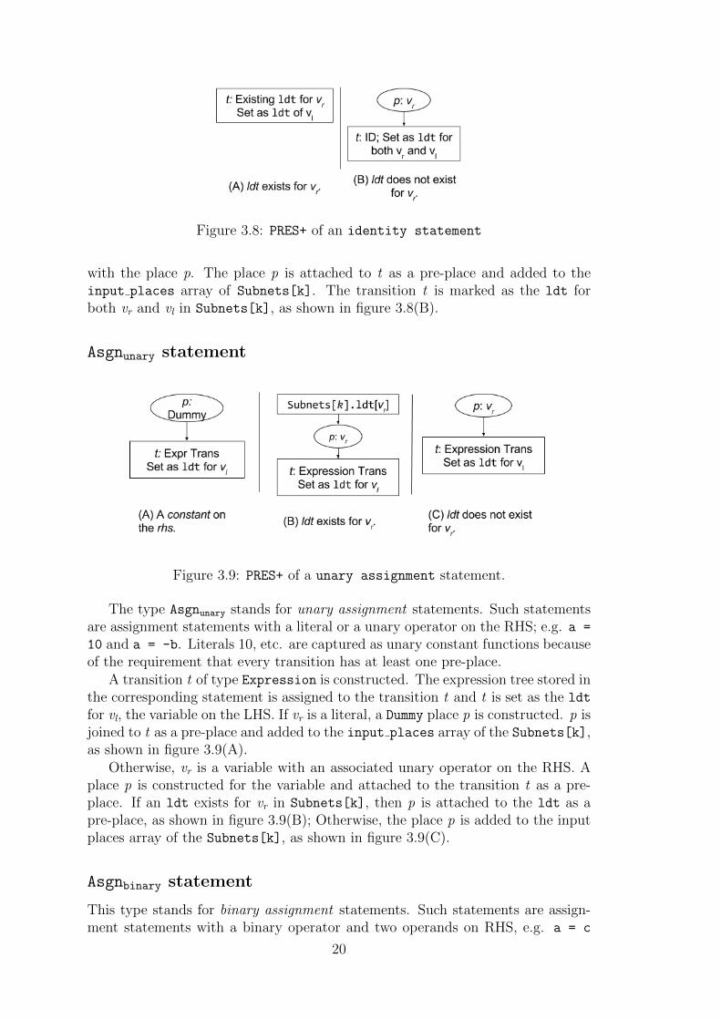
Figure 3.8: PRES+ of an identity statement
with the place p. The place p is attached to t as a pre-place and added to theinput places array of Subnets[k]. The transition t is marked as the ldt forboth vr and vl in Subnets[k], as shown in figure 3.8(B).
Asgnunary statement
Figure 3.9: PRES+ of a unary assignment statement.
The type Asgnunary stands for unary assignment statements. Such statementsare assignment statements with a literal or a unary operator on the RHS; e.g. a =
10 and a = -b. Literals 10, etc. are captured as unary constant functions becauseof the requirement that every transition has at least one pre-place.
A transition t of type Expression is constructed. The expression tree stored inthe corresponding statement is assigned to the transition t and t is set as the ldt
for vl, the variable on the LHS. If vr is a literal, a Dummy place p is constructed. p isjoined to t as a pre-place and added to the input places array of the Subnets[k],as shown in figure 3.9(A).
Otherwise, vr is a variable with an associated unary operator on the RHS. Aplace p is constructed for the variable and attached to the transition t as a pre-place. If an ldt exists for vr in Subnets[k], then p is attached to the ldt as apre-place, as shown in figure 3.9(B); Otherwise, the place p is added to the inputplaces array of the Subnets[k], as shown in figure 3.9(C).
Asgnbinary statement
This type stands for binary assignment statements. Such statements are assign-ment statements with a binary operator and two operands on RHS, e.g. a = c
20

Figure 3.10: PRES+ of binary assignment statement. The pre-places of the tran-sition t are attached to their ldts as post-places, if the ldts exist.
- b and a = 10 + 30. The operands can be any combination of variables andliterals. If both the operands are literals, a dummy place p is constructed andadded to the input places array of the Subnets[k]. The construction of thetransition for the statement is explained subsequently.
Otherwise, at least one of the operands on the RHS is a variable. Places areconstructed for the operands which are variables and the ones having an ldt inSubnets[k] are joined to the ldt as post-places; the remaining places (not havingan ldt in Subnets[k]) are added to the input places array of the Subnets[k].
A transition t of type Expression is constructed with the expression treestored in the statement as the expression of t. The places constructed for thestatement are joined to t as pre-places and the transition t is set as the ldt forthe variable vl, the variable on the LHS, as shown in figure 3.10.
if-else statement
The if-else statement of a Conditional basic block is always the last statementof the basic block and is processed while attaching the corresponding subnet tothe two successors. Therefore, the procedure for handling if-else statements isexplained along with the explanation of the methodology for attaching subnets.
The mechanism is summarized in the algorithm 1 (page 56).
3.5.2 Attach PRES+ subnets
In this section the procedure of attaching the individual subnets correspondingto the basic blocks to obtain an overall PRES+ net is explained. To attach thesubnets, a depth first traversal (dfs traversal) is performed on the cfg and thesubnets are attached to their successors while backtracking, as illustrated in thefollowing example.
Example: 3.5.1With respect to the cfg shown in the figure 3.11, the dfs traversal for
attach begins with the subnet N1 which, being a Conditional subnet, hastwo successors namely, N2 and N3; the true successor N2 is traversed firstfrom which its unique successor N4 is visited. Since N4 does not have any
21

Figure 3.11: A cfg to illustrate the dfs traversal for attach.
successor, the traversal backtracks to N2 whereupon the latter is attached toits successor N4. Let this attached subnet be referred to as N2 · N4 wherethe · (dot) operation captures the predecessor-successor relationship of thesubnets involved in the attachment step. After the attachment, the traversalbacktracks from N2 to N1. The attached subnet N2 ·N4 is not attached to N1
immediately because another successor N3 of N1 has not yet been traversed;the dfs then visits N3, the untraversed successor of N1. From the subnet N3, thedfs visits its unique successor N4 but backtracks immediately as N4 has alreadybeen traversed. Now N3 is attached to N2 · N4 and the traversal backtracksto N1. It may be noted that while attaching N3 to N2 · N4, the subnet N3
virtually gets attached to its successor N4 and not to N2; this fact is reflectedin depicting the attached subnet as (N2|N3) ·N4 underlining the feature thatN4 is the successor to both N2 and N3 and there is no predecessor-successorrelation between N2 and N3. At the subnet N1, since both of its successorshave been traversed, N1 is attached to them (depicted as N1 · (N2|N3) · N4)and the dfs traversal terminates. �
Recall that a basic block (and its corresponding subnet) can have either zero,one or two successors and are accordingly assigned one of the three types namely,Last, Normal and Conditional; the attachment procedure of a subnet to itssuccessors is described under these three categories of the subnets. In the followingsections, the attributes of a basic block such as type, successor, predecessor, etc.,and those of its subnet are used synonymously.
During the dfs traversal for attaching subnets, no processing is done when thesubnets of type Last are visited since the attachment step attaches a subnet withits successors and such subnets have no successors. For the other two types ofsubnets, the corresponding steps for attaching the successors are explained in thefollowing subsections where the attachment steps are explained using the examplegiven below.
Example: 3.5.2Figures 3.12(a), (b) and (c) show the source program, the control flow
graph of the basic blocks and the PRES+ subnets corresponding to the indi-vidual basic blocks, respectively. There is one Conditional subnet N2, twoNormal subnets, N3 and N4 and one Last subnet N5. In the following sections,
22

Figure 3.12: An example to illustrate the attaching of subnets
first the attachment of the subnet N3 and N4 to their unique successor N5 andthen the attachment of the subnet N2 to its successors are explained. �
Attaching Normal subnet
To attach a Normal subnet Nnorm to its unique successor Nsucc, each input placepin of Nsucc is attached to the subnet Nnorm based on the type of the place pin asdescribed below.
pin is an Input port
Recall (from section 3.5.1) that the places of the type Input port are constructedonly for scanf statements and they take input tokens for the PRES+. Such placesare never added to the local input places array of a subnet; hence, this case doesnot arise.
23
pin is of type Var or is an Output port
Let v be the variable associated with the place pin. If there exists an ldt (latestdefining transition) for v in the subnet Nnorm, then pin is attached as a post-placeto the transition. Otherwise, the place pin is added to the input places array ofthe subnet Nnorm.
pin is of type Dummy
As mentioned while discussing the construction methodology given in the section3.5.1, Dummy places are constructed as pre-places for transitions corresponding toconstant functions. Such transitions have no data dependence on any other transi-tion though they may have a control dependence. However, in the present context,since the place pin is being attached to a Normal subnet, there is no conditionalcontrol dependence. Hence, the place pin is added to the input places array ofthe subnet Nnorm.
Example: 3.5.3In continuation of the example 3.5.2, the present example illustrates the
attachment procedure of the Normal subnets N3 and N4 to their unique succes-sor N5; the resultant PRES+ is shown in the figure 3.13. To attach the Normal
subnet N3 to its unique successor N5, the input places p7 and p8 of N5 areconsidered. The variable a associated with the place p7 has an ldt t3 in thesubnet N3; hence, p7 is attached as a post-place to t3. Similarly, the place p8
has b as the associated variable which does not have any ldt in N3; as a resultthe place p8 is added to the input places array of the subnet N3.
The subnet N4 is attached to its unique successor N5 using a similarmethod. The input places p7 and p8 of N5 are attached as post-places totheir common ldt t4. �
Attaching Conditional subnet
To attach a Conditional subnet Ncond to its two successors — the true successorNt and the false successor Nf — each input place pin of the two successors needsto be attached to the subnet Ncond. The steps needed for the purpose are firstdescribed using two examples and then a generalized procedure is given.
Example: 3.5.4In continuation of the example 3.5.2, the present example illustrates the
attachment of the Conditional subnet N2 to its two successors N3 and N4; theresultant PRES+ obtained after attachment is shown in figure 3.14. In order toattach the conditional subnet N2 to its successors, the input places of the suc-cessors are attached to N2 and are processed based on the variable associatedwith them. In the concerned example, the set V of variables associated withthe input places of the two successors consists of the variables a and b. Toattach the successors N3 and N4 to N2, each variable in the set V is processedone by one.
Considering the variable a first, two identity transitions t5 and t6 are con-
24

Figure 3.13: Resultant PRES+ after attaching the Normal subnets to the successorsfor the PRES+ shown in the figure 3.12(c).
structed. Recall that in section 3.5.1, the conditional expression c associatedwith the if clause in the subnet N2 (or more precisely, in the correspondingbasic block b2) was ignored. The conditional expression c and its negation ¬care assigned to the transitions t5 and t6 as the guards, respectively. The inputplace p3 of the true successor N3 and p5 of the false successor N4 having a asthe associated variable are attached as post-places to the transitions t5 andt6, respectively. A place p9 for the variable a is attached to the transitions t5and t6 as a common pre-place and as a post-place to the corresponding ldt t1of the variable a in the subnet N2. Since both transition function and guardcondition of the transitions t5 and t6 use only the variable a, no other pre-placeneeds to be constructed for the transitions.
For the other variable b in the set V , transitions t7 and t8 are constructedin a similar fashion as for the variable a. The input places p4 and p8 of thetrue successor and p6 of the false successor having b as the associated variableare attached as post-places to the transitions t7 and t8, respectively. A place
25
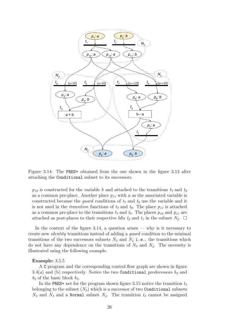
Figure 3.14: The PRES+ obtained from the one shown in the figure 3.13 afterattaching the Conditional subnet to its successors.
p10 is constructed for the variable b and attached to the transitions t7 and t8as a common pre-place. Another place p11 with a as the associated variable isconstructed because the guard conditions of t7 and t8 use the variable and itis not used in the transition functions of t7 and t8. The place p11 is attachedas a common pre-place to the transitions t7 and t8. The places p10 and p11 areattached as post-places to their respective ldts t2 and t1 in the subnet N2. �
In the context of the figure 3.14, a question arises — why is it necessary tocreate new identity transitions instead of adding a guard condition to the minimaltransitions of the two successors subnets N3 and N4 i.e., the transitions whichdo not have any dependence on the transitions of N3 and N4. The necessity isillustrated using the following example.
Example: 3.5.5A C program and the corresponding control flow graph are shown in figure
3.4(a) and (b) respectively. Notice the two Conditional predecessors b2 andb3 of the basic block b5.
In the PRES+ net for the program shown figure 3.15 notice the transition t3belonging to the subnet (N5) which is a successor of two Conditional subnetsN2 and N3 and a Normal subnet N4. The transition t3 cannot be assigned
26

Figure 3.15: PRES+ net for the program shown in the figure 3.4.
a guard because it will be executed always; the only factor that needs to begoverned is the transition which shall provide token to the pre-place p3 of thetransition t3. To properly route the token to the place p3, guarded transitionst4 and t6 are constructed and the three pre-transitions of p3 reflect the threepossible paths to reach the subnet N5 in the control flow graph. �
The method for attaching Conditional subnets
Figure 3.16: General structure of a Conditional subnet and its successors.
27
The attachment of the input places of the true (Nt) and the false (Nf) successorsof a Conditional subnet Ncond is governed by the variables associated with theinput places of Nt and Nf. Let v be the variable associated with some input placesof Nt (or Nf). Let P t
v and P fv be the set of the input places of the subnets Nt and
Nf respectively with v as the associated variable, as shown in figure 3.16.
If either of the sets P tv or P f
v is non-empty, then two identity transitions tt andtf are constructed with c and ¬c as the guard condition respectively, where c isthe condition in the if clause of the Conditional subnet (corresponding basicblock) Ncond. All the places in the sets P t
v and P fv are attached as post-places to
the transitions tt and tf, respectively.
A place p is constructed with v as the associated variable and attached as acommon pre-place to the transitions tt and tf. If an ldt exists for v in Ncond, then pis attached as a post-place to the ldt ; otherwise, p is added to the input places
array of the subnet Ncond.
For each variable v′ used in the condition c other than the variable v, a placep′ is constructed and attached as a common pre-place to the transitions tt and tf.The place p′ is attached to Ncond in a manner similar to the attachment of theplace p.
Dummy input places of the successors:The attachment procedure of the Dummy input places of Nt and Nf is similar tothat of the places with v as the associated variable with the difference being thatthe place p (as shown in figure 3.16) is not constructed. Places are constructedand processed for the variables used in the guard condition as described above.
3.6 Construction of PRES+ for programs contain-
ing loops
This section explains the enhancement of the model construction mechanism tohandle programs containing loops. The mechanism for detecting the subnets be-longing to a loop body is explained first, followed by the steps for programs con-taining loops without nesting. Next, the mechanism to extract parallelism betweena loop and the segments preceding and following it is explained; finally, the mech-anism to handle programs containing nested loops is presented.
3.6.1 Subnets belonging to a loop body
To detect if a subnet belongs to a loop body or not a boolean variable called loopis used. It maintained for each subnet and is initialized to false indicating that asubnet does not belong to any loop. The value of this variable is modified whilebacktracking in the dfs traversal as described below.
First for the subnets from which back edges emanate the variable loop is set astrue. For a Normal subnet Nn, if its successor belongs to a loop, then the subnetNn’s loop variable is also set to true. In case of a Conditional subnet which is nota loop header if the successors belong to a loop, then the subnet itself also belongs
28

to a loop. For a loop header subnet, it belongs to a loop if its false successor hasits loop variable set to true.
3.6.2 Loops without nesting
Let Nl be the subnet corresponding to a non-nested loop body, Nh be the subnetcorresponding to the loop header and Ne be the subnet corresponding to the basicblock which is reached through the loop exit; thus, Nl and Ne are the two suc-cessors of the conditional subnet Nh. The loop structures captured by the presentmechanism can be represented by the regular expression Nh(Nl)
∗Ne encompassingfor and while loops; do-while loops (with structures represented by the regularexpression NlNh(Nl)
∗Ne) are not encompassed.
Corresponding to a loop, a PRES+ subnet is constructed for the entire loop bodyand attached to the rest of the PRES+. Thus, it may be noted that while construct-ing Nl it is ensured that transitions having no dependence among themselves areexecuted in parallel. The subnet for a non-nested loop body is obtained using thesame mechanism described for programs containing no loops because a non-nestedloop body is essentially a sub-program without any loop. For loops, another impor-tant property is also to be ensured namely, prevention of simultaneous executionof different loop iterations. This property guides the steps for attaching varioussubnets to construct Nl and also while attaching Nl to Nh. First, the enhance-ment necessary in the construction of Nl corresponding to a loop body (over theprocess used for segments outside any loop); it also underlines the enhancementneeded in attaching Nl to Nh (over the process of attaching any conditional subnetto its successors) and is illustrated using the following example; the generalizedprocedure along with the rationale for various steps is then described.
Figure 3.17: Source code and the cfg of an example program containing a loop.
29

Figure 3.18: The PRES+ net consisting of unattached subnets corresponding to theprogram given in figure 3.17.
Example: 3.6.1Figure 3.17(A) and (B) show a C program containing a loop and the cor-
responding cfg, respectively. The PRES+ consisting of the unattached subnetsfor the basic blocks and the overall PRES+ are shown in the figures 3.18 and3.19, respectively.
Initially, all the subnets are marked as Not visited and the dfs traversalfor attaching the subnets begins with the subnet N2. The subnets N2, N4 andN3 are traversed in that order and are marked as Visiting. When the dfstraversal visits N4 again as a child of N3, the dfs backtracks because N4 is inVisiting state and a loop (a back edge) is detected designating N4 as theloop header and N3 as the loop body.
The subnet N3 is not only the true successor of the conditional subnet N4
but also is a loop body; hence, the construction cannot be considered to becomplete and ready for attachment with N4 and itself, unless it is ensured thatthe ith firing instance of all its transitions (corresponding to the ith iteration)precedes the (i + 1)th firing instance of any of its transition. To ensure suchstrict sequentiality between two iterations of N3 the end of a loop iterationis captured by a notion of maximum transition of the loop body. The loopbody, however, consists of multiple independent execution paths leading tomaximal transitions, a maximum transition, therefore, needs to be speciallyconstructed. In the concerned figure (3.19) the transition t4 is introduced as amaximum transition and all the maximal transitions (t2 and t3) of the subnetN3 are attached to t4 via Dummy places (p11 and p13). A Dummy place p18 is alsoconstructed for synchronizing the maximum transition of the subnet N4 withits predecessor N3.
With the execution of the maximum transition, an iteration of loop bodycompletes and the next iteration can be started. To start an iteration ofa loop tokens need to be provided in the input places of the loop header,which do not exist right now because the loop header gets its input places
30
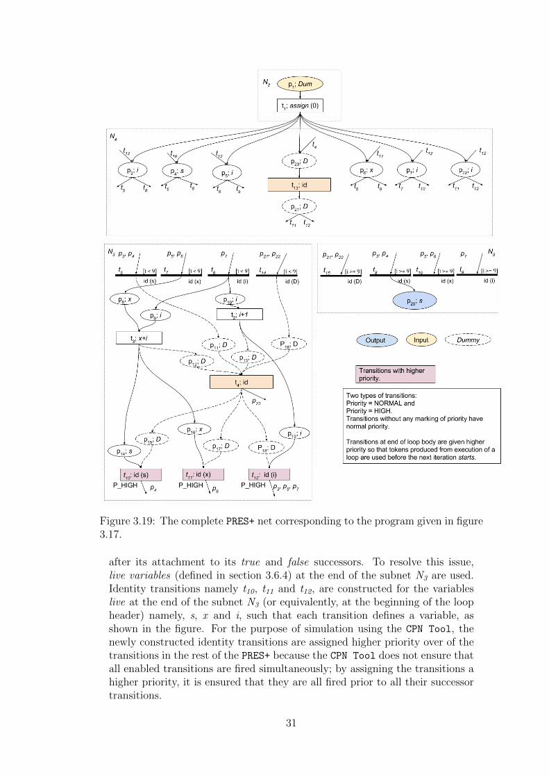
Figure 3.19: The complete PRES+ net corresponding to the program given in figure3.17.
after its attachment to its true and false successors. To resolve this issue,live variables (defined in section 3.6.4) at the end of the subnet N3 are used.Identity transitions namely t10, t11 and t12, are constructed for the variableslive at the end of the subnet N3 (or equivalently, at the beginning of the loopheader) namely, s, x and i, such that each transition defines a variable, asshown in the figure. For the purpose of simulation using the CPN Tool, thenewly constructed identity transitions are assigned higher priority over of thetransitions in the rest of the PRES+ because the CPN Tool does not ensure thatall enabled transitions are fired simultaneously; by assigning the transitions ahigher priority, it is ensured that they are all fired prior to all their successortransitions.
31

Figure 3.20: A subgraph of a cfg belonging to a loop body and the correspondingdisconnected PRES+ net of individual subnets.
For each of the transitions t10, t11 and t12, a pre-place associated withthe respective live variable and a Dummy place are constructed. The first setof pre-places (associated with the live variables) are the post-places of thecorresponding ldts in N3; the second set of Dummy pre-places are post-placesof the maximum transition t4. These transitions thus get attached to N3
and become the new set of maximal transitions providing values for the nextiteration of Nl or the loop exit subnet Ne. Accordingly, the transitions t10, t11and t12 are set as the ldts of the respective live variables.
After the above mentioned enhancement of N3, the dfs traversal backtracksfrom N3 to its predecessor N4; the attachment of the subnet N4 to its successorN3, however, is deferred as the the subnet N4 has an un-traversed successorN5; the dfs traversal then visits N5. Since the subnet N5 is of type Last, thedfs backtracks right away to the loop header subnet N4 again.
Having both its successors N3 and N5 traversed, the subnet N4 is now at-tached to its successors using the procedure described for attaching a Conditionalsubnet to its successors for programs without loops. In course of attachmentof N3 to N4, three new transitions are constructed for N3 namely, t5, t6 and t7.Among these, t5 has an empty post-set because the variable s is not live at thebeginning of N3 and hence is attached to the maximum transition t4 via theDummy place p11. A maximum transition t13 is also constructed for the loopheader N3. Transitions t14 and t15 are constructed for attaching the maximumtransitions of the subnets as shown in the figure. Since the loop header N3
32

itself does not belong to a loop body, the maximum transition synchronizationplace p23 is added to the input places array of the subnet.
Recall that the subnet N4 has so far remained empty. The construction ofthe input places in the subnet N4 comes from general attachment procedure ofa conditional subnet with its successors. Now that the loop header subnet N4
has been attached to its successors, it is attached to the loop body N3 fromwhich back edges lead to the loop header subnet N4. For this purpose, theprocedure for attaching a Normal subnet to its successors with a modificationthat the Dummy input places of N4 are attached as post-places to the maximumtransition of N3 is invoked on the subnet N3 is invoked on the subnet N3.
The dfs traversal then backtracks to the subnet N2 which is then attachedto its successor N4 following the usual procedure for attaching a Normal subnetto its successor completing the construction of the overall PRES+. �
Figure 3.21: The attached PRES+ net corresponding to the program given in figure3.20.
Example: 3.6.2This example illustrates the need for interface variables and places. In the
figure 3.20(a) a part of a cfg is shown. Assume that the cfg shown in the figure
33

to be the body of some loop. Live variables at beginning and at the end ofeach basic block are also mentioned in the figure. The figure 3.20(b) shows theindividual subnets corresponding to basic blocks of the cfg. The overall PRES+obtained after attaching the subnets is shown in the figure 3.21. In the overallPRES+ subnet boundaries are not necessary but are shown just for clarity. Thetransition t7 in the subnet N5 would not have been constructed if only livevariables (or the input places of the successors) are used for constructing theguarded id transitions. This would have halted the firing of the transition t5when the control would have to the subnet N5 from N3 (the condition c2 beingfalse).
Hence, it is necessary to consider all variables which are live at end ofsome predecessor of a subnet belonging to a loop body while constructing theguarded identity transitions for synchronization of such a subnet. �
Procedure for attaching the PRES+ models of programs containing non-nested loops:
The main issue for the loop is preventing simultaneous execution of different loopiterations. In this section, some properties/characteristics over the subnets of theloop body from which back edges lead to the loop header are stated first becausethey are used in the mechanism. The attachment mechanism is presented next.Let Nbe be the set of subnets of the loop body from which back edges exist to theloop header subnet Nh. The following characteristics of the members of the loopbody are used in enhancing the algorithm for handling loops:
1. The members of Nbe from which back edges emanate are Normal subnets.
2. The control flows via exactly one subnet in the set Nbe in an iteration of theloop.
The general structure of a program containing a loop is shown in figure 3.22and is refereed to in the following explanation. After constructing the individualsubnets for all the basic blocks, the dfs traversal for attaching the subnets isinitiated from the first subnet in the cfg. When the dfs traversal reaches theloop header subnet Nh, it is marked as Visiting; the dfs traversal visits the truesuccessor of Nh which is the first subnet in the loop body. The traversal eventuallyreaches some subnet Nj from which another traversal step leads to Nh with status“Visiting” implying that Nj is the last subnet in an execution path through theloop. The backtracking begins at this point; with an invocation of appropriateroutines for attaching the subnets encountered during backtracking depending ontheir types. All the subnets in the loop body are either Normal or Conditional,hence, the corresponding routines presented for programs without loops to attachthe two types of subnets to their successor(s) are enhanced to prevent simultaneousexecution of two different loop iterations. The specific enhancement steps aredescribed in the following sections.
Attachment of Normal subnets belonging to a loop body:The Normal subnets belonging to a loop body are further divided into two subcat-egories. The first category Nbe comprises subnets which are in the set Nb having
34

Figure 3.22: The structure of a program containing a loop.
back edges leading to the loop header and the second category comprises the restof the Normal subnets belonging to the loop body. The mechanism for each typeis described below.
a. Subnets belonging to Nbe
For a subnet Nj ∈ Nbe, the following operations are performed. A maximumtransition tj, max of Nj is constructed and is attached to each maximal transitiont′ of the subnet Nj via a Dummy place pd as a post-place of t′ and a pre-place oftj, max. The attaching procedure while backtracking is such that tj, max becomesthe last transition in the loop body for all the execution path segments of the loopiterations which pass via the subnet Nj; hence the transition tj, max can be used asa control point to mark the completion of an iteration of the loop body.
Since a new iteration of the loop begins when the input places of the loop headerget tokens, after the execution of the maximum transition tj, max, tokens may beput into the input places of the loop header. But since the loop header has notyet been attached to its successors, its list of input places is not yet available. Toresolve this issue, live variable analysis is used. The variables associated with theinput places of the loop header are essentially the variables live at the beginningof the loop header (or equivalently, live at the end of the subnet Nj).
Hence, an identity transition tv is constructed for each variable v live at theend of the subnet Nj. For each of these transitions a pre-place pv associated withthe respective live variable v and a Dummy pre-place pd are constructed. The firstset of pre-places (associated with live variables) are attached to the respectiveldts or added to the input places array of the subnet Nj, if the respective ldtdoes not exist; the second set of Dummy pre-places are post-places of the maximumtransition tj, max of the subnet Nj. These newly constructed identity transitions are
35

now attached to Nj and become the new set of maximal transitions in Nj providingvalues for the next iteration of Nl or the loop exit subnet Ne. Thus, these maximaltransitions are set as the ldts of the respective live variables.
A Dummy place is constructed and attached as a pre-place to the maximumtransition tj, max; the place is maintained as a synchronization place for the maxi-mum transition tj, max and will be referred as maximum trans sync place of the jth
subnet. With these steps the processing of the subnet Nj concludes. You may notethat the subnet Nj is not yet attached to its successor subnet, the loop header.
b. Normal subnets not belonging to Nbe:For a subnet Ni in this category, first the procedure for attaching a Normal
subnet to its unique successor used for programs without loops is invoked andthen a maximum transition tm for the subnet is constructed. The maximum transsync place of the Ni’s successor is attached as a post-place to the transition tm. ADummy place is constructed as the maximum trans sync place of Ni and attachedas a pre-place to the transition tm.
For the unique successor Nu of the subnet Ni the following steps are also per-formed if there exists at-least one Conditional subnet of the subnet Nu. Thenecessity for these steps is established in the example 3.6.2. A set called interfacevariables Vintr is constructed by taking union of the live variables at the end ofthe predecessors of the unique successor. An array of size MAX VARIABLEs calledinterface places is maintained for each subnet. The ith index of the array storesan index of a place to the array places[] in the overall PRES+ and has an initialvalue of −1. For each variable v in the set Vintr, if the index v of the interfaceplaces array is −1, then a new Dummy place pintr is constructed, stored at index v ofthe array and attached as a pre-place to the maximum transition of the successor.Otherwise, the place at the index v of the interface places array is set as pintr. Theplace pintr is attached as a post-place to the maximum transition of the subnetNn.
Attachment of the Conditional subnets belonging to the loop body:As stated earlier a Conditional subnet belonging to a loop body cannot have
a back edge from itself to the loop header. For a subnet Nc in this category amaximum transition tm, c is constructed. and attached to the maximum transsync places of the two successors via guarded identity transitions as shown in thefigure 3.23. A maximum trans sync place is also constructed for the subnet Nc
and will be used while attaching Nc to its predecessors.Afterwards, the set interface variables Vintr is constructed by taking union of
the live variables at the end of the predecessors of the two successors Nc. Let cbe the condition in the if-else statement of the subnet Nc (or the correspondingbasic block more precisely). For each variable v in the set Vintr two transitions tvand t′v are constructed with c and ¬c as the guards, respectively. The transitionstv and t′v are attached as pre-transitions to the input places of the two successorsof Nc having v as the associated variable. Pre-places to the transitions tv and t′vare constructed in the same way as mentioned for the Conditional subnets notbelonging to a loop body. For each successor Nt and Nf, if the index v of theinterface places array is −1, then a new Dummy place pintr is constructed and isstored at index v of the array. Otherwise, the index v is set as pintr. The place
36

Figure 3.23: Illustration of the maximum transitions of a Conditional subnetand its successors’.
pintr of each successor is attached as a post-place to the respective transition tv ort′v. If newly constructed, the place pintr is attached as a pre-place to the maximumtransition of the subnet it (pintr) belongs to.
Attachment of the loop header:Let Nh be the loop header subnet of a loop. First, the method for attaching a
Conditional subnet belonging to a loop body to its successors is invoked on theloop header. Latter the method for attaching a Normal subnet to its successor for aprogram not containing any loop is invoked on each of the subnet Nj having a backedge to the loop header with one additional step i.e. attaching the maximumtrans sync place as a post-place to the maximum trans of Nj. Each input place ofthe loop header is successfully attached to a transition in the predecessor becausethere exists a defining transition for each variable live at end of the predecessorsubnet belonging to the loop body. The Dummy input places of the loop headerare attached as post-places to the maximum transition of the the subnet Nj. Themaximum trans sync place is added to the input places array of the subnet Nh,only if the subnet Nh does not belong to an outer loop’s loop body, detected fromthe loop variable of its false successor.
3.6.3 Inter loop parallelism
If two loops have no data dependence between themselves, then the PRES+ modelshould support their parallel executions, although they appear one after another inthe C program. This is achieved over more general situations as described below.Let a basic block bi, which itself is not necessarily a loop, follow some loop inthe C program. If a transition belonging to the subnet Ni corresponding to thebasic block bi has no pre-place which gets a token generated in the loop body,then it must be allowed to fire independent of the loop exit condition. Hence,if a transition has no pre-place which gets a token from the loop body, then the
37

transition must be allowed to fire independently of the loop condition (imposed bythe guarded transitions at the beginning of the false successor of a loop). Reachingdefinition analysis is used to check whether the variable v associated with an inputplace pin of Ni is defined in the loop body or not. If the variable v is not definedin the loop body, then it is either attached to the respective ldt in the loop headeror is added to the input places array of the loop header. This modification inthe attach-step of the successors for a loop header is sufficient to incorporate theinter-loop parallelism, wherever possible.
3.6.4 Live variable analysis
Definition:Recall from the section 3.6.2 (page 36) that live variable analysis is also
used in the attach mechanism. Following is an explanation of the live variableanalysis.
A variable v is said to be live at a point p in the cfg iff there exists a pathin the cfg originating from the point p along which the current value of thevariable v is used. �
Live variable analysis is another standard data-flow analysis technique de-scribed in [1]. It provides the live variables at the beginning and at the end ofeach basic block in form of bit vectors of lengths equal to the number of variablesin the program associated with these points and are called Livein and Liveout,respectively. The ith bit of the bit vectors is decoded as follows:The variable with the index i in the Symbol Table is a live variable at the point,if and only if the bit is 1.
3.6.5 Loops with nesting
The dfs traversal for attaching subnets ensures that the PRES+ subnet for theinnermost loop is constructed first. The mechanism described in previous sectionsis able to attach the subnet corresponding to an inner loop to the outer loop byconsidering the inner loop as a single subnet.
3.6.6 Reaching definition analysis
Definition:A definition d defining a variable v is said to be a reaching definition at a
point p in the cfg if there exists an execution path from d to p along whichthe variable v is not redefined. �
Reaching definition analysis is a standard data flow analysis technique de-scribed in [1]. It provides the reaching definitions at the beginning and at theend of each basic block in the form of bit vectors of length equal to the numberof statements in the program associated with these points and are called RDin andRDout, respectively. The ith bit of such a bit vector is decoded as follows:The statement with unique index i is a reaching definition, at the point if andonly if the bit is 1.
38

Unique index of a statement:
The unique index of a statement is computed as:
Sui ← bbi ∗ MAX BB STATEMENTs + Sri (3.1)
Where:
Sui is the unique index of the statement Sri of the basic block bbi and
MAX BB STATEMENTs is the maximum number of statements in a basic blocks.
With this the discussion on the attach mechanism concludes and the algorithm 5(page 61) summarizes the attach mechanism.
3.7 Construction of PRES+ for programs contain-
ing arrays
Figure 3.24: Various types of statements and transitions for arrays
In this section the enhancement of the PRES+ construction mechanism for han-dling arrays is explained. Figure 3.24 shows three different types of statementsinvolving arrays that occur in a cfg. Note that only two new type of transitionsare introduced namely, write array transition for an array assignment or a scanfstatement reading an array element and read arr transition for an assignmentstatement involving an array reference at the right hand side. A read arr transi-tion has two pre-places, one holds tokens with values of the elements of an entirearray and the other assumes the index values; it has a post-place which holds atoken with the value of the indexed array element, as shown in the figure 3.24(A).For a statement writing a value to an array an write arr transition is produced. Ithas three input places, the first one holding tokens with the array element valuesas its value, the second one with array index, and the third one containing thevalue to be written at the ith index of the array and produces the array as output asshown in the figure 3.24(B). For a statement reading the value of an array elementfrom input a write arr statement is constructed as shown in figure 3.24(C). The
39

place with the array itself as the associated variable is used to get the input tokenand is highlighted as an input place. Note that each array in its entirety is treatedas a variable and are stored in the symbol table but with a range associated tothem. In the symbol table an new attribute is introduced for each symbol i.e.range. It is the size of an array for arrays and −1 for the variables of type int.
Figure 3.25: A C program and the corresponding cfg containing an array.
3.8 Handling parallelized programs
C programs containing parallelization directives make no difference to the cfg gen-erated by the gcc. The cfg is essentially the same cfg had there been no par-allelization directives. Hence, the model construction mechanism is also able toconstruct PRES+ models for C programs containing parallelization directives. Anexample parallelized program and the corresponding cfg are shown in figures 3.27and 3.28 respectively.
3.9 Reducing the size of the overall PRES+
To reduce the size of the overall PRES+, the following optimizations are performed.
3.9.1 Removal of identity transitions
Let tid be an identity transition having a pre-place ppre and post-places ppost, 1,ppost, 2, . . . , ppost, j. Let tpre, 1, tpre, 2, . . . , tpre, i be the pre-transitions of the placeppre. The id-transition tid and its pre-place ppre are removed; for each, 1 ≤ k ≤ i,the transition tpre, k is made tho have all the places ppost, 1, ppost, 2, . . . , ppost, j asits post-places. This step is pictorially depicted in the figure 3.29.
40

Figure 3.26: PRES+ corresponding the cfg shown in figure 3.25
Figure 3.27: Source code of a program containing parallelization constructs.
41
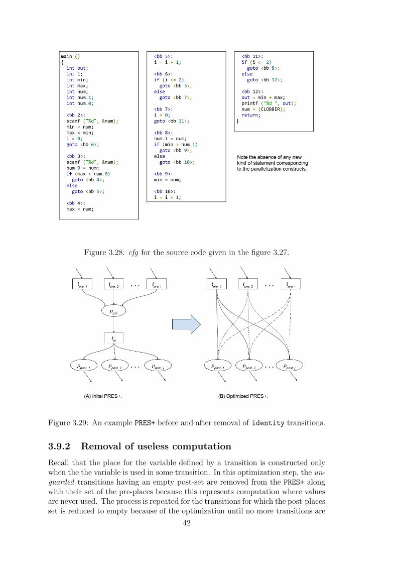
Figure 3.28: cfg for the source code given in the figure 3.27.
Figure 3.29: An example PRES+ before and after removal of identity transitions.
3.9.2 Removal of useless computation
Recall that the place for the variable defined by a transition is constructed onlywhen the the variable is used in some transition. In this optimization step, the un-guarded transitions having an empty post-set are removed from the PRES+ alongwith their set of the pre-places because this represents computation where valuesare never used. The process is repeated for the transitions for which the post-placesset is reduced to empty because of the optimization until no more transitions are
42

Figure 3.30: An example illustrating removal of useless computation.
removed from the PRES+. The guarded transitions cannot be removed even if theyhave empty sets of post-places because they perform the task of removing uselesstokens from the PRES+ as explained earlier. The optimization step is illustratedusing the following example.
Example: 3.9.1The figure 3.30(A) shows a part of a PRES+ net. In the PRES+ net, the
transition t4 has an empty post-set and hence, it is removed from the PRES+
as shown in figure 3.30 (B). As a result, the transition t3 gets an empty post-set. In this round the transition t3 is removed from the PRES+ to obtain thePRES+ as shown in figure 3.30(C) and the process shall continues until no moretransitions can be removed. �
43

44

Chapter 4
Experimental Results
Program C code Original PRES+ Optimized PRES+
Lines Places Transitions Places Transitions
Factorial 9 39 23 37 21Fibonacci 30 77 53 73 49
GCD 23 82 51 72 41Perfect Number 19 89 55 85 51
PrimalityTesting
18 67 42 64 39
Prime Factors 30 132 76 130 74Sum natural
numbers11 45 29 42 26
Triple loop 18 134 70 130 66Square Root 18 74 43 69 38
Table 4.1: Summary of simulation of the PRES+ models for some example programsin the CPN Tool.
This section provides outputs of the PRES+ construction module for some exam-ple programs. The results for some C programs tested using CPN Tool simulationare provided first. Next, the results obtained over the benchmark FSMDs are pro-vided. Finally, PRES+ models for some C are shown.
4.0.1 C Programs
Table 4.1 summarizes the testing for various examples. Following is a descriptionof each test case. “Factorial”, “Fibonacci” and “GCD” are standard programseach producing a single integer as output. “Perfect Number” and “PrimalityTesting” produce the token value 1 at the output place if the input number isperfect/prime respectively. “Prime Factors” uses the property of the CPN Tool
to gather multiple tokens in a place; it produces a token for each prime factorin the output place. Although the tool always ensures that no place gets morethan one token but an output place inside a loop can get multiple tokens as in theconcerned example. “Sum Natural Number” is the standard program to calculatethe sum of first n natural numbers. “Triple Loop” is an extension of the “Sum
45
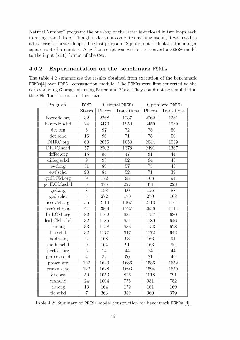
Natural Number” program; the one loop of the latter is enclosed in two loops eachiterating from 0 to n. Though it does not compute anything useful, it was used asa test case for nested loops. The last program “Square root” calculates the integersquare root of a number. A python script was written to convert a PRES+ modelto the input (xml) format of the CPN.
4.0.2 Experimentation on the benchmark FSMDs
The table 4.2 summarizes the results obtained from execution of the benchmarkFSMDs[4] over PRES+ construction module. The FSMDs were first converted to thecorresponding C programs using Bison and Flex. They could not be simulated inthe CPN Tool because of their size.
Program FSMD Original PRES+ Optimized PRES+
States Places Transitions Places Transitions
barcode.org 32 2268 1237 2262 1231barcode.schd 24 3470 1950 3459 1939
dct.org 8 97 72 75 50dct.schd 16 96 71 75 50
DHRC.org 60 2055 1050 2044 1039DHRC.schd 57 2502 1378 2491 1367diffeq.org 15 84 47 81 44diffeq.schd 9 93 52 84 43
ewf.org 31 89 57 75 43ewf.schd 23 84 52 71 39
gcdLCM.org 9 172 98 168 94gcdLCM.schd 6 375 227 371 223
gcd.org 8 158 90 156 88gcd.schd 5 272 170 270 168
ieee754.org 55 2119 1167 2113 1161ieee754.schd 44 2969 1727 2956 1714lruLCM.org 32 1162 635 1157 630lruLCM.schd 32 1185 651 1180 646
lru.org 33 1158 633 1153 628lru.schd 32 1177 647 1172 642
modn.org 6 168 93 166 91modn.schd 9 164 91 163 90perfect.org 6 74 44 74 44perfect.schd 4 82 50 81 49prawn.org 122 1620 1686 1586 1652prawn.schd 122 1628 1693 1594 1659
qrs.org 50 1053 826 1018 791qrs.schd 24 1004 775 981 752tlc.org 13 164 172 161 169tlc.schd 7 363 382 360 379
Table 4.2: Summary of PRES+ model construction for benchmark FSMDs [4].
46

4.0.3 Some example PRES+ nets
A program without loops.
#include <stdio.h>
void main ()
{
/* Simple if -else example.*/
int a, b, c, d;
scanf ("%d", &c);
a = b = 0;
if (c > 0)
a = c + 10;
else
b = c - 10;
d = a + b;
printf ("%d", d);
}
Program 4.1: A simple C program containing only one if-else statement.
Figure 4.2: The optimized PRES+ model for the program 4.1 containing an if-else
statement.
47

Figure 4.1: The un-optimized PRES+ model for the program 4.1 containing anif-else statement.
48

For loop
#include <stdio.h>
void main ()
{
/* Simple For example: Sum of First n OR 9 natural
numbers.*/
int s, x, i, n;
scanf ("%d", &n);
s = x = 0;
for (i = 0; i < n; i++)
{
x += i;
s = x;
}
printf ("%d", s);
}
Program 4.2: A C program containing only one for loop.
Figure 4.3: The optimized PRES+ model for the program 4.2 illustrating a for loop.
49

While loop
#include <stdio.h>
void main ()
{
/* Simple while Loop example: Calculates Fibonacci
. */
int f1 , f2 , n, s, i;
i = f1 = f2 = 1;
scanf ("%d", &n);
s = 0;
while (i < n)
{
i++;
s = f1 + f2;
f1 = f2;
f2 = s;
}
printf ("%d", s);
}
Program 4.3: A C program containing one while loop.
50

Figure 4.4: The PRES+ model for the program 4.3 illustrating a while loop.
51

Initialization of different arrays.
#include <stdio.h>
void main ()
{
int a1[10], a2[20], i, j;
for (i = 0; i < 10; i++)
a1[i] = 0;
printf ("%d", i);
for (j = 0; j < 20; j++)
a2[j] = 0;
}
Program 4.4: A C program containing initialization of two arrays in different loops.
Figure 4.5: The optimized PRES+ model for the program 4.4 illustrating inter loopparallelism. The parallel execution of the two loops may be noted.
52

Chapter 5
Conclusion and future work
5.1 Conclusion
The model construction mechanism consists of constructing first the PRES+ mod-els for all the basic blocks in isolation; accordingly, they appear as disconnectedsub-graphs, referred to as subnets; subsequently, they are attached to each otherto obtain the entire digraph for the PRES+ model of the complete program. Thedata structures used to store the control flow graph (cfg) of the input program,generated by the gcc and those used to represent a PRES+ model are providedfirst, followed by the mechanism to construct PRES+ subnets for individual basicblocks and attachment of the basic blocks to obtain the overall PRES+ model. Thedescription of the implementation has been organized to proceed from simpler pro-gram constructs to more complex ones. Thus, the model construction mechanismfor programs containing only input, output, assignment and if-else statementsis explained first. The mechanism is then enhanced to construct models for pro-grams containing loops, arrays and parallelization constructs. Thereafter, someoptimizations are provided on the PRES+ model. In the optimizations, data trans-fer (identity) transitions and useless computation have been removed. Finally,experimental results are provided.
5.2 Future Work
The method presented in this work handles only integer variables; the mechanismcan be extended to handle other data types also. Also, the mechanism needs tobe enhanced to handle exit control loops. Another concern is that the size of theconstructed PRES+ model is huge even after optimizations. An enhancement of thePRES+ model with a reduction in size is provided in [3]. The given method can beenhanced to produce this smaller PRES+ model. However, the existing analysis andsimulation tool (CPN Tool) reported in the work, available as a free software, willalso have to be updated to use such smaller sized representations of the models.
53

54

Appendix A
Algorithms
The various algorithms described in the implementation are summarized below.
A.1 Construction of PRES+ subnet for an individ-
ual basic block
55
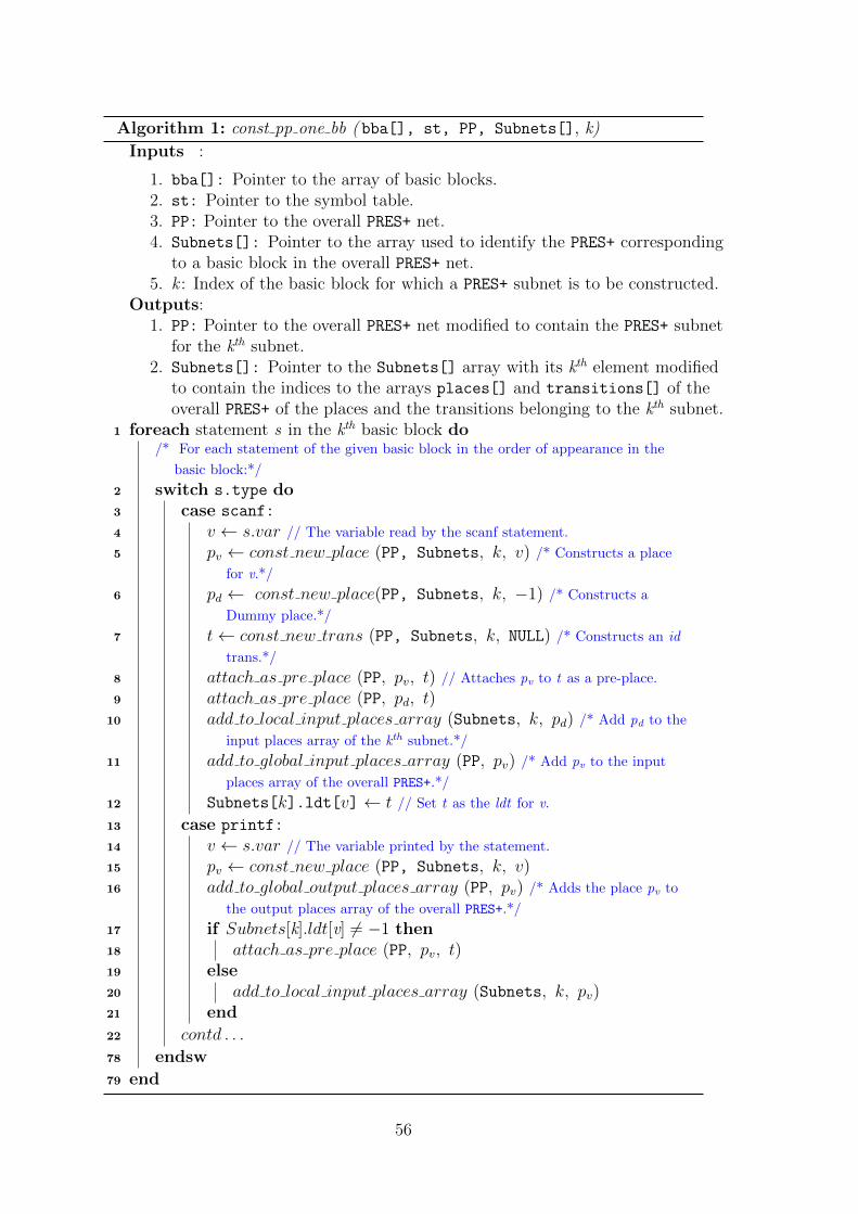
Algorithm 1: const pp one bb ( bba[], st, PP, Subnets[], k)
Inputs :
1. bba[]: Pointer to the array of basic blocks.2. st: Pointer to the symbol table.3. PP: Pointer to the overall PRES+ net.4. Subnets[]: Pointer to the array used to identify the PRES+ corresponding
to a basic block in the overall PRES+ net.5. k : Index of the basic block for which a PRES+ subnet is to be constructed.
Outputs:1. PP: Pointer to the overall PRES+ net modified to contain the PRES+ subnet
for the kth subnet.2. Subnets[]: Pointer to the Subnets[] array with its kth element modified
to contain the indices to the arrays places[] and transitions[] of theoverall PRES+ of the places and the transitions belonging to the kth subnet.
1 foreach statement s in the kth basic block do/* For each statement of the given basic block in the order of appearance in the
basic block:*/
2 switch s.type do3 case scanf:
4 v ← s.var // The variable read by the scanf statement.
5 pv ← const new place (PP, Subnets, k, v) /* Constructs a place
for v.*/
6 pd ← const new place(PP, Subnets, k, −1) /* Constructs a
Dummy place.*/
7 t← const new trans (PP, Subnets, k, NULL) /* Constructs an id
trans.*/
8 attach as pre place (PP, pv, t) // Attaches pv to t as a pre-place.
9 attach as pre place (PP, pd, t)10 add to local input places array (Subnets, k, pd) /* Add pd to the
input places array of the kth subnet.*/
11 add to global input places array (PP, pv) /* Add pv to the input
places array of the overall PRES+.*/
12 Subnets[k].ldt[v] ← t // Set t as the ldt for v.
13 case printf:
14 v ← s.var // The variable printed by the statement.
15 pv ← const new place (PP, Subnets, k, v)16 add to global output places array (PP, pv) /* Adds the place pv to
the output places array of the overall PRES+.*/
17 if Subnets[k].ldt[v] 6= −1 then18 attach as pre place (PP, pv, t)19 else20 add to local input places array (Subnets, k, pv)21 end
22 contd . . .
78 endsw
79 end
56
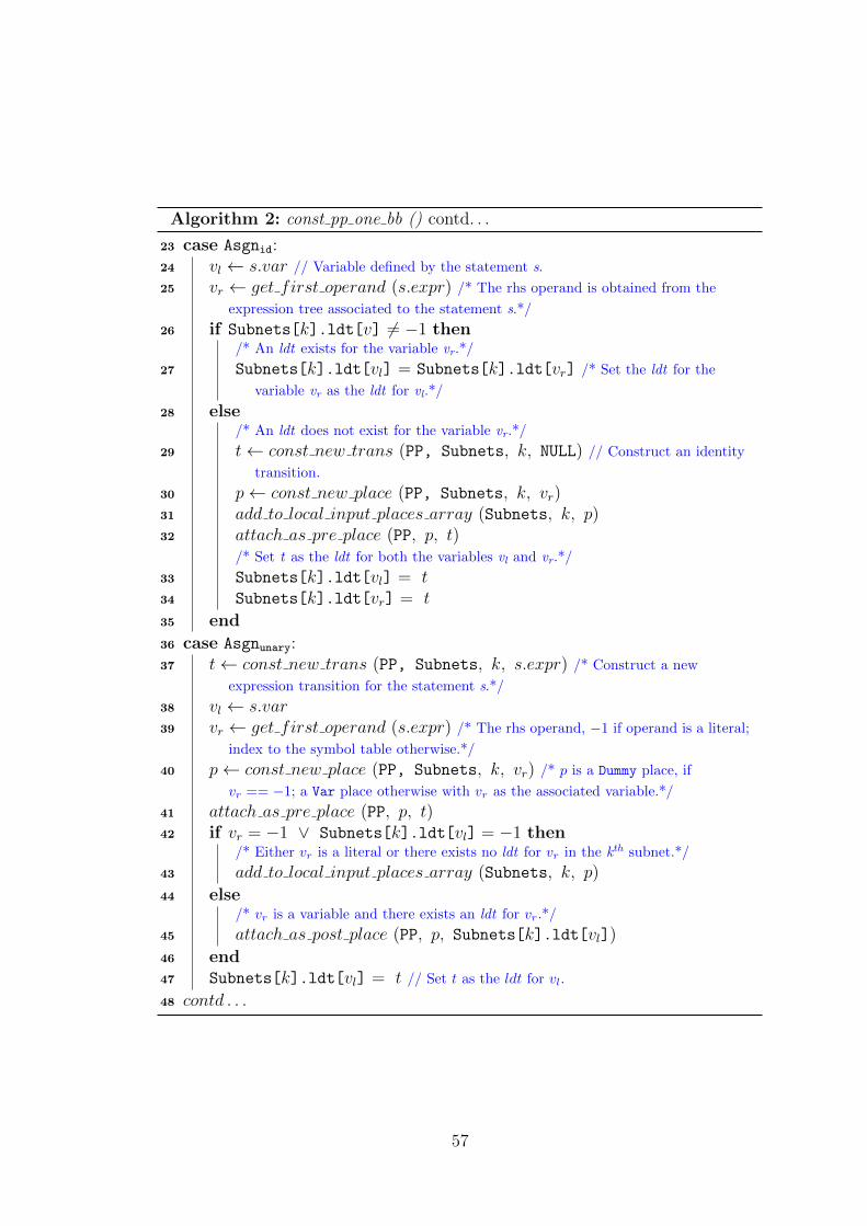
Algorithm 2: const pp one bb () contd. . .
23 case Asgnid:24 vl ← s.var // Variable defined by the statement s.
25 vr ← get first operand (s.expr) /* The rhs operand is obtained from the
expression tree associated to the statement s.*/
26 if Subnets[k].ldt[v] 6= −1 then/* An ldt exists for the variable vr.*/
27 Subnets[k].ldt[vl] = Subnets[k].ldt[vr] /* Set the ldt for the
variable vr as the ldt for vl.*/
28 else/* An ldt does not exist for the variable vr.*/
29 t← const new trans (PP, Subnets, k, NULL) // Construct an identity
transition.
30 p← const new place (PP, Subnets, k, vr)31 add to local input places array (Subnets, k, p)32 attach as pre place (PP, p, t)
/* Set t as the ldt for both the variables vl and vr.*/
33 Subnets[k].ldt[vl] = t34 Subnets[k].ldt[vr] = t
35 end
36 case Asgnunary:37 t← const new trans (PP, Subnets, k, s.expr) /* Construct a new
expression transition for the statement s.*/
38 vl ← s.var39 vr ← get first operand (s.expr) /* The rhs operand, −1 if operand is a literal;
index to the symbol table otherwise.*/
40 p← const new place (PP, Subnets, k, vr) /* p is a Dummy place, if
vr == −1; a Var place otherwise with vr as the associated variable.*/
41 attach as pre place (PP, p, t)42 if vr = −1 ∨ Subnets[k].ldt[vl] = −1 then
/* Either vr is a literal or there exists no ldt for vr in the kth subnet.*/
43 add to local input places array (Subnets, k, p)
44 else/* vr is a variable and there exists an ldt for vr.*/
45 attach as post place (PP, p, Subnets[k].ldt[vl])
46 end47 Subnets[k].ldt[vl] = t // Set t as the ldt for vl.
48 contd . . .
57

Algorithm 3: const pp one bb () contd. . .
49 case Asgnbinary:50 vl ← s.var51 o1 ← get first operand (s.expr)52 o2 ← get second operand (s.expr)53 t← const new trans (PP, Subnets, k, s.expr) Subnets[k].ldt[vl]
= t // Set t as the ldt for vl.
54 if o1 = −1 ∧ o2 = −1 then55 p← const new place (PP, Subnets, k, −1)56 attach as pre place (PP, p, t)57 add to local input places array (Subnets, k, p)
58 end59 if o1 6= −1 then
/* First operand is a variable.*/
60 p1 ← const new place (PP, Subnets, k, o1)61 attach as pre place (PP, p1, t)62 if Subnets[k].ldt[o1] = −1 then63 add to local input places array (Subnets, k, p1)64 else65 attach as post place (PP, p1, Subnets[k].ldt[o1])66 end
67 end68 if o1 6= −1 then
/* Second operand is a variable.*/
69 p1 ← const new place (PP, Subnets, k, o2)70 attach as pre place (PP, p2, t)71 if Subnets[k].ldt[o2] = −1 then72 add to local input places array (Subnets, k, p2)73 else74 attach as post place (PP, p2, Subnets[k].ldt[o2])75 end
76 end
77 end
58
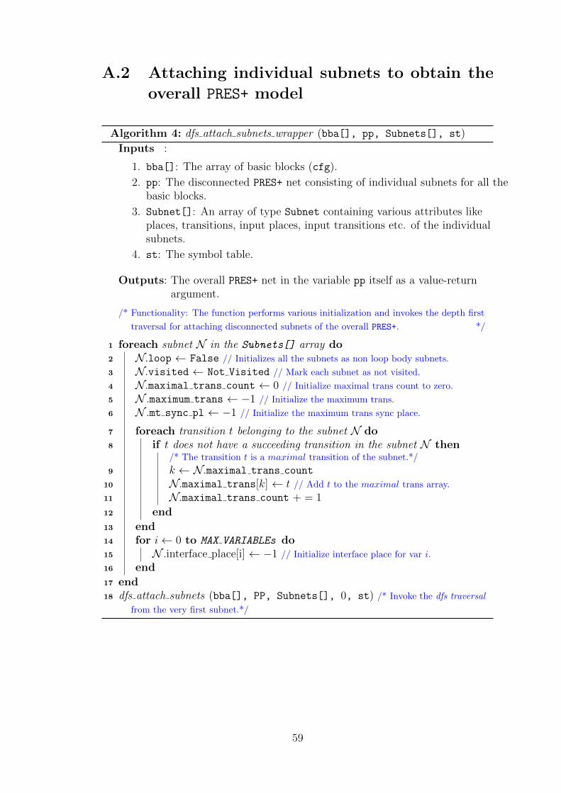
A.2 Attaching individual subnets to obtain the
overall PRES+ model
Algorithm 4: dfs attach subnets wrapper (bba[], pp, Subnets[], st)
Inputs :
1. bba[]: The array of basic blocks (cfg).
2. pp: The disconnected PRES+ net consisting of individual subnets for all thebasic blocks.
3. Subnet[]: An array of type Subnet containing various attributes likeplaces, transitions, input places, input transitions etc. of the individualsubnets.
4. st: The symbol table.
Outputs: The overall PRES+ net in the variable pp itself as a value-returnargument.
/* Functionality: The function performs various initialization and invokes the depth first
traversal for attaching disconnected subnets of the overall PRES+. */
1 foreach subnet N in the Subnets[] array do2 N.loop ← False // Initializes all the subnets as non loop body subnets.
3 N.visited ← Not Visited // Mark each subnet as not visited.
4 N.maximal trans count ← 0 // Initialize maximal trans count to zero.
5 N .maximum trans ← −1 // Initialize the maximum trans.
6 N .mt sync pl ← −1 // Initialize the maximum trans sync place.
7 foreach transition t belonging to the subnet N do8 if t does not have a succeeding transition in the subnet N then
/* The transition t is a maximal transition of the subnet.*/
9 k ← N.maximal trans count
10 N.maximal trans[k] ← t // Add t to the maximal trans array.
11 N.maximal trans count + = 1
12 end
13 end14 for i← 0 to MAX VARIABLEs do15 N .interface place[i] ← −1 // Initialize interface place for var i.
16 end
17 end18 dfs attach subnets (bba[], PP, Subnets[], 0, st) /* Invoke the dfs traversal
from the very first subnet.*/
59

Algorithm 5: dfs attach subnets (bba[], PP, Subnets[], i, st)
Inputs : The argument i holds the index of the current subnet. Otherinput arguments have same meaning as explained in thealgorithm 4.
Outputs: This function does not return anything but modifies the valuereturn arguments.
/* Functionality: This function traverses the control flow graph in depth first manner.
While backtracking the current subnet is attached to its successor(s). Subnets[i] is
referred as N in the following algorithm. */
1 if N.status 6= Not Visited then2 return;3 end4 N.status ← Visiting
// Contd. . .
60

Algorithm 6: dfs attach subnets () Contd. . .
/* Based on type of the subnet N , various operations are performed on a subnet.*/
5 if N is a Conditional subnet then/* Invoke the dfs traversal for the two successors.*/
6 dfs attach subnets (bba[], PP, Subnets[], N.true succ, st)7 dfs attach subnets (bba[], PP, Subnets[], N.false succ, st)8 if N .true succ < N then
/* N is a loop header.*/
9 const maximum trans ( PP, Subnets[], i) /* Constructs a new
maximum transition in the subnet N .*/
10 attach successors (PP, Subnets[], i) /* Attaches the N to its two
successors.*/
11 foreach predecessor Npred of N do12 if Npred.status = VISITED then
/* The edge Npred→N forms a back edge.*/
13 attach successors (PP, Subnets[], Npred)
14 end
15 end
16 else if N .true succ.loop = True then/* N is a Conditional subnet belonging to a loop body.*/
17 const maximum trans ( PP, Subnets[], i)18 attach successors (PP, Subnets[], i)
19 else/* N is a Conditional subnet not belonging to any loop.*/
20 attach successors (PP, Subnets[], i)
21 end
22 else if N is a Normal subnet then23 Ntrue succ ← N.true succ
24 switch Ntrue succ.status do25 case VISITING:
/* N → Ntrue succ is a back edge.*/
26 const maximum trans ( PP, Subnets[], i)27 const defining trans (bba[], Subnets[], PP, i) /* Constructs
defining transitions for all the variables live at the end of the subnet N .*/
28 otherwise29 dfs attach subnets (bba[], PP, Subnets[], N.true succ,
st)30 attach successors(PP, Subnets[], i)
31 end
32 endsw
33 else/* N is the last subnet, Do nothing.*/
34 end35 bba[N].status ← VISITED
61

Algorithm 7: const maximum trans(PP, Subnets[], i )
Inputs : The input parameters have their usual meaning as in precedingalgorithms.
Outputs: Return type of this function is void./* This function constructs the maximum transition for the ith subnet. The construction
is reflected in the PRES+ PP and the Subnets[] array. Subnets[i] is referred as N in
the following algorithm. */
1 t← const new trans (PP, Subnets[], i, NULL) /* Constructs an id trans.*/
2 N.maximum trans ← t /* Set t as the maximum transition for the subnet.*/
3 foreach maximal transition t′ in the Subnets[i] do/* Maximal transitions of a subnet are stored in the array maximal trans[] .*/
4 p← const new place(PP, Subnets[], i, −1) /* Constructs a Dummy
place.*/
5 attach as pre place (PP, p, t) // Attaches p to t as a pre-place.
6 attach as post place (PP, p, t′) // Attaches p to t as a post-place.
7 end
Algorithm 8: const defining trans(PP, Subnets[], i )
Inputs : The input parameters have their usual meaning as in thepreceding algorithms.
Outputs: The return type of this function is void./* This function constructs the defining transitions for the variables live at the end of
the ith subnet. The overall PRES+ PP and the Subnet[] array are modified as value
return arguments. Subnets[i] is referred as N in the following text. */
1 tm ← N.maximum trans // The maximum transition of the subnet.
2 foreach variable v live at the end of the ith subnet do3 p← const new place(PP, Subnets[], i, v) /* Constructs a place for the
variable v.*/
4 t← const new trans (PP, Subnets[], i, NULL) /* Constructs an id
trans.*/
5 attach as pre place (PP, p, t) // Attaches p to t as a pre-place.
6 if N.ldt[v] 6= −1 then/* An ldt exists for the variable v.*/
7 t′ ← N.ldt[v]8 attach as post place (PP, p, t′)
9 else/* An ldt does not exist for the variable v.*/
10 add to local input places array (Subnets[], i, p)
11 end/* Attach t to the maximum transition of N as a succeeding transition.*/
12 p← const new place(PP, Subnets[], i, −1) /* Constructs a Dummy
place.*/
13 attach as pre place (PP, p, t) // Attaches p to t as a pre-place.
14 attach as post place (PP, p, tm) // Attaches p to tm as a post-place.
15 end
62

Algorithm 9: attach successors (PP, Subnets[], i )
Inputs : The input parameters have their usual meaning as in thepreceding algorithms.
Outputs: The overall PRES+ PP is modified to reflect the attachment of theith subnet with its successors.
/* In this function Subnets[i] and N are used synonymously. */
1 Nt ← N .true succ // True successor of N .
2 if N is a Normal subnet then3 if Nt.loop = True then
/* The subnet Nt belongs to a loop body.*/
4 attach succ normal loop subnet (PP, Subnets[], i )
/* Attach the maximum trans of N to that of its successor’s.*/
5 t← N .maximum trans p← Nt.mt sync pl // Maximum trans sync
place of the succ.
6 attach as post place (PP, p, t)
7 else/* The subnet Nt does not belong to any loop body.*/
8 attach succ normal non loop subnet (PP, Subnets[], i )
9 end
10 else if N is a Conditional subnet then11 if Nt < i then
/* N is a loop header.*/
12 attach succ loop header (PP, Subnets[], i )13 attach maximum trans (PP, Subnets[], i) /* Attaches a maximum
transition to its successors’ maximum trans.*/
14 else if Nt.loop = True then/* N is a Conditional subnet belonging to a loop body.*/
15 attach succ conditional loop subnet (PP, Subnets[], i )16 attach maximum trans (PP, Subnets[], i)
17 else/* N is a conditional subnet not belonging to any loop.*/
18 attach succ conditional non loop subnet (PP, Subnets[], i )
19 end
20 else/* N is the Last subnet, do nothing.*/
21 end
63

Algorithm 10: attach maximum trans (PP, Subnets[], i)
Inputs : The input parameters have their usual meaning as in thepreceding algorithms.
Outputs: The overall PRES+ PP and the Subnets[] array are modified toreflect the attachment of the maximum transition of the ith
subnet to its successors’ maximum transitions.
/* The two successors of the subnet N .*/
1 Nt ← N .true succ2 Nf ← N .false succ44 const guarded id trans (PP, Subnets[], i , v, &tt, &tf ) /* Constructs
guarded id trans for the given variable in the two successors.*/
5 p← const new place (PP, Subnets, Nf , -1) // A new Dummy place.
6 attach as post place (PP, p, N .maximum trans)7 attach as pre place (PP, p, tt)8 attach as pre place (PP, p, tf )
/* Attach the newly constructed transitions tt and tf to the respective maximum
transition sync places.*/
9 attach as post place (PP, Nt.mt sync pl, tt)10 if Nf .mt sync pl 6= −1 then
/* There exists a maximum trans sync place in the false successor. It may not exist
if N is a loop header.*/
11 attach as post place (PP, Nf .mt sync pl, tf )
12 end
Algorithm 11: attach succ normal non loop subnet (PP, Subnets[], i )
Inputs : The input parameters have their usual meaning as in thepreceding algorithms.
Outputs: The overall PRES+ PP and the Subnets[] array are modified toreflect the attachment of a Normal subnet not belonging to aloop to the successor of the subnet.
1 Nt ← N .true succ // True successor of N .
2 foreach input place p of Nt do3 if p.type = Dummy ∨N .ldt[v] = −1 then4 add to local input places array (Subnets, i, p)5 else6 v ← p.var // The variable associated with the place p.
7 attach as post place (PP, p, N .ldt[v])
8 end
9 end
64
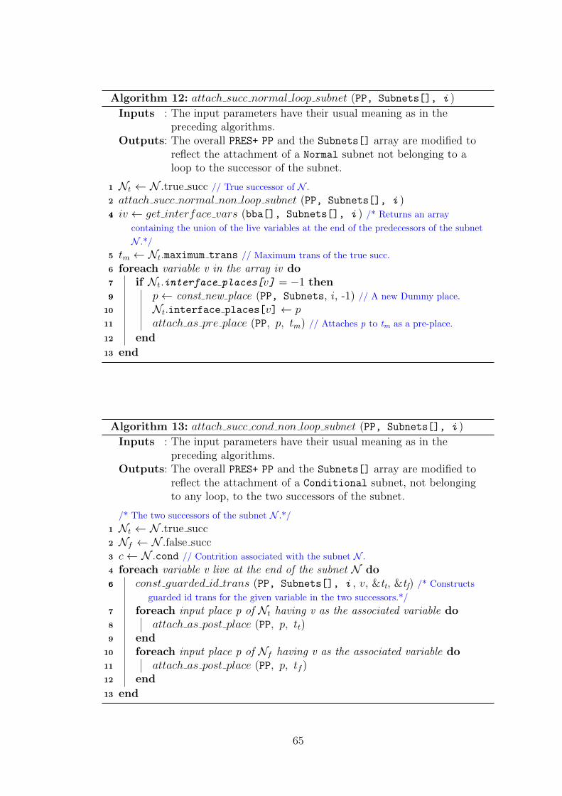
Algorithm 12: attach succ normal loop subnet (PP, Subnets[], i )
Inputs : The input parameters have their usual meaning as in thepreceding algorithms.
Outputs: The overall PRES+ PP and the Subnets[] array are modified toreflect the attachment of a Normal subnet not belonging to aloop to the successor of the subnet.
1 Nt ← N .true succ // True successor of N .
2 attach succ normal non loop subnet (PP, Subnets[], i )44 iv ← get interface vars (bba[], Subnets[], i ) /* Returns an array
containing the union of the live variables at the end of the predecessors of the subnet
N .*/
5 tm ← Nt.maximum trans // Maximum trans of the true succ.
6 foreach variable v in the array iv do7 if Nt.interface places[v] = −1 then99 p← const new place (PP, Subnets, i, -1) // A new Dummy place.
10 Nt.interface places[v] ← p11 attach as pre place (PP, p, tm) // Attaches p to tm as a pre-place.
12 end
13 end
Algorithm 13: attach succ cond non loop subnet (PP, Subnets[], i )
Inputs : The input parameters have their usual meaning as in thepreceding algorithms.
Outputs: The overall PRES+ PP and the Subnets[] array are modified toreflect the attachment of a Conditional subnet, not belongingto any loop, to the two successors of the subnet.
/* The two successors of the subnet N .*/
1 Nt ← N .true succ2 Nf ← N .false succ3 c← N .cond // Contrition associated with the subnet N .
4 foreach variable v live at the end of the subnet N do66 const guarded id trans (PP, Subnets[], i , v, &tt, &tf) /* Constructs
guarded id trans for the given variable in the two successors.*/
7 foreach input place p of Nt having v as the associated variable do8 attach as post place (PP, p, tt)9 end
10 foreach input place p of Nf having v as the associated variable do11 attach as post place (PP, p, tf )12 end
13 end
65

Algorithm 14: attach succ cond loop subnet (PP, Subnets[], i )
Inputs : The input parameters have their usual meaning as in thepreceding algorithms.
Outputs: The overall PRES+ PP and the Subnets[] array are modified toreflect the attachment of a Conditional subnet, belonging to aloop, to the two successors of the subnet.
/* The two successors of the subnet N .*/
1 Nt ← N .true succ2 Nf ← N .false succ3 ivt ← get interface vars (bba[], Subnets[], Nt) /* Returns an array
containing the union of the live variables at the end of the predecessors of the subnet
N .*/
4 ivf ← get interface vars (bba[], Subnets[], Nf )5 iv ← ivt ∪ ivf // Take union of the two arrays.
6 c← N .cond // Condition associated with the subnet N .
7 foreach variable v in the array iv do99 const guarded id trans (PP, Subnets[], i , v, &tt, &tf ) /* Constructs
guarded id trans for the given variable in the two successors.*/
10 foreach input place p of Nt having v as the associated variable do1212 attach as post place (PP, p, tt)
13 end14 foreach input place p of Nf having v as the associated variable do1616 attach as post place (PP, p, tf )
17 end18 if Nt.interface places[v] = −1 then2020 p← const new place (PP, Subnets, Nt, -1) /* A new Dummy place.*/
21 Nt.interface places[v] ← p22 attach as pre place (PP, p, Nt.maximum trans) /* Attaches p to tm as a
pre-place.*/
23 else24 p← Nt.interface places[v]25 end26 attach as post place (PP, p, tt)27 if Nf .interface places[v] = −1 then2929 p← const new place (PP, Subnets, Nf , -1)30 Nf .interface places[v] ← p31 attach as pre place (PP, p, Nf .maximum trans)
32 else33 p← Nf .interface places[v]34 end35 attach as post place (PP, p, tf )
36 end
66
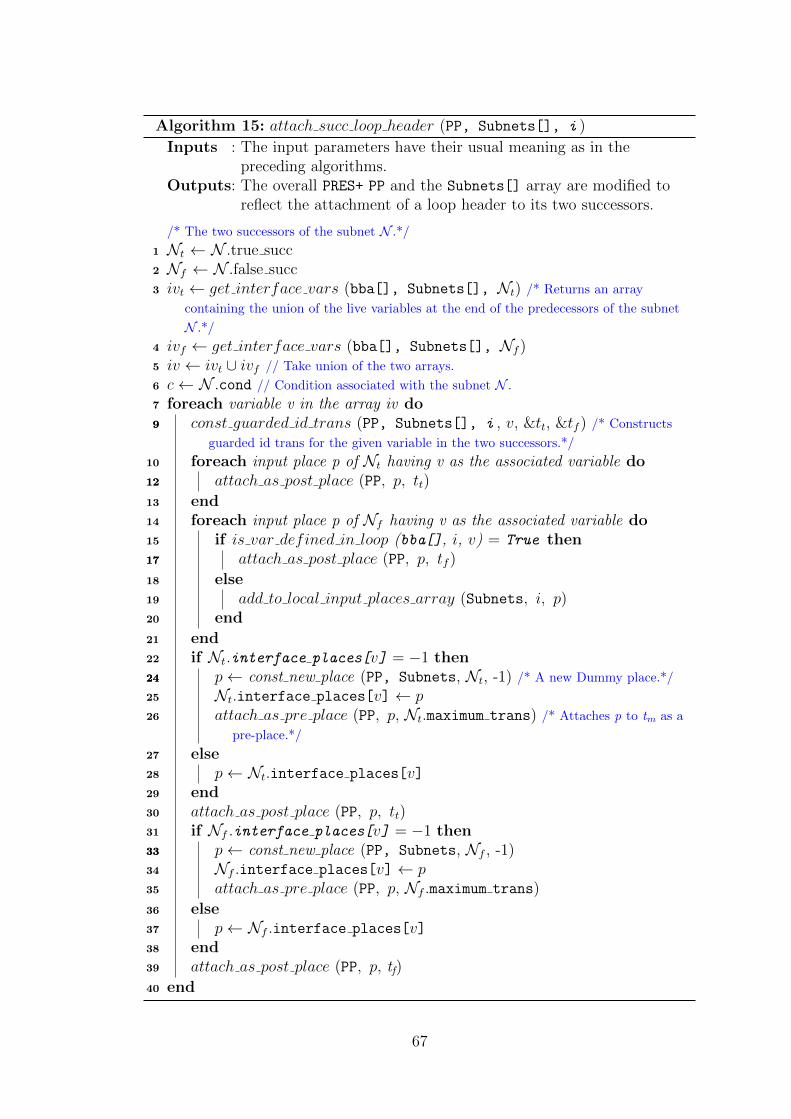
Algorithm 15: attach succ loop header (PP, Subnets[], i )
Inputs : The input parameters have their usual meaning as in thepreceding algorithms.
Outputs: The overall PRES+ PP and the Subnets[] array are modified toreflect the attachment of a loop header to its two successors.
/* The two successors of the subnet N .*/
1 Nt ← N .true succ2 Nf ← N .false succ3 ivt ← get interface vars (bba[], Subnets[], Nt) /* Returns an array
containing the union of the live variables at the end of the predecessors of the subnet
N .*/
4 ivf ← get interface vars (bba[], Subnets[], Nf )5 iv ← ivt ∪ ivf // Take union of the two arrays.
6 c← N .cond // Condition associated with the subnet N .
7 foreach variable v in the array iv do99 const guarded id trans (PP, Subnets[], i , v, &tt, &tf ) /* Constructs
guarded id trans for the given variable in the two successors.*/
10 foreach input place p of Nt having v as the associated variable do1212 attach as post place (PP, p, tt)
13 end14 foreach input place p of Nf having v as the associated variable do15 if is var defined in loop (bba[], i, v) = True then1717 attach as post place (PP, p, tf )
18 else19 add to local input places array (Subnets, i, p)20 end
21 end22 if Nt.interface places[v] = −1 then2424 p← const new place (PP, Subnets, Nt, -1) /* A new Dummy place.*/
25 Nt.interface places[v] ← p26 attach as pre place (PP, p, Nt.maximum trans) /* Attaches p to tm as a
pre-place.*/
27 else28 p← Nt.interface places[v]29 end30 attach as post place (PP, p, tt)31 if Nf .interface places[v] = −1 then3333 p← const new place (PP, Subnets, Nf , -1)34 Nf .interface places[v] ← p35 attach as pre place (PP, p, Nf .maximum trans)
36 else37 p← Nf .interface places[v]38 end39 attach as post place (PP, p, tf)
40 end
67

Algorithm 16: get interface vars (bba[], Subnets[], i )
Inputs : The input parameters have their usual meaning as in thepreceding algorithms.
Outputs: Returns an array containing the interface variables for the ith
subnet.
1 iv ← φ // Initialize to an empty array
2 if ∃ a Conditional processor of N then3 foreach processor pr of N do4 iv ← iv ∪ pr.live out /* Union with the live vars at end of each
predecessor.*/
5 end
6 else7 iv ← N .live in // Live vars at the beginning of N .
8 end9 return iv;
Algorithm 17: is var defined in loop (bba[], i, v)
Inputs : The input parameters have their usual meaning as in thepreceding algorithms.
Outputs: Returns True if the given variable is defined in the given subnet;False otherwise.
/* The two successors of the subnet N .*/
1 Nt ← N .true succ2 Nf ← N .false succ3 foreach definition d of the variable v in the reaching definitions-in set of
the basic block (subnet) Nf do4 b← d mod MAX BB STATEMENTs /* b contains the index of the subnet basic
block to which the definition d belongs.*/
5 if Nt ≤ b ≤ i then6 return True;7 end
8 end9 return False;
68

Algorithm 18: const guarded id trans (PP, Subnets[], i , v, &tt, &tf)
Inputs : The input parameters have their usual meaning as in thepreceding algorithms.
Outputs: This function constructs guarded identity transitions for thevariable v in the two successors of the ith subnet. The overallPRES+ PP and the Subnets[] array are modified accordingly.
1 Nt ← Ni.true successor // The true successor of Ni.
2 Nf ← Ni.false successor // The false successor of Ni.
44 t← const new trans (PP, Subnets, i, NULL)66 t′ ← const new trans (PP, Subnets, i, NULL)88 t.guard← Ni.cond /* Set the condition c in the if clause of the Conditional subnet
Ni as the guard of the transition t*/
9 t′.guard← ¬Ni.cond /* Set the negation of the condition c*/
10 if v 6= −1 then/* v does not represent a Dummy variable.*/
11 p← const new place(PP, Subnets, i, v)12 attach as pre place (PP, p, t)13 attach as pre place (PP, p, t′)14 if Ni.ldt[v] 6= −1 then15 attach as post place (PP, p, Ni.ldt[v])16 else17 add to local input places array (Subnets, i, p)18 end
19 end20 V ← Φ // An empty set of variables.
21 V ← {v′ s.t. v′ is a variable used in the condition c }22 foreach variable x in the set V \{v} do23 p← const new place(PP, Subnets, i, x)24 attach as pre place (PP, p, t)25 attach as pre place (PP, p, t′)26 if Ni.ldt[x] 6= −1 then27 attach as post place (PP, p, Ni.ldt[x])28 else29 add to local input places array (Subnets, i, p)30 end
31 end32 *tt ← t33 *tf ← t′
69

70

Bibliography
[1] Alfred Aho, Jeffrey Ullman, Monica S. Lam, and Ravi Sethi. Compilers: Prin-ciples, Techniques, and Tools. Addison Wesley, 2006.
[2] Soumyadip Bandyopadhyay, Dipankar Sarkar, and Chittaranjan A. Mandal.An efficient path based equivalence checking for petri net based models of pro-grams. In Santonu Sarkar, Ashish Sureka, Domenico Cotroneo, Nishant Sinha,Vibha Singhal Sinha, Radhika Venkatasubramanyam, Padmaja Joshi, R. D.Naik, Pushpendra Singh, and JayPrakash Lalchandani, editors, Proceedings ofthe 9th India Software Engineering Conference, Goa, India, February 18-20,2016, pages 70–79. ACM, 2016.
[3] Luis Alejandro Cortes, Luis Alej, Ro Corts, Petru Eles, and Zebo Peng. A petrinet based model for heterogeneous embedded systems. In in Proc. NORCHIPConference, pages 248–255, 1999.
[4] C. Karfa, D. Sarkar, C. Mandal, and P. Kumar. An equivalence-checkingmethod for scheduling verification in high-level synthesis. IEEE Transactionson Computer-Aided Design of Integrated Circuits and Systems, 27(3):556–569,March 2008.
71


