46
Construction Services Division
Construction Services Division
i
QUALITY STANDARDS AND PROCEDURES MANUAL
TABLE OF CONTENTS
PREFACE ii
PART 1 – CODES, QUALITY STANDARDS, ACCESSIBILITY REQUIREMENTS
A. Codes 1 B. Accessibility Laws, Regulations, and Minimum Standards 3 C. Quality Standards 7
PART 2 – PROCESS AND PROCEDURES A. Design and Construction Documents
1. Introduction 20 2. Licensed Design Professional Services 20 3. Pre-Application Submission 21 4. Kick-Off Meeting 22 5. Design Development Submission 23 6. Construction Documents 24 7. Pre-Construction Loan Closing (CLC) requirements 33
B. Project Delivery Methods 1. General 34 2. Design-Bid-Build 34 3. Construction Manager-at-Risk 35
C. Project Construction 1. General Conditions of Construction and Quality Control 37 2. Project Close-out 40
APPENDIX A – DOCUMENTS
1. MaineHousing and Alta Survey Requirements
2. Addendum to CM Contracts 3. MaineHousing Plan Review Process/Format Requirements
APPENDIX B - PROJECT CLOSE-OUT CHECKLIST AND FORM
1. Pre-Application Project Accessibility Worksheet 2. Kitchen Storage Evaluation Worksheet 3. Building Info/Unit Square Foot Tabulations 4. Construction Services Final Completion Checklist
5. Final Certificate/Lien Release for Contractors/Subcontractors/Vendors 6. Incomplete Work Escrow (IWE) 7. Construction Loan Closing Sign-off
ii
QUALITY STANDARDS AND PROCEDURES MANUAL
PREFACE This Quality Standards and Procedures Manual (Manual) has been assembled for use by MaineHousing’s Construction Services Division staff, and project partners and their agents, who are participating with MaineHousing in the development of safe and affordable housing through their applications for various funding sources administered by MaineHousing.
The material contained herein should be used in the design and construction of all new and rehabilitated multi-family and supportive housing projects financed all or in part by MaineHousing. This Manual establishes general and minimum performance, quality, and durability standards to ensure a basis for providing safe, sanitary, cost effective, energy efficient, accessible, and decent housing for all occupants, as well as protecting the Authority’s security interests in the property. This Manual and the addenda are also available on MaineHousing’s website: https://www.mainehousing.org/programs-services/housing-development/construction-services APPLICABILITY MaineHousing understands that not all codes, standards, processes, procedures, and documents may apply to every project, in every instance. For example, projects with limited scope, such as existing building rehabilitation supportive housing projects that do not include substantial additions or major site alterations, will likely require much less documentation and review than large-scale, new- construction or substantial rehabilitation, multi-family projects that include complete site development, require local approvals, and will include the latest materials and construction technologies and techniques.
Acquisition/rehabilitation and/or preservation projects also present unique challenges in matching work scope with available funds. In developing scopes of work for such projects the allocation of funds should be prioritized based on the specifics of each project using a hierarchy that starts with an evaluation of code compliance, including structural integrity, life-safety (may include sprinklers), hazardous materials and environmental issues, accessibility, and then an evaluation of deferred maintenance, durability, and energy concerns, and lastly include the feasibility of project upgrades and/or amenities, including any proposed additions.
Structures proposed for rehabilitation must meet, or be rehabilitated to meet, all of the new construction codes and standards contained herein, wherever reasonably and practicably possible. Re-use of existing materials, i.e., doors, windows, siding, roofing, structure, woodwork, finishes, etc., will be judged on a case-by-case basis utilizing the new construction criteria as a reference point. Any such reuse or deviations from the new construction codes and/or standards shall be reviewed and accepted by the Construction Services Division prior to implementation. It should be further noted that rehabilitation projects present unique accessibility, mechanical, structural, energy conservation and efficiency, and fire stopping characteristics/challenges that will need to be upgraded to the latest standards, in most instances. Consideration must be given to the needs to provide extermination services for all proposed buildings prior to the rehabilitation construction. All rehabilitation projects shall be evaluated for any environmental issues and any such issues shall be fully remediated as part of the project.
iii
USE OF THE MANUAL This Manual provides specific information that defines applicable codes, minimum quality and durability standards, and outlines the processes of project design, review, project delivery, and construction oversight. The use of MaineHousing, MSHA, Maine State Housing Authority, and/or the “Authority” all reference the Maine State Housing Authority. This Manual as well as a Best Practices Guide is available on MaineHousing’s website: https://www.mainehousing.org/programs-services/housing-development/construction-services
All project applicant teams are encouraged to review this Manual in detail and reach a consensus with the Construction Analyst assigned to their project as to the standards, scopes of work, processes, procedures, and documents that will be applicable for their project. A Kick-Off Meeting, as discussed later in this Manual, provides an opportune time to discuss the project scope, level of design detail, and the review procedures for each project. If consensus can’t be reached, applicants may make further requests to the Construction Services Manager of MaineHousing for final determinations of Division expectations.
STRUCTURE OF THE MANUAL This Manual has been divided into two parts plus an Appendix section:
• Part One contains the Design and Construction Codes and MaineHousing’s Quality Standards to be used in the development of contract documents
• Part Two discusses the project delivery processes and procedures and contains the Design and Construction Document requirements and document submittal procedures
• The appendix section contains additional information that is referenced in the body of the Manual
This Manual has been generated in an effort to provide a quick and easy reference for interested parties involved with the design and construction of housing projects administered by MaineHousing, and supersedes all previous editions and/or publications printed to date. This is the fourth edition of this Manual.
Final interpretations, variances, clarifications, amendments, etc. related to this Manual shall be requested from and made by the Construction Services Manager of MaineHousing.
BEST PRACTICES GUIDE MaineHousing has also created a Best Practices Guide (Guide) that provides optional additional information to help define the hoped for outcomes when developing a housing project with MaineHousing. The material contained therein provides guidance in the design and construction of all new and rehabilitation multi-family and supportive housing projects developed under the various programs administered by MaineHousing. It is the intent of that Guide to assist our partners by outlining MaineHousing’s goals and expectations to ensure an agreed upon basis for providing safe, sanitary, cost effective, energy efficient, accessible, and decent housing for all occupants, as well as protecting the Authority’s security interests in the property.
1
QUALITY STANDARDS AND PROCEDURES MANUAL
PART 1 – CODES, QUALITY STANDARDS, ACCESSIBILITY REQUIREMENTS
A. CODES MaineHousing recognizes and endorses the use of the following national, state, and/or locally adopted building, plumbing, electrical, fire protection, and engineering codes and standards as applicable as minimal requirements for all projects.
Maine Uniform Building and Energy Code (MUBEC). *Except as otherwise noted, the state adopted MUBEC is MaineHousing’s Minimum building code throughout the state.
Building Code as applicable by Project Type; which includes the following: International Building Code (IBC) 2015 International Existing Building Code (IEBC) 2015 International Residential Code (IRC) 2015
*International Energy Conservation Code (IECC) 2021 (MUBEC’s Stretch Code) ASHRAE 62.1 Ventilation for Acceptable Indoor Air Quality 2013 ASHRAE 62.2 Ventilation and Acceptable Indoor Air Quality in Low-Rise Residential Buildings 2013 ASHRAE 90.1 Energy Standard for Buildings except Low-Rise Residential Buildings 2013 ASTM E1465-08 Radon Standard for new residential construction - (Maine Model Standard) 2008
NFPA 101 Life Safety Code 2018 State Standard NFPA 211 (chimneys, etc.) 2006 State Standard NFPA 1 Fire prevention Code 2018 State Standard State Plumbing Code. (Based on IAPMO 2015 Uniform Plumbing Code) State Standard National Electric Code 2017 State Standard ADA Federal Requirement ICC/ANSI A-117.1 2009 State and Federal Requirements Fair Housing Act (design manual) Federal Standard State Fair Housing, Maine Human Rights Act State Law Section 504 (UFAS Standard or ADAAG with Exceptions per HUD deeming notice)…… ……….…………………………................................................................................Federal Standard Housing Quality Standards (HQS) Housing Choice Voucher (HCV) regulations, 24 CFR Pt 982 Uniform Physical Conditions Standard (UPCS) Federal Standard
All multi-family and/or licensed facilities shall be reviewed by and be permitted by the State Fire Marshal for both Life Safety and Accessibility requirements.
MaineHousing requires full compliance with state and local codes and/or standards for zoning and subdivision regulations.
Energy Conservation Standards MaineHousing recognizes that energy conservation is one of the best ways to manage operating costs and that controlling operating costs is the best way to ensure long term solvency of affordable residential developments that typically generate limited additional operating surpluses. Therefore, all new and renovated residential projects financed by MaineHousing shall be constructed to the following minimum energy conservation standards and requirements:
2
1. Meet the energy conservation components of the currently adopted version of the Maine Uniform Building and Stretch Energy Code editions as adopted by MaineHousing (MUBEC) for new construction which includes compliance with: a. Commercial and Mid-High Rise Residential (more than three stories)– ASHRAE
90.1, currently the 2013 version, OR IECC (optional) b. Low-Rise Single/Multi-family Residential (three stories or less) – International
Energy Conservation Code (IECC) 2021 2. MaineHousing Construction Energy Conservation Standards (Note: some of these
standards may exceed IECC requirements). a. Glazed Windows: Meet Energy Star (for Northern Climate) and NFRC rating
performance requirements and have an Air Leakage rate (AL) of
0.30 CFM/SF or less
U Factor < 0.30, or
U Factor = 0.31 and SHGC > 0.35, or
U Factor = 0.32 and SHGC > 0.40
b. Glazed Doors: Meet Energy Star performance requirements.
U Factor < 0.21, or
U Factor = 0.27 and SHGC > 0.30, or
U Factor = 0.32 and SHGC > 0.30
c. Glazed Skylight: Meet Energy Star performance requirements.
U Factor < 0.55
d. Max. Glazed area: One and two family dwellings: 15% of the gross insulated exterior
wall area.
All other buildings: 25% of the gross insulated exterior wall area.
Note: This requirement applies to all glazed components in the
exterior walls of the building as a whole. Proposals that exceed
listed maximum glazed areas shall provide increased performance
values, supported by an energy analysis, in other insulation envelope
systems or glazed systems that equal the additional performance loss
incurred by the increased glazing area proposed.
e. Insulated Doors: U Factor < 0.15 + Air Leakage Rate < 0.30 cfm/SF f. Ceiling R Value: IECC 2021: R 60, with equivalent R value full depth of top plate g. Exterior Walls: IECC 2021: Cavity R/Continuous R; 20+5 or 13+10; with equivalent
R value full depth at perimeter joist framing, all levels h. Framed Floors: IECC 2021: Zone 6: R 30; Zone 7: R 38; with equivalent R value full
depth at perimeter joist framing, all levels i. Basement Walls: IECC 2021: Above exterior grade: match the Above Grade Exterior
Wall R value
Below exterior grade: IECC 2021; Cavity/Continuous R; 15/19
j. Foundations: Below exterior grade, horizontal and vertical: per IECC 2021 k. Interior Slabs: Inboard of Foundation: IECC 2021; R 5 minimum
3. MaineHousing Existing Facilities Energy Conservation Standards (exempt by MUBEC) a. Adaptive Re-Use: Creation of new residential units - meet overall
performance of New Construction MaineHousing Energy Conservation Standards supported by a building energy model that demonstrates equal “Whole building” performance compared to the New Construction Energy Conservation standards. This recognizes that, many situations, the individual standards may be difficult to achieve and, accordingly, meeting the new building performance for
3
the building as a whole by other means is an acceptable alternative to meeting individual component requirements.
b. Preservation: Preservation of existing housing units – balance Redevelopment needs including air-sealing, weatherproofing, durability, marketability and energy conservation to provide the best long term operating benefit, supported by an operating budget analysis, while striving to meet the performance values of the Energy Conservation Standards, where possible.
c. Historic Re-use: Re-use of Historic Structures- balance historic preservation objectives with requirements of both Change of Use and Preservation strategies (see above).
B. ACCESSIBILITY LAWS, REGULATIONS, AND MINIMUM STANDARDS MaineHousing’s Accessibility Policy and Procedures for the Design and Construction of Multifamily and Supportive Housing Projects is incorporated by reference in this Manual. The policy and procedures can be found on MaineHousing’s website at: https://www.mainehousing.org/docs/default-source/development/2019-updated-mainehousing-accessibility-policy-and-procedures.pdf?sfvrsn=d7c9b315_2 MAINEHOUSING MINIMUM ROOM SIZES MaineHousing herein establishes minimum room sizes and critical space dimensions for use by all designers and Owners. Projects must meet all of the following requirements:
1. Minimum Dwelling Unit Room Sizes In order for a dwelling unit to be considered for funding it must meet the following minimum criteria before it can be submitted to Construction Services for review and/or approval: Separate Living, Dining, Bedrooms
Living area: Each dwelling unit shall contain space that is conducive to general family living and group activities such as entertaining, reading, writing, listening to music, watching television, relaxing and children’s play. Dining Area: Each dwelling unit shall contain space for dining. This area may be combined with the living room or kitchen, or it may be a separate room. Bedrooms: Each dwelling unit shall contain space(s) allocated to sleeping, dressing, and personal care. All beds shall have sufficient maneuvering space from two sides and one end.
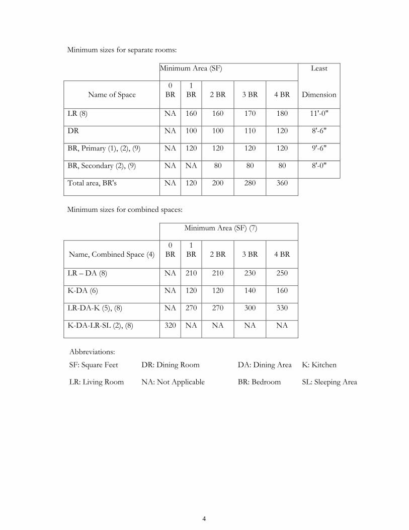
2. Minimum Room Sizes by square foot area:
The table below shall be used when designing the designated paces. The table shall be used throughout the project for all rooms of all dwellings. All dimensions and area calculations are to be based on interior finished face of wall surfaces (not framing) as the point of measurement. Spaces for closets or storage are NOT to be included within the minimum SF for the rooms/spaces listed in the table.
4
Minimum sizes for separate rooms:
Minimum Area (SF) Least
Name of Space
0 BR
1 BR
2 BR
3 BR
4 BR
Dimension
LR (8) NA 160 160 170 180 11'-0"
DR NA 100 100 110 120 8'-6"
BR, Primary (1), (2), (9) NA 120 120 120 120 9'-6"
BR, Secondary (2), (9) NA NA 80 80 80 8'-0"
Total area, BR's NA 120 200 280 360
Minimum sizes for combined spaces:
Minimum Area (SF) (7)
Name, Combined Space (4)
0 BR
1 BR
2 BR
3 BR
4 BR
LR – DA (8) NA 210 210 230 250
K-DA (6) NA 120 120 140 160
LR-DA-K (5), (8) NA 270 270 300 330
K-DA-LR-SL (2), (8) 320 NA NA NA NA
Abbreviations:
SF: Square Feet DR: Dining Room DA: Dining Area K: Kitchen
LR: Living Room NA: Not Applicable BR: Bedroom SL: Sleeping Area
5
Notes applicable for both methods of room designs and layouts: 1. Primary bedrooms shall have at least one wall of at least 10 feet uninterrupted by
openings less than 44 inches above the floor. 2. Normally closed door swings, such as closet doors in bedrooms, that when
opened intrude on the requirements in 1. above are not considered as a reduction of the stated dimensional requirement.
3. In bedrooms, the requirements in 1. above shall be free of any permanent construction elements, such as closets, for a minimum distance of 8’ out from the wall (i.e. a minimum 10’ X 8’ clear area for a bed and access).
4. All bedrooms or sleeping areas shall have at least one operable window in the exterior envelope wall.
5. The minimum dimensions of a combined room shall be the sum of the dimensions of the individual single rooms involved, except for the overlap or combined use space.
6. For two adjacent spaces to be considered a combined room, the horizontal opening between spaces shall be at least 8’–0”, except that between kitchen and dining functions, the opening may be reduced to 6’-0”. Spaces not providing this degree of openness shall meet minimum room sizes required for separate rooms.
7. A combined LR-DA-K shall have a clear passage opening between the kitchen and dining area of at least 4’-0”.
8. These required minimums apply when the only eating space is in the kitchen. 9. The floor area of an alcove, or recess off a room, having a least dimension less
than required for the room, shall be included only if it is not more than 10 percent of the minimum room size permitted and is useful for the placement of furniture.
10. All Living room spaces shall have at least one operable window in the exterior envelope walls.
11. A Bedroom is a fully enclosed room with fixed walls and a door that provides complete visual and acoustical privacy.
3. Kitchen: a. Each living unit shall include adequate space to provide for efficient food
preparation, serving and storage, as well as utensil storage and cleaning up after meals.
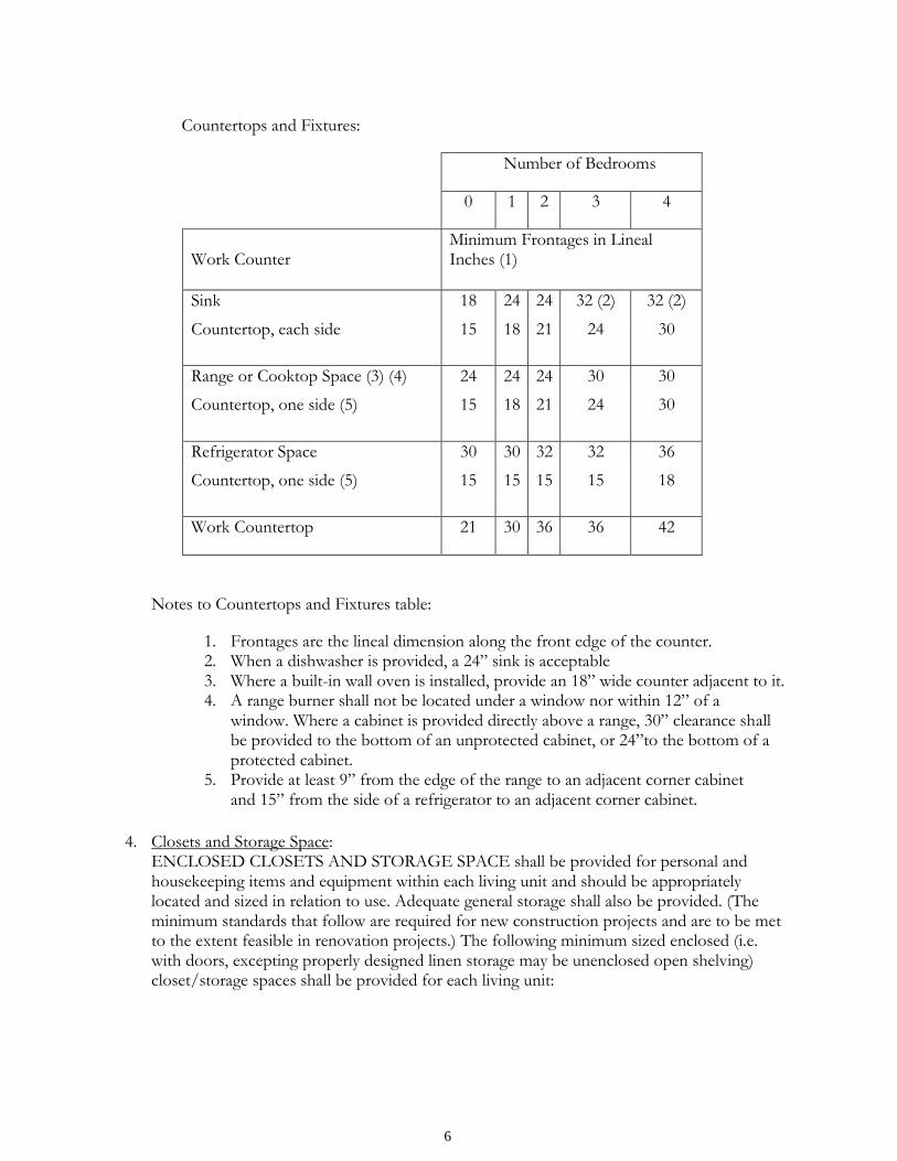
b. Kitchen fixtures and countertops shall be provided in accordance with the table below. Required countertops shall be approximately 24” deep and 36” high (except for units specifically designed and fitted to meet accessibility codes and/or regulations). Clearance between base cabinet fronts in food preparation area shall be 40” minimum (except for units specifically designed and fitted to meet more stringent accessibility codes and/or regulations).
c. Required countertops may be combined when they are located between two fixtures – stove, refrigerator, sink. Such a countertop shall have a minimum frontage equal to that of the larger of the countertops being combined. This combined counter may also be the work counter when its minimum length is equal to that required for the work counter. Countertop frontages may continue around corners.
6
Countertops and Fixtures:
Number of Bedrooms
0 1 2 3 4
Work Counter
Minimum Frontages in Lineal Inches (1)
Sink 18 24 24 32 (2) 32 (2)
Countertop, each side 15 18 21 24 30
Range or Cooktop Space (3) (4) 24 24 24 30 30
Countertop, one side (5) 15 18 21 24 30
Refrigerator Space 30 30 32 32 36
Countertop, one side (5) 15 15 15 15 18
Work Countertop 21 30 36 36 42
Notes to Countertops and Fixtures table:
1. Frontages are the lineal dimension along the front edge of the counter. 2. When a dishwasher is provided, a 24” sink is acceptable 3. Where a built-in wall oven is installed, provide an 18” wide counter adjacent to it. 4. A range burner shall not be located under a window nor within 12” of a
window. Where a cabinet is provided directly above a range, 30” clearance shall be provided to the bottom of an unprotected cabinet, or 24”to the bottom of a protected cabinet.
5. Provide at least 9” from the edge of the range to an adjacent corner cabinet and 15” from the side of a refrigerator to an adjacent corner cabinet.
4. Closets and Storage Space:
ENCLOSED CLOSETS AND STORAGE SPACE shall be provided for personal and housekeeping items and equipment within each living unit and should be appropriately located and sized in relation to use. Adequate general storage shall also be provided. (The minimum standards that follow are required for new construction projects and are to be met to the extent feasible in renovation projects.) The following minimum sized enclosed (i.e. with doors, excepting properly designed linen storage may be unenclosed open shelving) closet/storage spaces shall be provided for each living unit:
7
a. BEDROOM CLOSETS - each bedroom (or in the case of zero bedroom units, each sleeping area) shall have readily accessible clear hanging space equipped with a rod and shelf as follows:
Primary and/or double occupancy bedrooms: 2’- 0” deep by 5’ – 0” wide by 7’ – 0” high minimum Secondary and/or single occupancy bedrooms: 2’- 0” deep by 3’ – 0” wide by 7’ – 0” high minimum
b. COAT CLOSET - At least one coat closet with a hanging rod and shelf
convenient to the main entrance of all units: 2’ – 0” deep by 2’ – 0” wide by 7’ – 0” high minimum
c. LINEN STORAGE in all
units: Minimum shelf area: 10 SF for 2 bedrooms or less; 15 SF for 3 bedrooms or more.
Shelves to be spaced at least 6” but not more than 12” o.c. vertically, and shelving over 74” above the floor shall not be counted as part of the required shelf area. It is recommended that all shelving in units equipped with accessible features include fully adjustable shelving to accommodate various reach range requirements.
GENERAL STORAGE space shall be provided for the storage of items and equipment essential to the use of the occupants. This storage requirement or capacity is separate from, and in addition to, required closets listed above and/or kitchen storage. General storage may be integrated with required closet space, by separate storage closet(s) within the unit, in assigned/secured storage areas within the same building, or assigned/secured storage areas in separate buildings.
GENERAL STORAGE REQUIREMENTS (in cubic feet)
Dwelling Size: CF: 0 Bedroom 50 1 Bedroom 100 2 Bedrooms 100 3 Bedrooms 150 4 or more Bedrooms 175
Storage spaces less than four feet or more than eight feet in height, or more than four feet in depth without two feet of access space shall not be included within the required volume. Storage area requirements shall not include access space and/or door swing space.
C. QUALITY STANDARDS MaineHousing has experienced that certain materials and/or construction practices are uneconomical when considered over the life of the project or are the cause of reoccurring problems. Therefore, outlined in this section are specific materials, installations, and construction practices that have demonstrated proven performance characteristics, minimum quality and/or durability, and are appropriate to the developments it wishes to finance.
8
In general, MaineHousing’s quality standards are meant to complement, supplement, or improve upon any national, state, or local regulations. However, in any situations where conflicting requirements occur, the more stringent standard, regulation, law, or procedure shall apply.
Division 1, General Conditions
1. RESERVED
Division 2, Sitework
1. GEOTECHNICAL INVESTIGATION reports, shall be either referenced and be readily available for viewing or be included in the project manual. Note: Projects of limited site work scope, such as renovations to existing structures, may not be required to provide geotechnical investigations. Such scopes shall be reviewed and a determination of applicability shall be made by the project’s construction analyst.
2. SOIL TESTING services from a qualified testing agency shall be retained by owner or contractor to monitor and test all critical soil fill operations.
3. POSITIVE DRAINAGE slopes away from all buildings shall be provided; a 6” pitch in the first 10 feet is a recommended minimum slope. In the event of the inability to provide such natural drainage, an engineered drainage system may be provided.
4. FOUNDATION DRAINS shall be provided for all foundation types including frost wall designs. These drains shall be provided both inside and outside of all walls unless soil and/or site conditions can adequately justify alternative designs. Soils Engineers’ (geotechnical) reports must be provided as part of any requests for alternatives. These drains should connect to a permanent and positive storm drainage system or daylight to a properly designed surface drainage system. All daylight drains should have their outlooks screened and protected from erosion and the entrance of rodents. Backflow preventers should be provided for all foundation drains.
5. PASSIVE OR ACTIVE UNDER SLAB RADON VENTING SYSTEMS shall be provided beneath all slabs-on-grade and measures should be taken to prevent unwanted air leakage into the gas permeable layer. The interior radon piping should be run within the thermal envelop and be properly labeled. All passive system pipe routes shall provide space for installing a radon fan and a monitor should testing confirm the need for such added components. Provide an electrical supply adjacent to the vent stack that is located above the highest occupied space and provides adequate clearance for the potential future installation of a fan. Consideration should be given for access to this location. Whenever practicable, the system should be vented through the highest roof or ridge in such a position that it cannot be covered by snow or other material. The vent stack discharge shall meet the separation distances required by code from any window, door, or other opening into the conditioned space. Active systems may be required if radon testing confirms the need for such added capacity.
6. FLOOR DRAINS AND/OR SUMPS shall be provided in all basements. The floor should be pitched to these drains or sumps and, to the maximum extent feasible, these should be connected to a positive drainage system, exterior of the building to daylight or to a storm water system. Connections to storm water systems should be equipped with backflow preventers. Any such floor penetrations shall be tightly sealed against radon gas entry.
7. SUBSURFACE DRAIN PIPING of styrene or corrugated polyethylene pipe may be used for foundation drains, leaching fields, or other below grade applications only when the materials and its installation are in accordance with ASTM Standards. Rigid perforated PVC pipe is also permissible provided the minimum wall thickness for 4”

9
pipe is 0.075”, and for 6” pipe is 0.10”, and it is installed in accordance with applicable ASTM Standards.
8. POLYETHYLENE OR OTHER APPROVED VAPOR/MOISTURE/RADON BARRIER MATERIAL shall be placed under all concrete slabs, including basement and/or crawl space and on-grade floors. Polyethylene under slabs and in crawl spaces shall be at least six (6) mils thick and shall have all joints lapped a minimum of six inches and sealed with mastic or tape. All pipe or other penetrations shall have the vapor/moisture/radon barrier taped around them in a secure fashion to prevent moisture and/or gas infiltration.
9. LIQUID ASPHALT AND/OR GRAVEL ROADS AND/OR DRIVES are not acceptable within the project bounds. Such surfaces, if acceptable by town standards, may be considered up to the project bounds.
10. EROSION during and after construction shall be controlled in accordance with the “Standards and Specifications” published in the “Environmental Quality Handbook” by the Maine Soil and Water Conservation Commission.
11. FOUNDATION FOOTINGS shall be constructed on undisturbed material unless otherwise specified by the designer-of-record. All fill placed under footings must be engineered fill, designed, tested, and certified by a Professional Engineer, registered in the State of Maine.
12. PARKING shall be provided at a minimum of 1 parking space per dwelling unit. This shall include one properly sized and identified space per accessible unit as required by laws or regulations. One space per pledged accessible unit is encouraged but only required upon request for accommodation. It is suggested that site planning include reserving space for any such future accommodations. Accessible parking spaces shall be provided at the same ratio as overall parking spaces in the event that less than 1:1 parking is accepted. Accessible van parking for tenants shall be provided at a ratio of 1 per every 6 accessible spaces per accessible unit as required by laws or regulations (not including pledged units) or as needed for requests for accommodation. For sites with limited developable area for on-site parking such that 1:1 unit/parking ratio cannot be met or is not justified, an alternative parking plan will be considered by MaineHousing on a case-by-case basis. In order to be considered for less than a 1:1 unit/parking ratio, the Developer shall, as part of the pre-application phase, document a plan that meets the local municipality’s requirements or, if none are available, the following:
a. Documents the demand for on-site or off-site parking consistent with projects of similar size, location, and population.
b. Documents the availability and costs of transportation alternatives that service the project site.
c. Describes alternatives to car parking that will be provided on-site such as parking for motorcycles and/or scooters and/or storage for bicycles.
d. Describes any proposed tenant incentive programs that will reduce car parking needs.
e. Describes tenant education efforts that will be implemented that will reduce car parking needs.
f. Provides for timely and ongoing monitoring of the plan and describes how adjustments to the plan will be implemented.
g. In addition to the documented plan, a written acceptance from the Municipality of the plan shall be provided.
10
13. PARKING SPACES shall be permanently delineated upon the pavement. Accessible parking areas shall be so marked on the surface and properly signed.
14. WHEEL STOPS may be provided for parking stalls based on topography, drainage, pedestrian separation needs, protection of improvements, etc. These may be pre-cast concrete stops or materials of similar size and mass acceptable to MaineHousing. Standard asphalt curbing, if used as a wheel stop, shall be backed up with full depth compacted earth fill.
15. PAVED AREAS within the subject property that are deemed in need of new bituminous concrete paving will be required to meet the following:
a. Prior to the laying of the new bituminous concrete paving (pavement) the existing paving shall be removed completely. All exposed gravel base material shall be inspected for contamination by silts or other foreign, deleterious material. Any contaminated base is to be removed down to clean, sound material. Unless otherwise designed and specified by a design professional, the removed material should be replaced with aggregate base material as per M.D.O.T. Sec. 703.06 Type A. All new material should generally be evenly spread in lifts not to exceed eight (8”) inches in depth and compacted in place to a minimum of 95% of the maximum density as per ASTM D1 557. Minimum total base thickness shall be 18” for Roadways and Parking Areas; 12” for Walkways and Ramps.
b. Minimum compacted thickness and mix design for the pavement courses shall be: c. Base/Binder Course: 2” MDOT Type B (19 mm) d. Surface/Finish Course: 1” MDOT Type D (9.5 mm) e. Existing and new surfaces shall meet in a smooth continuous plane free from
variations in height or smoothness. Clean and treat all areas thoroughly prior to installation of asphalt.
f. The temperature of the pavement mix shall be regulated to ensure that at the time of spreading the mix is within specifications. Pavement having temperatures outside of the specified temperature range when dumped into the spreader should be rejected.
g. The pavement mixture shall be thoroughly compacted by rolling. Rolling is to begin as soon as the placement of the mixture will bear the roller without undue displacement or delay.
h. The construction of the new pavement shall be carried on only when the surface on which the mix is to be placed is dry, and when the surface temperature of the underlying course is greater than 45 degrees F for course thickness greater than one- inch and 55 degrees F for course thickness one-inch or less.
i. It shall be the Contractor’s responsibility to prohibit vehicular traffic, including heavy equipment, from traveling upon the pavement until the surface temperature has cooled to 120-degrees F.
16. SOILS USED FOR PLANTINGS, PLANTING BEDS, AND GRASSED AREAS are to be purposely specified and field tested for conformance to the construction documents. Lawn areas of projects should be planted and properly maintained to assure proper establishment coverage and growth. Because plantings and grass growth are season dependent, an Incomplete Work Escrow (IWE) in the amount of the cost of the work as determined by the Construction Services Division Analyst, grossed up by 150% to assure adequate funds are secured, may need to be established at the conclusion of the project and will be held by MaineHousing until the work is completed to the satisfaction of the Construction Services Division.
17. SMOKE-FREE SIGNAGE provide adequate notice to building occupants, visitors, guests and employees of the scope and extent of applicability of the project’s smoke-
11
free status (re: reduction of exposure to Environmental Tobacco Smoke (ETS)). To effectively accomplish this, provide conspicuous notices (building and/or site signage) of ‘smoke free’ status at all entry ways to smoke free buildings, and, if applicable, at the points of entry for vehicles or for foot traffic onto the grounds of the property. Notices, at a minimum, shall be: “Smoke Free Building” and “Smoking Prohibited 25 feet from entryways, windows, vents and balconies” or “Smoke Free Property” (as the case may be). Signage shall meet applicable signage design requirements of the Americans with Disabilities Act of 1990.
18. EXTERIOR WALKWAYS, PARKING AREAS AND UNLOADING AREAS and other exterior routes and features that are required to be accessible shall be finished with asphalt or concrete. Stone dust is not an acceptable ground cover for accessible routes.
Division 3, Concrete
1. FOUNDATION DESIGN shall be consistent with the findings and recommendations of the geotechnical engineer’s soils report.
2. CAST-IN-PLACE CONCRETE shall achieve the following minimum 28 day compressive strengths: Footings: 3,000 PSI; Foundation walls: 3,000 PSI; Interior flatwork: 3,000 PSI; Exterior flatwork: 4,000 PSI with 5-7% air entrainment. All concrete shall be designed and specified by the designer-of-record for both strength and durability; strengths listed herein are minimums for durability.
3. ADMIXTURES proposed for use in concrete shall be used in accordance with the American Concrete Institute’s recommendations with the exception of calcium chloride which is undesirable due to the side effects and conditions it creates within the concrete. Accelerating admixtures, if needed, are to be used in place of calcium chloride. The accelerator used should be a national brand which has been performance tested. Any and all admixtures shall be specified by the designer-of-record and be used in strict accordance with the manufacturer’s instructions.
4. CONCRETE TESTING shall be conducted by a qualified testing agency retained by the owner or contractor to monitor and test all structural concrete. Concrete placement records shall be provided by the testing agent to the Owner, Contractor and MaineHousing of all slump and strength tests required in accordance with ACI documents and/or specifications. At a minimum, there should be one strength test for each 50 cubic yds. or fraction thereof of material placed in any one day. Three (3) test cylinders constitute one strength test; one cylinder is tested at 7 days for information only; 2 cylinders are tested at 28 days to determine acceptance. It is recommended that a fourth cylinder be cast in case a 56 day test becomes necessary.
Division 4, Masonry: 1. All masonry ties and anchors for veneer walls shall be stainless steel.
Division 5, Steel & Metals
1. STEEL TESTING shall be conducted by a qualified testing agency retained by the Owner or general contractor to monitor and test all steel fabrications.
2. ALL STRUCTURAL ELEMENT FIELD-WELDING should be third party inspected and/or tested and appropriate documentation provided to assure quality of welds consistent with the construction documents requirements.
12
Division 6, Carpentry 1. PRESSURE TREATED (PT) LUMBER shall meet manufactures’ requirements for
installation location, e.g., framing in contact with concrete or masonry; or posts embedded in soil. Fasteners and hangers are to be hot dipped galvanized or stainless steel. Metallic flashings, except copper, are to be isolated from PT lumber.
2. DRYWALL OR OTHER HARD CEILING FINISHES in buildings with the bottom chords of roof trusses or floor framing spaced at 24” on center shall be installed on wood strapping or resilient channels spaced at a maximum of 16” on center.
3. WOOD FOUNDATIONS are not permitted without the express approval of MaineHousing and may be suggested only when all other proven methods of foundation construction have been eliminated, and/or when MaineHousing determines for a particular installation that wood foundations constitute a substantial advantage over other materials. The system must be listed and certified by a national listing service.
4. INTERIOR TRIM OF COMPOSITION OR PARTICLE BOARD with or without plastic coating, is not permitted.
5. COMPOSITE or particle board shelving is not permitted. 6. NEW STAIRS serving more than one dwelling unit shall provide a minimum clear width
of 44’’ unless otherwise required to be wider by code. 7. UNDERLAYMENT, as required by product manufacturers shall be provided at all
areas scheduled to receive sheet vinyl, linoleum, rubber, or VCT finish flooring materials.
Division 7, Thermal and Moisture Protection
1. POLYETHYLENE (MINIMUM 6 MILS THICK) VAPOR BARRIERS shall be placed on the interior surfaces of all envelope framing that is insulated with fiberglass insulation. All joints and penetrations shall be properly sealed to prevent moisture migration.
2. SPECIALTY INSULATION PRODUCTS such as wood fiber shall be presented to and be reviewed by MaineHousing for approval prior to use in any project. Products that provide superior air-sealing qualities are encouraged. Any such products shall be installed per industry standards and be protected per the State Fire Marshal’s requirements.
3. INSULATION such as R-5 closed cell rigid insulation or R-5 composite, cross woven polyethylene, aluminum and polyethylene closed cell foam core blankets are required beneath the entire floor slab-on-grade floor area. Note: The use of composite blankets beneath slabs-on-grade must be used in conjunction with R-10 foundation wall insulation as follows: Rigid insulation, minimum R-10 vertically continuous from footing to under slab AND rigid insulation, minimum R-10, 2’ – 0” in horizontally around the entire slab perimeter. To assure an effective moisture barrier is provided, all blanket seams shall be securely sealed utilizing blanket manufacturer’s recommended products. All blankets are to be placed on top of horizontal rigid insulation and be continuous from outside wall to outside wall.
4. ALUMINUM AND T-1 11 WOOD SHEETING are not permitted as siding materials on any buildings.
5. VINYL SIDING AND TRIM shall be a minimum of .044” thickness. 6. ROOF SHINGLES shall be a minimum standard of quality of a 30-year warranty organic
asphalt or fiberglass. Heavier grade, “Architectural” shingles are strongly recommended. 7. EPDM ROOFING shall be a minimum standard of quality is equal to Firestone fully
adhered (0.060) system, with a minimum 15 year Full System Warranty. 8. FLASHING AND SHEET METAL roof drip edge shall be 0.032’’ min aluminum
(galvanized steel is not permitted).

13
9. THE USE OF “ICE & WATERSHIELD” BY W.R. GRACE CO. OR MAINEHOUSING APPROVED EQUAL is required for all drip edge (minimum 6’ up the roof), rake (minimum 3’ in from roof edge, and valley underlayments beneath shingles (minimum of 4.5’ up each side of valley). Also, roof to wall intersections shall receive an additional layer of the same fabric flashings/underlayments, run up walls and onto roof substrates 18” minimum.
10. THE BUILDING ENVELOPE must be air-sealed to prevent leaks. All penetrations through the building envelope must be carefully sealed. Typical penetrations include chimney, duct & plumbing chases and penetrations of pipes and wires through the top plates of top story walls. It is particularly important to seal all possible air paths to the attic. Other items to consider and apply (but not limited to):
a. Provide gaskets or sill seals under mud sills along foundation walls. b. Seal first floor band joists to the adjoining mud sills and plywood decking
using adhesive or caulk. Use construction adhesive or caulking between multiple sill plates, gaps in envelope framing, and at joints of adjoining exterior frame panels.
c. Seal any band joists between upper floors to the adjoining top plates and plywood decking.
d. Use construction adhesive or caulking between multiple top plates. e. Seal bottom plates of exterior frame walls to the sub-floor with
construction adhesive or caulking. f. Avoid locating bathtubs and shower enclosures on exterior walls. If installed
on exterior walls or party walls, insulate and air-seal this area BEFORE shower/tub is installed.
g. Recessed lights must be air-sealed and airtight. (Recessed lights may not penetrate the building envelope).
h. Window frames and door jambs must be sealed to their rough openings using low expansion foam, backer rod or caulk but NOT fiberglass.
i. Building areas such as knee wall-floor transitions, dropped soffits, split-level transitions, tuck-under garages and cantilevers must be identified and sealed with a continuous air barriers and thermal insulation.
j. Where joist spans or stud bays run between a heated and unheated area all bays must be blocked and sealed at the transition.
k. Attic and crawl space access doors and hatches must be weather-stripped and insulated.
l. Electrical boxes on exterior walls and ceilings should either be air-sealed or placed in airtight enclosures/systems (LESSCO boxes or equivalent). Note: These air-tight enclosures may be excluded at the designer’s option when spray foam insulation providing equivalent air-sealing is utilized.
m. Dehumidification systems should be considered for unconditioned basement spaces.
11. BLOWER DOOR TESTING is required for each project and is to include either a
whole building test, if possible, based on building type and configuration, or a representative number of units, as determined by MaineHousing, to verify effectiveness of the thermal envelope air sealing. The intent of blower door testing is to verify that the building meets code and MaineHousing’s requirements for effective air sealing to prevent heat loss, air infiltration, and creation of cold surfaces that can cause condensation and mold growth.
14
Test Procedure: a. Blower Door test conducted with calibrated equipment operated by a trained and
qualified technician in accordance with recommended industry standards acceptable to the designer-of-record and MaineHousing. Following any testing, a blower door test report shall be provided to MaineHousing for review. The report shall identify the total thermal envelope square footage, the average measured cfm rate obtained per a minimum of 3 readings, and the results expressed in CFM/SF@50PA and Air Changes per Hour (ACH). Reports should also include recommendations for improvements to air sealing, regardless of test results.
b. For standard, code compliant projects, i.e., not high performance projects meeting Passive House Certification or other high performance standards, the Maximum building envelope leakage is to not exceed 0.15 cubic feet per minute per square foot at 50 Pascals negative pressure (0.15 CFM/SF @ 50 PA) for new construction or 0.20 cubic feet per minute per square foot at 50 Pascals negative pressure (0.20 CFM/SF @ 50 PA) for historic adaptive reuse or substantial rehabilitation projects. The SF (square foot) reference in the above standard is the total building envelope square footage area measured using the outside surface dimensions. The intent is to analyze the effectiveness of the air sealing of the entire thermal envelope.
Example: A building that is 8’ tall (single story) and has dimensions that are 24’ by 24’ would have an envelope SF of:
Walls: 4 walls 8’x24’ = 768 Floor: 24 x 24 = 576 Roof: 24 x 24 = 576 Total: 1,920 SF of Envelope
c. Air sealing individual units may have no real bearing on building envelope heat loss if
the building shell is leaky. Therefore, MaineHousing requires building shell air sealing from design through to construction completion.
d. During blower door testing the static conditions of the building shall include: 1. Exterior windows and doors, fireplace and stove doors shall be closed, but not
sealed, beyond the intended weather stripping or other infiltration control measures;
2. Dampers including exhaust, intake, makeup air, backdraft and flue dampers shall be closed, but not sealed beyond intended infiltration control measures;
3. Interior doors, if installed at the time of the test, shall be open; 4. Exterior doors for continuous ventilation systems and heat recovery ventilators
shall be closed and sealed; 5. Heating and cooling systems, if installed at the time of the test, shall be turned
off; and 6. Supply and return registers, if installed at the time of the test, shall be fully open.
Division 8, Doors and Windows
1. METAL FRAMES FOR DOORS AND WINDOWS will not be permitted without thermal breaks between interior and exterior surfaces which prevent any parts exposed to the interior air from reaching temperatures which would cause condensation. Thermally broken components shall include frames, door thresholds and door slabs to the extent available. Manufacturer’s certification of the effectiveness of the thermal breaks shall be furnished to
15
MaineHousing before approval for installation of such doors and/windows will be considered.
2. SCREENS shall be provided for all operable windows that are accessible to tenants. 3. PULL-STRING TYPES OF LATCHING HARDWARE are prohibited. 4. STORM AND SCREEN DOORS, IF PROVIDED shall be of sufficient strength to
withstand hard use, and shall be equipped with closers which will prevent the springing of the door from wind and hard use.
5. HOLLOW CORE DOORS are not acceptable as pass through or security doors. 6. WINDOW OPERATING HARDWARE shall be provided within reach ranges per ANSI
A117.1 in accessible living units. This includes all handles, latches and cranks. Double or single hung windows shall have sash meeting rails within required reach ranges to enable operating hardware to effectively establish an air seal. Aftermarket hardware or pull string latches will not be considered as compliant alternatives. Exceptions may be considered only where restrictions due to historic preservation requirements may prohibit full compliance.
7. DOOR STOPS shall be permanently mounted to walls or floors backed by appropriate blocking. The use of hinge pin door stops is prohibited.
Division 9 Finishes
1. DRYWALL USED FOR WALLS AND/OR CEILINGS shall have a minimum nominal thickness of 1/2”. If used with supporting members spaced more than 16” on centers, minimum drywall thickness shall be 5/8”. Fired Rated drywall shall be provided where required by codes and be installed in accordance with nationally listed and labeled assemblies.
2. METAL OR PLASTIC CASING BEAD shall be used whenever gypsum board butts up against a dissimilar material wherever covering trim will not be used
3. ALL GYPSUM BOARD USED ON WALLS AND CEILINGS AS A FINISH MATERIAL shall be fastened with drywall screws (not nails) in accordance with manufacturer’s instructions.
4. CEILING FINISHES OTHER THAN STANDARD PAINT ON TAPED AND PATCHED DRYWALL shall be approved by MaineHousing as being easily patched in an indiscernible manner. A sample shall be prepared by the contractor and submitted to MaineHousing for approval before installation of the finish.
5. ALL EXPOSED PIPING shall be finish painted. 6. CARPETING shall meet UM44D and the Green Label Plus Certification Program, and
have a minimum 10 year performance warranty including but not limited to abrasive wear static protection, tuft bind, and delamination.
7. TO HELP AVOID MILDEW, there shall be no carpet in kitchens, bathrooms or within 3' of at-grade entry doors.
8. MOISTURE RESISTANT (MR) BOARD shall be provided on all walls and ceilings of all bathrooms and toilet rooms.
Division 10, Specialties
1. ROOM DARKENING SHADES OR BLINDS shall be provided for all sleeping area windows. Shades shall be sufficiently opaque to darken the room when drawn closed. Pull down shades with cardboard rollers are prohibited.
2. TOILET PAPER HOLDERS AND TOWEL BARS shall be provided at all living unit bathrooms. All bathroom and toilet room accessories are to be mounted to in-wall blocking.
16
Division 11, Equipment 1. RANGES AND/OR COOK TOP SURFACES shall not be located adjacent to
wall surfaces. 2. ENERGY STAR LABELED SYSTEMS & APPLIANCES (EXCEPT RANGE HOODS)
shall be provided if available. 3. THE NUMBER OF WASHER AND DRYERS for common laundries shall be based on a
minimum of one washer and one dryer for every ten (or fraction thereof) dwelling units in family housing and one for every twenty-five (or fraction thereof) dwelling units in elderly housing. Mid and high rise buildings and elderly housing without washer and dryer hookups provided within the units shall have a common laundry facility provided.
4. WASHER AND DRYER HOOKUPS shall be provided in each living unit of family housing if common laundry facilities are not provided as part of the development.
5. DRYER VENTS shall be smooth surfaced metal with joints that are hard-cast sealed and are equipped with self-closing dampers and are ducted full sized to the exterior. The use of design engineer approved mastic tape for lap seam joints of ducts less than 6” in diameter can be an acceptable alternative.
6. KITCHEN EQUIPMENT shall be provided for all dwellings and include a cook top and oven, or a range with oven, and a refrigerator with freezer space. Specifications on ranges should include front mounted controls for accessibility in elderly and required accessible units. Selection of residential kitchen appliances shall be based on number of residents.
The minimum size of refrigerator/freezers shall be:
0 bedroom units: 12.5 cu feet usable 1 bedroom units: 14 cu feet usable 2 and 3 bedroom units: 15.5 cu feet usable 4 bedroom units: 17.5 cu feet usable
7. RANGES shall be provided with a minimum of 4 burners and a full sized oven for all living units. (See Kitchen requirements in Room Size Tables)
RANGE HOODS shall be provided in each kitchen over the range; be vented full size directly to the outside; and be equipped with a damper which is self-closing when the fan is not in operation. Ductwork runs shall be as short as possible and with as few elbows as possible to assure proper fan operation. All ductwork shall be concealed within the living unit. Ductwork shall be within heated spaces or properly insulated to eliminate condensation problems.
In accessible units, separate wall switches mounted for easy accessibility for a wheelchair occupant shall be provided for, and be wired to, both the range hood and light. These switches are to be in addition to the integral switches provided with the fixture.
Note: In projects incorporating whole-building ventilation systems which include kitchen area exhaust, such as Historic Renovation projects which are generally not permitted to have multiple exterior wall penetrations per National Park Services requirements, the use of ductless range hoods will be an acceptable alternative. In projects that are not historic but decide to provide whole-building ventilation systems, ductless range hoods are

17
permitted providing the return/exhaust port is located such to effectively evacuate smells and contaminates from cooking.
Division 12, Furnishings 1. RESIDENTIAL KITCHEN CABINETS shall be of all plywood box construction and
all drawer fronts, cabinet faces, styles, and rails shall be constructed of hardwood. The use of particle board and/or melamine is prohibited.
2. ACCESSIBLE UNITS WITH REMOVABLE CASEWORK shall be easily removable by maintenance staff, and all of the exposed components including piping, cabinet sides, walls, flooring, base, etc. shall be fully finished as part of the initial installation.
3. UTILIZING THE ADJUSTIBLE countertop option is highly discouraged – setting countertops at a fixed, 34” (or less) height is a preferred option.
4. SEAL all countertop miters with silicone sealant during assembly. 5. ENCLOSED CLOSETS AND STORAGE SPACE shall be provided for personal and
housekeeping items and equipment within each living unit and should be appropriately located and sized in relation to use. Adequate general storage shall also be provided. See the Minimum Dwelling Room Sizes requirements for detailed storage requirements.
6. The use of easily adjustable closet rods and shelving brackets with tracks is highly encouraged in all accessible unit closets.
Division 13, Fire Protection
1. WET SPRINKLER LINES shall not be run in unheated attic spaces, outside wall cavities, unheated crawl spaces or any other areas subject to freezing temperatures. Use of anti- freeze loops or dry pipe systems for sprinkler lines in such areas are acceptable alternatives but shall be engineered for such use.
2. TAMPER PROOF SWITCHES shall be provided for all sprinkler valves. 3. ALL EXPOSED PIPING shall be finish painted.
Division 15, Mechanical Systems 1. MAIN WATER SUPPLY SHUTOFF shall be provided for each building. 2. DOMESTIC ABOVE GRADE WATER SUPPLY PIPING shall be Type "L" copper or
Chlorinated Poly Vinyl Chloride (CPVC) tubing or cross-linked polyethylene (PEX) tubing which is designed, specified, and be installed per the mechanical design professional’s requirements for the systems provided.
3. ABOVE GRADE HEAT SYSTEM PIPING shall be type “L” copper, steel, or cross- linked polyethylene (PEX) tubing designed, specified, and be installed per the design professional’s requirements for the systems provided.
4. “POWER VENTS” FOR COMBUSTION EXHAUST ON HEATING APPLIANCES are prohibited.
5. COMBUSTION AND VENTILATION AIR is required in all mechanical rooms housing fuel burning appliances that require combustion air from the room space or produce residual heat as part of their function. All such systems shall be designed by design professionals.
6. TANKLESS COILS FOR DHW GENERATION are discouraged. If proposed, they shall be sized to produce adequate DHW for 125% of the projected worst case unit needs.
7. DOMESTIC HOT WATER DELIVERY shall be set to prevent scalding at all fixtures. 8. FLOOR DRAINS AND/OR SUMP HOLES shall be provided in all basements. The
floor should be pitched to these drains or sumps and these should be connected to a positive drainage system, or to the exterior of the building. Connections to storm water systems should be equipped with backflow preventers.
18
9. PLUMBING VALVES AND TRAPS shall be located so as to be accessible. Access panels shall be constructed in accordance with the Maine State Plumbing Code and be properly fire rated if installed in fire rated assemblies.
10. WATER HEATER DRAINS FROM PRESSURE-TEMPERATURE RELIEF VALVES shall not discharge on living unit floors. Pressure-temperature relief valve piping shall be securely mounted.
11. DOMESTIC WATER AND/OR HEAT PIPING shall not be run in unheated attic spaces, outside wall cavities, unheated crawl spaces, or any other areas subject to freezing temperatures.
12. HEAT AND DOMESTIC HOT AND COLD WATER SUPPLY PIPING shall be properly insulated to both prevent heat loss to surrounding spaces and loss of energy within the piping systems. Design engineer approved alternative piping/thermal performance piping for cold water piping can be an acceptable alternative system.
13. MECHANICAL SUBCONTRACTOR shall be responsible for maintaining the entire heating system in good working order for at least one year from the date of substantial completion of the entire project.
14. EXISTING FIXTURES and/or devices containing mercury shall be removed and properly disposed of.
15. THE INSTALLATION OF ANY PRESSURIZED PIPING including domestic hot and cold water and heat piping of any materials beneath slab on grade construction is strongly discouraged.
16. DUCTWORK FOR HEATING, VENTILATING, AND AIR-CONDITIONING SYSTEMS AND INCLUDING VENTING FOR CLOTHES DRYERS, BATHROOM EXHAUSTS, AND KITCHEN RANGE HOODS shall be smooth surfaced metallic type and be hard-cast sealed at all joints. The use of design engineer approved mastic tape for lap seam joints of ducts less than 6” in diameter is an acceptable alternative. The use of design engineer approved gasketed, self-sealing, spiral duct can be an acceptable alternative.
17. PLUMBING AND/OR MECHANICAL COMPONENTS penetrating into building thermal envelope components shall be properly air-sealed.
18. BATHROOM EXHAUST FANS when provided shall be low noise with energy efficient fan motor rated for continuous duty with a minimum rating of 50 cfm unless engineered otherwise.
19. LOW FLOW FAUCETS, SHOWERHEADS AND TOILETS shall be provided to reduce water consumption as follows:
a. BATHROOM FAUCETS: Flow rate of no more than 1 gallon per minute (GPM)
b. SHOWERHEADS: Flow rate of no more than 2 gallons per minute (GPM)
c. TOILETS: Rated at 1.6 gallons per flush (GPF) or less OR dual flush
d. URINALS: Rated at 1.0 GPF or waterless 20. HEATING SYSTEM shall be safe, quiet, and economical in operation and complete in all
respects. This system shall provide a uniform temperature of 70 degrees F. (75 degrees F for elderly) in all living spaces as may be noted on the drawings, when the outside temperature is the appropriate outdoor design temperature for each development location which shall be specified in accordance with the ASHRAE 99% scale.
21. WHOLE-BUILDING VENTILATION: where whole-building ventilation is proposed, such systems shall be professionally designed and shall include provisions for make-up air, heat recovery, kitchen, and bathroom exhaust, at a minimum. It is important that the expected operational costs of such systems be included in the Owner’s project budget.
19
Division 16, Electrical Systems 1. PRODUCTS OF COMBUSTION DETECTORS (SMOKE & CARBON MONOXIDE
DETECTORS) shall be PHOTOELECTRIC TYPE powered to meet state law and codes.
2. UNIT ELECTRICAL PANELS IN ACCESSIBLE AND ADAPTABLE UNITS shall be mounted compliant with accessibility reach requirements to the highest breaker. In general, electric panels should be located behind the master bedroom door whenever possible. Electric panels shall not be located in closets and shall not be located back to back in common walls.
3. ELECTRICAL CIRCUITS shall be 20 amps minimum and the use of #14 wire is prohibited.
4. RECESSED “CAN” TYPE LIGHTING FIXTURES IN THE CEILING OF TOP STORY are prohibited if they would be within the thermal envelope.
5. ELECTRICAL SUPPLY FOR FUTURE RADON FANS in the area of all future radon fan locations should they become necessary.
6. AIR SEALING of all wiring penetrating into building thermal envelope components shall be provided.
7. BATHROOM LIGHTING shall include a switched light fixture at or over the mirror. 8. LIGHTING FIXTURES shall be LED types where ever possible. 9. EMERGENCY EXIT SIGNS shall be LED type. 10. TELEPHONE SYSTEMS shall be pre-wired in suitable proximity to likely placement
of furniture. Outlets are to be located in all of the following spaces: a. Master Bedroom b. Living Room or Corridor or Dining Room
11. TELEVISION MASTER ANTENNA SYSTEMS, MASTER SATELLITE SYSTEMS, AND/OR CABLE TV SYSTEMS shall be provided in living units of all projects in appropriate locations for viewing and likely furniture placements. At a minimum, jacks shall be installed in all of the following locations:
a. Master Bedroom b. Living Room
12. INTERNET ACCESS (if a hard-wired distribution system is provided) shall be pre- wired and be available in the same spaces as the TV and/or Telephone systems. All pre- wiring shall be compatible with the local service provider requirements. If a wireless service is provided, the signal distribution shall be tested and documented to assure adequate signal strength to each space within each living unit where it is reasonable to expect a computer will likely be used.
a. Master Bedroom b. Living Room
END OF PART 1
20
QUALITY STANDARDS AND PROCEDURES MANUAL
PART 2 – PROCESS AND PROCEDURES
A. DESIGN AND CONSTRUCTION DOCUMENTS
1. INTRODUCTION Design and construction documents shall be submitted to MaineHousing’s Construction Services Division at three points during their development for review and acceptance by Construction Services’ Construction Analyst assigned to the project. The formal submissions are defined in detail below and include Pre-Application, Design Development (50% Completion of Construction Documents), and Construction
Documents (90% Completion and Pricing Phase). Note: review of 100% construction
documents may be necessary prior to determining readiness for bid at the discretion of the MaineHousing Construction Analyst. All documents shall be prepared by, or under the direction of, a design professional (usually an architect) registered in the State of Maine, stamped with the design professional’s registration seal, and accompanied by a statement signed by the professional certifying compliance with MaineHousing’s standards. Each submission shall be prepared in accordance with the requirements of this Manual and all other applicable referenced documents and shall be approved by MaineHousing before submission of the next phase of document development. Review by the Construction Analyst is strictly assistance to the design professionals; responsibility for compliance with MaineHousing’s standards and codes rests solely and entirely with the developer, designers, and contractors. Due to the very nature of the periodic reviews by the construction analysts, it is impossible to identify all areas of non-compliance and/or deficiencies. If the developer does not agree with a determination or interpretation made by the construction analyst during plan review or construction, the developer may contact the Construction Services Division Manager to discuss such matters. Such requests shall be in writing and provide good cause with each request. MaineHousing and its staff assume no responsibility or liability for errors or omissions in the design and contract documents as prepared by the Owner’s project team. MaineHousing will not review any submittals which are incomplete.
2. LICENSED DESIGN PROFESSIONAL SERVICES
All construction drawings and specifications shall be prepared, completed, and be certified in accordance with State of Maine statutes by a design professional (for most projects, an architect) licensed in the State of Maine. It is further required that design professionals, trained and licensed in specific disciplines (i.e., civil, structural, mechanical, electrical engineering) be retained and administered by the designer-of-record for such services. In each instance, the designer-of-record shall be the primary responsible professional. It is required that an Owner-Architect (or Design Professional) Agreement be executed for all design services to be performed on MaineHousing projects. Such agreements shall clearly state scopes of work to be performed and the compensation arrangements between the parties. The Owner/Architect (or Design Professional) Agreement shall, at a minimum, include:
a. The scope of work shall (as applicable based on the extent of the project) include all architectural, structural, mechanical, electrical, civil, landscape, and other consulting services necessary to clearly identify the requirements for the construction of the
21
entire project. The scope of services should include provisions for the administration of the construction contract through to project completion, including regular on-site visitations by all designers and engineers, special inspections, bi-monthly (minimum) on-site project meetings, responses to requests for information, tracking of change proposals, creation of field reports, and keeping and distributing meeting minutes. Copies of all documentation created by the architect shall be provided to MaineHousing.
b. The Owner-Architect (or Design Professional) Agreement shall delineate the responsibility for all services to be provided whether by the design professional, owner, or others.
c. Responsibilities related to design and construction administration services shall each be clearly delineated.
d. Adequate errors and omissions professional liability insurance shall be provided in accordance with MaineHousing’s Insurance requirements.
3. PRE-APPLICATION SUBMISSION – 1 DIGITAL COPY; Pre-application documentation shall be submitted in WORD and/or PDF digital format, and shall include the following:
a. Project narrative describing the project scope including number of units and planned amenities, number and type of accessible units, site size, amenities near the project site, targeted population, and unit size breakdowns.
b. CONCEPTUAL, DIAGRAMMATIC SITE PLAN at a scale not less than 40’ = 1” showing the general development of the site and include:
1. location of streets and sidewalks 2. locations of existing utilities 3. *proposed parking and driveways Note: Parking needs to be reviewed and approved by
MaineHousing at this stage so as to not disrupt local approvals. * If proposed parking is less than 1 parking space per dwelling unit, a written waiver request shall be provided that addresses the following:
a. Written acceptance from an official of the municipality stating that the proposed parking meets all local ordinances and requirements.
b. A justification statement explaining the reasons for not providing 1:1 parking including an assessment of the targeted populations’ needs.
c. Documenting the demand for on-site or off-site parking consistent with projects of similar size, location, and population.
d. Documenting the availability and costs of transportation alternatives that service the project site.
e. Describing alternatives to car parking that will be provided on-site such as parking for motorcycles and/or scooters and/or storage for bicycles.
f. Describing any proposed tenant incentive programs that will reduce car parking needs.
g. Describing tenant education efforts that will be implemented that will reduce car parking needs.
h. Providing for timely and ongoing monitoring of the plan and describes how adjustments to the plan will be implemented.
4. in retrofit construction – location of existing and adjacent buildings 5. in new construction existing and proposed buildings 6. passive and active recreation areas 7. identify and map any known or suspected wetlands on or abutting the site. 8. intention of dedication of streets where applicable
22
9. property lines for the site, streets, and rights-of-way 10. north arrow 11. contours at 2 foot intervals (errors shall not exceed one-half contour interval)
of the property and of adjacent roads and of adjacent areas which either conduct concentrated drainage onto the site, or receive concentrated drainage from the site in sufficient area to determine its effects on site drainage
12. locations of existing and proposed underground and/or overhead utilities
c. CONCEPTUAL FLOOR PLANS at a minimum scale of 1/8” = 1’-0” for new construction should diagrammatically show the orientation of areas for daytime use, the principle entrances to structures, and the way the living units relate to the exterior to provide an arrangement which achieves privacy and a sense of home for the inhabitants.
d. CONCEPTUAL FLOOR PLANS FOR THE REHABILITATION OF AN EXISTING BUILDING at a minimum scale of 1/8” = 1’-0” shall be submitted for the building both as they exist and as they proposed. A plan for each floor or typical floors should be submitted at a scale not less than eight feet to the inch. When possible one set of plans can be submitted showing existing walls, partitions, columns, doors, windows, stairs and plumbing (unless the building is to be gutted, in which case indicating only the major structural systems) and showing proposed modifications to the layout of the existing building to indicate rooms, entrances, stairs, halls, storage and common areas. Differentiation should be made between existing to remain, existing to be removed, and new construction. Plans to also include locations of units with accessible features and accessible parking, routes, and entrances.
e. ACCESSIBLE UNIT DOCUMENTATION: Provide the requested accessible unit information as per the worksheet in the Appendix of this Manual.
f. CONCEPTUAL BUILDING ELEVATIONS drawn to convenient scale (not less than 1/8” = 1’-0”) indicating the design intent for the primary façade(s).
g. STATEMENT ADDRESSING ANY KNOWN OR SUSPECTED ENVIRONMENTAL IMPACTS on or adjacent to the site.
h. CONCEPTUAL CONSTRUCTION ESTIMATE prepared by a qualified general contractor or estimator. The Estimate is to include trade breakdowns in the form of a Schedule of Values (including a reasonable estimating contingency, if applicable) with sufficient detail to demonstrate expected construction related costs. Any exclusions or qualifications to the estimate shall be clearly stated.
i. LINE ITEM PROJECT BUDGET consistent with MaineHousing’s standard underwriting criteria including all anticipated soft and hard costs.
j. Transmittal of Pre-Application submittal identifying items provided by date and the party preparing the item.
4. KICK-OFF MEETING
The design of a project begins after the selection of a proposed application by MaineHousing. The mechanism utilized to initiate the design process is through a project kickoff meeting and is described herein.
A joint meeting between Applicant, the design professional(S), and MaineHousing is held, at which time preliminary design as well as other facets of the project/program are discussed. Preliminary design discussions relate to form, type, and number of buildings, and proposed unit mix that will comprise the project, parking, and the respective siting
23
of the building and a review of the completed Pre-Application Submission as described in 3. above.
Agreement must be reached by the Applicant and MaineHousing on the general form and processes the project will follow before proceeding to the Design Development Phase (50% Completion).
5. DESIGN DEVELOPMENT SUBMISSION (50% Completion of Construction Documents) - 1 DIGITAL COPY for MaineHousing’s review The Design Development Submission is expected to present approximately 50% of the Construction Documents level of information and should formalize the site plan, building configuration, and internal layout of the living units in sufficient detail to allow preparation of an estimate of the construction costs without proceeding to the preparation of the final construction drawings. MaineHousing will review this submission for conformance with the Concept/Project Kick-off Submission and previously referenced standards relating to general layout of site, buildings, and dwelling units, room size and shape, special provisions of plan layout for accessibility requirements, fire separation and the provision of adequate means of egress, and removal of solid waste and any other program requirements.
MaineHousing may waive, in writing, the requirement of some of the information defined herein or may require in writing, additional information. Design Development Submissions will not be reviewed or processed by MaineHousing until MaineHousing has held the kick-off meeting described above.
a. A SOIL SURVEY shall be made of all sites for new construction, and may be
required on project sites that include substantial rehabilitation and/or additions. A soil survey shall be of high intensity type performed by a soil scientist registered by the State of Maine and reported in accordance with the standards and nomenclature of the National Comprehensive Soil Survey. It is at the discretion of MaineHousing to accept soil surveys provided by a certified engineer. Additional information may be required where circumstances merit and in particular, all filled sites will require several borings under each proposed building site to determine both bearing capacity and composition of the various strata of fill.
b. SOILS ENGINEER’S REPORT shall be submitted for all new construction developments specified by MaineHousing. This report should include recommendations for foundation design and site drainage in accordance with soil survey information previously obtained. (In many instances the developer may choose to do both portions of the soil study at one time. If this is done, the report should be provided at Concept and re-submitted at with the Design Development Submission.)
c. SURVEY OF EXISTING CONDITIONS – a survey or surveys consistent with either Article 5.4 of the B101 – 2007 Edition or Article 6.5 of B105 – 2010 Edition of the Standard Forms of Agreement between Owner and Architect.
d. SITE PLAN(S) drawn to a scale no less than forty (40) feet to the inch, showing the general development of the site with locations of buildings, walks, streets, parking spaces, accessible parking spaces including access aisles and signage, driveways, service areas, including solid waste collection areas, recreation and private outdoor spaces. Topography should be shown at two (2) foot intervals, indicating both existing (dotted lines) and finish (solid lines) grades where changed. First floor elevation should be noted for each building; utilities should be shown, including underground and/or overhead power feeds, transformer locations, water and sewer mains, hydrants, storm drains, catch basins and outfalls. Streets intended for
24
dedication and public acceptance should be delineated and accessible units, accessible parking, and means of access shall be indicated. Preservation of existing growth and new planting should be shown, identifying form, size and whether deciduous or coniferous.
e. BUILDING PLANS, ELEVATIONS AND TYPICAL SECTION(S) drawn to scale of not less than 1/8” per foot, showing the location of living units, accessible units, hearing and visual accommodation units, common areas, entrances, windows, circulation, and relation to site features. Lines of fire and acoustical separation and ratings shall be shown on plans and sections as necessary to demonstrate conformance with codes and standards.
f. DEFINITON OF PROPOSED STRUCTURAL SYSTEMS including foundations and superstructure.
g. FLOOR PLANS of typical living units drawn to a scale not less than ¼” per foot, showing furniture layouts and indicating dimensions of rooms measured as clear distance between walls. Usable storage areas are to be shaded/blocked out/cross- hatched or otherwise delineated with applicable dimensions and volumes.
h. MECHANICAL AND ELECTRICAL SYSTEMS drawings indicting overall scopes of work, locations of major components, and overall design concepts of systems.
i. A DESCRIPTION OF THE TYPE OF SPACE AND WATER HEATING SYSTEMS AND VENTILATION, ENERGY RECOVERY, AND CONDITIONING SYSTEMS proposed. This must be submitted separately and accompany schematic drawings that document proposed equipment locations and distribution systems for heat, cooling, and ventilation.
j. OUTLINE SPECIFICATIONS with a Table of Contents referencing general requirements and brief descriptions of all of the applicable trades, their proposed work scopes, and the major materials that are being considered for each trade.
k. CALCULATIONS AND STATEMENT OF EXPECTED CONSTRUCTION COSTS for the scope of work defined in the documents. Estimates shall be by line item and be of sufficient detail with proper backup to demonstrate an accurate reflection of the materials, equipment, and labor that will be necessary to construct the project. Estimates may be submitted after the initial 50% submittal but must be before comments on the submittal will be delivered. If the construction cost estimate exceeds what was proposed at project application by 10% or more, an acknowledgement of the overage and a plan on how the project will be modified to meet the application budget shall be provided as part of the 50% submission.
l. PRELIMINARY CODE STUDY demonstrating compliance with local, state, and federal building and fire codes and regulations.
m. DESIGN PROFESSIONAL’S TRANSMITTAL FORM n. TABULATION OF BUILDING, LIVING UNIT FLOOR AREAS according to
the format provided in Appendix A. o. ADAAG Compliant Kitchen Storage p. Solid waste removal plan. q. Accessibility Worksheet (unless provided previously and unchanged)
6. CONSTRUCTION DOCUMENTS SUBMISSION (90% Completion, and
Pricing Documents) - 1 DIGITAL COPY each for MaineHousing’s review Working drawings and specifications shall be the contract construction documents which completely describe the design, materials and assembly of the entire development to determine the finished state of work and shall follow from the 50% submittal. Formal submittals shall be provided at the 90% completion stage and a set of the documents used to solicit Pricing shall be
25
provided at the beginning of the pricing phase. The term “or equal,” alternates of methods, materials or equipment shall not be used without qualification (i.e. “approved equal,” prior to bids). The comments from the 90% review process shall be incorporated into the Pricing Documents prior to their issuance. Further, written responses to the 90% comments shall be provided to MaineHousing along with a set of the Pricing Documents at time of pricing. Any changes subsequent to the 90% submittal noted from review of the Pricing Documents shall be made by Addendum during the pricing phase. If the required changes are substantial, MaineHousing may require a 100% submittal for final review and acceptance. Drawings shall be of uniform size and be stamped on each sheet by the designer-of-record and include all of the information provided in the 50% submittal including a comment-by-comment response to the 50% submittal review comments provided. The Construction Documents shall include the following information:
a. COVER SHEET
1. TITLE OF PROJECT, the Maine State Housing Authority Project Number and Project Location.
2. INDEX OF DRAWINGS by name, numbered consecutively. 3. SITE LOCATION MAP 4. CODE STUDY/ANALYSIS SUMMARY 5. SIGNATURE BLOCK setting forth space for signatures of the Architect,
Owner, Contractor, and the Construction Lender.
b. PLOT OR SITE PLAN 1. SCALE to be not less than 1” = 40’ 2. PROPERTY BOUNDARIES and markers 3. NORTH INDICATION with true and magnetic north points 4. EXISTING PUBLIC AND PRIVATE WAYS adjacent to or within the property
boundaries, indicating, as applicable, legal boundaries, the traveled way, edges of pavements, curbs, walks, wheel stops, and other physical features existing to remain or to be removed, and improvements to them.
5. NEW STREETS AND DRIVES parking areas, walks, curbs, edges of pavement, wheel stops, and boundaries of any property for dedication and public acceptance.
6. OTHER PAVED AREAS and constructed site improvements such as play and sitting areas, service courts, drying yards, fences, retaining walls, solid waste collection facilities, outdoor mail boxes
7. UTILITIES including water mains and hydrants; electric lines: overhead and underground, poles, lighting and transformers, telephone lines, cable TV lines, MATV lines, sanitary and storm sewers, manholes, and catch basins. Indicate diameters and inverts for storm, sanitary sewers, and foundation drainage systems at building exits, in and out of all manholes, connections, and cross-over points. Also show diameters for water mains. Show utilities to the point of connection with the existing system.
8. TOPOGRAPHY information indicating finish grades by solid lines and existing grades to be changed by dotted lines at two (2) foot intervals if a separate grading and drainage plan is not provided. Include spot grades at critical areas particularly involving accessible routes.
9. EXISTING TREES AND OTHER NATURAL FEATURES, indicating whether to be removed or preserved.
26
10. BUILDING LOCATIONS AND DESIGNATIONS with grade elevations at corners and entrances if not show on a separate grading and drainage plan.
11. PROFILES of streets, walks, storm and sanitary sewers showing existing and proposed grades and appurtenances.
12. DIMENSIONS for locating and over all dimensions of all of the above. 13. LAYOUT LINES with dimensions and bearing for all structures and paving.
c. GRADING & DRAINAGE PLAN – Minimum scale of 1” = 40’ When the information
listed below cannot be shown clearly on the Site Plan, a Grading and Drainage Plan shall be provided to show the following: 1. FINISH GRADE ELEVATIONS at all building corners and at entrances. 2. EXISTING AND FINISH GRADE CONTOURS shall be shown at two (2) foot
intervals indicated in solid line where changed, and with exiting contours indicated with dotted line.
3. MEANS OF COLLECTING SURFACE DRAINAGE protection of abutting properties and relation to any subsurface system provided.
4. FOUNDATION drainage layouts and connections to subsurface systems or outlooks.
5. RADON piping and system information. 6. DISTRIBUTION OF PLANT MATERIAL location, quantity and key number
of each general species of plant in group, lawn areas, and existing trees, if any, to be preserved or transplanted.
7. ENLARGED SCALED PARTIAL PLANS clearly indicating compliance with all accessibility requirements.
d. LANDSCAPE PLAN - Scale not less than the Site Plan (minimum 1” = 40’).
1. OUTLINE OF BUILDINGS and other improvements of the project, together with physical features of the site for the purpose of establishing the location and relationships between planting and other construction.
2. DISTRIBUTION OF PLANT MATERIAL providing location, quantity, and key number of each general species of plant in group; lawn areas, and existing trees, if any, to be preserved or transplanted.
3. SCHEDULE OF PLANT MATERIAL giving standardized plant names, key number for each variety in reference to plan, and the size, quality, or other pertinent description.
4. OTHER EQUIPMENT with sufficient details such as benches, fences, drying lines, paths, game areas, play equipment, etc.
e. FOUNDATION PLANS - Minimum scale of 1/8” = 1’
1. FOOTINGS, step footings, pilings, grade beams, walls, columns, piers, and slabs with dimensions, thicknesses, and locations
2. CONSTRUCTION AND EXPANSION JOINTS, bond outs, windows, sumps, electrical, telephone, plumbing, and air duct locations.
3. ENLARGED DETAILS of reinforcing, foundation drainage systems, keys, corners, joints, insulation, sub-base, vapor barrier, waterproofing, etc. when not shown clearly at the above scale, or explained in notes.
f. BUILDING FLOOR PLANS – Minimum scale of 1/8” = 1” unless fully shown on
living unit plans for small buildings, Building Floor Plans of each building shall show the following:
27
1. THE DIMENSIONED RELATIONSHIPS of living units and buildings to each other; over-all dimensions of buildings, partition arrangement and fenestration of end living units, units at corners and units at offsets; other partitions as may be necessary only to show variations from the typical living unit plans and relation of rooms in adjacent living units; walls separating living units and their material and thickness.
2. ALL BUILDINGS IDENTIFIED by numbers or letters and each living unit identified, including designations and types of accessible units.
3. WALL CONSTRUCTION TYPES AND LEGEND WITH KEYS indicating locations required for fire and acoustical separation. Provide adequate cross references as to locations of all wall types and details. Provide design references justifying all fire and sound rated assemblies.
g. LIVING UNIT FLOOR PLANS - Minimum scale of 1/4” = 1’
1. LIVING UNIT FLOOR PLANS for each type of living unit and variation. 2. SEPARATE UNIT PLANS are not required when the general floor plans are
provided at the above scale and contain all essential information. 3. OVER-ALL DIMENSIONS and dimensions to all partitions, window locations
and type designations referring to schedule, dimensioned stair location, runs and widths, landings and handrails.
4. CLOSETS, shelving and clothes rods; radiators or other heating devices, chimneys, and all other such items, unless shown on separate plumbing, mechanical and electrical drawings to same scale.
5. LOCATION OF STRUCTURAL ELEMENTS such as columns, lintels, joists, beams, girders, and bearing partitions. Show sizes, spacing and direction of members. Submit separate structural drawings where structural information cannot be shown clearly.
6. ALL CONDITIONS where units are to join other units, including end unit conditions 7. LIVING UNIT TYPES identified by a number or letter.
h. ROOF PLANS - Minimum scale of 1/8” = 1’
1. RELATIONSHIP of intersection of the various building roofs; direction of slopes on roofs; parapets, chimneys, vents, and other projections above roofs; downspout location and sizes, flashing and underlayment details.
2. FIRE AND SMOKE barriers.
i. BUILDING ELEVATIONS - Minimum scale of 1/8” = 1’ 1. ALL FACADES of each typical building showing finish materials; window
and exterior door types must be labeled consistent with schedules. 2. FLOOR LINES and elevations, exterior grades. 3. FLASHING locations, widths, and exposure dimensions
j. PARTIAL ELEVATIONS - Minimum scale of 1/4” = 1’
(Partial elevations may be omitted when Building Elevations have been drawn to the above scale to include information required of partial elevations.) 1. Portions of each type of façade showing the exterior design, including
materials, jointing, flashing, special features, windows, doorways, cornices, parapets and references to all necessary details.
k. BUILDING SECTIONS – Minimum scale of 1/4” = 1’
28
1. Cross sectional characteristics of the building and floor level relations at one or more points as necessary to show typical configurations.
l. CONSTRUCTION SECTIONS - Minimum scale of 3/8” = 1’ 1. EXTERIOR WALL SECTIONS from footing to roof to show each type. Complete
construction of: walls with thickness at various stories; floors; furring; waterproofing; ceilings; roofs; including pitch and material; window heads and sills; window heights; flashings; room heights; anchorage and bearings; cornice and gutter; insulations and air-sealing detail references; vapor barrier, foundation walls and footings; footing drains; radon systems; conditions at various depth basements, basement floors or crawl space; roof space, and attic vents.
2. BEARING WALL OR PARTITION SECTIONS all types of walls and partitions with floor, ceiling and roof construction; supporting walls or members, columns and girders; foundations and footing; size and spacing of all members’ joists, splices or ties; sub and finished floors; walls and ceilings. Provide adequate cross- references to plans for locations of all wall types. Provide design references for all required fire and sound rated assemblies.
3. STAIR AND ELEVATOR SECTIONS
m. DETAILS - Minimum scale of 1/2” = 1’ 1. STAIRS with plans and details showing stringers, treads, risers, newels, balusters,
handrails, rise, run and headroom; show all dimensions. 2. ELEVATOR with plans and details showing shaft construction, fire barriers,
sound proofing, and thermal treatments at attic and roof areas.
n. KITCHEN LAYOUTS with plans and elevations showing accessories, cabinets, location of heaters and ductwork runs. Note accessibility requirements, including critical dimensions, clearances, maneuvering spaces, and all appropriate features where applicable.
o. PLAN OF BATHROOM LAYOUTS with elevations showing accessories, radiator or heater, cabinets and fixtures, including critical dimensions, clearances, maneuvering spaces, and all appropriate features where applicable.
p. SPECIAL EXTERIOR AND INTERIOR DETAILS such as bay windows, dormers, cupolas, vents,
built-in furniture, closet sections, blocking for grab bars, range hoods, wood trim details, sheet rock details if returned at windows and doors.
q. SCHEDULES (Shown on any drawing or in project manual convenient for reference.) 1. DOOR SCHEDULE: size, thickness, materials, and design of each door, keyed
to designations on plans. All fire doors shall be indicated with their listed rating. 2. WINDOW SCHEDULE: Size, thickness, glazing, material and design of each
window, with designation on plan elevation. Identify egress windows. Identify egress windows as well as any specialty hardware required to meet accessibility requirements.
3. FINISH SCHEDULE: Material and type of finish of floors, walls, ceilings and trim for all rooms. Flame spread and smoke generation ratings for all surfaces required to be rated.
4. HARDWARE SCHEDULE: Material and type of hardware for each door in door schedule. Include special hardware such as closets, electric door strikes intercom devices, and panic hardware. Where applicable, provide compliance with all accessibility requirements.
29
5. WORK SCOPE MATRIX, BY UNIT, for all projects that include rehabilitation of existing housing projects.
r. STRUCTURAL
1. Structural drawings shall include a framing plan for each floor and roof of each structure not identical to other structures in the project. a. REPETITIVE FRAMING plans for the floors of structures with more than one
story may be combined on one (1) drawing, provided that variations are minor and are clearly identified.
b. FRAMING PLANS shall identify the material, size, location and orientation of all structural members, bracing and bridging, and the structural materials acting as the surfaces of the floors and roof.
c. THE CONNECTIONS of the walls and floor to the foundation shall be detailed. d. STRUCTURAL FRAMING around all openings, including those for
mechanical ducts, shall be shown, as well as that supporting mechanical equipment.
2. Trusses, at a minimum, should be detailed and/or specified by performance criteria meeting all stated live and dead load requirements as set forth by the design professional substantiated by shop drawings and computations from the manufacturer and approved by the design professional prior to installation. The manufacturer’s drawings shall be signed and sealed by a professional engineer, registered in the State of Maine. The drawings should show: a. THE CONNECTION at each joint should clearly be shown and the
connecting device or method specifically identified. b. CONNECTORS should be located by dimensions from the sides and ends of
the members connected. c. STRUCTURAL ADHESIVES used in connections should be specifically
identified and the standard applicable to their use referenced on the structural drawings.
d. THE ANALYSIS of trusses should take full account of their method of support. Line stress diagrams are acceptable.
e. LATERAL AND WIND BRACING details as well as handling details shall be provided.
f. WHERE THE LOADS occurring between panel points induce bending significantly affecting the member stresses, such effects shall be included.
g. ADEQUATE HOLD DOWN for uplift due to wind and overhang conditions. h. HEADER SCHEDULE that addresses thermal conductivity breaks (insulation).
3. With the exception of simple connections, such as the typical end nailing of studs to top and bottom plates which can be covered by notes, all connections shall be detailed. Notching of trusses will not be allowed.
4. Consideration of any items that may be installed in and on structures should be evaluated and appropriate upgrades made. An example of such items might be solar panels, domestic water tanks, etc.
s. MECHANICAL
The following information should be shown on separate drawings at an appropriate scale. If the information can provide clear indication of all details, the preferred scale is that used in earlier drawings for the basement and floor layout (1/8” = 1’) 1. HEATING AND VENTILATION DESIGN
30
a. Drawings should show, with dimensions, the location, size, and clearance for all equipment and fixed appliances, e.g., fans, warm air furnaces, boilers, absorption units, etc.
b. Equipment Schedules: provide a tabulation of all equipment and fixed appliance used, showing the listing, the manufacturer’s name, make, model number, BTU/hr, and input rating for all energy inputs.
c. Mechanical Ventilation Systems should be provided with layouts and sizes for all equipment, ductwork, insulation, controls, etc. to describe each total system; show all parts of systems that are to be thermally insulated.
d. Include air-sealing details at all penetrations of mechanical systems through and into building envelopes.
e. Include duct sealing details/specifications for the various types and sizes of ductwork.
2. PLUMBING AND SPRINKLER DESIGN
a. Plans and/or schematic drawings of the plumbing layouts, including but not limited to, sizes of piping, fittings, traps, and vents, cleanouts and valves; gas, sprinklers, water, radon, and drainage systems should be provided.
b. Horizontal and vertical sewer and drainage system drawings should include riser diagrams of typical stacks. These diagrams should show pipe, vents, and trap sizes, cleanouts fixtures, interceptors and floor drains. Connection and installation details between pipes, fixtures, and appliances shall be provided. Drawings should show proper slope of waste and vent lines and should clearly define how such lines penetrate walls and floors without destroying the structural and/or fire safety integrity of such systems.
c. Hot and cold water supply drawings should include all supply pipe sizes, shutoff valves and descriptions of fixtures supplied, along with a statement as to the supply water-pressure used for the design. Note: All fixtures are required to have shut-off valves for both hot and cold water supply and are also required to be connected by threaded unions. Provide hot and cold main water supply shut-offs for each living unit.
d. All plumbing materials should be shown either on the drawings, on schedules, or in the specifications with applicable cross-references provided for clarity. All fixtures should be located on appropriate drawings with fixture unit capacity of system (s) and make, model, and rating/capacity of all equipment and appliances shall be indicated and installed in accordance with these requirements and the manufacturer’s instructions. Provide piping insulation details for ALL mechanical and domestic water piping.
e. Where not covered in other drawing, i.e., mechanical or electrical, details, make and model of safety controls (such as for water heaters), their location and listings or labelings, should be provided.
f. Drawings should indicate details of pipe and fixture supports (i.e., type and spacing) and indicate pipe protection such as wrapping, sealing and insulating and provide for thermal expansion as applicable.
g. Where not provided by other details, locations of vents above roofs and required clearances from air intakes, windows, other flues and vents, should be provided.
h. Sprinkler designs shall at least indicate the main feeds and distribution, understanding that the final designs will need to be provided by qualified subcontractors of the trade and be approved by the State Fire Marshal’s Office
31
prior to their installation. Full coordination of the various mechanical systems is necessary prior to installation.
i. Radon piping from beneath all slab areas up through the building and the roof shall be provided.
j. Include air-sealing details at all penetrations of plumbing systems through and into building envelopes.
t. ELECTRICAL DESIGN
1. Provide details and diagrams of the number, types and sizes of service entrances, types and sizes of service conductors and all installation requirements including location, assembly, mounting, protection, and the short circuit current available at all supply terminals from the electric utility. Details of wall penetrations and service entrance cable protection shall be shown.
2. Provide details of all over-current protection provisions for equipment and conductors, including sizes, ratings, types and locations.
3. Provide complete details of the grounding and bonding provisions including the methods used, the location of connections, and types and sizes of conductors and electrodes. Provide installation details and location of all outlet, switch and junction boxes. NOTE: Do not locate outlet boxes and/or other devices and/or back to back boxes in “Party” or “Fire or Smoke Rated Walls” without including alternatives/exceptions as provided in the appropriate building codes.
4. Provide plans showing branch circuit distribution system, cable TV systems, telephone systems, television antenna systems, emergency call systems, emergency lighting systems, fire alarm systems including the details and identification of all circuits, outlets, appliances and equipment.
5. Provide panel schedules for each scheduled panel. 6. Lighting of all public spaces including yard lighting within the buildings and
grounds, including controls, shall be shown on the drawings. 7. Include air-sealing details of all penetrations of electrical systems into the
thermal envelope.
u. PROJECT MANUAL
A project manual shall accompany the drawings and should include, at a minimum, the following: PART 1: Contract Documents 1. Cover Page:
a. Title of project b. MaineHousing’s project number c. Project location d. Signature block setting forth space for the signatures of the Architect,
Owner, Contractor, and Construction Lender 2. Index: Reference and page number for each section and all portions of
both Part 1 and Part 2 of the Project Manual 3. General Conditions of the Contract for Construction (AIA 201 or
approved equivalent) 4. Payment and Performance Bond (AIA A311 or approved equivalent) 5. Labor and Material Payment Bond (AIA A311 or approved equivalent) 6. Instructions to Bidders (AIA A701 or approved equivalent for
projects subject to bidding)
32
7. Supplementary Conditions of the Contract for Construction 8. Reference to MaineHousing’s Quality Standards and Procedures Manual. 9. Geotechnical Report – By reference or inclusion labeled: “For
Information Only” 10. Application and Certificate of Payment (AIA G702 or approved equivalent) 11. Continuation Sheet (reference 9 above (AIA G703 or approved equal) 12. MaineHousing Final Certificate and Lien Release
for Contractors/Subcontractors/Vendors 13. MaineHousing Construction Services Final Completion Checklist 14. Incomplete Work Escrow (IWE)
PART 2: Specifications The specifications should be divided into sections separately describing the work to be done by each of the trades which is essential to the completion of the project. The CSI format should be used unless prior approval to use another system is accepted by MaineHousing. In each section, under the Trade Title, a complete description, in detail, of all the work to be performed by that trade, including descriptions of “Scope of Work”, “Workmanship”, and “Materials” and the manufacturer, grade, or model designation of each item of material or equipment as well as any necessary specific instructions for coordinating the work with that of other trades; also specific instruction and detailed descriptions of work not clearly evident from the drawings.
v. CONTRACT FORM
1. The contract should reference the scope of work, project manual, plans, specs and addenda by the most recent revision date.
2. Contracts should contain a detailed schedule of values and unit prices. 3. The contract should specify a completion date or number of calendar days
to complete the project. 4. The contract should specify amount and terms of liquidated damages, if any. 5. The contract should specify that the owner will retain a percentage of the billed
amount until the project is complete. Suggested retainage language is: “Retainage shall be 10% of the work in-place and billed and may be reduced, at the owner’s discretion, when the amount of retainage equals 5% of the contract value (including change orders) provided all contractual obligations have been met and work progress and quality is acceptable.” As an alternative to the 10% with reduction at 50% project complete, a 5% retainage throughout the entire construction period is also acceptable. For renovation projects with contracts more than $200,000 stipulated sum or guaranteed maximum, MaineHousing requires 10% retainage on all progress payments until the project is complete.
6. A MaineHousing Construction Analyst must review, accept, and sign all change order proposals and change orders before they are a valid amendment to the contract.
7. The Contractor shall provide a list of Subcontractors with subcontracts in excess of $2,000.00 and Material Suppliers/Vendors with purchases exceeding $10,000.00.
w. OTHER 1. REVISED COST ESTIMATES (at 90% Submittal) 2. DESIGN PROFESSIONAL’S CERTIFICATION (at Pricing Phase-See appendix) 3. TRANSMITTAL FORM
ADMINISTRATIVE SUBMITTAL PROCEDURES: Once the completion of the review of Construction Documents and the correction of all discrepancies
33
and/or omissions has been accomplished, and the Pricing Phase is completed, the final submission becomes an administrative function. MaineHousing requires the Design Professional to submit a digital copy of the Drawings, and Project Manual as accepted by all interested parties, including MaineHousing. All drawing sheets and the Project Manual are to be sealed by the Design Professional providing the professional services contained therein. The cover sheet of the project manual and drawings shall also bear the primary Design Professional’s seal and signature. The final, accepted construction documents are to be referenced and documented by titles and dates as an integral part of the approved Construction Contract.
7. PRE-CONSTRUCTION LOAN CLOSING (CLC) requirements
Once the final construction costs have been determined, Construction Services is responsible for the review of several additional documents. These documents are required to be provided with sufficient time for review prior to the CLC. The pre-CLC documentation shall include the following information: a. A digital copy of the Drawings, and Project Manual as accepted by all interested parties, including
MaineHousing. (For projects with a rehab cost of less than $100,000, a written scope of work along with some descriptive sketches and/or schedules may be sufficient to satisfy this requirement.)
b. Construction contract signed by the Owner and Contractor and acceptable to MaineHousing. c. Copy of the Building permit from the local Code Enforcement Officer or other
satisfactory evidence of local approval. d. Copy of the Construction Permit and Barrier Free Permit issued by the Department
of Public Safety, State Fire Marshal’s Office, or equivalent documentation from municipalities that have been afforded review authority from the State. (For small, non-licensed rehab projects this requirement may be waived)
e. Copy of letter of acceptance from the Department of Health Engineering (If applicable). If private water and/or sewer systems are to be included then copies of DHE letters or permits are to be provided.
f. One hundred percent Performance and Payment bonds with dual oblige rider naming MaineHousing. (For projects under $200,000 this requirement may be waived) Generally, the General Contractor (GC) or Construction Manager (CM) will be required to furnish surety in the form of 100% Performance & Payment bonds in favor of the Owner and MaineHousing. In certain situations and at the sole discretion of MaineHousing, an Unconditional Irrevocable Letter of Credit (LOC) may be considered as an alternative to bonding only if there are very specific conditions that warrant such consideration. Decisions of the form of security will be made on a case-by-case basis and the general evaluation criteria for these requirements will be based on the value of the proposed work scope as follows:
Up to $150,000 of construction value – no bonds or LOC are required $150,000 to $300,000 of construction value – bonds or LOC may be required. Over $300,000 of construction value – bonds or LOC are required.
For projects when MaineHousing accepts a LOC in lieu of bonds, the LOC shall equal 20% of the construction contract and shall be in place until MaineHousing’s determination that the work is complete and acceptable. A LOC in the amount of 5% of the construction contract shall be secured during the warranty period for projects allowed to use the LOC form of surety.
g. In certain cases additional information such as an Environmental Site Assessment or itemized cost breakdowns may be required.
34
h. Alta Survey (See Appendix for detailed requirements) Once all of the pre-CLC documentation is received and is found acceptable by the Construction Analyst, the Construction Services Division Manager is required to provide notification of such acceptance via a checklist sign-off to the MaineHousing loan officer.
B. PROJECT DELIVERY METHODS 1. GENERAL
The development of a project involves the evaluation of ideas, building and use programs, budgets, and considerable time and effort and, as such, the project team and delivery method utilized must fit together to achieve the overall project goals. MaineHousing recognizes that not all projects fit within the same parameters or have the same goals or objectives and, therefore, recognizes two viable project delivery methods which may be considered for its projects. Specifically, the Design - Bid – Build project delivery method and the Construction Manager - At - Risk project delivery method. MaineHousing will generally allow the developer to choose which delivery method is utilized; however, the method chosen must be disclosed to MaineHousing and is subject to review and approval by the Construction Services Division Manager.
Understanding that both methods have their own inherent strengths and weaknesses to achieve cost effective, timely construction, MaineHousing has set forth parameters for consideration for each project delivery method. As used below, the term “Architect” shall also mean Design Professional or Designer-Of-Record.
2. DESIGN – BID – BUILD Traditionally, the Owner selects an architect of choice with whom he prefers to work, usually based on professional qualifications and experience and who is qualified to meet all of MaineHousing’s requirements and standards. The Architect, based on the Owner’s program requirements including the project budget, then provides design documents for the pre- application, conceptual, design development, and construction documents phases of the project development. The Architect and his design consultants, who normally include civil, structural, mechanical, and electrical engineers, are expected to design within a construction budget set by the Owner at the onset. The Architect and consultants will be responsible for estimating the project as designed and advising the Owner of the expected construction costs, based on their respective experience, for each phase of the design process, and the Architect is responsible for communicating the entire design intent through accurate, complete, and well- coordinated construction documents (plans, project manual, and specifications) such that the project can be put out for competitive bidding. Once the design is complete and the expected costs are estimated by the Architect and the entire package is acceptable to the Owner and MaineHousing, the project is advertised for bidding. A bidding procedure and time frame is set up and contractors, including generals, subcontractors, suppliers, and venders, assemble their prices based on the content of the documents and submit “bids” to accomplish the work per the parameters set forth by the Architect and his consultants in the bidding documents. Subcontractors, suppliers, and venders “bid” for their respective scopes of work to the general contractors (GCs) and the GCs submit their bid for the entire project using a combination of their own estimates, the bids they receive, and their proposed methods of executing the work. Unless there is some irregularity discovered just after the bids are received, usually the low bidder is offered the project, assuming that it is within the project budget as set by the Owner. MaineHousing’s Construction Analyst shall be included and participate throughout the bidding process.
35
In general, the bidding process shall: be either Open Bid or Select Bid; assure that a minimum of 3 (4 preferred) bids will be received; provide for an open public bid opening format; provide bids that are valid for a minimum of 60 days. If there are extenuating circumstances that may require a longer bid hold period, these are to be discussed with the Construction Analyst and any such extension shall be agreed to by MaineHousing prior to bidding.
If a select bid process is proposed, all preselected bidders shall be presented to MaineHousing for review and acceptance prior to the bidding process.
After bids are opened, references are to be checked/confirmed by the developer. Bids vs. budget: If the lowest responsible bid exceeds the project budget by ten percent (10%) or less, the developer may negotiate changes (conduct a “value engineering” process) with the contractor, provided all changes are approved by the developer, designers-of-record, and MaineHousing prior to adoption. Negotiated changes requiring modification of the approved plans and specifications that are in excess of ten percent (10%) of the project construction budget will generally not be accepted. If negotiated changes to the plans and specifications do exceed ten percent (10%) of the construction budget, then re-design by the designers of record (and approved by MaineHousing) and re-bidding likely will be required. Additional bids may be required should MaineHousing consider the general contractor cost or any subcontractor costs are excessive. During the construction period, the Architect is retained by the Owner to administer the terms and conditions of the construction contract between the Owner and the General Contractor and to provide field oversight to assure that the design intent, the construction schedule, and the expected quality are met.
With this project delivery method, the Owner has a contract with the Designer-of-Record for all design services and the Designer-of-Record has agreements for the professional services of his consultants. The Owner has a contract with the selected, qualified, low bidder/General Contractor for the construction.
Focus points of emphasis related to this method of project delivery:
• It is perceived to be the method that is most “fair” to the construction industry generally resulting in the lowest cost for the construction phase based on competition for the work.
• The design intent is communicated solely through the documents – they are the basis of the bid, the relationships during construction, and the construction contract. The documents must be complete, properly coordinated, and timely.
• Change Orders result if the documents are incomplete, not coordinated, or the intent is not clear.
• The Architect administers the Construction Contract and continues to provide services on an as-needed basis as the construction takes place.
3. CONSTRUCTION MANAGER-AT-RISK
In this scenario, the owner hires an Architect as described above. The Owner and the Architect get together and discuss criteria that they are looking for in a Construction- Manager-At-Risk and choose to openly advertise for qualifications of Construction Managers (CMs), develop a list of qualified CMs (minimum of 4), interview, make a selection, and negotiate a contract for services.
36
MaineHousing’s Construction Services shall be included and be an overseer throughout the selection process.
With this project delivery method, a “team” is set up very early in the design process, which includes the Owner, the Architect (and his engineering consultants), and the Construction Manager. The traditional design phases of pre-concept, concept, design development, and construction documents are followed however, the CM has the responsibility of developing all estimates, not the Architect. The CM also has the added responsibility of offering input to the Owner and Architect for alternatives to achieve the design intent and to maintain the construction budget. All team members participate in the decision making process as the design evolves and all parties are expected to communicate their ideas, concerns, etc. openly and freely to the betterment of the project.
During the final pricing at the construction documents stage, the CM is responsible for soliciting multiple/competitive quotes (a minimum of 3 in each trade or work scope) from suppliers, venders, and subcontractors and usually selects companies that he has pre-qualified to provide the necessary scopes of work, rather than simply opening it up to all. This helps to assure that the entire construction team will work well together. All of the prices are tabulated and the CM makes recommendations to the project team on which subs are best qualified for the various scopes of work to the other members of the project team. Once the construction team is assembled and a final price put together (guaranteed maximum price or GMP), the construction process begins. With this project delivery method, the Owner has a contract with the Designer-of-Record for all design services and the Designer-of-Record has agreements for the professional services of his consultants. The Owner has a two-part contract with the CM: Part 1, for pre- construction services and Part 2, for the actual construction. NOTE: It is important that all parties understand the importance of avoiding “Choice Limiting Actions” – Please see Appendix for MaineHousing’s required Amendment attachment to all CM Contracts.
Focus points of emphasis related to this method of project delivery:
• The Owner and Architect must be willing, qualified, and committed to administer and participate in the pre-construction services portion of the project with the CM.
• The Owner and Architect must carefully define the level of services and the pre- qualifications they require of the CM and conduct an interview/selection process that results in the best possible project team.
• The CM must be qualified and be held accountable and actively participate during the preconstruction phases of the project.
• The CM has the responsibility for soliciting competitive pricing by assembling and administering a “bidding” process for all trades and major scopes of work and establishes a Guaranteed Maximum Price (GMP) which all parties can rely upon. In order to assure a competitive pricing process occurs, the CM must strive to solicit competitive pricing.
• The CM should be careful not to exclude suppliers, subcontractors, and venders who might otherwise provide quotes in a traditional bid project delivery.
• Usually the form of contract for the construction phase is based on the costs of the work plus a negotiated flat fee. Financial incentives for both the owner and/or the CM are also usually discussed and negotiated and might include considerations for early completion and actual costs vs. estimated costs. These incentives are usually structured in such a way to encourage the CM to continue to find the best value for the Owner during the construction phase.
37
• The design intent is communicated through the documents and through the ongoing participation of the project team members. The CM assumes a level of understanding beyond the documents by actively participating in the decision making and design processes during the pre-preconstruction phase of the project development.
• The Architect administers the Construction Contract and continues to provide services on an as-needed basis as the construction takes place.
• The Owner must hold the CM accountable for justifying all costs related to the project. A full accounting shall be provided by the CM for review by the Owner and/or his agents. MaineHousing strongly suggests that Owners hold the CM’s Construction Contingency line within the GMP item to less than 2% of construction costs and that any unused CM contingency is returned back to the Owner’s project budget.
C. PROJECT CONSTRUCTION
1. GENERAL CONDITIONS OF CONSTRUCTION & QUALITY CONTROL A. Standards for Construction and Contractor’s Warranty:
1. The Project shall be constructed according to accepted Construction Documents and in full compliance with applicable building codes and regulations. All materials and equipment shall be new, unless otherwise specified, and all construction shall be of good quality, free from faults and defects.
2. The Contractor warrants to the Owner, the Design Professional, and MaineHousing that all construction will be accomplished in compliance with the Standards for Construction stated above.
B. Notwithstanding any additional requirements imposed by either the architect or the Owner in the construction contract, or the Construction Lender, Construction Contract Retainage shall be: 1. For construction contracts less than $100,000 stipulated sum or guaranteed
maximum, MaineHousing does not require construction contract retainage. 2. For construction contracts more than $100,000 but less than $200,000 stipulated sum
or guaranteed maximum, MaineHousing may waive its retainage requirements. If not waived, retainage shall be 10% on all progress payments until the project is complete.
3. For new construction contracts more than $200,000 stipulated sum or guaranteed maximum, MaineHousing requires 10% retainage on all progress payments until the project is 50% complete. Once the dollar value of the work scope meets or exceeds 50% of the contract value (including change orders) then the contractor may request of the owner that no further retainage be withheld. With agreement from the architect, Owner, and MaineHousing, no further retainage shall be withheld. As an alternative to the 10% with reduction at 50% project complete, a 5% retainage throughout the entire construction period is also acceptable to MaineHousing. For renovation projects with contracts more than $200,000 stipulated sum or guaranteed maximum, MaineHousing requires 10% retainage on all progress payments until the project is complete.
C. The Contractor shall provide the following on-site facilities:
1. A site office of sufficient size for the review and discussion of the construction documents
2. A site phone 3. A site toilet and sanitizing capacity. 4. Access to drawings and specifications.
38
5. A “project sign” which designates the project as an Equal Housing Opportunity project and includes references to the Project name, Developer, Architect, Contractor, Bank, Bonding Company, and MaineHousing. This sign should also provide contact information for rental information.
D. Quality Control Inspections
MaineHousing requires inspections of the construction by the designer-of-record to determine that work is proceeding according to the Standards for Construction stated above, the contract documents, and generally accepted construction practices. MaineHousing reserves the option to make similar or additional inspections for the same purposes. These inspections should generally be as follows for each building and/or unit: 1. Initial excavations; the following items should be completed and visible for inspections:
a. all excavation for footings and foundations; b. forms for footings and any required footing reinforcing steel in place; and c. batter boards or other suitable locating devices in place and wall lines established
2. Foundation Preparation; the following items should be completed and visible for inspection:
a. forms for walls and any required reinforcing in place; and b. forms should be aligned, securely braced, and properly treated with release agents
3. Foundation Completed; the following items should be completed and visible for inspection prior to placing backfill:
a. all footings, foundation walls, piers, and any other foundation work, including rodent barriers;
b. damp proofing or water-proofing and foundation drainage installations 4. Concrete Slabs; an inspection of the non-capillary bed, slab vapor, barrier, below slab
insulations, embedded piping including drainage and radon systems, reinforcing steel, etc. should be made prior to the placement of concrete floor slabs.
5. Building thermal envelope and air-sealing measures including installation of insulation, materials used, thicknesses of materials, caulking and sealing and taping systems, etc.
6. Close-In; a “close-in” inspection is required to inspect work completed after the initial inspections and prior to the concealment of all building systems. The following construction should be completed and visible for inspection:
a. the structure should be enclosed with all wall, ceiling, and roof framing exposed; b. masonry veneer, if applicable, should not be installed; c. interior wall and ceiling finish material and insulation should not be installed, but d. roofing may be applied; e. heating, plumbing and electrical work should be roughed in; f. footings and foundations for stoops, porches and terraces before backfilling,
with any required reinforcing and flashing for slabs in place, before pouring slabs, if not inspected during previous inspections.
g. all air-barriers should be established and be properly sealed including, but not limited to, all mechanical and electrical penetrations in framing and/or sheathings.
h. insulation should be installed to proper thicknesses and all caulking, sealing, and/or taping of the thermal envelope shall be complete
i. Fire stopping 7. Final Inspection; at “final inspection,” all required construction should be completed
and ready for inspection. The Contractor shall arrange to have the building(s) open for the Architect and MaineHousing review. The following items should be completed and ready for inspection:
39
a. the dwelling structure completed, cleaned and ready for occupancy - this should include the installation and operation of permanent equipment, buildings and on-site improvements except for those items specified and accepted as suitable for deferred completion in accordance with the provision for Uncompleted Work Escrows;
b. finish grading, seeding, sodding, and landscape planting completed; c. walks and drives completed, including their extension to the public walk, curb or
pavement, and utilities installed including their extension and connection to off-site public mains;
d. fences, garden walls, retaining walls, and other accessory structures completed; e. off-site improvements, if any, completed; f. all non-compliances noted by the Architect and/or Authority during the
construction should be corrected and accepted by the Architect and MaineHousing.
E. Concealments
If the Authority encounters construction that has been concealed before being properly inspected as required by a scheduled inspection or a follow-up thereto, MaineHousing may require the uncovering of concealed work or an alternative verification acceptable to the MaineHousing. MaineHousing shall not be liable for the cost of any such uncovering or alternative verification.
F. Re-inspections Any inspection performed by MaineHousing which, in its sole discretion, is determined to be necessary due to an action, omission, or deficiency caused by the Contractor, Owner, or Design Professional shall be considered a re-inspection. Re-inspections shall be made after corrections have been completed and the Contractor or Architect shall notify MaineHousing of the status of all work requiring re-inspections.
G. Inspection Documentation
A report should be provided to the Contractor following each inspection or re- inspection by the architect. The Contractor should carefully review his copy of the report and correct any noncompliance. Copies of all reports are also to be submitted to MaineHousing.
MaineHousing will generally rely on the Architect’s field reports and/or meeting minutes for the proper documentation and tracking of all required inspections and/or re- inspections.
H. Corrective Actions
Upon its sole determination that the construction is not proceeding in compliance with the Standards for Construction, MaineHousing may require of either the Contractor or the Owner or both any of the following corrective actions:
a. Repair or correct non-compliance; then notify the Architect and MaineHousing for re- inspection.
b. Stop construction in area of non-compliance until further notice. c. Establish a Full Time Project Representative of the Design Professional.
I. Change Orders
Any modifications, including but not limited to, additions, variations, substitutions, or revisions to the accepted Construction Documents shall be submitted to MaineHousing, the Architect, and Owner for review and acceptance prior to the execution of those
40
changes. All change orders shall be submitted on a Change order form acceptable to the Architect and MaineHousing and shall be accompanied by adequate information describing the proposed changes including drawings and description of materials when needed. MaineHousing may request such additional information as it deems reasonably necessary under the circumstances to justify any change order requests. In an effort to expedite approvals for changes, MaineHousing may decide to review and approve individual “Change Proposals” as they are presented, understanding that a Change Order will later be developed to summarize and total approved Change Proposals into a formal Change Order prior to requests for payment of such change items.
J. Incomplete Work Escrow (IWE)
When completion of site or limited building improvements is prevented by seasonal conditions or other considerations deemed by MaineHousing as being beyond the control of the Contractor, the final inspection will not include the uncompleted construction, provided MaineHousing finds that the development can be occupied without hazards caused by such uncompleted work.
MaineHousing will require a complete written description of all deferred work and the holding in escrow a sum of money equal to not less than one and one half times MaineHousing’s estimated cost to complete the outstanding work scope, and the establishment of a suitable date of completion of the deferred items shall be established. MaineHousing will require an inspection of the deferred work upon completion prior to the release of any escrow amount.
In establishing Incomplete Work Escrows (IWE), MaineHousing will consider the estimated value of the work to be completed as a minimum basis but also may include costs, both direct and indirect, that might be incurred should the Contractor default on his obligations to complete the identified work. The establishment of the IWE amounts is at the sole discretion of MaineHousing. See Appendix for further description of the IWE process.
2. PROJECT CLOSE-OUT
As part of the final project accounting, establishment of the incomplete work list and prior to the permanent loan closing (PLC), MaineHousing’s Construction Services Division requires the submittal, review, and acceptance of several documents as outlined in the Construction Services Final Completion Checklist as provided in Appendix B.
END OF PART 2
MaineHousing does not discriminate on the basis of race, color, religion, sex or gender, sexual orientation, gender identity or expression, national origin, ancestry, disability, age, familial status, marital status or receipt of public assistance in the admission or access to or treatment in its programs and activities. In employment, MaineHousing does not discriminate on the basis of race, color, religion, sex or gender, sexual orientation, gender identity or expression, national origin, ancestry, age, disability or genetic information. MaineHousing will provide appropriate communication auxiliary aids and services upon sufficient notice. MaineHousing will also provide this document in alternative formats upon sufficient notice. MaineHousing has designated the following person responsible for coordinating compliance with applicable federal and state nondiscrimination requirements and addressing grievances: Lauren Bustard, Maine State Housing Authority, 26 Edison Drive, Augusta, Maine 04330-6046, Telephone Number 1-800-452-4668 (voice in state only), (207) 626-4600 (voice) or Maine Relay 711.
41
APPENDIX A
REFERENCE DOCUMENTS
1. MaineHousing and Alta Survey Requirements 2. Addendum to CM Contracts 3. MaineHousing Plan Review Process/Format Requirements
42
APPENDIX B
PROJECT CLOSE-OUT CHECKLIST AND FORMS
1. Pre-Application Project Accessibility Worksheet 2. Kitchen Storage Evaluation Worksheet 3. Building Info/Unit Square Foot Tabulations 4. Construction Services Final Completion Checklist 5. Final Certificate/Lien Release for Contractors/Subcontractors/Vendors 6. Incomplete Work Escrow (IWE) 7. Construction Loan Closing Sign-off


