51
CONSULTING SERVICES NEW GRIT REMOVAL FACILITY MUDDY CREEK WWTP SAYLER PARK, OHIO Prepared for: Jacobs Engineering Group, Inc. Thelen Project No.: 110187E
| Date post: | 19-Apr-2018 |
| Category: |
Documents |
| Upload: | truongngoc |
| View: | 218 times |
| Download: | 4 times |

CONSULTING SERVICES
NEW GRIT REMOVAL FACILITY
MUDDY CREEK WWTP
SAYLER PARK, OHIO
Prepared for: Jacobs Engineering Group, Inc. Thelen Project No.: 110187E

Copyright by Thelen Associates, Inc.
February 1, 2013 Jacobs Engineering Group, Inc. 1880 Waycross Road Cincinnati, Ohio 45240 Attn: Ms. Debbie Schafer, P.E. Re: Consulting Services New Grit Removal Facility Muddy Creek WWTP Sayler Park, Ohio Ladies and Gentlemen:
This letter is the report of our geotechnical exploration for the proposed new Grit
Removal Facility to be constructed at the Metropolitan Sewer District of Greater
Cincinnati‟s Muddy Creek Wastewater Treatment Plant (WWTP) in Sayler Park, Ohio.
Our services were authorized under the terms and conditions of Jacobs Engineering
Group, Inc. (Jacobs) Subconsultant Agreement No. C8X94100-S11-0002 (dated
January 11, 2011) to Master Services Agreement No. 95X10643 (dated September 11,
2009).
SCOPE
The scope of our services, as amended by Jacobs, included review of original structural
drawings 20-24, prepared by Bonham, Grant & Brundage, Ltd. for the Muddy Creek
WWTP‟s Preliminary Treatment Unit (PTU), dated January 1971; review of driven pile
specifications, and available pile driving records for the PTU; assembly and review of
test boring logs drilled at the Muddy Creek WWTP by Thelen Associates, Inc. (Thelen)
and the H.C. Nutting Company (HCN); review of the Modified Top Plan, Drawing No. C-
2
8, prepared by the BBS Corporation, dated July 2003, further modified by Jacobs to
show the proposed PTU modifications; an engineering evaluation of the likely driven pile
capacity; recommendations for foundation design; and preparation of this consulting
services report.
PROJECT DESCRIPTION
The Muddy Creek WWTP‟s Preliminary Treatment Unit was designed in January 1971.
The PTU included two side-by-side, cast-in-place concrete, preaeration tanks that total
90.0 feet by 55.0 feet in plan dimensions. The tanks are oriented northeast to
southwest.
The tops of the exterior walls are at El. 484.25 feet (mean sea level [MSL] datum), and
the floors slope from Els. 467.0 to 466.0 feet. The Piling Plan and Details drawing,
Sheet 20, called for the tanks to be supported on mandrel-driven, concrete-filled,
closed-end, steel piles. The steel casing was to be circular, corrugated, and either step-
tapered or “parallel sided” (i.e., of constant diameter). Step-tapered piles were to have
minimum diameters of 9 inches at the driving shoe and 13 inches at the cutoff elevation.
The rate of taper was to be no more than 1/8 inch per foot of pile. “Parallel-sided” steel
shells were to have a minimum 12 inch diameter. The steel casings were to be of
minimum 14 gauge steel. The pile tops (i.e., top of steel casing) were to be set 8 inches
above the base slab elevations specified on the drawing. Pile spacings vary from 3.5 to
6.6 feet, center-to-center.
The piles were to be reinforced with four vertical #6 bars; the reinforcement lengths
were based on whether or not an individual pile was also to be used to resist uplift
forces. Reinforcing steel was to meet the requirements of ASTM A615, Grade 40. The
cast-in-place concrete was to have a minimum 28-day compressive strength of 3,750
pounds per square inch (psi).
The piles were to be driven with a steam, air, or diesel hammer delivering at least
19,000 ft-lb of energy per blow. The hammer used by Goettle, Inc. to drive the piles
was a Link Belt 440, which has a rated energy of 18,200 ft-lb per blow.
3
The specifications required the piles to be driven at least 25 feet and to have a “safe
bearing load” of at least 25 tons. Uplift piles were to have a “safe uplift load” of at least
15 tons. One of the piles in Preaeration Tank No. 1 was designated as an uplift test
pile. The specifications required the uplift test pile to be loaded in 5-ton increments to a
total load of 30 tons. The pile was to be accepted for uplift if after 48 hours from
application of the final increment, its measured deflection did not exceed 0.01 inch per
ton of applied test load.
One of the piles in Preaeration Tank No. 2 was designated as a compression test pile.
The specifications required the compression test pile to be loaded in 8.33-ton
increments to a total load of 50 tons. The pile was to be unloaded in 15-ton increments
only after 48 hours had passed without more than 0.01 inches of further settlement
occurring. The test pile was to be accepted for compression if the net settlement after
deduction of rebound did not exceed 0.25 inches. We understand that the load test
records are no longer available.
The pile driving records do not specify the pile diameter, but do indicate that Hel-Cor
(“helically corrugated”) pipe was used. The driving records indicate that pay lengths for
the PTU piles varied from 32.0 to 37.0 feet. The final inch of driving for all but 16 of the
233 piles ranged from 16 to 100 blows/inch, presumably in the bedrock; for the
remaining 16 piles, the pile tips did not move upon encountering the bedrock. The pile
tip elevations generally vary from Els. 428 to 433 feet.
The plans did not call for full-length reinforcement of the piles. They called for four #6
bars to be 11.5 feet long and to have #3 ties spaced at 1.33 feet. In addition, a #6 bar
with a 4-foot splice was to run to the bottom of the pile. A second #6 bar with a 4-foot
splice was to run to a depth of L/4 (i.e., length/4) off of the bottom. A third #6 bar with a
4-foot splice was to run to a depth of L/2 off of the bottom. The pile driving records
include the weight of reinforcing steel in each pile; the weights suggest that each pile,
as constructed, includes four #6 bars that run full length.

4
The preaeration tanks are no longer in use. MSDGC desires to convert the tank area
into new grit removal facility. A new grit building is to be constructed over the southwest
end of Tank No. 1. The building will be 32 feet long, 25 feet wide, and 15 feet tall, and
will include a dumpster area and two Slurry Cup and Grit Snail units. The remainder of
Tank No. 1 will be used for storage. The southwest end of Tank No. 2 will contain two
head cells and three grit pumps. The northeast end of Tank No. 2 will be filled with
concrete. The wall-mounted channels of the former preaeration tanks are to be used for
grit influent, grit bypass, and grit effluent channels. Design floor and feature elevations
are not known at this time.
The Project Structural Engineer is basing his grit removal facility design on an assumed
safe compression capacity of 25 tons per pile, and on an assumed safe uplift capacity of
15 tons per pile. Jacobs has requested confirmation of these safe working pile loads,
as well as recommendations concerning the Seismic Site Class per the 2011 edition of
the Ohio Building Code (OBC 2011).
SEISMIC REQUIREMENTS OF OHIO BUILDING CODE
All commercial building project plans and specifications are required to meet the seismic
requirements of OBC 2011, which defines the Maximum Credible Earthquake as that
seismic event having a 2 percent probability of exceedance in any 50-year period as the
basis for seismic design. OBC 2011 also requires that local site geology, including
overburden soils above the bedrock, be factored into the determination of seismic
parameters to be used in structural design. The effects of regional seismicity (as
mandated by OBC 2011) have been considered in this study and will be addressed later
in this report.
SUBSURFACE CONDITIONS
The test boring locations referenced in this report are shown on the Boring plan,
Drawing 110187E-1 in the report Appendix.
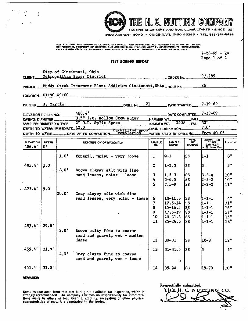
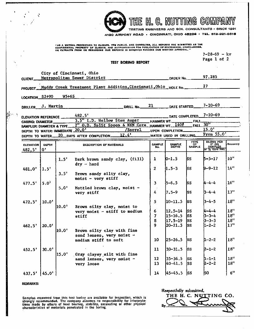
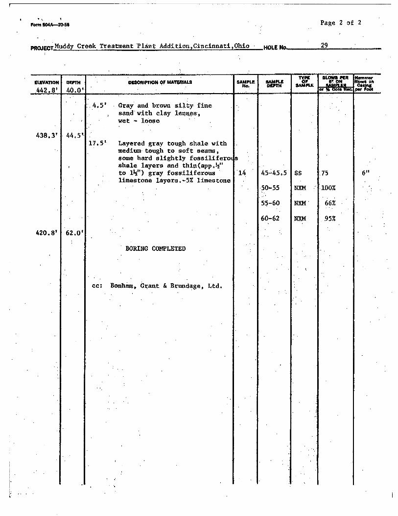
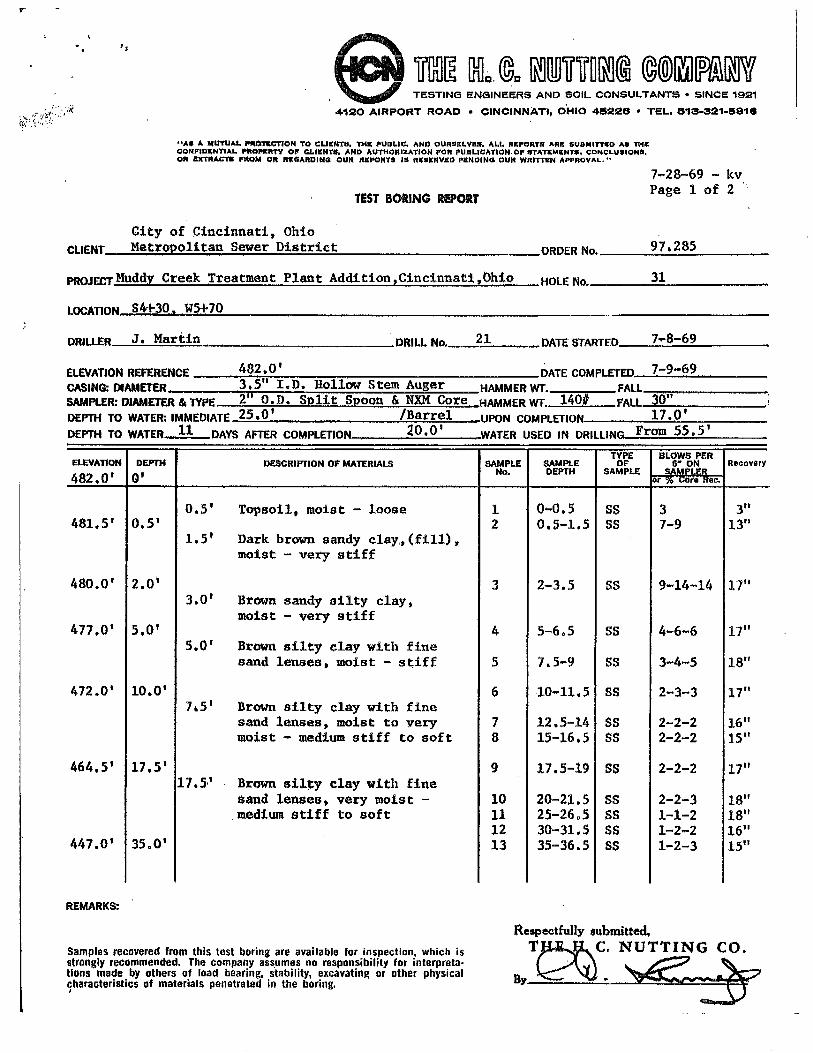
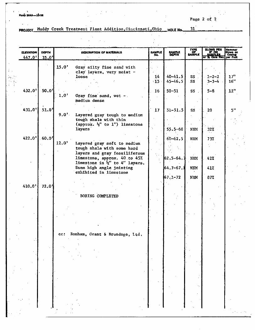
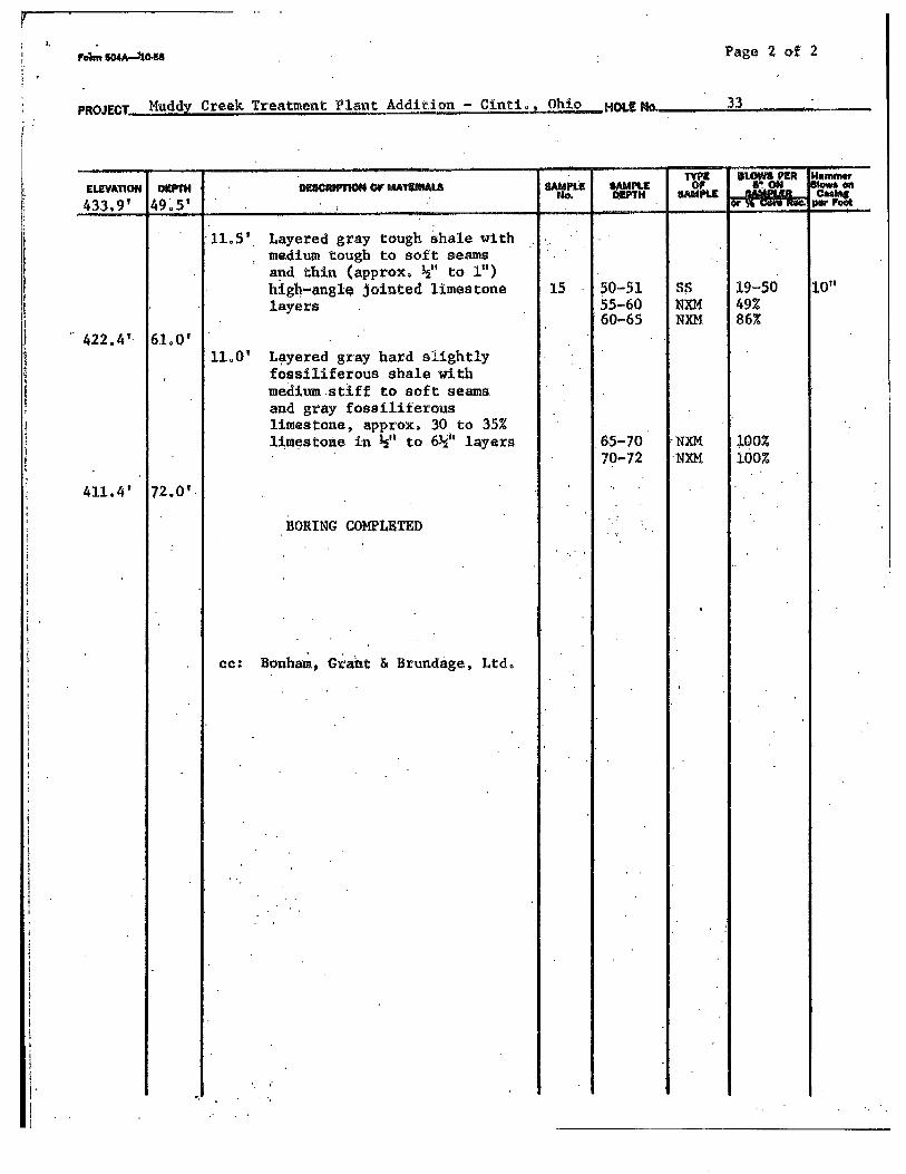
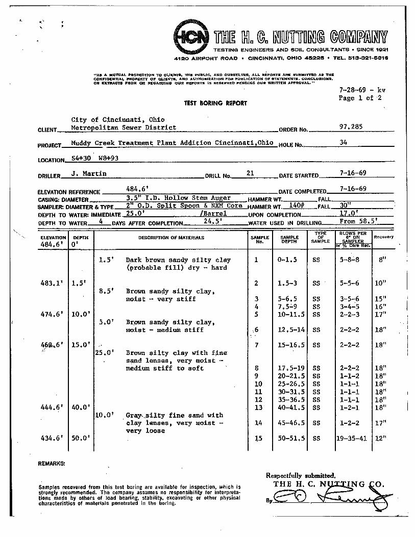
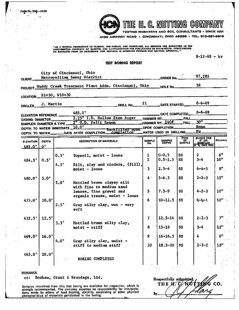
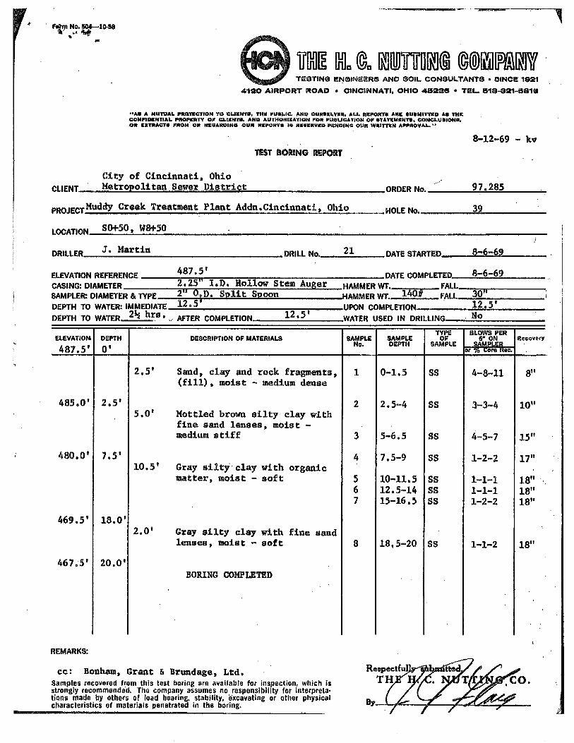
Jacobs has provided logs of Borings 22 through 39, drilled by HCN between July 7 and
August 18, 1969 for the 1971 plant addition that included the preaeration tanks.
5
However, no boring plan was made available. Based on a plant stationing system
included on a 1995 Existing Site Plan prepared by the BBS Corporation, Borings 22
through 39 appear to be located within the limits of the aeration tank, secondary settling
tank, chlorine contact tank, sludge concentration building, and secondary clarifier areas,
all located northwest of the proposed grit removal facility location. These borings
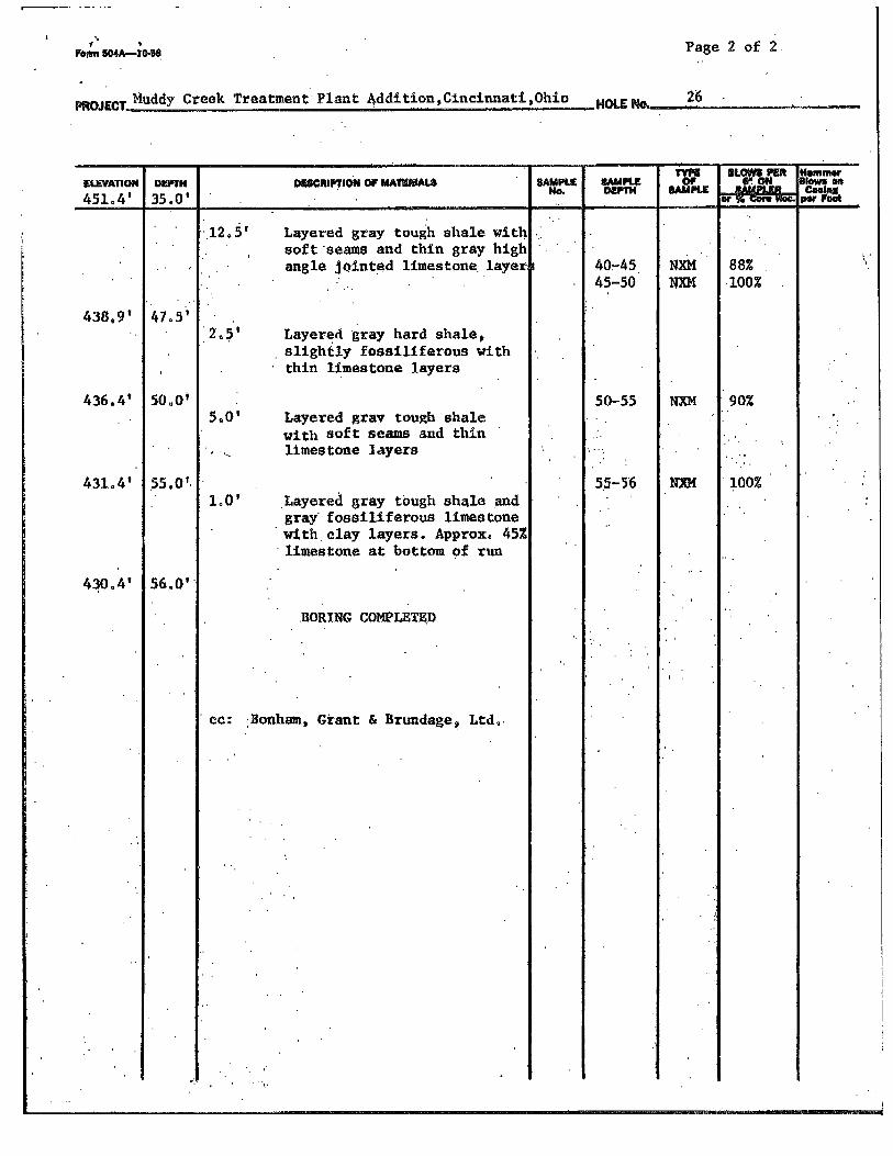
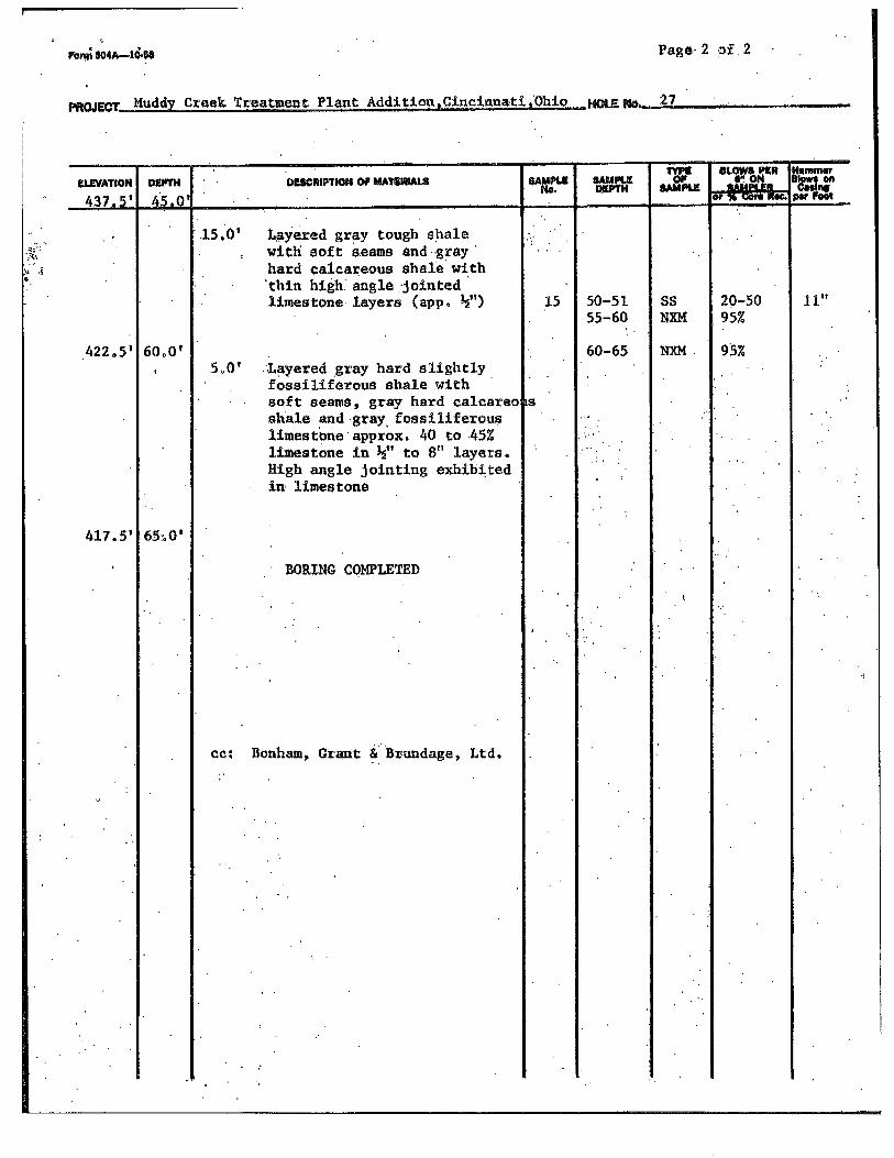
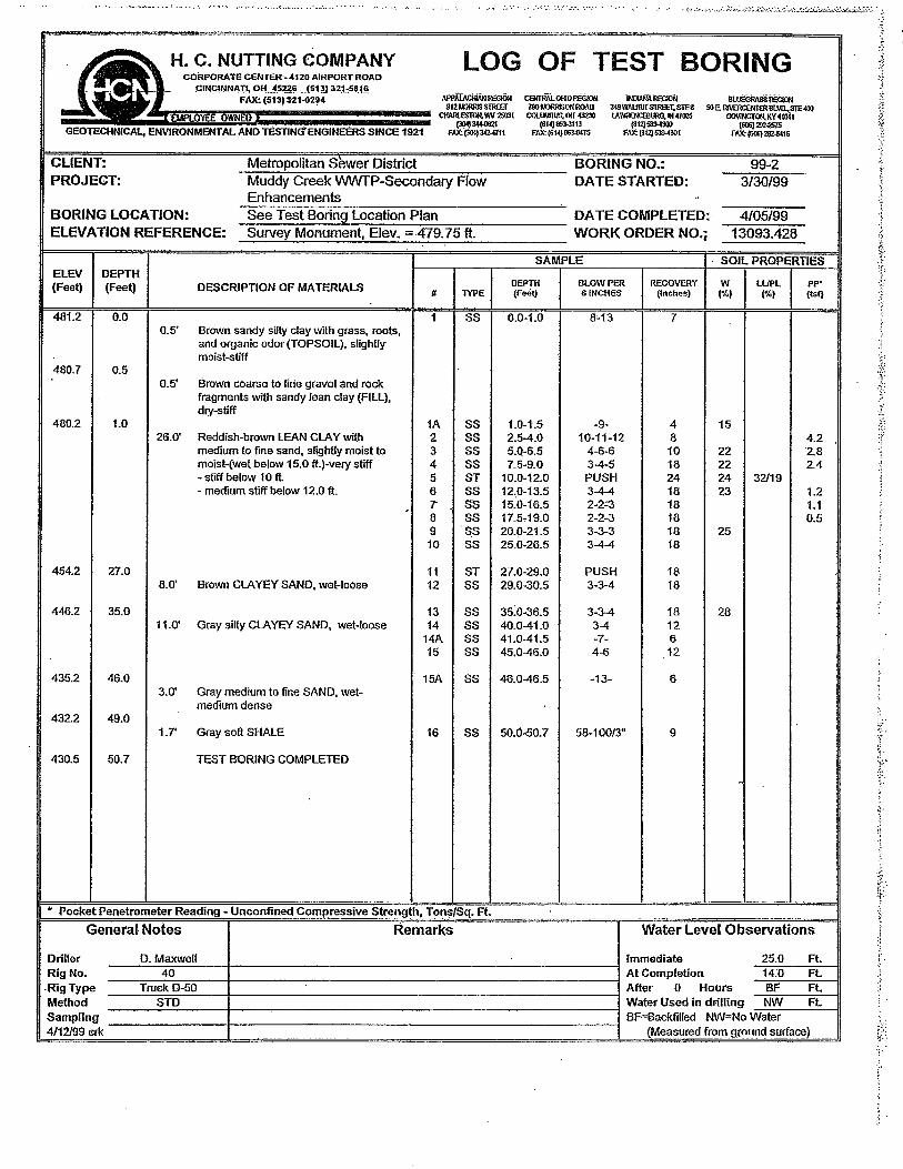
indicate that the bedrock surface varies from El. 451.4 feet in the secondary settling
tank area (Boring 26, S1+90, W9+00) to El. 431.0 feet in the sludge concentration
building area (Boring 31, S4+30, W5+70). The bedrock surface appears to be dipping
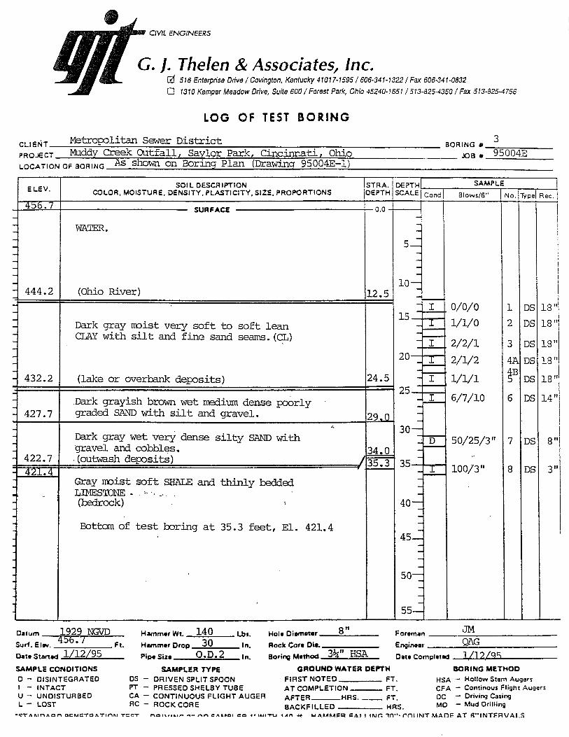
to the southeast. Thelen Boring 95004E-3, drilled in the Ohio River southwest of the
new grit facility removal location, encountered the bedrock surface at El. 422.7 feet,
indicating that the bedrock elevation continues to slope downwards to the south and
southeast beyond the preaeration tank areas. These bedrock surface elevations in the
borings appear to be consistent with the preaeration tank pile tip elevations, which
generally varied from Els. 428 to 433 feet.
The test boring logs are included in the report Appendix. A Soil Classification Sheet is
also included, which describes the terms and symbols used on the Thelen log.
The test borings indicate that the overburden soils above the bedrock generally consist
of combinations of brown and gray, moist to very moist, soft to very stiff, silty clay and
sandy, silty clay with fine sand lenses; gray, very moist, very loose, clayey silt with fine
sand lenses; brown and gray, wet, loose to medium dense, silty and clayey, fine to
coarse sand and gravel; and gray, wet, very loose to dense, silty fine sand with cobbles.
SPT „N‟ values in the cohesive soils ranged from 2 to 28 blows/foot. SPT „N‟ values in
the noncohesive soils ranged from 2 to 69 blows/foot. The cohesive soils included man-
placed site fill ranging in thickness from 1.5 to 19.5 feet.
Free subsurface water was noted in the borings during drilling at elevations ranging
from 449.6 to 475.0 feet, and at completion at elevations ranging from 465.0 to 479.4
feet. Free subsurface water levels varied from Els. 460.1 to 478.2 feet at times ranging
from 2.5 hours to 20 days following the completion of drilling.

6
CONCLUSIONS AND RECOMMENDATIONS
The conclusions and recommendations of this report have been derived by relating the
general principles of the discipline of Geotechnical Engineering to the proposed
construction outlined by the Project Description section of this report. Because changes
in surface, subsurface, climatic, and economic conditions can occur with time and
location, we recommend for our mutual interest that the use of this report be restricted
to this specific Grit Removal Facility project.
Our understanding of the proposed construction is based on a series of emails
exchanged between the writer, Ms. Debbie Schafer, P.E. of Jacobs Engineering Group,
Inc., and Mr. Michael R. Patterson, P.E. of Jacobs Engineering Group, Inc.; and also on
our review of specific plan sheets described in the Project Description section of this
report. We recommend that our office be retained to review the final design documents,
plans, and specifications to assess any impact that changes, additions, or revisions in
these documents may have on the conclusions and recommendations of this report.
Any changes or modifications that are made in the field during the construction phase
that alter site grading, structure location, infrastructure, or other related site work should
be reviewed by our office prior to their implementation.
If conditions are encountered in the field during construction that vary from the facts of
this report, we recommend that our office be contacted immediately to review the
changed conditions in the field and to make appropriate recommendations.
The scope of our services did not include any environmental assessment or
investigation for the presence or absence of wetlands or hazardous or toxic materials in
the soil, bedrock, surface water, groundwater or air, on or below or around this site.
We reviewed available test boring logs for our evaluation of the site conditions and for
the formulation of the conclusions and recommendations of this report. We assume no
responsibility for the interpretation or extrapolation of the information by others.
7
Based on our engineering reconnaissance of the site, the available test boring logs and
pile driving records, our understanding of the existing and proposed construction, and
our experience as Consulting Soil and Foundation Engineers in the Greater Cincinnati
Area, we have reached the following conclusions and make the following
recommendations.
Subsurface Conditions and Seismicity
1. The available test borings define a subsurface profile consisting of very stiff, silty
clay fill soils underlain by stiff to very stiff, silty clay native soils; soft to medium
stiff, silty clay native soils; loose to medium dense, silty fine sands; and the shale
and limestone bedrock. Free subsurface water levels varied from Els. 460.1 to
478.2 feet at times ranging from 2.5 hours to 20 days following the completion of
drilling.
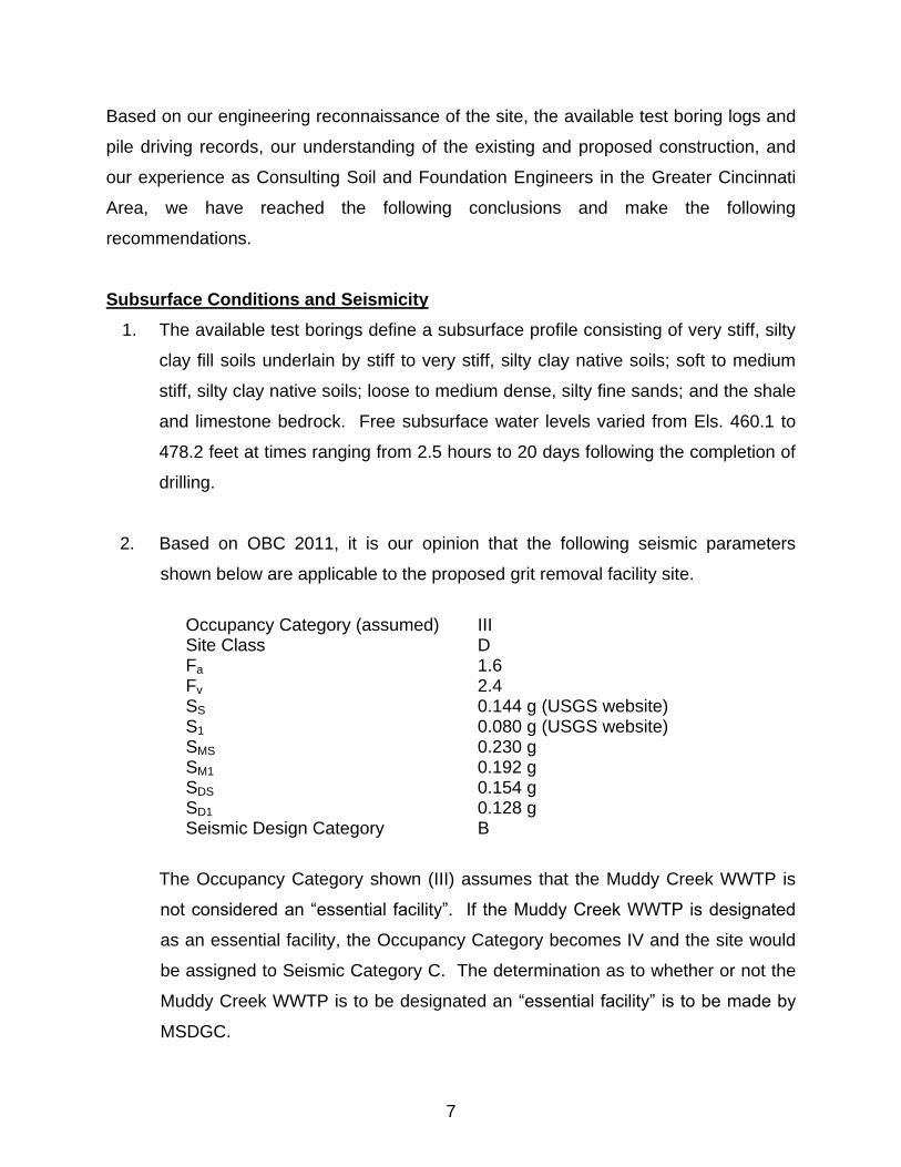
2. Based on OBC 2011, it is our opinion that the following seismic parameters
shown below are applicable to the proposed grit removal facility site.
Occupancy Category (assumed) III Site Class D Fa 1.6 Fv 2.4 SS 0.144 g (USGS website) S1 0.080 g (USGS website) SMS 0.230 g SM1 0.192 g SDS 0.154 g SD1 0.128 g Seismic Design Category B
The Occupancy Category shown (III) assumes that the Muddy Creek WWTP is
not considered an “essential facility”. If the Muddy Creek WWTP is designated
as an essential facility, the Occupancy Category becomes IV and the site would
be assigned to Seismic Category C. The determination as to whether or not the
Muddy Creek WWTP is to be designated an “essential facility” is to be made by
MSDGC.

8
Existing Pile Capacity
3. The piles in the preaeration tanks were required to have respective minimum
allowable compressive and uplift capacities of 25 and 15 tons, and respective
minimum ultimate compressive and uplift capacities of 50 and 30 tons. However,
the Contractor was only required to load them to twice the design load, or 50 tons
compression / 30 tons tension. Because the Contractor was not required to load
the test piles to failure, we can only assume that the piles were successfully
tested to a compressive load of 50 tons and to an uplift load of 30 tons. The
ultimate capacities of the piles may be greater, but the load tests were not
required to show how much greater.
4. The weights of steel reinforcement indicated on the pile driving records suggest
that each pile was constructed with a full-depth, steel reinforcing cage, which
would appear to exceed the pile design requirements shown on Sheet 20 (Piling
Plan and Details). However, this may have been done to gain the required
ultimate pile capacities with a smaller-diameter pile.
5. Comparison of the pile tip elevations with the HCN boring logs indicates that the
piles were driven to refusal on or slightly below the bedrock surface. The piles
were driven with a Link Belt 440 hammer, which has a rated energy of 18,200 ft-
lb. The piles were driven to their final penetrations at rates of at least 16
blows/inch. A simple analysis indicates that piles driven with that rated energy
and at those final penetration rates may have ultimate capacities of about 120
tons. Applying a safety factor of 3.0, which is appropriate when load test data
are not available, would yield an allowable compressive capacity of 40 tons.
6. Based on the pile driving records, the hammer rating, and the presence of the
shale and limestone bedrock, it is our opinion that the existing piles have higher
ultimate compressive capacities than 50 tons, even if they are 12-inch-diameter
piles. However, regardless of the actual pile diameter, Section 1810.3.3.1.1 of
OBC 2011 limits driven piles to allowable compressive capacities of 40 tons in
the absence of load test data.

9
7. In our opinion, the existing piles may be utilized for allowable compressive loads
of 40 tons and for allowable uplift loads of 15 tons. If higher capacities are
desired, load testing will be necessary as per Section 1810.3.3.1.1 of OBC 2011.
8. Dynamic, non-destructive load testing may be performed on any of the existing
piles that can be exposed for testing. Dynamic pile testing would require that the
pile be exposed by removing a portion of the existing concrete slab, cutting off
the existing hook bar dowels, and excavating about 2 feet of soil from around the
pile so that testing gauges can be attached. The testing could then be completed
using a portable, low-headroom, hydraulic impact hammer such as the American
Piledriving Equipment, Inc. (APE) Model 7.5c or approved equivalent. This
hammer can be lifted and moved using a forklift; both the hammer and forklift
would need to be lowered into the existing tank with a crane. The APE Model
7.5c has a maximum rated energy of 15,200 ft-lb.
9. Assuming that the pile layout shown on Sheet 20 is correct, the largest area
supported by any existing pile within the proposed concrete infill area of
Preaeration Tank No. 2 is 32.5 ft2 (6.29 ft X 5.17 ft). The maximum fill height is
18.25 feet, assuming that the area is to be filled to the top of the wall. This would
impose a maximum load of 44.5 tons on the most widely-spaced piles along the
southeast tank edge; this exceeds the maximum allowable compression load by
a little over 11 percent. Options are to a) use a lightweight concrete fill product
that would need to have a density at or below 135 pounds per cubic foot (pcf); b)
backfill the area with compacted and tested fill; or c) limit the height of concrete
backfill in the tank such that the 40-ton allowable compressive load will not be
exceeded.
Other Considerations
10. The concrete infill in Preaeration Tank No. 2 will need to be placed in lifts to
avoid overstressing the central wall that separates the tanks.
11. If compacted and tested fill is used to backfill the proposed infill area of
Preaeration Tank No. 2, we recommend that it meet the requirements of

10
structural fill. Clayey fill should be placed in maximum 12-inch lifts, and should
be compacted with appropriate equipment to at least 95 percent of the maximum
dry density obtained by the standard Proctor moisture-density test (ASTM D698),
at moisture contents within 3 percent of the optimum moisture content. Granular
fill should be placed in maximum 8-inch lifts, and should be compacted with
appropriate equipment to at least 75 percent relative density as per the ASTM
D4253/D4254 Test Methods. Fill materials should not include trash, debris,
organic matter, frozen materials, or any other deleterious materials.
12. If clayey backfill is used, we recommend that a manufactured drainage mat be
placed against the tank walls prior to backfill placement. The drainage mat
should extend no higher than 24 inches below the top of the fill. The base of the
mat should be hydraulically connected to a minimum 4-inch-diameter, rigid,
perforated (perforations down), PVC pipe connected to a sump or gravity outlet.
The pipe should be surrounded by at least 6 inches of free-draining, granular fill
containing no more than 3 percent fines. A filtration geotextile such as Mirafi
140N (or approved equivalent) should separate granular fill materials from any
clayey backfill to prevent migration of fines into the drain.
13. If granular backfill is used, the manufactured drainage mat will not be necessary
as long as the fill material is free draining (i.e., contains less than 3 percent
fines). The granular fill will still require permanent drainage.
14. A November 4, 2011 e-mail from Mr. Patterson notes that Sheet 20 called for 230
piles, while the driving records indicate that 233 piles were installed. The writer‟s
review of the pile driving records indicate that only 230 of the piles were included
in the final pay length quantity, suggesting that perhaps the three extra piles were
rejected for some reason.

APPENDIX
ASFE Report Information
Boring Plan, Drawing No. 110187E-1
HCN Test Boring Logs
Thelen Test Boring Logs, Project No. 95004E
Soil Classification Sheet


95004E-1
95004E-3
(422.7)
39
22
23
(439.6)
24
(439.1)
26
(451.4)
27
(437.5)
28
(438.7)
30
(449.1)
29
(438.3)
31
(431.0)
32
(432.6)
33
(433.9)
34
(434.6)
3536
37
38
HCN 99-2
(432.2)
HCN 97-1
PROPOSED GRIT
REMOVAL FACILITY
LOCATION
270' (N
.T
.S
.)
HCN 99-1
(430.9)
Scale:
Date:
Drawing No.:
Title:Project:
Client:
Location:
Notes
1398 Cox Avenue, Erlanger, Kentucky 41018 / 859-746-9400Lexington, Kentucky • Cincinnati, Ohio • Dayton, Ohio
BORING PLAN
BASE MAP TAKEN FROM SITE PIPING PLAN, SHEET CU-101,
BY JORDAN, JONES & GOULDING, DATED FEBRUARY 2011
Jacobs Engineering Group, Inc.
Consulting Services
MSDGC Muddy Creek WWTP
Grit Removal Facility
Sayler Park, Ohio
1" = 100'
1/31/2013
110187E-1
INDICATES THELEN TEST BORING (PROJECT NO. 95004E)
INDICATES HCN TEST BORING LOCATIONS
INDICATES BEDROCK SURFACE ELEVATION (FT.)
(439.1)