Contact creep compliance of viscoelastic materialsvia nanoindentation
Catherine A. Tweedie and Krystyn J. Van Vlieta)
Department of Materials Science and Engineering, Massachusetts Institute of Technology,Cambridge, Massachusetts 02139
(Received 5 August 2005; accepted 22 March 2006)
The creep compliance of viscoelastic materials such as synthetic polymers is anestablished metric of the rate at which strain increases for a constant applied stress andcan, in principle, be implemented at the nanoscale to compare quantitatively bulk orthin film polymers of different structures or processing histories. Here, we outline theevolution of contact creep compliance analysis and application for both conical andspherical indenter geometries. Through systematic experiments on four amorphous(glassy) polymers, two semi-crystalline polymers and two epoxies, we show thatassumptions of linear viscoelasticity are not maintained for any of these polymerswhen creep compliance is measured via conical indentation at the nanoscale, regardlessof the rate of stress application (step or ramp). Further, we show that theseassumptions can be maintained to evaluate the contact creep compliance Jc(t) of thesebulk polymers, regardless of the rate of stress application, provided that the contactstrains are reduced sufficiently through spherical indentation. Finally, we consider thestructural and physical properties of these polymers in relation to Jc(t), anddemonstrate that Jc(t) correlates positively with molecular weight betweenentanglements or crosslinks of bulk, glassy polymers.
I. INTRODUCTION
Devices composed of small volumes of time-dependent materials, such as polymeric thin films, hy-drated biological scaffolds, and microelectronic packag-ing, require mechanical characterization not attainablethrough well-developed methods suitable for bulk mate-rials. Several categories of nanomechanical testing exist,including quasistatic nanoindentation,1 dynamic nanoin-dentation,2,3 nanomechanical contact creep,4–10 and im-pulse indentation.11 However, few analytical methods tointerpret time-dependent material responses have beenproposed that do not assume the material to be well-described as a linear viscoelastic solid. Despite frequentapplication of this assumption, this idealized response isnot maintained in most nanomechanical experimentalconditions on polymers, and this assumption can thuspropagate quantitative and qualitative errors in analysisof polymer deformation. Time-dependent materials willbehave as linear viscoelastic solids below a material-dependent, limiting elastic strain on the order of 1–2%.Stress, and thus strain, imposed on the material under
contact loading such as nanoindentation may be reducedby decreasing the magnitude of the applied force P or byincreasing the area over which P acts on the material.However, most instrumented nanoindenters have a fixedload range over which data can be acquired accurately,such that the indenter geometry and corresponding shapefunction are important experimental factors.
Nanomechanical creep testing has significant potentialfor interpreting the mechanical responses of polymersbecause the material response inherently includes time-dependent deformation. The shear creep compliance J(t)is strictly defined as the change in strain as a functionof time under instantaneous application of a constantstress, or
J�t� =��t�
�o, (1)
and provides a means to quantify the capacity of a ma-terial to flow in response to a sudden applied stress.12
Although conventional measurements of J(t) includeduniaxial or simple shear stress, researchers have increas-ingly reported creep compliance interpretations of instru-mented (conical and spherical) indentation experimentson bulk or thin film polymers. However, due to the non-linearities in material behavior and contact mechanics,current experimental investigations of creep compliance
a)Address all correspondence to this author.e-mail: [email protected]
typically assume particular linear viscoelastic models tofit the creep response. Figure 1 schematically illustratesthe linear viscoelastic creep response at various appliedstresses. The doubling of the instantaneous and constantapplied stress �1 exactly doubles the strain �(t) for anytime t during creep [Fig. 1(a)]. It is well-established thatthe creep compliance J(t) for a linear viscoelastic mate-rial is invariant with applied stress [Fig. 1(b)] due to thelinear relationship between stress and strain at any timepoint for such materials. Referencing Eq. (1), a polymer
for which J(t) changes as a function of maximum instan-taneous stress � does not conform to the assumptions oflinear viscoelasticity. That is, J(t)/�(t) � k where k is aconstant, due to the nonlinear constitutive relations ofthat particular polymer and/or to induced strain in excessof the linear viscoelastic strain limit for that material. Ineither case, polymers that do not exhibit J(t)/�(t) � k fora given indenter geometry and load/stress range cannotbe characterized accurately by models that implicitly as-sume a purely linear viscoelastic response. Further, themodels from which most expressions for creep compli-ance J(t) expressions are derived were developed to de-termine the pressure distribution for axisymmetric in-denter contact on viscoelastic solids12,13 and simplifiedfor the case of step loading. In actuality, few nanome-chanical instruments can attain the step-load conditionbecause of limitations in speed of data acquisition and inforce resolution. Thus, “quasi-step” loading, where theminimum loading time documented thus far for the step-load experiment is 1 s,5,6,14 is often used. Loading ratehas been demonstrated to have an effect on the creepresponse,5,9 and corrections for ramp loading have beenproposed for a specific linear viscoelastic constitutiverelation.10
In attempts to attain the linear viscoelastic deformationregime during indentation-enabled creep, several studieshave included rounded conical probes (R � 10 and20 �m,6,14,15) and spherical probes (R � 3.4 �m5 to150 �m10). However, it is not generally considered ordemonstrated whether polymers conform to the idealizedlinear viscoelastic response of Fig. 1(b) under the contactcreep conditions used, with notable exceptions.7,10 Often,Jc(t) is evaluated among polymers for only a singlePmax,9,14 such that load dependence cannot be ruled out.Lu et al. posited that, because indentations below a criti-cal indentation depth (unique to each of two amorphouspolymers considered) were not observable post-indentation via scanning electron microscopy, recoveryimplied linear viscoelasticity.5 However, such indenta-tion recovery does not ensure a linear path in either load-ing or unloading; linear viscoelastic deformation of thesematerials under indentation was neither proved nor dis-proved. Recent approaches to determination of Jc(t) orlinear viscoelastic operators based on the contact creepresponse are summarized in Sec. II. C, including thosethat also consider the limits of a linear viscoelastic creepresponse. As Jc(t) is often interpreted within the frame-work of phenomenological models of linear viscoelasticbehavior, for which there can be several distinct formsthat reasonably fit a measured contact creep response, itis useful to also consider how Jc(t) can be related to thestructure and physical properties of polymers.
The contact creep compliance Jc(t) is calculated hereinprimarily to demonstrate when the implicit assumption oflinear viscoelastic deformation is obtained experimentally
FIG. 1. (a) Ideal linear viscoelastic behavior is illustrated as strain � asa function of time during creep tc for three instantaneous and constantlevels of applied stress �i. (b) Creep compliance J(t) for a linearviscoelastic material is characteristic of that material and independentof �i.
C.A. Tweedie et al.: Contact creep compliance of viscoelastic materials via nanoindentation
J. Mater. Res., Vol. 21, No. 6, Jun 2006 1577
and to consider how the material response changes withboth polymer/monomer structure and loading conditions.Creep compliance formulations for conical and sphericalindenter geometries are outlined and compared, and re-cent extensions are discussed. The contact creep compli-ance of eight bulk (semicrystalline and amorphous) poly-mers is then characterized with a Berkovich indenter thatcan be approximated as a conical geometry; none of thepolymers behave as linear viscoelastic materials underthese conditions. In contrast, the creep compliance of asubset of these same polymers under the same creeploads exhibits linear viscoelastic behavior for a sphericalindenter of R � 500 �m. These results illustrate the limitof linear viscoelastic analyses in nanomechanical creepcompliance characterization and also demonstrate therelative effects of monomer structure, molecular sterichindrance, and microstructure on the contact creep com-pliance of bulk polymers.
II. BASIS AND IMPLEMENTATION OF CONTACTCREEP COMPLIANCE SOLUTIONS
As demonstrated below, although the conditions re-quired for accurate creep compliance determination ac-cording to Eq. (1) are typically not maintained in inden-tation-enabled creep experiments, this characterization oftime-dependent flow can be used to compare materialsand/or consider the microstructural determinants of poly-mer deformation. For this reason, we delineate creepmeasured via instrumented indentation as contact creepcompliance Jc(t), underscoring the fact that load and notstress is maintained constant in such experiments. Themajority of viscoelastic solutions used to interpret con-tact creep compliance derive from two independently ob-tained derivations to the general problem of contact be-tween a rigid symmetric body and a viscoelastic half-space. These solutions for creep compliance in shear J(t),reported by Lee and Radok (1960) and by Ting (1966),were elegant responses to an analytical challenge: vis-coelastic deformation for which the Laplace transformcould not be readily applied to predict stress distributionsunder contact loading (see Appendix A). Here, we statethe relevant solutions of Lee and Radok (LR-) and Ting(T-), and summarize recent implementation in experi-mental investigations of creep for bulk and thin filmpolymers.
A. Solutions for spherical indenter geometry
The LR-solution for creep compliance in shear underspherical indentation where a � R under a constant ap-plied load Po can be stated as
Jc�t� = �1 − ��J�t� =8�R
3Po�h�t��3�2� , (2)
whereas the T-solution for the same condition can bestated as
��t� =8�R
3Po�h�t��3�2� , (3)
such that �(t) � (1 – �)J(t) for constant �, or �(t) �1/2J(t) for incompressible materials for which � � 1/2.Ting states that �(t) is of the general form of creep com-pliance but does not explicitly equate �(t) to Jc(t). Nei-ther solution of the pressure distribution actually requiresstep-loading of the viscoelastic material, but both solu-tions are simplified by this constraint and implicit in therepresentations of Jc(t) for Eqs. (2) and (3).
B. Solutions for conical indenter geometry
Lee and Radok did not consider conical indenter ge-ometries, presumably due to the constraint of “smallstrains” imposed by linear viscoelastic operators. How-ever, Ting presented a general solution for any smooth,axisymmetric indenter profile and provided specific so-lutions of total contact pressure for conical, spherical,and paraboloidal (classic sphere for a � R) geometries.The T-solution for �(t) � 1/2J(t) � Jc(t) under an in-stantaneously applied and constant depth ho is generallygiven by Eq. (A11) of Appendix A. For a conical in-denter of semi-apex angle � /2 – �, where � is theangle between the material free surface and inclined in-denter surface assumed by Ting, contact creep compli-ance Jc(t) is
Jc�t� =2a2�t = 0�tan�
P�t�. (4)
For the case more accessible to instrumented indenta-tion experiments, an instantaneously applied and con-stant force Po,
Jc�t� =2a2�t�tan�
Po=
8tan��h2�t�
Po. (5)
As stated in Eq. (5), Jc(t) can be calculated directlyfrom experimentally measured h(t) for a known indentersemi-apex angle . Although this calculation is straight-forward and the average contact stress for a conical in-denter is maintained constant by virtue of the self-similargeometry, the stress singularity at the cone apex imme-diately violates the assumption of linear (or small strain)viscoelastic deformation.
Equations (2)–(5) represent the principal relations fordetermining creep compliance from contact loading, i.e.,indentation-enabled creep experiments. Equations (3)and (5) are used to analyze the experiments in the presentstudy. These equations assume linear viscoelasticity butdo not assume any particular form of the constitutiverelation in terms of the nature of the linear viscoelastic
C.A. Tweedie et al.: Contact creep compliance of viscoelastic materials via nanoindentation
J. Mater. Res., Vol. 21, No. 6, Jun 20061578
operators. More simply, these solutions do not presup-pose configurations of springs and dashpot elements thatdescribe phenomenologically the stress or strain of a realpolymer at short and long times. However, both Lee andRadok13 and Ting12 illustrate an application for indenta-tion of a Maxwell solid. Ting thus shows that a decreasein applied load need not result in a decrease in contactarea for a conical indenter geometry—an analytical pre-diction of the so-called “nose effect” observed duringindentation unloading of polymers under insufficientlyrapid unloading rates.16,17
C. Extensions and applications of Jc(t) models
Here, we briefly outline the extensions and adaptationsof these solutions by others who have subsequently de-termined Jc(t) via indentation for specific polymers andloading conditions. First, we consider approaches that donot assume a particular form of the linear viscoelasticoperators and compare polymer response directly on thebasis of measured Jc(t).
5,7 Next, we consider approachesthat inherently assume a spring-dashpot constitutive re-sponse of the polymer (such as the standard linear solidmodel6,9,10,14,18) from which model-dependent constantscan be obtained.9,10,14 As discussed, it is possible to dem-onstrate whether the condition of linear viscoelastic de-formation is met with either approach.
Lu et al. adapted the solutions of Sneddon,19 Ting,12
and Lee and Radok13 to extract viscoelastic propertiesfrom contact creep experiments via spherical and conicalindenter geometries.5 The authors found less than 10%error of Jc(t) calculated during quasi-step loading withconical or spherical indenters [for amorphous poly-(methyl methacrylate) (PMMA) and polycarbonate(PC)], in contrast to J(t) measured in separate experi-ments via conventional uniaxial (PMMA) or shear (PC)creep compliance measurements. However, the contactcreep conditions were not demonstrated to be indepen-dent of creep load Po. In contrast, Van Landinghamet al.7 have recently applied Ting’s solution for a con-stant applied load Po to compute Jc(t) for amorphous(glassy) polymers and epoxies under conical indentation-enabled creep experiments. The authors superposed a cy-clic load during a dwelling period at each of severaldistinct Po to obtain the projected contact area Ac(t) foreach data point during the dwelling period rather thancalculate Jc(t) directly from h(t) and found that none ofthe polymers analyzed via Berkovich conical indentationand Eq. (5) were well-described as linear viscoelastic:Jc(t) was not independent of applied load.
Although Jc(t) can be determined quantitatively with-out recourse to a particular linear viscoelastic constitu-tive relations via Eqs. (2)–(5), the experimentally ob-served h(t) can also be fit to a particular form of the creepfunction. Yang et al.9 did not consider the elastic or
viscoelastic contact solutions rigorously but rather ap-plied the constitutive relations for a Kelvin-type solid (aseries of parallelized springs Ei and and dashpots �i ofestablished �-� relations) to a flat punch to determine h(t)and thus
J�t� =h�t�
�ohin= �
i
Ji , (6)
where hin is an empirically determined length scale, andthe form of Ji represents the number of Kelvin-type el-ements in series that exhibit the characteristic depth de-cay of (1 − et/
i). The authors considered several amor-phous polymers but could not correlate known physicalor monomer structure/properties with the creep compli-ance quantified in this way. In contrast, Cheng et al.14
and Oyen10 adapted the Lee and Radok-solution to in-terpret spherical indentation creep on the basis of a stan-dard linear solid model (i.e., a spring in series with aKelvin–Voigt parallel spring and dashpot), via themethod of Laplace transforms5,14 or direct solution of theviscoelastic integral equations.10 Defining Jc(t) in termsof a constitutive model enables tractable solutions ofconstants defined by the model, but it is well understoodthat the number and magnitude of linear operators (orProny series constants) is not unique and that severalsuch sets can accurately describe a measured creep re-sponse. The resulting constants or material properties ex-tracted from these fits necessarily depend on both thematerial and the form of the constitutive model that de-fines the creep function. Within a given study assuminga specific model, results among polymers can be com-pared, but it is then difficult to compare among studies orinterpret Jc(t) as a function of the structure and physicalproperties of these polymers. Cheng et al. described Jc(t)generally as
Jc�t� = �i=1
N
Jie−t� i , (7)
where constants were determined through fits to experi-mental data and represented rather involved algebraicfunctions of the simple linear solid constitutive relationsfrom which element constants E1, E2, and � could ulti-mately be determined. The authors found that the inden-tation elastic modulus Ei agreed well with E1 extractedfrom the creep-type experiments for amorphous polysty-rene and semicrystalline polymer poly(vinyl alcohol) atvery low relative humidity (10%) but disagreed signifi-cantly at higher relative humidity, attributing this dis-crepancy in part to increased viscoelasticity under higherhumidity. Oyen tested the applicability of the standardlinear solid model to several polymer films by fitting adifferent linear viscoelastic creep function for a sphericalindenter geometry (R � 150 �m) under single-ramp and
C.A. Tweedie et al.: Contact creep compliance of viscoelastic materials via nanoindentation
J. Mater. Res., Vol. 21, No. 6, Jun 2006 1579
multi-step ramp loading to extract associated time con-stants and instantaneous shear modulus G.10 Successfulprediction of h(t) was demonstrated for an order of mag-nitude increase in loading time (20 to 200 s) and a factorof two increase in maximum load (50 to 100 mN), indi-cating that this linear viscoelastic material model couldbe applied to contact creep analysis under specific (load-ing and environmental) conditions. That is, rather thanshowing that measured Jc(t) was independent of load, theauthor demonstrated additivity required of linear vis-coelasticity: the creep function form accurately predictedthe h(t) response measured at multiple creep loads.10
In the present study, we sought to determine the ex-perimental conditions under which the assumptions im-plicit in Eqs. (2)–(5) hold, such that Jc(t) can be meas-ured within the linear viscoelastic regime. Further, ratherthan fit Jc(t) to a particular linear viscoelastic constitutivemodel, we considered Jc(t) as it relates to the molecularstructure and physical properties of a range of well-characterized bulk polymers.
III. EXPERIMENTS
A. Materials
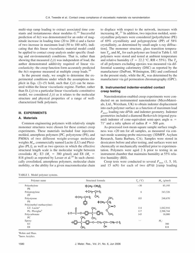
Common engineering polymers with relatively simplemonomer structures were chosen for these contact creepexperiments. These materials included four injection-molded, amorphous polymers [PC, polystyrene (PS), andPMMA of two different weight-average molecularweights Mw, commercially named Lucite (LU) and Plexi-glas (PL)], as well as two epoxies in which the effectivestructural length scale is the molecular weight betweencrosslinks Mc: E3 (Mc � 380 g/mol) and E8 (Mc �818 g/mol) as reported by Lesser et al.20 In such chemi-cally crosslinked, amorphous polymers, molecular chainmobility, or the ability for a given macromolecular chain
to displace with respect to the network, increases withincreasing Mc.
21 In addition, two injection molded, semi-crystalline polymers were considered [polyethylene (PE)of 69% crystallinity and polypropylene (PP) of 58%crystallinity, as determined by small-angle x-ray diffrac-tion]. The monomer structure, glass transition tempera-ture Tg, and Mw for each polymer are listed in Table I. Allpolymers were stored and tested at ambient temperatureand relative humidity (T � 22.2 °C, RH < 55%). The Tg
of all polymers excluding epoxies was measured via dif-ferential scanning calorimetry (DSC) as reported by themanufacturer (DuPont, Wilmington, DE) and confirmedin the present study, while the Mw was determined by themanufacturer via gel permeation chromatography (GPC).
B. Instrumented indenter-enabled contactcreep testing
Nanoindentation-enabled creep experiments were con-ducted on an instrumented nanoindenter (MicroMateri-als, Ltd., Wrexham, UK) to obtain indenter displacementinto each polymer surface as a function of maximum loadPmax, loading rate dP/dt, and indenter geometry. Indentergeometries included a diamond Berkovich (trigonal pyra-mid) indenter of cone-equivalent semi-apex angle �71° and a ruby sphere of radius R � 500 �m.
As-processed root-mean-square sample surface rough-ness was <20 nm for all samples, as measured via con-tact-mode scanning-probe microscopy (3DMFP, AsylumResearch, Santa Barbara, CA). Samples were stored indessicators before and after testing, and surfaces were notchemically or mechanically modified prior to experimen-tation. Polymers were aged 2 h prior to testing in aninstrument chamber that maintains humidity at 55% rela-tive humidity (RH).
Creep tests were conducted to several Pmax (1, 5, 10,and 15 mN) for each of two dP/dt [ramp loading
TABLE I. Model polymer systems.
Polymer name Structural formula Tg (°C) Mw (g/mol)
C.A. Tweedie et al.: Contact creep compliance of viscoelastic materials via nanoindentation
J. Mater. Res., Vol. 21, No. 6, Jun 20061580
(0.5 mN/s) and rapid “quasi-step” loading (0.5 s toPmax)], as well as to Pmax � 30 mN for ramp loadingonly. The quasi-step loading over a constant elapsed timerequired variation of loading rates to ensure sufficientdata point acquisition at increased speeds (2, 10, 20, and30 mN/s). For each pair (Pmax, dP/dt), constant load Pmax
� Po was maintained for 10, 60, or 100 s to acquire h(t).During this holding period approximating creep condi-tions, P did not vary more than 2%; for “quasi-step”loads, the overshoot of the desired Po did not exceed 10%for the range of polymers considered. Indentation depthsranged between 300 and 2500 nm for experiments withthe Berkovich indenter geometry and between 50 and300 nm for the spherical indenter geometry. Typical driftin the displacement signal at room temperature is 0.01nm/s. Each sample was tested at least in triplicate foreach loading condition for the Berkovich indenter geom-etry. The two epoxy samples were tested in triplicate toall loading conditions with both the Berkovich andspherical indenter geometries. Equation (3) or (5), asappropriate for the indenter geometry used, was fit to theacquired h(t) response, where tc is the elapsed time afterattainment of the maximum contact load Po via step orramp loading; that is, both step and ramp loading creepwere evaluated from h(tc � 0).
IV. RESULTS AND DISCUSSION
A. Nanoindentation contact creep with asharp indenter
1. Nonlinear viscoelastic deformation
Eight common engineering polymers, with monomerstructures and physical properties outlined in Table I,were evaluated at several distinct Pmax values with aBerkovich (sharp trigonal pyramid) indenter. The con-tact creep compliance, calculated using the model-independent formulation of Jc(t) in Eq. (5), exhibited apositive dependence on increasing Pmax for all the poly-mers tested, confirming nonlinear viscoelastic behaviorunder these contact creep conditions for structurallysimple amorphous polymers. Similar values for contactcreep compliance of polymeric materials with a Berko-vich indenter geometry were found in other recent stud-ies.9,15 Figure 2(a) shows the typical variation of Jc(t)with Po ranging from 3 to 15 mN, and Fig. 2(b) comparesall polymers for Po � 3 and 15mN at Jc(t � 10 s). Notethat in response to an increase in Pmax by a factor of five,all amorphous polymers exhibited a marked increase inJc(t) at the higher Pmax, and therefore all amorphouspolymers exhibited nonlinear viscoelastic deformationunder these conditions. Although Jc(t) can be calculatedaccording to Eq. (5), the inherent assumptions of thiscalculation are not maintained. Therefore, the data arediscussed in terms of monomer and microstructural
determinants of creep-like resistance to viscoelastoplas-tic flow in Sec. IV. C.
Plastic flow is a competing deformation mechanismunder indentation-enabled creep compliance.22,23 Oneway to assess the extent of plasticity is to subtract thecreep portion of the displacement from the loading-unloading cycle and determine the extent to which thecorrected, final depth of indentation h�f exceeds themaximum depth of indentation prior to the creep segment
FIG. 2. Contact creep compliance Jc(t) under ramp loading of 0.5 mN/svia Berkovich (sharp) probe. (a) PL shows typical dependence oncreep load for Po: 3 mN (light gray), 15 mN (dark gray) and 30 mN(black). (b) Comparison among all polymers at Jc(t � 10s) for Po: 3 mN(black) and 15 mN (gray) indicate increasing Jc(t) with decreasingsteric hindrance. Polymer abbreviations are as follows: PMMA PL,PMMA LU, PS, PC, PP, PE, and two epoxies, E3 and E8.
C.A. Tweedie et al.: Contact creep compliance of viscoelastic materials via nanoindentation
J. Mater. Res., Vol. 21, No. 6, Jun 2006 1581
hmax. The ratio h�f /hmax is proportional to the percentplastic work Wp/Wtotal.
24 We found that, for the Berko-vich indenter geometry, h�f /hmax was as great as 62% inthe amorphous polymers considered herein, indicatingthat there was indeed deformation that was not recoveredduring the unloading cycle of the indentation experiment.As we have shown via scanning probe microscopic ex-amination of post-indentation recovery of Berkovich in-dentation in these same polymers,25 although the depthof indentation does continue to recover over the next48 h post-indentation, the volume of indentation does notrecover appreciably because the material at the indentersidewalls (where two facets of the pyramid join) remainsplastically deformed over at least 48 h post-indentation.
2. Effect of loading rate dP/dt
Contact creep experiments conducted with a sharpconical indenter induce not only a load-dependent re-sponse but also a loading rate-dependent response. Thispoint is illustrated in Fig. 3(a) where Jc(t) of the low-Mc
epoxy E3 is shown for three maximum loads (Po � 1, 5,and 15 mN) for both ramp and step loading. The increasein loading rates induces an increase in Jc(t) at all Po
considered, as rapid loading to Po minimizes energy dis-sipation through viscous mechanisms, while slow load-ing to Po enables concurrent elastic and viscous re-sponses prior to creep. Figure 3(b) demonstrates the ef-fects of increased chain mobility on this loading ratedependence under conical indentation creep, comparingJc(t) for E3 (low Mc) and E8 (high Mc) for three Pmax
attained via ramp loading (dP/dt � 0.5 mN/s). As ex-pected from Fig. 2(b), the increase in Mc causes an in-crease in the Jc(t) for all conditions. Surprisingly, thepolymer of lower Mc, and thus lower molecular chainmobility, exhibits a greater dependence on load. Thisresult is consistent with the pair of amorphous polymersPC (lower Mw) and PL (greater Mw), in which case thepolymer with fewer entanglements and greater chain mo-bility (PC) is affected less by changes in load than thepolymer with less chain mobility (PL) during contactcreep. Experiments performed by Van Landingham etal.15 demonstrated the same trend for PMMA and anepoxy: creep tests were carried out between Pmax � 0.2and 10 mN on PMMA and epoxy samples (different fromthe epoxies detailed herein). Although the epoxy wasslightly stiffer than the PMMA upon loading, Jc(t) for theepoxy was more sensitive to changes in Pmax. Together,these results indicate that contact creep compliance ofpolymers with lower chain mobility are more sensitive tochanges in applied load. Here, for the Berkovich indentergeometry, an increase in Po by an order of magnituderesulted in a maximum increase in Jc(t � 10 s) of 57%(E8 epoxy). However, we note that to support this effectof chain mobility on load dependence rigorously,
complementary experiments are required to maintain aconstant loading time for a range of loads Po. More im-portantly, although trends with monomer rigidity, Mw,and Mc are observed in Jc(t) as measured via a sharpconical indenter geometry, the dependence of this re-sponse on applied load and loading rate indicate highlynonlinear behavior that is not interpreted accurately viastandard linear viscoelastic analytical functions.
FIG. 3. (a) Comparison of creep compliance Jc(t) for step (black) andramp (gray) loading for a single epoxy (E3) indented with a Berkovichindenter at three maximum loads: 1 mN, 5 mN and 15 mN. (b) Com-parison of Jc(t) for two epoxies differing in molecular weight betweencrosslinks Mc ramp loaded with a Berkovich indenter to three maxi-mum loads: 1 mN, 5 mN and 15 mN. The average Mc is twice as highfor E8 (black) than for E3 (gray).
C.A. Tweedie et al.: Contact creep compliance of viscoelastic materials via nanoindentation
J. Mater. Res., Vol. 21, No. 6, Jun 20061582
B. Nanoindentation contact creep with aspherical indenter
To determine whether it is possible to measure contactcreep responses within the linear viscoelastic regime ofpolymer deformation, nanoindentation creep experimentswere conducted with a spherical ruby indenter of R �500 �m to the same five maximum loads as used inconical ramp indentation (Pmax � 1, 5, 10, 15, and30 mN) via ramp and step loading for the two epoxysamples, E3 and E8. Comparison of the load-displacement P–h response with the Berkovich andspherical indenter geometries to the same Pmax (15 mN)illustrates the difference between the viscoelastic and theviscoelastoplastic regimes (Fig. 4). The percent of plasticor absorbed work, expressed as the ratio of final displace-ment at final unloading h�f to the maximum displacementhmax, was 39.4% for the Berkovich geometry and only11.6% for the spherical geometry in E3. This confirmsthat the material response to the spherical indentationswas predominantly viscoelastic under the loading ratesconsidered. This conclusion is supported by the Taborcontact strain calculated for this spherical indenter ge-ometry26
� = 0.2a
R, (8)
where a is the radius of the contact area and R is theradius of the spherical indenter. For the Pmax considered,the strains thus calculated ranged between 0.3% and0.8%, indicating that the spherical indentations were well
within the elastic limit for these polymers (typically be-tween 1% and 2%27). Van Landingham et al. noted thatcreep compliance measurements on an epoxy (differentfrom those considered herein) via a 10 �m radius conicaltip appeared to be approaching linear viscoelastic behav-ior for the lowest loads applied in that study (Pmax �0.2 mN).15 The corresponding strains in those experi-ments was �4% and thus apparently exceeded the elasticlimit of those materials under the conditions cited. Inci-dentally, for polymers with elastic strain limits near 1%and an instrumented indenter with load resolution on theorder of 0.1 mN, a 500 �m radius is one of the smallestindenter radii that can be used while remaining within theelastic deformation regime. (This indenter radius inducedcontact strains of 0.8% at a maximum depth of 360 nmand load Po of 1 mN. For the polymers considered herein,indenters of smaller radii would require greater load reso-lution such that Po < 1 mN to maintain contact strains� < 1%). Although the strains induced by the two in-denter geometries cannot be directly compared (theBerkovich induces strains �1% at the cone apex), theaverage applied stresses may be estimated as the quotientof load to projected contact area (�e, akin to indentationhardness). Average stress imposed by the spherical in-denter ranged from 5.5 to 18 MPa (depending on Pmax),while the average stress imposed by the Berkovich in-denter ranged from 194 to 470 MPa for the same range ofPmax. Responses to these applied stress ranges are inagreement with published values of yielding; for ex-ample, amorphous polycarbonate has a yield strength of62.1 MPa, which is well above stresses under the spheri-cal indenter geometry but less than the lowest stress ap-plied by the Berkovich indenter geometry.28
The low strains attainable with the large spherical in-denter geometry enable contact creep experiments withinthe elastic strain limit of the material. As depicted inFig. 5(a), contact creep via the spherical probe demon-strate Jc(t) that is independent of both Pmax and dP/dt.Additionally, the magnitude of Jc(t) is lower by an orderof magnitude as compared with that obtained with aBerkovich indenter geometry for these polymers. Resultsreported by Van Landingham et al. display a similartrend over the same load range: a decrease in contactcreep compliance obtained with a blunted conical in-denter as compared with that obtained with a Berkovichindenter for the same polymers.15 As expected, this de-crease in Jc(t) for the blunted cone was more subtle, as �e
differed by a factor of two, while in the current study, �e
differs by a factor of 10–20. In contrast with experimentsthat use a Berkovich or conical indenter geometry, forwhich error in Jc(t) is significantly less than differencesin Jc(t) measured at different Pmax for a given polymerand loading rate, the error obtained on Jc(t) measuredwith spherical indenter geometries indicates no statisti-cally significant effect of load on Jc(t). Of course, Fig. 5
FIG. 4. Load-displacement response for epoxy (E3) ramp loaded to amaximum load of 15 mN for both a Berkovich indenter (gray) and aspherical indenter of radius R � 500 �m (black). Here, the creepsegment at maximum load has been removed.
C.A. Tweedie et al.: Contact creep compliance of viscoelastic materials via nanoindentation
J. Mater. Res., Vol. 21, No. 6, Jun 2006 1583
also demonstrates that the experimental scatter in h(t)and thus in Jc(t) is increased for spherical indenters oflarge R, in part because the change in load at the point ofinitial contact with the surface is less significant than thatfor a sharp indenter geometry. As noted, clear demon-stration of the linear viscoelastic regime implies additiv-ity; i.e., a given linear viscoelastic model fit to one set of
data for a given material can accurately predict the creepresponse under varied loading times and maximumloads.10
C. Structural and physical determinants ofcreep compliance
The interdependence of certain synthesis routes, struc-tural characteristics, and physical-mechanical propertiesof polymers makes correlations of structure-property re-lations challenging, as demonstrated by the description ofdeformation states, including creep via spring-dashpotcontinuum models. However, certain subsets of the poly-mers considered herein enable consideration of structuraldeterminants for Jc(t) when linear viscoelastic deforma-tion conditions are met, as well as speculation of micro-structural determinants of creep and creep compliancerates when these conditions are not met.
Figure 2(b) illustrates creep compliance via Berkovichindentation for which the small strain assumptions oflinear viscoelasticity are not met. Despite this quantita-tive limitation, Jc(t � 10 s) of eight polymers at Pmax �3 and 15 mN correlates most strongly with monomersteric hindrance at a given load; it should be noted thatmolecular weight among these polymers also differs.Polyethylene is expected to exhibit the greatest molecu-lar chain mobility per unit length, due to the extremelysimple monomer structure of this polymer, as shown inTable I, and this correlates with the fact that PE exhibitsthe greatest Jc(t) at all conditions. Polypropylene (PP)also has a very simple monomer structure and was thefourth most creep compliant polymer tested. Both the PEand PP samples were semicrystalline and tested abovetheir glass transition temperatures. Although it is ex-pected that the amorphous regions of these materialswould still creep readily, this microstructural heteroge-neity resulted in rather complex behavior. For example,while PP shows a slight increase in Jc(t) with Pmax, PE isthe only polymer to exhibit a decrease in Jc(t) with in-creasing Pmax.
Contact creep response of the six amorphous polymersindicates the relative importance of monomer steric hin-drance and molecular weight. The polycarbonate (PC)backbone contains two benzene rings and has signifi-cantly reduced chain mobility due to this rigidity. Con-sequently, amorphous PC exhibits lower Jc(t) than that ofPE or PP, despite the extremely low Mw of PC. Thisindicates that steric hindrance is more important than Mw
in determining the magnitude of contract creep compli-ance Jc(t) for a given applied contact load Pmax. How-ever, molecular weight does have a modest effect onJc(t), as demonstrated by the comparison of the two poly-(methyl methacrylates) considered, PL and LU. The Mw
of PL is more than twice that of LU, but otherwise theseamorphous polymers are identical; this difference in Mw
FIG. 5. (a) Comparison of creep compliance Jc(t) for step (black) andramp (gray) loading measured with a spherical indenter of radius R �500 �m for a single epoxy (E3). Jc(t) is not dependent on load orloading rate, as shown in the overlap between step and ramp loadingfor three maximum loads: 1, 5, and 15 mN. (b) Comparison of Jc(t) fortwo epoxies differing in molecular weight between crosslinks Mc un-der ramp loading with a spherical indenter of R � 500 �m to threemaximum loads: 1, 5, and 15 mN. Mc of E8 (black) is twice that of E3(gray).
C.A. Tweedie et al.: Contact creep compliance of viscoelastic materials via nanoindentation
J. Mater. Res., Vol. 21, No. 6, Jun 20061584
correlates with an 8% decrease in Jc(t) for PL with re-spect to LU. In addition, the two epoxies have differentmolecular weight between crosslinks or entanglementpoints quantified as Mc, which has a corresponding effecton Jc(t): E3 (Mc � 380 g/mol) exhibited a Jc(t) signifi-cantly lower at all loads considered than that of E8(Mc � 818 g/mol) due to the relatively lower chain mo-bility of epoxy E3.
The microstructural dependency of Jc(t) is under-scored by the rankings of the six glassy network poly-mers depicted in Fig. 6(a) considered at the same Pmax.While Jc(t � 0) simply reflects the relative stiffness ofthese polymers during the loading phase, the rates ofchange in the (steady-state) contact creep compliance donot follow this same trend. Figure 6(b) shows this contactcreep compliance rate over a 60 s dwell for polymerslisted in order of increasing Mw. Figure 6 illustrates twoimportant points. First, the (steady-state or t > 5 s) rate ofcreep compliance is unique to each polymer, as demon-strated by distinct d{log[Jc(t)]}/d[log(t)] in Fig. 6(b).Second, unlike material responses during the loadingphase, which correlate positively with steric hindrance tochain mobility, the primary factor in the rate of creepcompliance (and, by definition, the rate of change ofcontact area) is the Mw or entanglement distance of thepolymers.
The most striking illustration of this point is the com-parison of the two PMMA samples, PL and LU. Al-though PL and LU have the same monomer structure andTg, the Mw of PL is nearly 2.5 times greater than that ofLU. The local steric hindrance of a given polymer seg-ment is equivalent, so these polymers would be expectedto deform to approximately the same depth h for a givenload P. By extension, the magnitude of Jc(t � 0) wouldbe expected to be quite similar, and this is what is ob-served experimentally [Fig. 6(a)]. However, these poly-mers of differing Mw show dramatic differences in thecreep compliance rate, with the PMMA of greater Mw
demonstrating the higher rate of contact creep compli-ance. Another clear example of the apparent effect of Mw
on contact creep compliance rate is demonstrated by PC;the fourth stiffest polymer tested, PC exhibits the lowestcreep compliance rate. We hypothesize that this is due tothe low Mw of PC, which signifies very little structuralcontinuity/connectivity between the deformed and unde-formed regions of material. As shown schematically inFig. 7, when contact stress is applied to a material com-prising many short macromolecules, such as PC, the de-formation is likely to translate entire chains to new lo-cations without requiring storage of large internal strainswithin molecules that bridge deformed and undeformedregions in the material. In contrast, when contact stress isapplied to a material composed of long macromolecules,it is likely that a single polymer chain may reside both insurface regions of high strain (near the indenter) and low
or zero strain (far from the indenter). In fact, the contactradii a ranged from 0.8 to 4.8 �m for contact creepexperiments on the amorphous polymers consideredherein, while the contour lengths L of the amorphouspolymers of highest and lowest Mw were 0.7 �m (PS)and 7.3 �m (PMMA), respectively. (Contour length L29
was estimated as the product of the number of segmentsn and monomer length l, given published radii of gyra-tion for PS30 and PMMA.31) While increased Mw causes
FIG. 6. (a) Contact creep compliance Jc(t) under ramp loading(0.5 mN/s) to 30 mN via Berkovich (sharp) probe for six polymers asa function of tc. (b) Rate of creep compliance dJc(t)/dt increases withmolecular weight Mw for the amorphous polymers tested in (a): PC,PS, LU, and PL. Though monomer structure and physical propertiesalso differ among these polymers, LU and PL differ principally in Mw.
C.A. Tweedie et al.: Contact creep compliance of viscoelastic materials via nanoindentation
J. Mater. Res., Vol. 21, No. 6, Jun 2006 1585
a modest increase in stiffness during the loading phase,this structural connectivity between highly strained andunstrained material regions has a more dominant effectduring contact creep. Under constant applied load, asduring indentation creep, it is hypothesized that a long-chained or high Mw material will decrease the intramo-lecular tension induced by the applied creep load by ei-ther displacing the portion of the molecule under lowstrain toward the highly strained region of the contactzone or by displacing the highly strained region of themolecule toward the “anchored” region of low strain. Ineither scenario, the connectivity decreases the resistanceof the material to further indenter penetration and resultsin a faster rate of change in the creep compliance. In thecase of the short-chained polymer, such a driving force toreduce intramolecular strain would be decreased by thelack of long-range molecular continuity/connectivity be-tween the highly strained and unstrained material re-gions.
Although there is no clear dependence of Jc(t) on Pmax
or dP/dt for these polymers evaluated with a sphere ofR � 500 µm, there remains a clear effect of polymerstructure on Jc(t) within the linear viscoelastic deforma-tion regime. Figure 5(b) compares Jc(t) for expoxies E3and E8 to Pmax � 5, 10, and 15 mN under ramp loading.Although there is no direct dependence on Pmax, almostall Jc(t) measured for the polymer of greater Mc and thushigher chain mobility (E8) exceeded those of the lowerMc polymer (E3). This result indicates that the contactcreep response of a polymer, measured in the linear vis-coelastic regime, will reflect changes in polymer struc-ture while remaining independent of loading conditions.
V. CONCLUSIONS
Contact creep compliance is a useful metric that quan-tifies a unique mechanical response of time-dependentmaterials. The analysis of contact creep compliance ex-periments to quantify the mechanical response of poly-mers is conceptually straightforward but includes severalimportant experimental and analytical caveats. Herein,we have detailed the evolution and assumptions of thecontact creep compliance analysis in the context of linearviscoelastic deformation and have experimentally deter-mined the conditions under which such analysis may bereasonably applied by identifying contact strains forwhich Jc(t) is not a function of creep load. In addition, wehave considered the extent to which the molecular de-scription of amorphous polymers defines the extent andrate of contact creep compliance.
There are two main conclusions to be drawn fromthese findings. First, nanoscale contact creep experi-ments conducted with sharp and/or conical indenter ge-ometries on polymeric surfaces cannot be interpreted ac-curately through recourse to current linear viscoelasticanalyses of contact. However, linear viscoelastic re-sponses may be obtained via a spherical indenter geom-etry of sufficiently large R that induce maximum strainsless than the elastic strain limit. This limitation should beconsidered for contact creep analysis of thin films, forwhich finite thickness also requires small indentationdepths. We note that linear viscoelastic solutions can beapplied to indentation creep analysis under large strains,such as in conical indentation, provided that the nonlin-ear and plastic deformations can be analytically de-coupled from the total creep response. Second, althoughmonomer steric hindrance correlates strongly with poly-mer stiffness [and the initial magnitude of the contactcreep compliance Jc(t � 0)], molecular weight or mo-lecular weight between crosslinks correlates stronglywith contact creep compliance rate.
ACKNOWLEDGMENTS
The authors gratefully acknowledge support from theDuPont–Massachusetts Institute of Technology Alliance,
FIG. 7. Schematic illustrations of high (left) and low (right) molecularweight polymer samples (a) before and (b) after loading via a sharpindenter. Actual contact radii a ranged from 0.8 to 4.8 �m, whilecontour lengths L of the amorphous polymers of highest and lowestMw were 0.7 �m (PS) and 7.3 �m (PMMA), respectively. The asterisk(*) in (b) indicates a region of high intramolecular tension, whichcauses continued molecular displacement to reduce the internal strain.
C.A. Tweedie et al.: Contact creep compliance of viscoelastic materials via nanoindentation
J. Mater. Res., Vol. 21, No. 6, Jun 20061586
as well as helpful discussion and material samples fromDr. Greg Blackman of DuPont Central Research & De-velopment. We also thank Dr. Mark Van Landinghamand Dr. Thomas Juliano for providing and discussingexperimental data and interpretation and for providingepoxy samples as reported in Lesser et al.20 Finally,we thank Dr. James Smith and Dr. Stephen Goodes ofMicro Materials, Ltd. for insightful technical discussionand assistance. C.A.T. acknowledges support though theNational Defense Science and Engineering Graduate Fel-lowship program.
REFERENCES
1. W.C. Oliver and G.M. Pharr: An improved technique for deter-mining hardness and elastic-modulus using load and displacementsensing indentation experiments. J. Mater. Res. 7, 1564 (1992).
2. S.A.S. Asif, K.J. Wahl, R.J. Colton, and O.L. Warren: Quantita-tive imaging of nanoscale mechanical properties using hybrid na-noindentation and force modulation. J. Appl. Phys. 90, 1192(2001).
3. J.L. Loubet, W.C. Oliver, and B.N. Lucas: Measurement of theloss tangent of low-density polyethylene with a nanoindentationtechnique. J. Mater. Res. 15, 1195 (2000).
4. A.H.W. Ngan and B. Tang: Viscoelastic effects during unloadingin depth-sensing indentation. J. Mater. Res. 17, 2604 (2002).
5. H. Lu, B. Wang, J. Ma, G. Huang, and H. Viswanathan: Meas-urement of creep compliance of solid polymers by nanoindenta-tion. Mech. Time-Depend. Mater. 7, 189 (2003).
6. A.C. Fischer-Cripps: A simple phenomenological approach tonanoindentation creep. Mater. Sci. Eng. A 385, 74 (2004).
7. M.R. VanLandingham, P.L. Drzal, and C.C. White: Indentationcreep and relaxation measurements of polymers, in Fundamentalsof Nanoindentation and Nanotribology III, edited by K.J. Wahl,N. Huber, A.B. Mann, D.F. Bahr, and Y-T. Cheng (Mater. Res.Soc. Symp. Proc. 841, Warrendale, PA, 2005), R5.5.
8. H. Lu, G. Huang, B. Wang, A. Mamedov, and S. Gupta: Meas-urements of viscoelastic properties of SWNT/polymer compositefilms using nanoindentation, in Fundamentals of Nanoindentationand Nanotribology III, edited by K.J. Wahl, N. Huber, A.B. Mann,D.F. Bahr, and Y-T. Cheng (Mater. Res. Soc. Symp. Proc. 841,Warrendale, PA, 2005), R4.5.
9. S. Yang, Y.W. Zhang, and K.Y. Zeng: Analysis of nanoindenta-tion creep for polymeric materials. J. Appl. Phys. 95, 3655 (2004).
11. C.A. Tweedie and K.J. Van Vliet: Nanomechanical quantificationof energy absorption, in Fundamentals of Nanoindentation andNanotribology III, edited by K.J. Wahl, N. Huber, A.B. Mann,D.F. Bahr, and Y-T. Cheng (Mater. Res. Soc. Symp. Proc. 841,Warrendale, PA, 2005), R5.6.
12. T.C.T. Ting: The contact stresses between a rigid indentor and aviscoelastic half-space. J. Appl. Mech. 88, 845 (1966).
13. E.H. Lee and J.R.M. Radok: The contact problem for viscoelasticbodies. J. Appl. Mech. 27, 438 (1960).
14. L. Cheng, X. Xia, L.E. Scriven, and W.W. Gerberich: Spherical-tip indentation of viscoelastic material. Mech. Mater. 37, 213(2005).
15. M.R. VanLandingham, N-K. Chang, P.L. Drzal, C.C. White, andS-H. Chang: Viscoelastic characterization of polymers using in-strumented indentation—I. Quasi-static testing. J. Polym. Sci. B:Polym. Phys. 43, 1794 (2005).
16. Y-T. Cheng and C-M. Cheng: Modeling indentation in linear vis-coelastic solids, in Fundamentals of Nanoindentation and Nano-tribology III, edited by K.J. Wahl, N. Huber, A.B. Mann,D.F. Bahr, and Y-T. Cheng (Mater. Res. Soc. Symp. Proc. 841,Warrendale, PA, 2005), R11.2.
17. B.J. Briscoe, L. Fiori, and E. Pelillo: Nano-indentation of poly-meric surfaces. J. Phys. D 31, 2395 (1998).
18. M. Vandamme and F. Ulm: Viscoelastic solutions for conicalindentation. (2005, unpublished).
19. I.N. Sneddon: The relation between load and penetration in theaxisymmetric boussinesq problem for a punch of arbitrary profile.Int. J. Eng. Sci. 3, 47 (1965).
20. A.J. Lesser and K.J. Calzia: Molecular parameters governing theyield response of epoxy-based glassy networks. J. Polym. Sci. B:Polym. Phys. 42, 2050 (2004).
21. L.S. Loo, R.E. Cohen, and K.K. Gleason: Chain mobility in theamorphous region of nylon 6 observed under active uniaxial de-formation. Science 288, 116 (2000).
22. S. Shimizu, T. Yanagimoto, and M. Sakai: The pyramidal inden-tation load-depth curve of viscoelastic materials. J. Mater. Res.14, 4075 (1999).
23. M. Sakai: Indentation rheometry for glass-forming materials:J. Non-Cryst. Solids 282, 236 (2001).
24. Y-T. Cheng and C-M. Cheng: Relationships between initial un-loading slope, contact depth, and mechanical properties for coni-cal indentation in linear viscoelastic solids. J. Mater. Res. 20,1046 (2005).
25. C.A. Tweedie and K.J. Van Vliet: On the volumetric recovery andfleeting hardness of time-dependent materials (polymers). (2006,unpublished).
26. D. Tabor: The Hardness of Metals (Clarendon, London, UK,1951).
27. J.D. Ferry: Viscoelastic Properties of Polymers, 3rd ed. (JohnWiley & Sons, New York, 1980).
28. R.F. Brady: Comprehensive Desk Reference of Polymer Charac-terization and Analysis (Oxford University Press, Washington,DC, 2003).
29. R.J. Young and P.A. Lovell: Introduction to Polymers, 2nd ed.(Chapman & Hall, New York, 1991).
30. F. Dinelli, G.J. Leggett, and P.H. Shipway: Nanowear of polysty-rene surfaces: Molecular entanglement and bundle formation.Nanotech. 16, 675 (2005).
31. R.D. Priestly, C.J. Ellison, L.J. Broadbelt, and J.M. Torkelson:Structural relaxation of polymer glasses at surfaces, interfaces,and in between. Science 309, 456 (2005).
33. H.R. Hertz: On the Contact of Two Elastic Solids (MacMillan,1882).
34. See Eq. 25c of Ref. 12.
APPENDIX A: GENERAL FRAMEWORK OFEXISTING SOLUTIONS FOR J(t)
Lee and Radok first recognized the difficulty in ob-taining a solution to calculate the stress distribution forHertzian (elastic, spherical) contact between a rigid in-denter and a viscoelastic body. This complication arisesbecause conventional approaches to linear viscoelasticdeformation had applied the Laplace transform (i.e.,solving for linear operators) to map this time-dependentsolution to the corresponding elastic solution.32 Althoughthis approach could be used to determine, for example,
C.A. Tweedie et al.: Contact creep compliance of viscoelastic materials via nanoindentation
J. Mater. Res., Vol. 21, No. 6, Jun 2006 1587
the viscoelastic solution to creep of a viscoelastic mate-rial under a uniform uniaxial stress [Fig. 1(a)], theLaplace transform is not necessarily valid when both theboundary position and boundary conditions change withtime, as is characteristic of spherical or conical contactfor increasing/decreasing displacement, because neitherthe stress nor the strain can be uniquely determined ateach deformation time point and thereafter transformedto time-space.
Lee and Radok proposed to instead adopt a singleelastic solution for the boundary conditions of the actualviscoelastic problem and then substitute elastic constantswith viscoelastic operators. They verified this approachfor the specific problem of spherical elastic contact load-ing, i.e., increasing contact area as would be expectedduring loading or creep. As Ting’s more general analy-sis—the linear viscoelastic analogue to the solutions ofSneddon19—extends this approach to other indenter ge-ometries and loading conditions, it is necessary to outlinethe assumptions common to both solutions, hereafter re-ferred to as the LR- or T-solution. Both the LR- andT-solutions assume linear viscoelasticity in that the func-tions that define the constitutive relation of the viscoelas-tic material are linear operators:
Asij = Beij , (A1)
A��ii = B��ii , (A2)
where sij and eij are the deviatoric stress and strain com-ponents, respectively, and �ij and �ij are the total stressand strain, respectively. This restriction enables mappingof a linear elastic solution or inversion of integral formsof such solutions, where the shear elastic modulus G isexactly equal to B/2A for an incompressible material (i.e.,� � 1/2) and implies several characteristics of materialbehavior and of J(t) as a function of loading conditions.LR then adopts the solution of Hertz33 for a contactpressure distribution that varies not only with radial dis-tance from the central loading axis r but also with time t:
p�r,t� =4Q
Rf�r� , (A3)
where f(r) is the indenter shape function relating h(r, a)(see Appendix B) and a(t) is the contact radius at the freesurface of the indented material. The assumption of � �1/2 is assumed by LR for simplicity but is not required ofthe solution. The LR-solution determines J(t) based onthe deviatoric strain eij. The two key equations of theLR-solution are the inverse transform to real time of thetotal indentation force P:
A�P�t�� =8B�Rh�t��3�2
3R, (A4)
where A and B are the linear viscoelastic operators, R isthe spherical indenter radius, and the creep compliance inshear is determined as a function of the transform ofdeviatoric strain eij in terms of the transform variable s:
A =1
2J�s�s, B = 1 . (A5)
For any given P(t) such that a(t) is increasing, J(t) canthen be determined as
�0
t 1
2J�t − �
dP
d d =
8
3�R�h�t��3�2 . (A6)
In contrast, the T-solution maintains and inverts theintegral form of p(r, t) in terms of elastic indentationdepth h(t). As a result, this is a more general viscoelasticsolution of contact pressure distribution that can be ex-pressed for any loading history [a(t) increasing or de-creasing]and indenter geometry; Ting explicitly demon-strates that the pressure distribution solution of Lee andRadok13 is recovered for identical conditions. The twokey equations of the T-solution are the relation betweensurface displacement along the loading axis u(z � 0) andthe first of two linear viscoelastic operators Ting calls�(t):
u�r, 0, t� = �0−
t��t − s�
�
�s �a�t�0��r,x�xp�x,s�dsd ,
(A7)
where � is a Bessel function of the first kind [typicallydenoted by J but modified here to avoid confusion withJ(t)] and r is radial distance along the free surface. Theelastic solution to Eq. (A7) is
ue�r,0,t� = h�t� − f�r�H�t�
=1 − �
G �0−
a�t���r,x�xpe�x,t�dx , (A8)
where f(r) is the indenter shape function relating h(r, a)(see Appendix A), and H(t) is the Heaviside step functiondefining the edge of the contact zone. By separating anyloading history into integrals of the form of Eq. (A8), thesolution for the actual pressure distribution p(r, t) can bedetermined as a function of the elastic solution and �(l),the second of Ting’s linear viscoelastic operators. Tingnotes that for constant Poisson’s ratio �, �(t) has the formof the relaxation modulus in shear G(t):
p�r,t� = f�1 − �
Gpe�r,t���t�� . (A9)
and �(t) � 1/�(t) has the form of creep compliance inshear J(t). Ting states that for a monotonic increase in
C.A. Tweedie et al.: Contact creep compliance of viscoelastic materials via nanoindentation
J. Mater. Res., Vol. 21, No. 6, Jun 20061588
contact radius a(t), �(t) can be related to the elastic ex-pression of total pressure (1 − �)Pe(t)/G as
�1 − ��Pe �t�
G= P�0���t�H�t� , (A10)
where G is the shear elastic modulus. Then, for a constantand instantaneously applied load P(0) � Po, the left handside of Eq. (A10) can be expressed as an integral of theshape function f(r),34 such that �(t) can be determinedgenerally as
��t� =
4�0
a�t� r2
�a2�t� − r2
d
drf�r�dr
PoH�t�. (A11)
For this constant load and changing contact area, �(t)does not identically (or necessarily) represent J(t), whichassumes a constant applied stress �o but rather the historyof this contact area evolution. In fact, �(t) � (1 − �)J(t)for constant � [see Eqs. (2) and (3)]. Here, we denote thisas contact creep compliance Jc(t). As creep complianceimplies deformation in the linear (visco)elastic regimeand we discuss deviation from this response for a rangeof indentation-enabled measurements of creep compli-ance, Jc(t) is more generally an apparent creep compli-ance.
APPENDIX B: INDENTER SHAPE FUNCTIONSAND h(a)
As stated by Ting, the displacement along the loadingaxis uz can be expressed as:
uz = h�t� − f�r�H�t� , (A12)
where f(r) is an indenter shape (or geometric) functionthat relates the depth of indentation h(t) to a(t) under thecondition that Eq. (A12) is zero at r � a(t). [Note thath(t) is actually the contact depth of indentation, typicallydenoted as hc(t).] As a result, the relationship betweenh(t) and a(t) includes but not is identical to f(r). Forexample, for a spherical indenter of radius R,
f�r� = R − �R2 − r2 (A13)
and reduces to f(r) � r2/2R for r � R as is typicallyassumed for “small strain” applications, such that
h�t� =�a�t��2
R, (A14)
and thus there is a difference of a factor of 2 between f(r)and h(t) in this particular case. This point must be con-sidered when applying solutions expressed in terms ofa(t) which must be calculated from instrumented inden-tation data as a function of h(t), which is measured ex-perimentally.
C.A. Tweedie et al.: Contact creep compliance of viscoelastic materials via nanoindentation