96
Index Introduction
Applications
Modules of NewFasant SW Suite
Monurbs Mesher Antenna Design Reflector Antenna Design Antenna Placement Electromagnetic Compatibility Impulse Response Patch Antenna Radar Cross Section (RCS)
GTD-Fasant Radio Propagation Antenna Placement Dynamic Scenarios
Pogcros
ISAR & RCS Map
Doppler
Infrared
Radome
Periodical Structures
Reflectarrays
Ultra-conformed Reflectors
Antenna Arrays
Circuit Analysis
Testing Capabilities
Companies, Institutes and Universities involved in projects

1. Introduction
• NEWFASANT S.L is an spin-off company of the Computational ElectromagneticGroup (ECG) of Alcalá University, SPAIN
• The GEC was born in 1990 and NEWFASANT was founded in 2010
• NEWFASANT development team is formed by:
• 16 Senior Engeeners (PhD. Degree)
• 12 Engeeners.
• GEC and NEWFASANT Projects:
• 60 International.
• 55 National.
• Publications:
• 80 Papers in Internationals Journal.
• 250 Communication in Symposium.
1. Introduction
NEWFASANT works in the fields of:
Analysis of antennas on board complex structures.
Design of antennas, radomes and FSS.
Design of MIMO antennas.
Study of the electromagnetic compatibility
Channel modelling and frequency planning in mobile communications.
Design of passive radio frequency components.
Scattering of electromagnetic waves with application to RCS of complex structures.
ISAR, RCS map, Radiation map, Doppler analyses.
Thermal analysis and infrared images.

Applications
Electronic Compatibility
Antenna: Analysis and Design
Antennas on-board complex structures
Radar Cross Section (RCS).
Chaff analyses.
ISAR and RCS map.
Doppler frequency shifts
Radio Propagation
Radio System Analysis
Design of Passive MicrowaveComponents.
Radomes: Analysis and Design
Reflectarrays: Analysis and Design
Ultraconformed Reflector
MIMO antennas
Frequency Selective Surfaces (FSS)
Infrared

2. Modules of NewFasant SW Suite
All the SW tools of NEWFASANT have been groupedin the computer simulation suit NEWFASANT.
NEWFASANT is composed by a series of modules thatshare a common user interface

NewFasant EM Application Suite (I)GTD GTD/UTD and PO tool for the analysis of on-board antennas
RADIO
PROPAGATIONGTD/UTD and PO tool for the analysis radio wave propagation in indoor and
outdoor scenarios.
MOMCROS MoM tool with MLFMA for RCS computations of complex bodies.
POGCROS PO/SPM tool for the computation of the RCS of complex bodies.
ISARTool for the computation of range profiles, ISAR and RCS reflectivity, using MoM or GO/PO.
DOPPLER Tool for the calculation of Doppler frequency shift using MoM or GO/PO.
CIRCUITSTool for the analysis and design of planar circuits, waveguide circuits and wire antenna arrays using MoM.
RADOME Tool for the analysis and design of radomes.
REFLECTARRAY Tool for the analysis and design of reflectarrays and subreflectarrays.
PERIODIC Tool for analysis and design of periodic structures and metamaterials.
MONURBS MoM tool with MLFMA for antenna analysis and design.
IR Tool for computing thermal analyses and infrared images.

NewFasant EM Application Suite (II)ULTRA-
CONFORMED
REFLECTORS
It provides the analysis and design of only-metallic reflectarrays or sub-
reflectarrays, in terms of reflectors obtained by conformation of smooth
surfaces. The designed antennas can be analyzed using either PO or a
full-wave MoM approach.
ARRAYSFor the replication of a primitive and use of specialized characteristic
basis functions in order to analyze efficiently large finite arrays using a MoM approach.
CHAFFThis module provides the analysis and design of chaff clouds using different element and cloud geometries.

NewFasant EM Application Suite (III)
MIMO
Design of MIMO antennas.
Analysis of MIMO antennas over an arbitrary
scene
MIMO
MEASUREMENT
Characterization of MIMO parameters by
means of an emulation of a reverberation
chamber for MIMO measurement


MONURBS Module MONURBS is a parallelized Moment Method computer tool for:
3D analysis of complex antennas, on board antennas, electromagnetic compatibility radar cross section (RCS).
This module is based on MLFMA(Multilevel Fast Multipole Algorithm) Preconditioners Macro basis functions (CBFs) Domain Decomposition Technique


Feature of our Mesher Pre-processing techniques
Topologies detection
Forcing electrical continuity
Accelerated paving algorithm
Quadrilateral elements with
Sporadic triangles (both surface fitted)
Parallelized code
Multilevel mode
Very fast meshings
Manual or Automatic

Feature of our Mesher Adaptative meshing


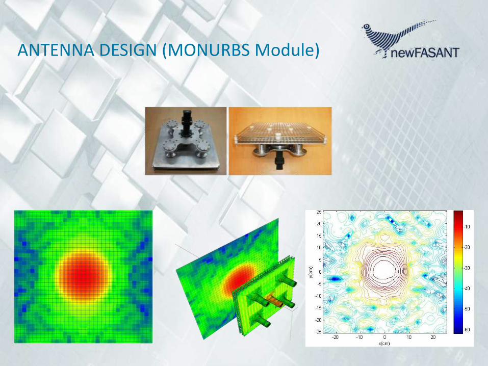
ANTENNA DESIGN (MONURBS Module) This module allows the efficient design of antennas and other structures
due to its parametric optimizer.
A large library of antenna primitives is available:
horns, patches, helices, Slot Vivaldi antennas, single and multiple reflectors, blades, coaxial feed antennas, spirals, arrays, etc.
The user can also build and optimize his own new antenna geometries.
ANTENNA DESIGN (MONURBS Module)
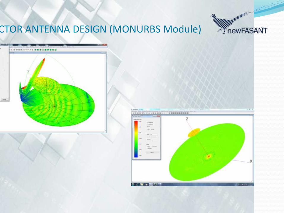
REFLECTOR ANTENNA DESIGN (MONURBS Module)

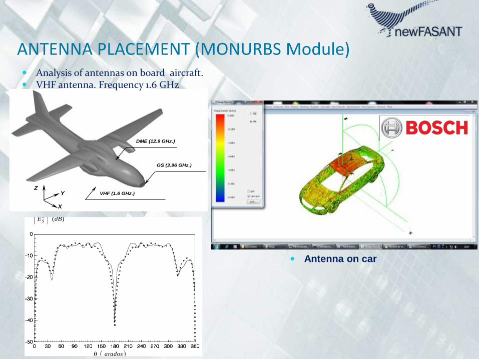
ANTENNA PLACEMENT (MONURBS Module)
VHF (1.6 GHz.)
X
YZ
GS (3.96 GHz.)
DME (12.9 GHz.)
Medidas PO MFIE-CGM#1
grados
)(dBES
grados
)(dBES
Analysis of antennas on board aircraft. VHF antenna. Frequency 1.6 GHz
Antenna on car


APPLICATION OF MONURBS TO A ESA EMC PROJECT
23
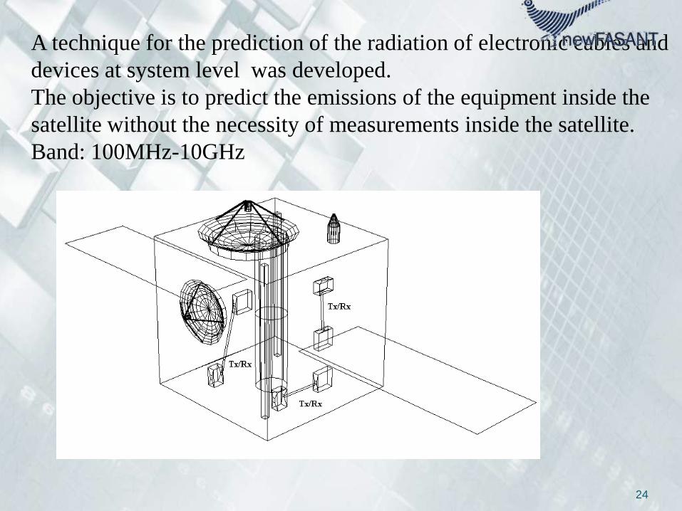
EFFECTIVE TECHNIQUE FOR SYSTEM LEVEL PREDICTION OF ELECTROMAGNETIC EMISSIONS FROM ELECTRONIC DEVICES
AND CABLES IN SATELLITES
ESA Project: “Effective alternative technique to radiated
system level verification”, TL-OF-075/2005. 2005-2006.
Results Published in IEEE Antennas & Propagation Magazine,
April 2010, pp 71 – 85
“A systematic approach for radiated system level verification of
unknown sources inside satellites from unit level measurements”.
F. Saez de Adana, M.F. Cátedra, J.M. Gómez, R. Mittra, J.
Berkowitsch, F. Gutiérrez, M. Alfonsea.
24
A technique for the prediction of the radiation of electronic cables and
devices at system level was developed.
The objective is to predict the emissions of the equipment inside the
satellite without the necessity of measurements inside the satellite.
Band: 100MHz-10GHz
25
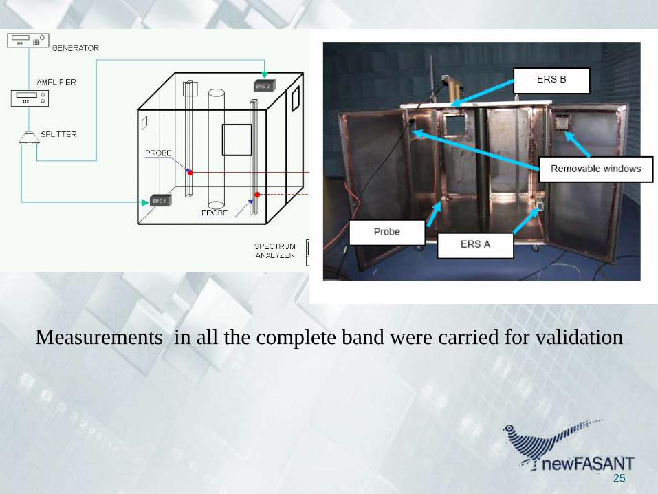
Measurements in all the complete band were carried for validation

26
Validation
Case 4: Two interconnected boxes.

27
Validation
• Frequency 4000 MHz
Probe rail 1 Probe rail 2
30
35
40
45
50
55
60
65
70
1 11 21 31 41 51 61 71 81 91 101
Et MoM Et OA
Et (dBV/m)
Point
30
35
40
45
50
55
60
65
70
1 11 21 31 41 51 61 71 81 91 101
Et MoM Et OA
Et (dBV/m)
Point

28
Validation
• Mean error and standard deviation
Frequency Mean error Standard
deviation
300 MHz 0.233 dB 0.231 dB
1500 MHz 1.128 dB 0.868 dB
4000 MHz 2.603 dB 2.799 dB
7000 MHz 2.088 dB 2.372 dB
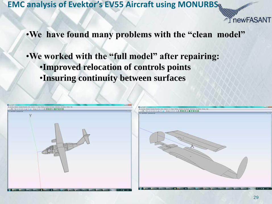
EMC analysis of Evektor’s EV55 Aircraft using MONURBS
29
•We have found many problems with the “clean model”
•We worked with the “full model” after repairing:
•Improved relocation of controls points
•Insuring continuity between surfaces
30
500 MHz
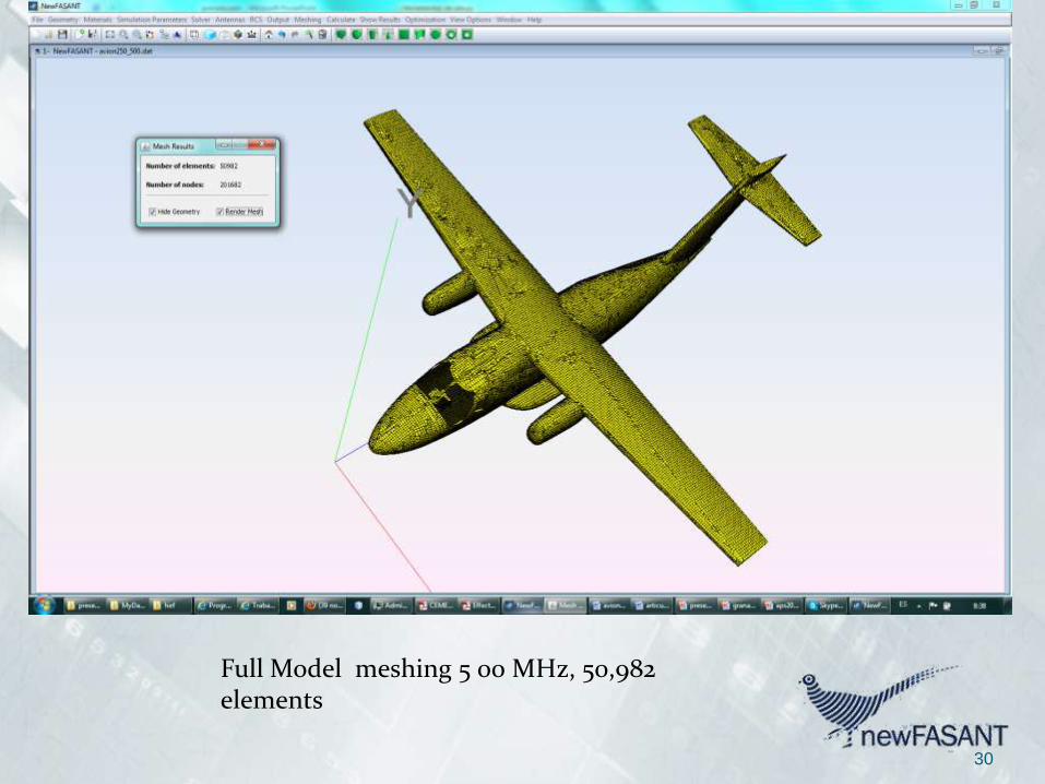
Full Model meshing 5 00 MHz, 50,982 elements

31
Current distribution, Full Model, 5 00 MHz, about 100,000 subdomains
MoM +MLFMM with preconditioner
32
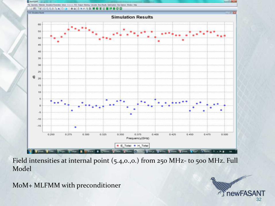
Field intensities at internal point (5.4,0.,0.) from 250 MHz- to 500 MHz. Full Model
MoM+ MLFMM with preconditioner
33
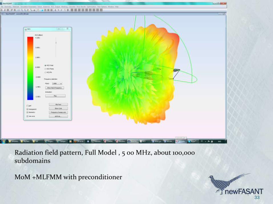
Radiation field pattern, Full Model , 5 00 MHz, about 100,000 subdomains
MoM +MLFMM with preconditioner


Impulse response (MONURBS Module)
Impulse response studies,
frequency 1.5 GHz

Impulse response (MONURBS Module)
Impulse response studies,
frequency 1.5 GHz

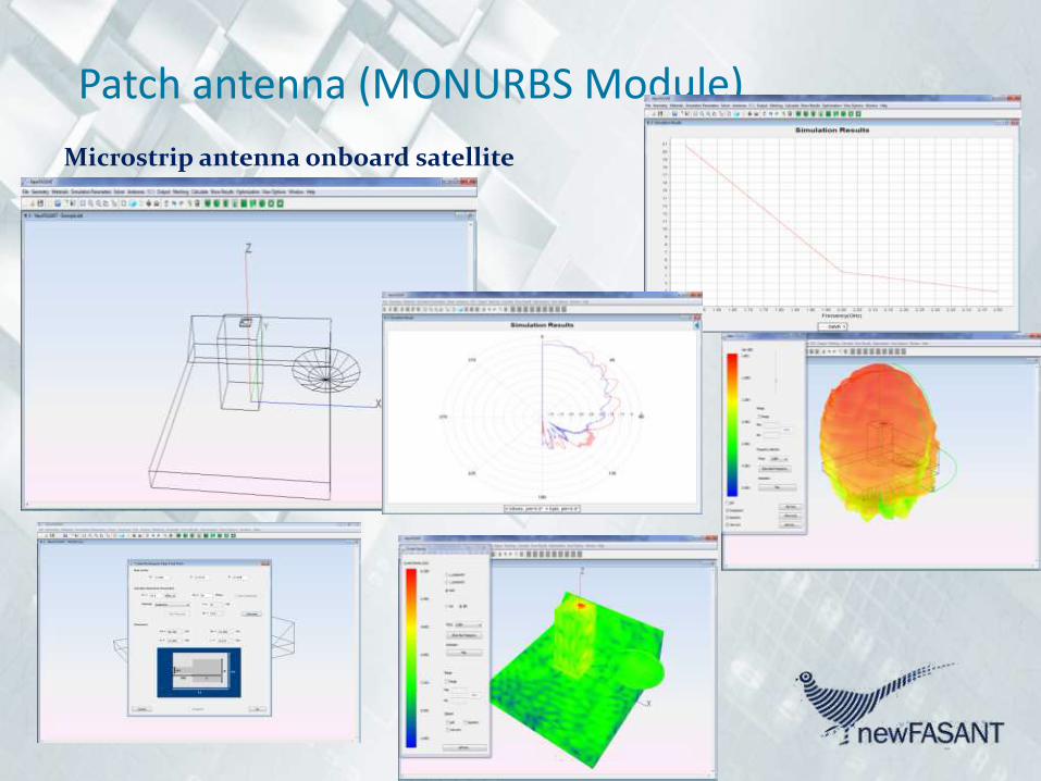
Patch antenna (MONURBS Module)
Microstrip antenna onboard satellite

Patch antenna (MONURBS Module)
Microstrip antenna on board rocket

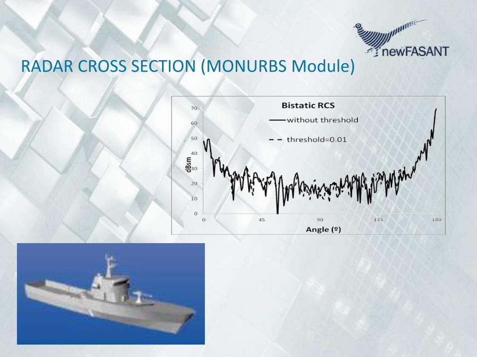
RADAR CROSS SECTION (MONURBS Module)
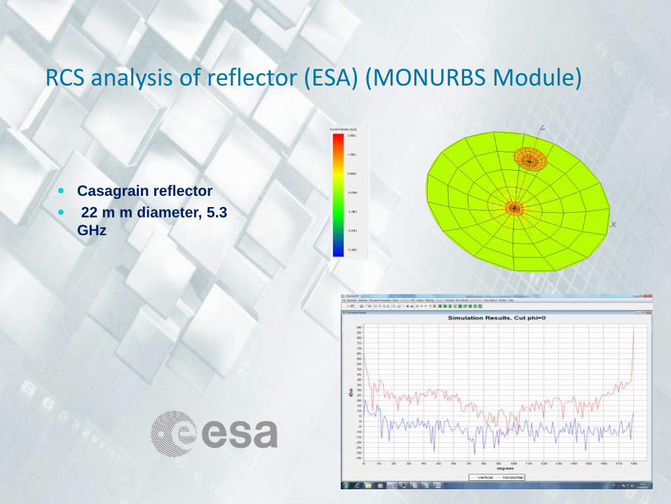
RCS analysis of reflector (ESA) (MONURBS Module)
Casagrain reflector
22 m m diameter, 5.3
GHz

RCS of cavities (MONURBS Module)
• The cavity is cylindrical,•with a depth of 4 m,•a radius of 1 m.•The fan is 0.8 m. from the cavity bottom.
• All the following results have been obtained for a freq. of 3GHz.•
•A laptop computer with a quad processor was used.
•The memory required in all the cases was lower than 6 GB,
•CPU-time for monostatic analysis, 15 min.
Cylinder with RAM in the left

FASANT - Module
FASANT is a very efficient computer tool for the 3D analysis of antennas onboard satellites, aircrafts and other complex bodies.
The kernel of the program is based on Geometrical Optics (GO), PhysicalOptics (PO) and Uniform Theory of Diffraction. A combination of the AngularZ-Buffer (AZB), the Volumetric Space Partitioning (SVP) and the A* heuristicalgorithm is applied for the ray-tracing acceleration.

Radio-Coverage Analysis (FASANT Module)

Radio-Coverage Analysis (FASANT Module)

Radio-Channel Analysis (FASANT Module)
FASANT also provides radio channel parameters:
impulse response, CDMA analysis, Power delay profiles, etc.

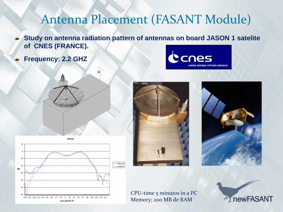
Antenna Placement (FASANT Module)
Study on antenna radiation pattern of antennas on board JASON 1 satelite
of CNES (FRANCE).
Frequency: 2.2 GHZ
Etheta
-60
-50
-40
-30
-20
-10
0
10
-180 -161 -142 -123 -104 -85 -66 -47 -28 -9 10 29 48 67 86 105 124 143 162
Cut phi=67.5º
dB
Measure
FASANT
CPU-time 5 minutos in a PCMemory; 200 MB de RAM


Radio-Channel Analysis (FASANT Module)
FASANT provides a new approachto analyze dynamic scenarios(some objects and/or antennas canhave translation and/or rotationmovements)

Radio-Channel Analysis (FASANT Module)
Static and dynamic results can be visualized:

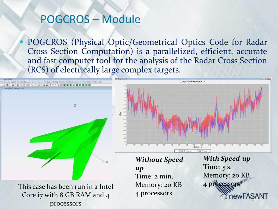
POGCROS – Module
POGCROS (Physical Optic/Geometrical Optics Code for RadarCross Section Computation) is a parallelized, efficient, accurateand fast computer tool for the analysis of the Radar Cross Section(RCS) of electrically large complex targets.
With Speed-upTime: 5 s.Memory: 20 KB4 processors
Without Speed-upTime: 2 min.Memory: 20 KB4 processors
This case has been run in a Intel Core i7 with 8 GB RAM and 4
processors

RCS of Cavities (POGCROS Module) The objects can include Perfect Electric Conductor (PEC), dieletric or magnetic
materials or PEC covered by Radar Absorbing Materials (RAM). POGCROS can alsohandle the interaction of terrestrial or maritime targets with their surroundingenvironment
POGCROS (PO)
MONURBS(MoM)
POGCROS takes less than 1 min formonostatic analysis (91 directions).
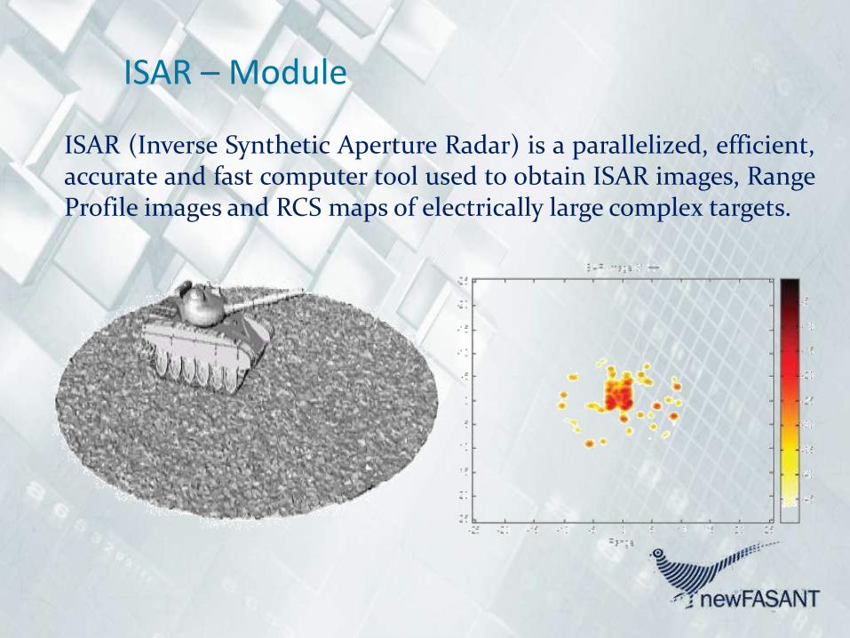
ISAR – Module
ISAR (Inverse Synthetic Aperture Radar) is a parallelized, efficient,accurate and fast computer tool used to obtain ISAR images, RangeProfile images and RCS maps of electrically large complex targets.

Range Profile (ISAR Module)

ISAR Computation (ISAR Module)
• For 3 GHz. Satellite mockup 64 x 64 samples. 1 GHz Bandwidth
• Angular margin 6º
=90º and =0º
Satellite Mockup
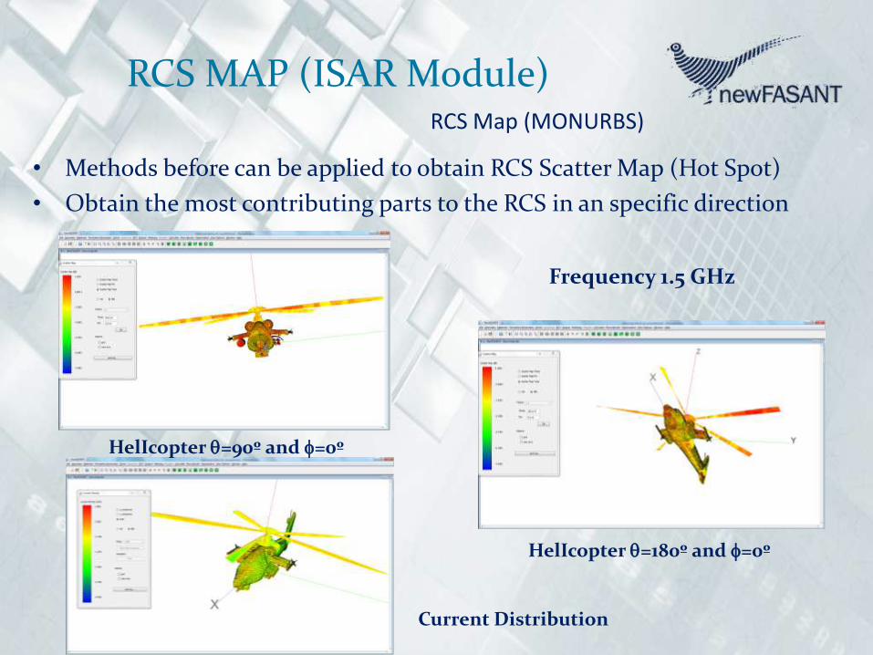
RCS MAP (ISAR Module)RCS Map (MONURBS)
• Methods before can be applied to obtain RCS Scatter Map (Hot Spot)
• Obtain the most contributing parts to the RCS in an specific direction
HelIcopter =90º and =0º
HelIcopter =180º and =0º
Frequency 1.5 GHz
Current Distribution
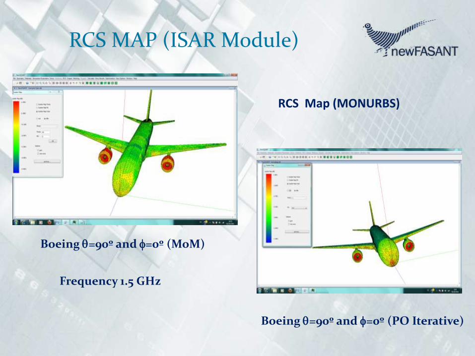
RCS MAP (ISAR Module)
RCS Map (MONURBS)
Boeing =90º and =0º (MoM)
Boeing =90º and =0º (PO Iterative)
Frequency 1.5 GHz


DOPPLER – Module
DOPPLER is a parallelized, efficient, accurate and fast computertool used to obtain Doppler frequency spectrum of electricallylarge complex bodies.

RCS of Moving Target (DOPPLER Module)
The cavity is cylindrical, with a depth of 4m, a radius of 1m. The fan is 0.8mfrom the cavity bottom. All the following results have been obtained with theprevious cavity with a two-blade fan for a frequency of 3 GHz.

RCS of Moving Target (DOPPLER Module)
Doppler Spectrum obtained using POGCROS, monostatic case, Theta= 10,phi=90. The blades are rotating with an angular speed of 1000 rad/s. About 3seconds of CPU.


IR – Module
INFRARED is an accurate and fast computer tool for the infraredanalysis of arbitrary structures, such as ground vehicles, aircrafts,ships… The parameters of the thermal scenario and exhaust gasescan be easily modeled with the graphical user interface provided.


RADOME – Module
RADOME moduleRADOME is a parallelized accurate and fast computertool for the analysis of antenna with radomes, including multilayerradomes with embedded Frequency Selective surfaces (FSS). An iterativeMoM approach is used in the simulations. Optimization features for theradome design are also included. radomo 2.8 metros phi=90
-3.00E+01
-2.00E+01
-1.00E+01
0.00E+00
1.00E+01
2.00E+01
3.00E+01
4.00E+01
1 11 21 31 41 51 61 71 81 91 101 111 121131 141 151 161 171 181
RADOME landa6
NO RADOME SIMPLE
Radome 4mm

72
Radomes/LensesDielectric radome with FSS at 15 GHz

73
Radomes/Lenses
Dielectric radome with FSS at 15 GHz

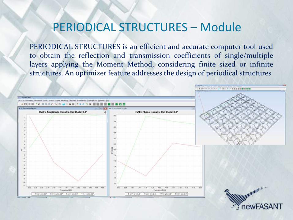
PERIODICAL STRUCTURES – Module
PERIODICAL STRUCTURES is an efficient and accurate computer tool usedto obtain the reflection and transmission coefficients of single/multiplelayers applying the Moment Method, considering finite sized or infinitestructures. An optimizer feature addresses the design of periodical structures

REFLECTARRAY – Module
5 6 7 8 9
x 10-3
-200
-150
-100
-50
0
50
100
150
200
250
Re
fle
cte
d P
ha
se
(d
eg
)
External Length (m)
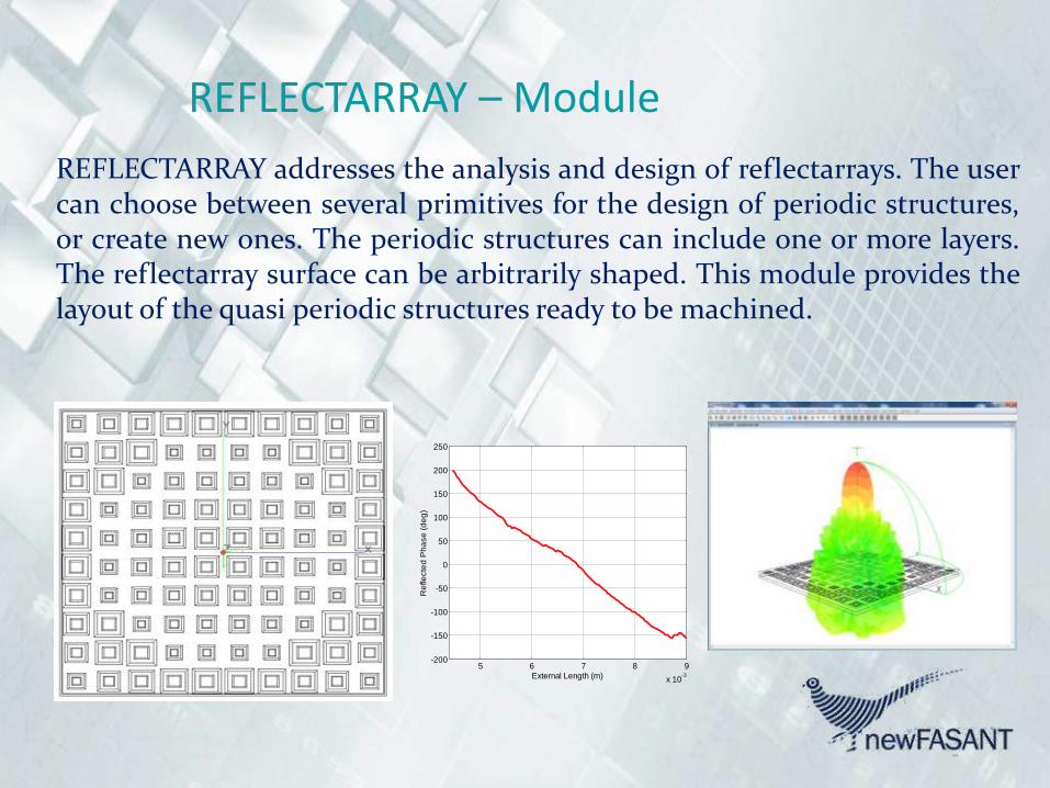
REFLECTARRAY addresses the analysis and design of reflectarrays. The usercan choose between several primitives for the design of periodic structures,or create new ones. The periodic structures can include one or more layers.The reflectarray surface can be arbitrarily shaped. This module provides thelayout of the quasi periodic structures ready to be machined.
REFLECTARRAY – Module
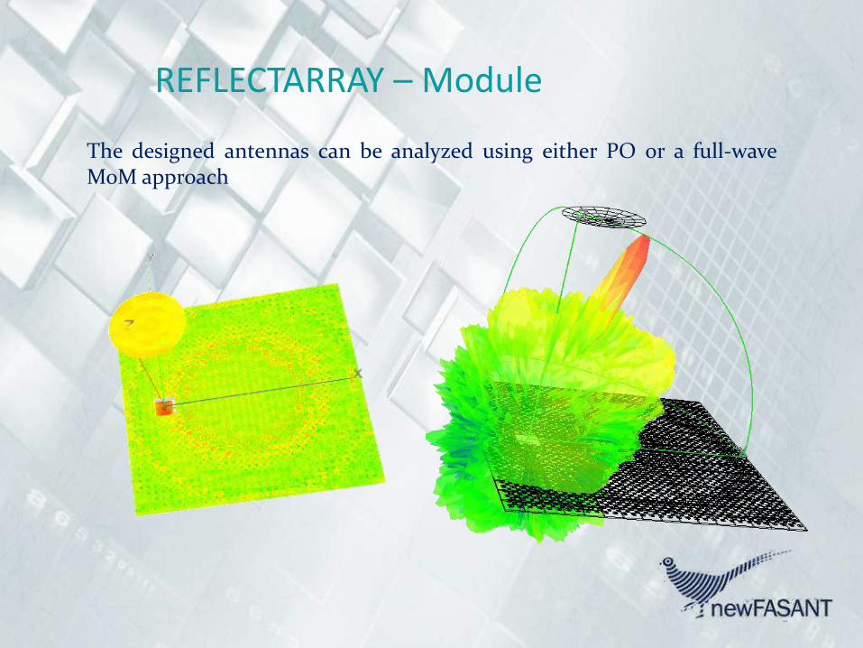
The designed antennas can be analyzed using either PO or a full-waveMoM approach

Three layers reflectoarray analysis (REFLECTARRAY Module)
Frequencies: 11.05 GHz and 12.1 GHz Polarization Dual

Dual Band Reflectoarray (REFLECTARRAY Module)
Frequencies: 12 and 14 GHz
81
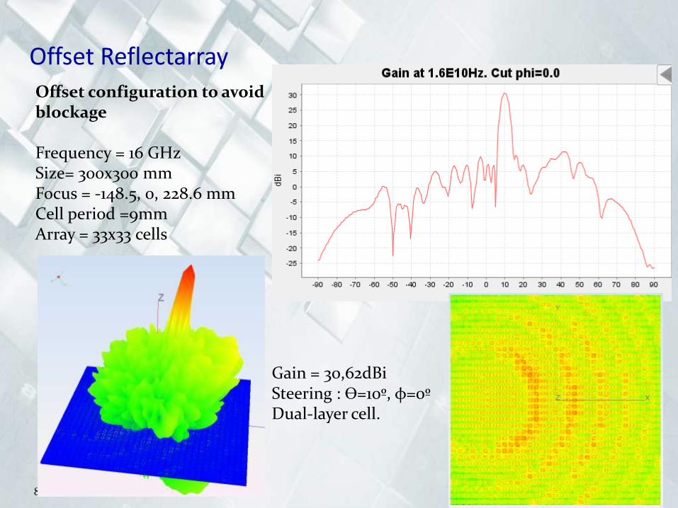
Offset configuration to avoidblockage
Frequency = 16 GHzSize= 300x300 mmFocus = -148.5, 0, 228.6 mmCell period =9mmArray = 33x33 cells
Gain = 30,62dBiSteering : ϴ=10º, φ=0ºDual-layer cell.
Offset Reflectarray
82
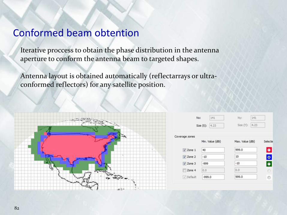
Iterative proccess to obtain the phase distribution in the antenna aperture to conform the antenna beam to targeted shapes.
Antenna layout is obtained automatically (reflectarrays or ultra-conformed reflectors) for any satellite position.
Conformed beam obtention

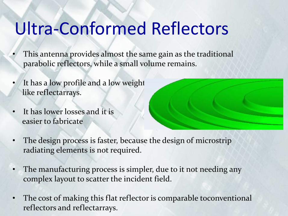
Ultra-Conformed Reflectors• This antenna provides almost the same gain as the traditional
parabolic reflectors, while a small volume remains.
• It has a low profile and a low weight like reflectarrays.
• It has lower losses and it is easier to fabricate
• The design process is faster, because the design of microstripradiating elements is not required.
• The manufacturing process is simpler, due to it not needing any complex layout to scatter the incident field.
• The cost of making this flat reflector is comparable toconventionalreflectors and reflectarrays.
85
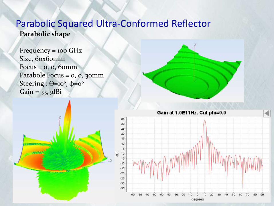
Parabolic shape
Frequency = 100 GHzSize, 60x60mmFocus = 0, 0, 60mmParabole Focus = 0, 0, 30mmSteering : ϴ=10º, φ=0ºGain = 33,3dBi
Parabolic Squared Ultra-Conformed Reflector

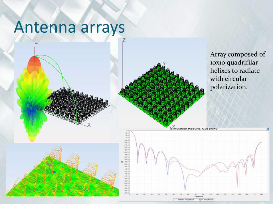
Antenna arrays
Array composed of 10x10 quadrifilar helixes to radiate with circular polarization.

Antenna arrays
Array composed of 20x20 conical horns fed to radiate with circular polarization.


CIRCUIT ANALYSIS – Module
Primitives for antennas and circuit components are available.Optimization tools are also available for the design of microstripcomponents, antennas and circuits
Hairpin Filter
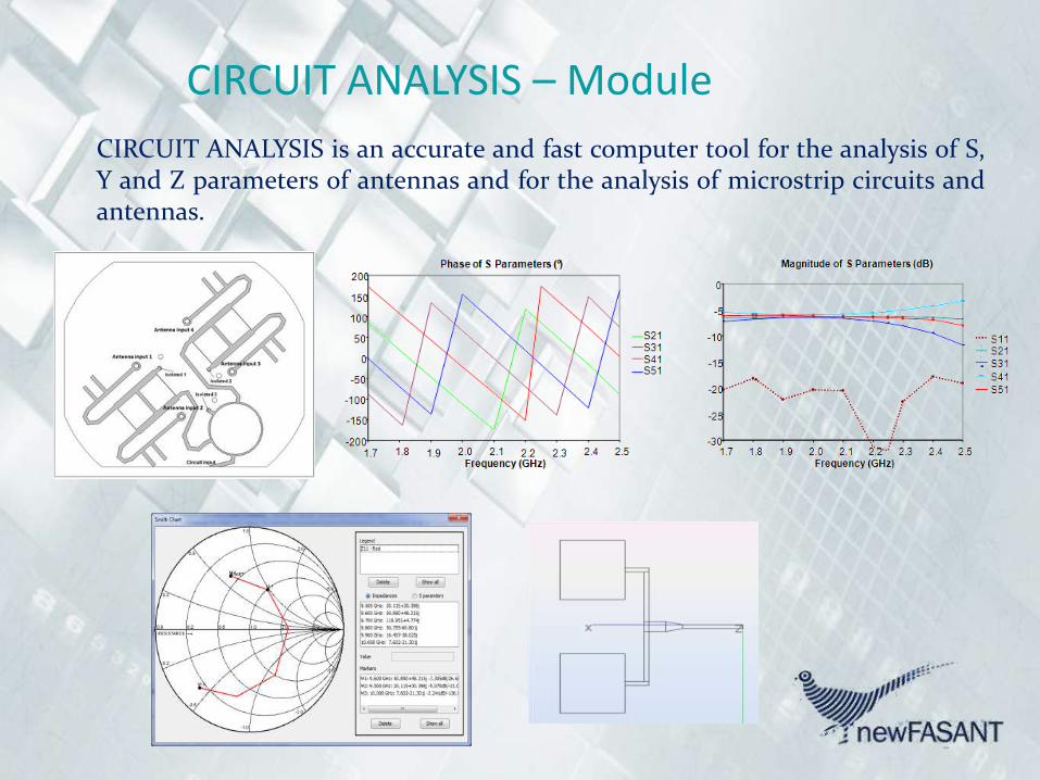
CIRCUIT ANALYSIS – Module
CIRCUIT ANALYSIS is an accurate and fast computer tool for the analysis of S,Y and Z parameters of antennas and for the analysis of microstrip circuits andantennas.


3. Testing Capabilities
Automatic Measurements in near field (planar, cylindrical andspherical)
anechoic chamber form 0.5 up to 40 GHz (6mx4mx3.8m) All software (mechanical control, scanning and field translation
developed by us)

5. Companies, institutes and universities involved in projects

5. Companies, institutes and universities involved in projects

CONTACT ADRESS:
NEWFASANT S.L.Avenida de Buendia 11,
19005 Guadalajara, Spain
Email: [email protected]


