88
Roller screws

Roller screws
SKF is a registered trademark of the SKF Group.
© SKF Group 2005-2008The contents of this publication are the copyright of the publisher and may not be reproduced (even extracts) unless prior written permission is granted.Every care has been taken to ensure the accuracy of the information contained in this publication but no liability can be accepted for any loss or damagewhether direct, indirect or consequential arising out of the use of the information contained herein.
Publication 4351 EN - 2008-01 Printed in France on environmentally friendly paper
ActuationBall & Roller screws
Represented by:

2
Servo_press
High tonnage press
Glue gun
Painting gun

General
3
3
4Other technical dataLead precision according to ISO ------------------------------------------------------------------------------------------- 24Preload adjustment ----------------------------------------------------------------------------------------------------------- 26Product inspection and certifi cation --------------------------------------------------------------------------------------- 27
5
GeneralOverview: roller screw nuts ------------------------------------------------------------------------------------------------- 04Comparing roller screws to ball screws ---------------------------------------------------------------------------------- 06The principle of planetary roller screws --------------------------------------------------------------------------------- 08The principle of recirculating roller screws ----------------------------------------------------------------------------- 09
2
1
Recommendations for selectionBasic and static load rating ------------------------------------------------------------------------------------------------- 10Critical rotating speed for screw shafts ---------------------------------------------------------------------------------- 11Permissible speed limit ------------------------------------------------------------------------------------------------------ 12Lubrication --------------------------------------------------------------------------------------------------------------------- 13Effi ciency and back-driving ------------------------------------------------------------------------------------------------- 14Axial play and preload -------------------------------------------------------------------------------------------------------- 15Static axial stiffness ----------------------------------------------------------------------------------------------------------- 19Screw shaft buckling --------------------------------------------------------------------------------------------------------- 19Materials and heat treatments --------------------------------------------------------------------------------------------- 20Shaft design -------------------------------------------------------------------------------------------------------------------- 21
Recommendations for assemblyRadial and moment loads --------------------------------------------------------------------------------------------------- 23Alignment ----------------------------------------------------------------------------------------------------------------------- 23Lubrication ---------------------------------------------------------------------------------------------------------------------- 23Designing the screw shaft ends ------------------------------------------------------------------------------------------- 23Starting-up the screw ------------------------------------------------------------------------------------------------------- 23Operating temperature ------------------------------------------------------------------------------------------------------ 23
Rollingelement
Load CoØ
d
Product informationService Range Capabilities ---------------------------------------------------------------------------------------------------------------------- 28Range details ------------------------------------------------------------------------------------------------------------------- 30Flanged thrust bearings, FLRBU ------------------------------------------------------------------------------------------ 33
Standard Range Planetary roller screws: technical data and dimensions ------------------------------------------------------------- 36Recirculating roller screws: technical data and dimensions --------------------------------------------------------- 62Flanged thrust bearings, FLRBU ------------------------------------------------------------------------------------------ 72
Ultra Power Range Technical data and dimension ---------------------------------------------------------------------------------------------- 76
Electro-mechanical cylinders --------------------------------------------------------------------------------------------- 80SKF worldwide ---------------------------------------------------------------------------------------------------------------- 83Calculation formulas -------------------------------------------------------------------------------------------------------- 84Symbols ------------------------------------------------------------------------------------------------------------------------- 86Ordering code ----------------------------------------------------------------------------------------------------------------- 87

General
4
Overview:nuts for roller screws
Planetary roller screws
Recirculating roller screws

General
5
1
TRU/PRU Cylindrical backlash elimination: TRUPreloaded: PRU
SRC, Cylindrical axial playBRC, backlash elimination
TRK/PRKFlanged backlash elimination: TRKPreloaded: PRK
SRF, Flanged axial play BRF, backlash elimination
PVUCylindrical preloaded
SVC, Cylindrical axial playBVC, backlash elimination
PVKFlange preloaded
SVF, Flanged axial playBVF, backlash elimination

General
6
The load carrying capacity of a rolling screw depends practically on the surfaces at the points of contact:
n their diametern the number of contactsn their hardnessn their surface fi nish
n the precision of the contacts to assure load sharing between them.
Comparing roller screws to ball screws
Roller screws
In roller screws, the load is transmitted from the nut to the shaft through the barrelled surfaces of all the engaged rollers. The diameter of the contact surface is substantially increased as is the number of points of contact.
2 types of roller screws
Planetary roller screwThreaded rollers are the basis of “SR / BR / TR / PR” planetary roller screws.
Recirculating roller screwGrooved rollers are the basis of “SV /BV / PV” recirculating roller screws.
Contact surfaces
DiameterNumberHardnessSurface finishPrecision
Load rating
E
E
===
E E
=====
=
Ball screws
In ball screws, the load is transmitted from the nut to the shaft through the balls engaged in the groove.
In a single start ball screw, the ball diameter is limited to approximately 70 % of the lead: there is only a single helix of balls in a nut of given length so the number of contacts is small.
Extended life
Minimum maintenance costs
More reliableoperation

General
n High load ratings (SR-SV)n Very high rotational speed
(SR)n High acceleration and
deceleration rates (SR)n Long life at high cycling rates
(SR)n High reliability (SR-SV)n Resistance to hostile surroundings (SR)
n Ability to survive shock loads (SR)
n Small displacements with very good repeatability (SV)
n Rotating the nut when speed becomes critical (SR)
n Frequently removing the nut from the screw shaft
(SR-most SV).
7
1
Higher acceleration over12 000 rad/sec2
Stainless steels
Higher static load up to 1000 tonnes
Higher dynamic load up to 200 tonnes
Higher rotational speed Ø 48 at over 3000 rpm
Shock loads
Adverseenvironmentsdust, ice, sand
1 mm LeadSR SV SR
SVSV
SR
SR SR
SR
SR SV
Break out from the limitations of ball screw performance
The 10 reasonsfor using roller screws
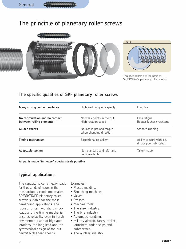
Many strong contact surfaces High load carrying capacity Long life
No recirculation and no contact No weak points in the nut Less fatiguebetween rolling elements High rotation speed Robust & shock resistant
Guided rollers No loss in preload torque Smooth running when changing direction
Timing mechanism Exceptional reliability Ability to work with ice, dirt or poor lubrication
Adaptable tooling Non standard and left hand Tailor-made leads available
All parts made “in house”, special steels possible
General
8
The capacity to carry heavy loads for thousands of hours in the most arduous conditions makes SR/BR/TR/PR planetary roller screws suitable for the most demanding applications. The robust nut can withstand shock loads and the timing mechanism ensures reliability even in harsh environments and at high acce-lerations; the long lead and the symmetrical design of the nut permit high linear speeds.
Examples:• Plastic molding.• Broaching machines.• Valves.• Presses• Machine tools.• The steel industry.• The tyre industry.• Automatic handling.• Military aircraft, tanks, rocket
launchers, radar, ships and submarines.
• The nuclear industry.
The principle of planetary roller screws
Threaded rollers are the basis of SR/BR/TR/PR planetary roller screws.
fi g. 1
The specific qualities of SKF planetary roller screws
Typical applications

General
9
1
Ultimate positioning accuracy can be obtained using the fi ne lead of SV/BV/PV recirculating roller screws. Their great mechanical advantage minimizes input tor-que and increases resolution. They can simplify a complete transmission and improve its rigidity. They are often used in applications of advancing tech-nology where reliable optimum performance is vital.
Examples:• Grinding machines• Laboratory equipment.• Hospital equipment.• Paper making• The printing industry• Telescopes• Satellites
The principle of recirculating roller screws
Grooved rollers are the basis of SV/BV/PV recirculating roller screws.
fi g. 1
The specific qualities of SKF recirculating roller screws
Very small leads (1mm) Fine resolution Minimum drive torque High mechanical advantage
No miniature parts Simple Robust Reliable
Many strong contact Heavy load High rigidity Long lifepoints carrying capacity
All parts made “in house”, special steels possible
Typical applications

Recommendations for selection
10
Basic dynamic load rating (Ca)
The dynamic rating is used to compute the fatigue life of roller screws. It is the axial load cons-tant in magnitude and direction, and acting centrally under which the nominal life (as defi ned by ISO) reaches one million revolu-tions.
Nominal fatigue life L10The nominal life of a roller screw is the number of revolutions (or the number of operating hours at a given constant speed) which the roller screw is capable of enduring before the fi rst sign of fatigue (fl aking, spalling) occurs on one of the rolling surfaces (screw, nut or roller thread or groove).
It is however evident from both laboratory tests and practi-cal experience that seemingly identical roller screws operating under identical conditions have different lives, hence the notion of nominal life. It is, in accordance with ISO defi nition, the life achieved or exceeded by 90 % of a suffi ciently large group of apparently identi-cal roller screws, working in iden-tical conditions (alignment, axial and centrally applied load, speed, acceleration, lubrication, tempe-rature and cleanliness).
Service lifeIt is the actual life achieved by a specifi c roller screw before it fails. Failure is not only by fatigue (fl aking or spalling); but also by inadequate lubrication and wear; wear of the recirculation system, corrosion, contamination, and, more generally, by loss of the functional characteristics required by the application. Experience acquired with similar applications will help to select the proper screw to obtain the required service life. Also, one must take into account structural requirements such as the strength of screw ends and nut attach-ments, due to the loads applied on the elements in service. To attain L10 life performance a mean working load of up to 80 % of Ca is permitted.
Recommendations for selection
Only basic selection parameters are included. To make the very best selection of a roller screw, the designer should specify such critical parameters as the load spectrum, the linear or rotational speed, the rates of acceleration and deceleration, the cycle rate, the environment, the required life, the lead accuracy, the stiffness, and any special requirement. If in doubt, please consult an SKF specialist before placing an order.
(1) SKF can help you to define this value in relation with the actual conditions of service.
In cases where more than 90 % probability of a screw attaining or exceeding its life is required.
% reliability Adjusted life
90 % 1,00 ™ L10 95 % 0,62 ™ L10 96 % 0,53 ™ L10 97 % 0,44 ™ L10 98 % 0,33 ™ L10 99 % 0,21 ™ L10
Life test bench

Recommendations for selection
11
1
Equivalent dynamic loadsThe loads acting on the screw can be calculated according to the laws of mechanics if the external forces (e.g. power transmission, work, rotary and linear inertia forces) are known or can be cal-culated. It is necessary to calcula-te the equivalent dynamic load (see page 84). Radial and moment loads must be taken by linear guiding systems. It is extremely important to resolve these problems at the earliest conceptual stage. These forces are detrimental to the life and the expected performance of the screw.
Fluctuating loadWhen the load fl uctuates during the working cycle, it is necessary to calculate the equivalent dyna-mic load: this load is defi ned as that hypothetical load, constant in magnitude and direction, acting axially and centrally on the screw which, if applied, would have the same infl uence on the screw life as the actual loads to which the screw is subjected. Additional loads due, for example to misalignment, uneven loading, shocks, and so on, must be taken in account. Their infl uence on the nominal life of the screw is generally taken care of, consult SKF for advice.
Static load carrying capacity (Coa)
Roller screws should be selected on the basis of the static load rating Coa instead of on life when they are submitted to continuous or intermittent shock loads, while stationary or rotating at very low speed for short duration. The permissible load is deter-mined by the permanent defor-mation caused by the load acting at the contact points. It is defi ned by ISO standards as the purely axially and centrally applied static load which will create, by calculation, a total (rol-ling element + thread surface) permanent deformation equal to 0.0001 of the diameter of curva-ture of the rolling element. This deformation corresponds to a contact Hertz stress up to 4500 MPa depending on the screw dia-meter. The roller screw must be selected by its basic static load rating which must be, at least, equal to the product of the maxi-mum axial static load applied and a safety factor “so”. The safety factor is selected in relation with past experience of similar applications and require-ments of running smoothness and noise level (1).
Critical rotating speed for screw shafts
The shaft is equated to a cylinder the diameter of which is the root diameter of the thread. The for-mulas (see page 84) use a para-meter the value of which is dictated by the mounting of the screw shaft (whether it is simply supported or fi xed). As a rule the nut is not consi-dered as a support of the screw shaft. Because of the potential inaccuracies in the mounting of the screw assembly, a safety fac-tor of 0.80 is applied to the cal-culated critical speeds. Calculations which consider the nut as a support of the shaft, or reduce the safety factor, requi-re practical tests and possibly an optimization of the design (1).
(1) SKF can help you to define this value in relation with the actual conditions of service.
2

Recommendations for selection
12
Permissible speed limit
The permissible speed limit is that speed which a screw cannot reliably exceed at any time. It is generally the limiting speed of the centrifugal forces in the nut. It is expressed as the product of the rpm and the diameter of the screw shaft (in mm). The speed limits quoted in this catalogue (see page 84) are the maximum speed that may be applied through very short periods and in optimized running condi-tions of alignment, light external load and preload with monitored lubrication. Running a screw continuously at the permissible speed limit may lead to a reduction of the calculated life of the nut mecha-nism.
High speed associated with high load requires a large input torque and yields a relatively short nominal life (1). In the case of high accelera-tion and deceleration, it is recom-mended to either work under a nominal external load or to apply a light preload to the nut to avoid internal sliding during reversal. The value of the preload of screws submitted to high accele-ration is that preload which ensures the rolling elements do not slide (1). Too high a preload will create unacceptable increases of the internal temperature.
Lubrication
The key point is the initial lubri-cation of the nut to lubricate all components. The lubrication of screws rotating at high speed must be properly considered in quantity and quality.
The volume, spread and fre-quency of the application of the lubricant (oil or grease) must be properly selected and monitored.At high speed the lubricant spread on the surface of the screw shaft may be thrown off by centrifugal forces. It is important to monitor this phenomenon during the fi rst run at high speed and possibly adapt the frequency of re-lubrication or the fl ow of lubricant, or select a lubricant with a higher viscosity. Monitoring the steady tempe-rature reached by the nut permits the frequency of re-lubrication or the oil fl ow rate to be optimized.
Oil lubrication
A centralised recirculating oil system is ideal because it continuously changes the oil in the nut with cooled fi ltered oil from the reservoir. This system is prescribed when the temperature is likely to affect the positioning accuracy. The fl ow of oil can be regulated to optimise fi lm thic-kness and removal of heat.
Selection of oilMineral oil normally used to lubricate other rotating parts such as bearings and gears may be used for the screw. The viscosity of the oil is defi ned by the speed, running temperature and load. The oil should have a viscosity of 100 ISO at the running temperature. An increase in viscosity or speed will increase the running temperature. At low speed (< 10 rpm) the viscosity should be 200 ISO at the run-ning temperature. Under heavy load an EP additive to improve the fi lm strength is recommen-ded. Corrosion resistant and stabilizing additives may also be used to advantage. Synthetic oils (PAO, ester) are advised for long life, high tempe-rature. Barium soap is advised under heavy load, low speed and when adhesion is required.
(1) SKF can help you to define this value in relation with the actual conditions of service.
!

Recommendations for selection
13
Grease lubrication
Where oil lubrication is not prac-ticable, the grease recommended for the support bearings of the screw may also be used for the screw. After a few full strokes the grease will be spread evenly over the useful threaded length of the screw shaft, which will also help to protect the screw against corrosion. However the grease is open to the air. To prevent dirt which may fall on it from entering the nut, wipers should be mounted in each end of the nut. Also the grease on the screw shaft will age more quickly than that in the screw support bearings so more frequent regreasing is needed, especially in a dirty environment. If the screw cannot be dis-mounted and cleaned before regreasing it is necessary to thoroughly clean the old grease from the screw shaft. This can be done with a spatula and then with a clean fl uff proof cloth. To clean even more a cloth wet-ted with a solvent such as white spirit may be used. We do not advise using brushes to remove old or spread new grease (risk of bristles coming out). Apply also the new grease through the nut to push out the old from inside the nut. The grease type is defi ned above all by the operating tem-perature, environment and load on the screw. Speed, starting torque and chemical compatibility may also be taken into consideration. Normally bearing greases of NLGI consistency 2 are used. A grease which is too hard at low temperature may restrict rotation or one which is too soft at high temperature may run off.
Selection of greaseLithium base greases, for stan-dard applications with EP-additi-ves, are generally suitable for use from –30 °C to +110 °C. A few can be used to +150 °CLithium base greases are virtually insoluble in water and very work stable. However they absorb large quantities of water when worked to extremes.
Lubrication intervalThe lubrication interval depends on the working cycle of the screw and whether the lubricant is pol-luted during use. General advice is diffi cult but the following will help you to defi ne the interval. On start up check the grease quality regularly, for instance every month. The fi rst re-lubrication has to be done after roughly 50 000 revolutions under load, to remove all particles generated during running-in. If the viscosity of the grease sample has increased, it needs replacing. If the grease sample is darker than new it may indicate oxida-tion or the presence of metallic particles. If it is discoloured, it is proba-bly mixed with water. It is helpful to take samples not only from the part of the screw where running has occu-red but also from unused parts of the screw where the grease acts as corrosion preventer.
(1) SKF can help you to define this value in relation with the actual conditions of service.
2

Recommendations for selection
14
Quantity of lubricant
• OilWe advise a quantity of 5 › 25 cm3/h in shots of 0,1 cm3 as an order of magnitude depen-ding on the size of the screw and its running conditions.
• GreaseThe total volume of grease nee-ded for a new roller screw is the sum of the quantities needed for the screw shaft and the nut. The volume of grease neces-sary for the screw shaft Zs can be estimated from this formula:
This quantity of grease should be spread over the whole threaded length of the shaft. The volume of grease for the nut Zn is one third of the free volume in the nut. The quantity Zn is given in the dimension tables: it should be injected through the lubrication hole while turning the shaft. Before applying load the nut should be run twice along the complete stroke to ensure grease is evenly spread.
Relubrication, see also ‘Grease lubrication’In the case of the existing grease being polluted, remove as much of it as possible and apply the same quantity as when fi rst lubricated. If the existing grease is clean add a volume Zn /3 into the nut. Generally speaking, it is better to inject small quantity frequently than the contrary.
Efficiency and back-driving
The performance of a screw is mainly dependant on the geo-metry of the contact surfaces and their fi nish as well as the helix angle of the thread. It is, also, dependant on the working conditions of the screw (load, speed, lubrication, preload, alignment, etc…). The “direct effi ciency” is used to defi ne the input torque requi-red to transform the rotation of one member into the translation of the other. Conversely, the “indirect effi ciency” is used to defi ne the axial load required to transform the translation of one member into the rotation of the other one. It is used, also, to defi -ne the braking torque required to prevent that rotation. These screws are reversible or back-driveable under almost all circumstances. It is therefore necessary to design a brake mechanism if backdriving is to be avoided (gear reducers or brake).
Preload torque: Internally preloaded screws exhi-bit a torque due to this preload. This persists even when they are not externally loaded. Preload torque is measured at 50 rpm when assembly is lubricated with ISO grade 64 oil.
Starting torque: This is defi ned as the torque nee-ded to overcome the following to start rotation:a) the total inertia of all moving parts accelerated by the energy source (including rotation and linear movement).b) the internal friction of the screw/nut assembly, bearing and associated guiding devices. In general, torque to overcome inertia (a) is greater than friction torque (b). The coeffi cient of friction of the high effi ciency screw when starting µs is estimated at up to double the dynamic coeffi cient µ, under normal conditions of use.
(1) SKF can help you to define this value in relation with the actual conditions of service.
Friction Back drivingtorque Tf
> torque Tr
Zs = 4,4 ™ 10-4 d0l1

Recommendations for selection
15
Axial play and preload
Preloaded nuts are subject to much less elastic deformation than non-preloaded nuts. Therefore they should be used whenever the accuracy of positio-ning under load and stiffness are important.
Preload, preload torque and rigidity
When a roller screw with a whole nut with axial play is measured on a tensile testing machine, a graph similar to (fi g. 1) is obtai-ned. One objective of preloading is to eliminate the axial play so that positioning accuracy is improved when the external load changes direction. Planetary roller screws are available with play elimination using whole nut (designation: BR) or split nut (designation: TR). In this case the preload torque will be between 0 and Tpe measu-red at 50 rpm when lubricated with ISO grade 68 oil. Planetary and recirculating roller screws are also available preloaded for optimum rigidity: their designations are PR and PV. (fi g. 2) shows how a squeeze load Fq is applied to the nut halves 1 and 2 of a split nut to obtain a preload Fpr . One part of this load is used to generate the preload force and the other one to squeeze the spacer. The preload spacer is ground to give the correct preload torque when the specifi ed squeeze load is applied. Before the external load is applied the two nut halves are in equilibrium at A (fi g. 4) under a load Fpr .
When an external load F (fi g. 3) is applied the loads on the nut hal-ves become F1 and F2. For all conditions where F ≤ 2,83 Fpr the load seen by nut half 2 is greater than the external load so increasing the preload reduces the life of the screw. When the external load reaches 2,83 Fpr nut half 1 is unloaded and F2 = F. Roller screws are normally preloaded by preloading one nut half against the other so only one half supports the exter-nal load in a given direction. In this case, nut half 2 is taking the external load. The load carrying capacity and rigidity of a split preloaded nut are substantially less than a whole nut. Because of the very high load capacity and rigidity of roller screws a split nut is suffi cient for most applications and offers an extremely compact design.
+
+
-
-
5000
- 10 10 20 30- 20- 30
- 5000
- 10000
- 15000
10000
15000LoadN
Play
Deflectionµm
fi g. 1
FqFq
FprFpr
fi g. 2
Fq
F
Fq
F2F1
1 2
+
+
2
1
F2
F1
FA
d
Fpr
2,83 Fpr
0
0 10 20 30
2000
5000
10000LoadN
Deflectionµm
fi g. 4
fi g. 3
2

Recommendations for selection
16
Figure 5 compares the load/defl ection characteristics of three different nut combinations:Curve 1. Whole nut with axial
playCurve 2. Preloaded split nutCurve 3. Preloaded double nut. Backlash elimination can be achieved by fi tting oversize rollers in one-piece nut (BRC-BVC) which allows to keep high load capacities. In exceptional cases where the load rating of a split nut is not suffi cient two whole cylindrical nuts may be preloaded together (fi g. 6). Exact dimensions are available on request: please con-tact SKF.
The squeeze load applies a compressive preload in all cases: this ensures more rigidity of the roller screw compared to a pre-load in extension. Preload torque is the torque resulting from the preload, Fpr. The preload torque is calculated from the nominal preload assu-ming a real effi ciency of 90 % of the theoretical direct effi ciency (page 85).
The preload torque,
+
+
-
-
5000
- 10
10 20 30
- 20- 30
- 5000
- 10000
- 15000
10000
15000
LoadN 3 1
2
Deflectionµm
fi g. 6fi g. 5
Tpr = Fpr Ph 10-3
( 1
- 1 )
π hp

Recommendations for selection
17
2
Preload torque tolerancesFor each roller screw, preloaded for optimum rigidity a range of value of preload torque , Tpr is given in the technical data. The customer is free to choose any value in this range: if no value is specifi ed on the order the mean value will be taken. A typical pre-load torque graph is shown on page 18: they can be obtained on request when ordering. The reference Rnr value of rigidity correspond to this mean preload torque value. The tolerance of variation of preload torque as the nut moves along the length of the screw depends on the helix angle of the screw thread, the slenderness of the screw shaft and the lead pre-cision. The tables give the tole-rances of preload torque variation. Refer to A if the helix angle, a is less than 11° and B if it is more. Preload torque is measured at 50 rpm with ISO grade 68 oil for SR/TR/PR screws and with ISO grade 220 oil for SV/PV screws.
A. Tolerance of preload torque for screws with a < 11°
l1/d0 ≤ 40 and l1 ≤ 4000 l1/d0 ≤ 60 and l1 ≤ 4000
Tpr G1 G3 G5 G1 G3 G5 Nm ±%
≤0,2 35 40 50 40 50 60 (0,2) - 0,6 25 30 35 30 35 40 (0,6) - 1,0 20 25 30 25 30 35 (1,0) - 2,5 15 20 25 20 25 30 (2,5) - 6,3 10 15 20 15 20 25 (6,3) - 10,0 10 10 15 15 15 20
B. Tolerance of preload torque for screws with a ≥ 11°
l1 ≤ 2000 2000 ≤ l1 ≤ 4000
Tpr G3 G5 G3 G5 Nm ±%
0 - 10,0 70 80 80 90
Planetary roller screws preloaded for optimum rigidity with a ≥ 11° are not available in G1 lead precision.
Recommendations for selection
18
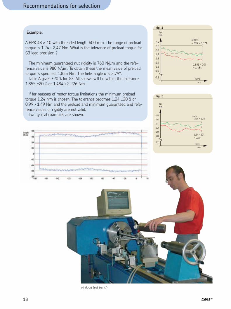
Example:
A PRK 48 ™ 10 with threaded length 600 mm. The range of preload torque is 1,24 › 2,47 Nm. What is the tolerance of preload torque for G3 lead precision ?
The minimum guaranteed nut rigidity is 760 N/µm and the refe-rence value is 980 N/µm. To obtain these the mean value of preload torque is specified: 1,855 Nm. The helix angle a is 3,79°. Table A gives ±20 % for G3. All screws will be within the tolerance 1,855 ±20 % or 1,484 › 2,226 Nm.
If for reasons of motor torque limitations the minimum preload torque 1,24 Nm is chosen. The tolerance becomes 1,24 ±20 % or 0,99 › 1,49 Nm and the preload and minimum guaranteed and refe-rence values of rigidity are not valid. Two typical examples are shown. 1,8
1,6
1,4
1,2
1,0
0,8
Travelmm
+ 20% = 1,491,24
= 0,991,24 - 20%
TprNm
0,2
fi g. 2
2,42,22,01,81,61,41,21,0
Travelmm
+ 20% = 0,3711,855
= 1,4841,855 - 20%
TprNm
0,2
fi g. 1
Preload test bench

Recommendations for selection
19
2
Static axial stiffness of a complete assembly
It is the ratio of the external axial load applied on the system and the axial displacement of the face of the nut in relation with the fi xed (anchored) end of the screw shaft. The inverse of the rigidity of the total system is equal to the sum of all the inverses of the rigidity of each of the compo-nents (screw shaft, nut as moun-ted on the shaft, supporting bearing, supporting housings, etc…).
Because of this, the rigidity of the total system is always less than the smallest individual rigi-dity.
Nut rigidity: RnWhen a preload is applied to a split nut, fi rstly, the internal play is eliminated, then, the Hertzian elastic deformation increases as the preload applied so that the overall rigidity increases. The theoretical deformation does not take into account machining inaccuracies, actual sharing of the load between the different contact surfaces, the elasticity of the nut and of the screw shaft. The practical stiffness values given in the cata-logue are lower than the theore-tical values for this reason. They are determined by SKF based on the value of the selec-ted basic preload and an external load equal to twice this preload.
Shaft rigidity: RsThe elastic deformation of screw shaft is proportional to its length and inversely proportional to the square of the root diameter. According to the relative importance of the screw defor-mation (see rigidity of the total system), too large an increase in the preload of the nut and sup-porting bearings yields a limited increase of rigidity and notably increases the preload torque and therefore the running tem-perature. Consequently, the preload sta-ted in the catalogue for each dimension is optimum and should not be increased.
for standard steelsee fi g. 1
for standard steel see fi g. 2
Screw shaft buckling
The column loading of the screw shaft must be checked when it is submitted to compression loading (whether dynamically or statical-ly). The maximum permissible compressive load is calculated using the Euler formulas. It is then multiplied by a safety factor of 3 to 5, depending on the application. The type of end mounting of the shaft is critical to select the proper coeffi cients to be used in the Euler formulas. When the screw shaft compri-ses a single diameter, the root diameter is used for the calcula-tion. When the screw comprises different sections with various diameters, calculations become more complex (1).
l
l2
fi g. 2
F
Fl
d
fi g. 1
(1) SKF can help you to define this value in relation with the actual conditions of service.
1 =
1 + 1
Rt Rs Rn
d2
2
Rs = 165 ––– (N/µm) l
165 d22 l
Rs = –––––––––––––– l2 (l - l2)

Recommendations for selection
Materials and heat treatments
Standard screw shafts are machined from pretreated 42 CrMo4.
Standard nuts are machined in 100Cr6 steel which is through hardened. Hardness of the con-tact surfaces is 56-60 HRc. Most assemblies made of stainless material have a surface hardness in the range 42 to 58 HRc: the load rating of the cata-logue therefore must be derated respectively to C’a and C’oaC’a and C’oa being the capacities with the new hardness in Vickers (Hv).
Working environment
Our products have not been developed for use in an explosive atmosphere, consequently we cannot take any responsibility for their use in this fi eld.
NOTE: 42 CrMo4, an AFNOR reference is similar to AISI 4140; 100Cr6 is similar to AISI 52100.
Shaft Design
It is possible to deliver roller screws with one end larger than the outside diameter, d1 of the shaft. To grind the thread effi -ciently an undercut at root dia-meter d2 and length l2 is needed (fi g. 1).
• When d3 ≤ 1,3 d1
SR/BR/TR/PRPh ≤ 8 mm, l2 ≥ 12 mmPh > 8 mm, l2 ≥ 1,4 Ph
SV/BV/PVPh = 1+ 40 ™ 2, 50 ™ 2, l2 ≥ 12 mm63 ™ 2 All others l2 ≥ 14 mm
• When d3 ≥ 1,3 d1, contact SKF
20
fi g. 1
Induction hardening
Through hardening treatment
Tensile strength, MPa
Yield stress(Rp 0,2 %)
850 MPa
650 Mpa up to 12,5 mm radially from outside.550 MPa more than 12,5 mm radially from outside.
Then the Transrol thread is surface hardened by induction.
( Hv )
2
C’a = Ca ™ ––––– 654
( Hv )
3
C’oa = Coa ™ ––––– 654
}

Recommendations for selection
Zone A. Torsion only
The nominal shear stress t cau-sed by the drive torque T is given by:
16 Tt = ––––––– p d5
3
This is increased by a stress con-centration factor f4 to give the real shear stress, tp
tp = f4t
According to Von Mises the total stress, st
st = 1,73 tp
For safety st should be less than 67 % of the 0,2 % proof stress of the steel. If the end diameter d5 inclu-des a keyway of depth e calculate with (d5 - e).
The angle of twist of the screw shaft is given by
0,0648 Tl q = –––––––––– do
4
The linear positioning error, d, caused by this twist
Ph qd = ––––– 360
Zone B. Axial + torsional stresses
The nominal axial stress caused by the axial load F is given by 4Fs = ––––– pd4
2
This is increased by a stress con-centration factor f5 to give the real principal stress sp
sp = f5 s
as above
tp = f4t
According to Von Mises the total stress st
st = (sp2 + 3 tt
2)1/2
For safety st should be less than 67 % of the 0,2 % proof stress of the steel.
Strength of machined ends
The end machining of a roller screw is designed by the custo-mer. Due to the high static and dynamic load ratings of roller screws it is important to check the strength of the machined ends. This checking must be your responsibility unless you specifi -cally ask SKF. This simple approach takes into account the different diame-ters of the end where stress con-centration factors must be used: it takes into consideration only axial and torsional stresses.
21
2
d5 r5
ZONE A ZONE B
d4 r4 d3
fi g. 1
Nota: Stress concentration factors f4 and f5 are available in all general mechanical literature.

Recommendations for selection
Manufacturing precision
Generally speaking, the precision indication given in the designa-tion defi nes the lead precision: see page 24. Lead precision according to ISO (ex. G1 - G5…). Parameters other than lead precision correspond to our inter-nal standards (generally based on ISO 3408-3 class 5). If you require special toleran-ces (for example class 1 or 3) please specify when requesting a quotation or ordering.
22
Lead error control interferometric test bench
Inspection of surface fi nish

23
3
Recommendations for assembly
Radial and moment loadsAny radial or moment load on the nut will overload some of the contact surfaces, thus signifi cantly reducing its life. (fi g. 1)
AlignmentSKF linear guidance components should be used to ensure correct alignment and avoid non-axial loading. The parallelism of the screw shaft with the guiding devices must be checked. If external linear guidance prove impractical, we suggest mounting the nut on trunnions or gimbals and the screw shaft in self-aligning bearings. Mounting the screw in tension helps align it properly and elimi-nates buckling.
LubricationGood lubrication is essential for the proper functioning of the screw and for its long term relia-bility (1), (see fi g. 2). Before shipping, the screw is coated with a protective fl uid that dries to a fi lm. This protective fi lm is not a lubricant. Depending on the selected lubricant, it may be necessary to remove this fi lm before applying the lubricant (there may be a risk of non-compatibility).
If this operation is performed in a potentially polluted atmos-phere it is highly recommended to proceed with a thorough clea-ning of the assembly.
Designing the screw shaft endsGenerally speaking, when the ends of the screw shaft are spe-cifi ed by the customer’s enginee-ring personnel, it is their responsability to check the strength of these ends. Roller screws can be supplied with one end bigger than the dia-meter of the threaded portion. The core strength of such an end may be affected by large reduc-tions of diameter. When this con-cept of a large end is used, a minimum length at root diameter is needed between the end of the thread and the face of the larger diameter.
Starting-up the screwAfter the assembly has been cleaned, mounted and lubricated, it is recommended that the nut is allowed to make several full stro-kes at low speed; to check the proper positioning of the limit switches or reversing mechanism before applying the full load and the full speed.
Operating temperatureScrews made from standard steel (see page 20) and operating under normal loads can sustain temperatures in the range -20 °C to +110 °C. Between 110 °C and 130 °C, SKF must be notifi ed so that it adapts the annealing procedure and checks that the application can be successful with a hardness below the standard minimum value. Above +130 °Celsius, steels adapted to the temperature of the application should be selec-ted, which could decrease the load rating. Consult SKF for advice.
NOTE:Operating at high temperature will lower the hardness of the steel, alter the accuracy of the thread and may increase the oxi-dability of the materials.
Recommended assembly procedure
Axial loads Radial loads
YES! NO!fi g. 1
Roller screws are precision components and should be handled with care to avoid shocks. When stored out of the shipping crate they must lie on wooden or plastic vee blocks and should not be allowed to sag. Screw assemblies are shipped in a carboard/wooden crate, wrapped in a sealed plastic bag which protects them from foreign material and possible pollution. They should stay wrapped until they are used.
fi g. 2
(1) SKF can help you to define this value in relation with the actual conditions of service.

Technical data
24
Lead precision according to ISOLead precision is measured at 20 °C on the useful stroke lu, which is the threaded length decreased, at each end, by the length le equal to the screw shaft diameter.
G1 G3 G5
V300p µm 6 12 23
lu ep vup ep vup ep vup mm µm
0 - 315 6 6 12 12 23 23 (315) - 400 7 6 13 12 25 25 (400) - 500 8 7 15 13 27 26 (500) - 630 9 7 16 14 32 29 (630) - 800 10 8 18 16 36 31 (800) - 1000 11 9 21 17 40 34 (1000) - 1250 13 10 24 19 47 39 (1250) - 1600 15 11 29 22 55 44 (1600) - 2000 18 13 35 25 65 51 (2000) - 2500 22 15 41 29 78 59 (2500) - 3150 26 17 50 34 96 69 (3150) - 4000 32 21 62 41 115 82 (4000) - 5000 76 49 140 99 (5000) - 6300 170 119
Lead accuracy control on a complete assembly over one revolution

le le
-
m
epvup
l m
ls
Threaded lengthl u
c
ep
+
l0mm
l m
ls
fi g. 2
Threaded length
m
lelule
ep
-
vup ep
+
l0mm
fi g. 3
Technical data
25
Threaded lengthl e l e
+
-
µm
l u
vua
vup
300 mm
v
Mean travel :the line which fitsthe curve best bymethod of leastsquares.
+
300a
v300p
l 0
+
mm
lm
fi g. 1
Case with value of c specifi ed by the customer.Case with c = 0 = standard version in case of no value given by the customer.
lu = useful travelle = excess travel (no lead precision required)lo = nominal travells = specifi ed travel c = travel compensation (difference between ls and lo
to be defi ned by the customer, for instance to compensate for expansion)
ep = tolerance over the specifi ed travelV = travel variation (or permissible band width)V300p = maximum permitted travel variation over 300 mmVup = maximum permitted travel variation over the useful
travel luV300a = measured travel variation over 300 mmVua = measured travel variation over the useful travel
4

Technical data
26
Preload adjustmentCylindrical nuts
In the case of cylindrical nuts (types TRU and PRU for planetary roller screws - type PVU for recirculating roller screws), the threaded housing stoppers must be tightened to the values shown into tables 1 and 2 below. These torques can also be used with one-piece nuts (SRC - BRC - SVC - BVC).
The standard nut is through hardened to 56 d 60 HRc: under some load conditions it is necessary to use hardened & ground spacers (S) to avoid bedding of the nut into the housing & stopper resulting in loss of preload and rigidity.
SVC/BVC/PVU Housing stopper Tightening Squeeze thread torque load d1 mm Nm N
8 10 12 16 20 25 32 40 50 63 80 100 125
25 ™ 1.0 27 ™ 1.0 30 ™ 1.0 35 ™ 1.0 40 ™ 1.0 47 ™ 1.0 60 ™ 1.0 75 ™ 1.5 87 ™ 1.5 108 ™ 2.0 146 ™ 2.0 185 ™ 2.5 230 ™ 2.5
20 27 35 48 62 82 110 145 300 300 335 440 580
3250 4000 4800 5600 6400 7200 7600 8000 9000 9600 9500 9900 10000
d1 mm Nm N
Table 2
SRC/BRC/TRU/PRU Housing stopper Tightening Squeeze thread torque load d0 mm Nm N
8 12 15 21 25 30 39 44 48 60 64 75 80 99 120 150
30 ™ 1.0 35 ™ 1.0 40 ™ 1.0 50 ™ 1.0 60 ™ 1.0 70 ™ 1.5 90 ™ 1.5 88 ™ 1.5 110 ™ 1.5 130 ™ 2.0 125 ™ 2.0 158 ™ 2.0 148 ™ 2.0 215 ™ 2.5 230 ™ 2.5 340 ™ 2.5
20 35 45 65 80 100 140 160 180 230 250 310 340 440 550 730
2700 4100 4600 5500 5500 5900 6400 7600 6800 7400 8300 8200 9600 8500 9950 8950
d0 mm Nm N
Table 1
PVU
SVC/BVC
TRU/PRU
SRC/BRC
Spacer
Spacer

Technical data
TRK/PRK/PVK
Number of Screw Tightening screws size torque d0 Nm
8 10 12 15 16 20 21 25 (T/PRK) 25 (PVK) 30 32 36 39 40 44 48 50 56 60 63 64 80 100 125
6 6 6 6 6 6 6 6 6 6 6 6 6 6 6 6 6 6 6 6 6 8 12 12
M4 M4 M4 M5 M4 M5 M5 M6 M5 M8 M6 M8 M10 M8 M10 M12 M10 M12 M16 M12 M16 M16 M16 M18
3 3 3 6 3 6 6 10 6 25 10 25 50 25 50 80 50 80 200 80 200 200 200 270
d0 Nm
Table 3
27
4
Preload adjustmentFlanged nuts
For fl anged nuts (types TRK and PRK for planetary roller screws - type PVK for recirculating roller screws), fi xing bolts must be tightened according to table 3.
Special inspection reports or certifi cates can be provided and tailored to individual needs on request. The following are available: 1 - Certifi cate of conformance 2 - Lead precision curve 3 - Dimensional inspection
reports 4 - Stiffness curves 5 - Magnetic particle inspection 6 - Raw materiel conformity
from supplier 7 - Chemical analysis 8 - Heat treatment 9 - Induction hardening 10 - Manufacturing & checking
list
Product inspection and certifi cation
Quality assured
Transrol is certifi ed ISO 9001/2000 as well as ISO 14001.Process running for OHSAS 18001.

Product information
28
Delivery time
1 weekwithout end machining2 weekswith machined ends
Nuts g With backlash elimination by oversize rollers:
BRC.
Details page 30
Capabilities
g Machined ends: • premachined shafts for machining by
the customer • to customer drawing (see general rules) • suitable for FLRBU units. g Screw dimensions: see page 30.
GENERAL RULES FOR ALL THE SERVICE RANGE
• up to 3 pieces.• lead precision: G5 to ISO standard.• standard nuts, standard steel (no special documents such as conformity report).• lubrication: screw assemblies delivered with machined ends are greased with SKF LGEP2 (temperature range: -20 °C / +120 °C); without end machining, they are only protected with rust
inhibitor.
Planetary roller screws with bearing units
Service Range
Delivery time
4 weekswith machined endsto customer drawing
Nuts g With axial play: SRC-SRF g With backlash elimination: TRU-TRK g Preloaded: PRU-PRK for optimum rigidity.
Details page 32
Capabilities
g Machined ends to customer drawing (see general rules).
g Screw dimensions: • up to 1500 mm maxi length • up to 900 mm threaded length.

Product information
29
5
Delivery time
1 weekwithout end machining2 weekswith machined ends
Nuts g With backlash elimination by oversize rollers:
BVC.
Details page 31
Capabilities
g Machined ends: • premachined shafts for machining by
the customer • to customer drawing (see general rules) • suitable for FLRBU units g Screw dimensions: see page 31
RULES (continuation)
• standard machining: no spline, no hollow shaft, no radius in grinding operations. If any such requirements, order cannot be accepted by the Service Channel. Unless specified, tolerances will be according to class 5, ISO 3408-3 (see page 24). FLRBU thrust bearing units can be delivered for all sizes.
• screws for nuclear, aerospace, military or medical applications are excluded.
Recirculating roller screws with bearing units
Service Range
Delivery time
4 weekswith machined endsto customer drawing
Nuts g With axial play: SVC g Preloaded: PVU-PVK for optimum rigidity.
Details page 32
Capabilities
g Machined ends to customer drawing (see general rules)
g Screw dimensions: • up to 1500 mm maxi length • up to 900 mm threaded length

Product information
30
Service Range Planetary roller screws “BRC” + thrust bearing assembly (option)
B7
B8
Designation Ca Coa Tpr* Rnr d1 d8 d10 B5 B6 R D A w a b H Q B
kN kN Nm N/µm
25.9
50.5
91.9
129.2
43.5
81.9
178.3
268.9
0.10
0.30
0.60
1.10
150
200
300
400
15.4
21.4
30.4
39.4
14.3
20.3
29.3
38.3
25
40
50
70
115
178
213
259
400
570
800
1046
1.2
1.2
2.0
2.0
35
45
64
80
50
64
85
100
0.5
0.5
0.5
1.0
4
5
6
8
16
20
32
40
36.5
47.0
66.5
83.0
5
5
5
7
3
4
7
8
BRC 15x5-R5
BRC 21x5-R5
BRC 30x5-R5
BRC 39x5-R5
Screw Thrust bearing B7 B8designation designation
FLRBU2
FLRBU4
FLRBU5
FLRBU6
285
392
587
787
398
568
798
1044
BRC 15x5-R5
BRC 21x5-R5
BRC 30x5-R5
BRC 39x5-R5
End which can be machined to customer requirements. Maximum threaded length: can be cut & machined to customer requirements.
N.B.: Nut and thrust bearing unit cannot be modifi ed.In standard version, the fl ange of the thrust bearing is located on the KMT side. * Preload torque measured at 50 rpm with SKF LGEP2 as lubricant.
Thrust bearingFLRBU*
b"
" "
"BB
D g6
H
0,8
0,80,8
0,81,6
R
12
d1d8
B5 A h12
1 x 45° 1 x 45°w x 45° w x 45°
B6
d10
Key a
Wiper
Q LubricationWiper

Product information
31
5
Service RangeRecirculating roller screws “BVC”+ thrust bearing assembly (option)
B7
B8
Screw Thrust bearing B7 B8designation designation
FLRBU2
FLRBU3
FLRBU4
284
341
321
397
497
497
BVC 20x1-R1
BVC 25x1-R1
BVC 32x1-R1
Designation Ca Coa Tpr* Rnr d1 d8 d10 B5 B6 R D A w a b H Q
kN kN Nm N/µm
18.5
32.9
64.3
36.6
68.4
159.2
0.20
0.30
0.40
200
250
300
20
25
32
19.1 24.1
31.1
28
33
40
116
159
179
400
500
500
1.2
1.2
1.2
34
42
54
37
44
57
0.5
0.5
1.0
3
4
4
16
20
25
35.2
43.5
55.5
5
5
5
BVC 20x1-R1
BVC 25x1-R1
BVC 32x1-R1
End which can be machined to customer requirements. Maximum threaded length: can be cut & machined to customer requirements.
N.B.: Nut and thrust bearing unit cannot be modifi ed.In standard version, the fl ange of the thrust bearing is located on the KMT side. * Preload torque measured at 50 rpm with SKF LGEP2 as lubricant.
Thrust bearingFLRBU*
b"
" "
"
D g6
H
0,80,8
0,80,8
R
12
d145°d8
B5A h12
0,5 x 45° 1 x 45°w x 45° w x 45°
B6
d10
Key a
No wiper
Q LubricationNo wiper

Product information
32
Service Range Standard nuts - Planetary roller screws
d0 Ph N Ca Coa Dimensions SRC/SRF TRU/PRU - TRK/PRK SRC/SRF TRU/PRU - TRK/PRK
15 21 21 21 21 25 25 30 30 39 39 48 48
5 5 6 8 10 5 10 5 10 5 10 5 10
5 5 5 5 5 5 5 5 5 5 5
5 5
25,9
50,5 52,7 54,4 59,2 63,2 72,6 91,9 106,3 129,2 152,6 198,0 231,5
14,3 27,8 29,0 30,0 32,6 34,8 40,0 50,6 58,5 71,1 84,0 109,1 127,5
43,5 81,9 82,0 78,0 83,0 108,2 105,3 178,3 174,3 268,9 270,9 481,5 475,1
21,8 40,9 41,0 39,0 41,5 54,1 52,6 89,1 87,1 134,4 135,4 240,7 237,5
See pages 38 to 57
Standard nuts - Recirculating roller screws
d0 Ph N Ca Coa Dimensions SVC PVU-PVK SVC PVU-PVK
16 16
20 20
25 25
32 32
40 40
1 2
1 2
1 2
1 2
1 2
1 2
1 2
1 2
1 2
1 1
11,5 11,5
18,5 18,5
32,9 32,9
64,3 64,3
79,1 49,9
6,6 6,6
10,6 10,6
18,9 18,9
36,9 36,9
45,4 28,7
16,8 16,8
36,6 36,6
68,4 68,4
159,2 159,2
231,6 117,2
8,4 8,4
18,3 18,3
34,2 34,2
79,6 79,6
115,8 58,6
See pages 64 to 71

33
5
Product information
In standard version, the “FLRBU” thrust bearing unit is assembled according to drawing page 30 or 31. If you require a different assembly, please indicate it when ordering.Greased for life with SKF LGEP2.
* Preload torque measured at 50 rpm with SKF LGEP2 as lubricant.
Service Range Flanged thrust bearing units
D4 D2 D5 D3 D1
L1
L2 L3
1,6E
5xS1
45°
60°x4
15°
Ø 0,2
1,6
L4
L5
Angular contact ball bearing (40°) Lock nut Basic load rating Number Bearing Maximum Axial Tilt High precision KMT nut (axial) of designation preload rigidity rigidity bearings torque *
Flanged Ca Coa Designation Hook Tightening Grub screwsbearing spanner torque (Nm) Size Max.unit kN kN Nm N/µm Nm/mrad Nm tighteningdesignation torque (Nm)
27.9
40.1
74.2
109.4
208.8
31.9
63.8
119.2
188.4
392.3
2
4
4
4
4
FLRBU2
FLRBU3
FLRBU4
FLRBU5
FLRBU6
7303 BEGBP
7204 BEGBP
7305 BEGBP
7307 BEGBP
7310 BEGBP
0.25
0.25
1.10
1.10
1.50
190
400
450
600
750
51
140
160
715
1000
KMT 3
KMT 4
KMT 5
KMT 7
KMT 10
HN 4
HN 5
HN 5
HN 7
HN 10
15
18
25
42
70
M6
M6
M6
M6
M8
8
8
8
8
18
Nota: other sizes available: see page 58-60.
Dimensions (mm) L1 L2 L3 L4 D1 D2 D3 D4 D5 S1 Fixing E L5
h7 H13 screws
46
77
89
110
140
10
13
16
20
25
32.0
60.0
68.0
82.0
98.5
18
18
20
22
25
90
90
120
140
171
62
59
80
99
130
60
60
80
100
130
76
74
100
120
152
37
40
44
54
75
6.6
9.0
11.0
13.0
13.0
FLRBU2
FLRBU3
FLRBU4
FLRBU5
FLRBU6
Flangedbearingunitdesignation
M6 ™ 25
M8 ™ 25
M10 ™ 30
M12 ™ 40
M12 ™ 40
32
32
44
54
67
18
30
36
47
58,5
34
Product information
b1 b
a
b2
d5d4
d9 l2
B3
B1B2
B4
G1
45°
ba x d7
cx45°
G
Rb QE Ra QB
cx45°
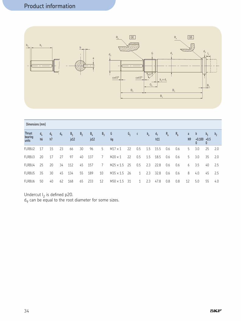
Dimensions (mm) d4 d5 d9 B1 B2 B4 B3 G G1 c ba d7 Ra Rb a b b1 b2
h6 h7 js12 js12 6g h11 N9 +0.100 +0.5 0 0
17
20
25
35
50
15
17
20
30
40
23
27
34
45
62
66
97
112
134
168
30
40
45
55
65
96
137
157
189
233
5
7
7
10
12
FLRBU2
FLRBU3
FLRBU4
FLRBU5
FLRBU6
Thrustbearingunits
22
22
25
26
31
0.5
0.5
0.5
1
1
1.5
1.5
2.3
2.3
2.3
15.5
18.5
22.8
32.8
47.8
0.6
0.6
0.6
0.6
0.8
0.6
0.6
0.6
0.6
0.8
5
5
6
8
12
3.0
3.0
3.5
4.0
5.0
25
35
40
45
55
2.0
2.0
2.5
2.5
4.0
M17 ™ 1
M20 ™ 1
M25 ™ 1.5
M35 ™ 1.5
M50 ™ 1.5
Undercut l2 is defi ned p20.d9 can be equal to the root diameter for some sizes.

35
Planetary roller screws: technical data and dimensions
Cylindrical nuts with axial play, SRC ................................................................................. 38Flanged nuts with axial play, SRF ...................................................................................... 44Preloaded cylindrical nuts, TRU/PRU ................................................................................ 50 Preloaded fl anged nuts, TRK/PRK ...................................................................................... 54
Recirculating roller screws: technical data and dimensions Cylindrical nuts with axial play, SVC ................................................................................... 64Flanged nuts with axial play, SVF ...................................................................................... 66 Preloaded cylindrical nuts, PVU ......................................................................................... 68 Preloaded fl anged nuts, PVK .............................................................................................. 70
Flanged thrust bearing unit, FLRBU ........................... 58 & 72
Standard Range: contents
5

Product information
36
Standard Range
The full range of “SR” planetary roller screws
8
4
5
6
8
9
10
12
15
16
18
20
24
25
30
35
36
40
1215
2021
2425
3036
3944
4856
6064
7580
99100
120120
150150
180210
42
Lead
, P
Nominal diameter, d
h
o
Standard programRight hand lead
4 5 5 6 5 6 5 5 6 5 6 5 6 5 6 5 6 5 6 6 5 6 5 5 5
Manufacturingpossibilitieson request
Number of starts

Product information
37
5
SKF planetary roller screws
The robust screw for long life in tough conditions has these advantages n Very high load carrying capacityn Very long lifen High rotational speed and long lead permit linear
speed up to 90 metres/minuten Planetary timing mechanism permits high acce-
leration (> 12 000 rad/sec2)n Robust design to withstand shock loadsn Choice of 3 classes of lead precisionn Planetary timing mechanism ensures correct
functioning even in adverse environments such as ice, dirt or poor lubrication
n Special and left hand leads easily availablen Special steels availablen Special surface treatments and lubrication
availablen Nut removal without losing rolling elementsn Cylindrical and fl anged nuts, with play or preloadedn Built in wipers available in all cases.
L Backlash elimination with oversize rollers:as an option under following conditions:
total lengthg –––––––––––––– ≤ 30 d0
threaded lengthg ––––––––––––––– ≤ 15 d0

Product information
38
Cylindrical nuts with axial play, SRCBacklash elimination with oversize rollers L as an option (BRC)d0 8 g 36 mm
Standard Threaded rollers Customised
L
L
L L
L
L L L L
L L
L L L
L L L L
L L L L L
d0 Ph N ltp a Nr Nmax Ca Coa Sap mn ms Is Inn Ins Zn Designation
mm mm — mm ° kN kN mm kg kg/m kgmm2/m kgmm2 kgmm2 cm3
4
5
58
6
568
10
612
51015
56
1020
69
121824
8
12
1515
20
21212121
2424
252525
30303030
3636363636
SRC 8x4
SRC 12x5
SRC 15x5SRC 15x8
SRC 20x6
SRC 21x5SRC 21x6SRC 21x8SRC 21x10
SRC 24x6SRC 24x12
SRC 25x5SRC 25x10SRC 25x15
SRC 30x5SRC 30x6SRC 30x10SRC 30x20
SRC 36x6SRC 36x9SRC 36x12SRC 36x18SRC 36x24
4
5
55
6
5555
66
555
5555
66666
500
750
975975
1300
1400140014001400
16001600
165016501650
2000200020002000
24002400240024002400
9,04
7,55
6,069,71
5,45
4,335,206,958,62
4,559,04
3,647,26
10,81
3,043,636,06
11,98
3,044,556,069,04
11,98
7
9
99
11
9999
1111
888
9999
1111111111
8
11
1110
14
11111110
1413
111110
11111110
1414141312
11,24
17,73
25,9527,43
26,83
50,5552,7754,4459,24
42,3047,65
63,2572,6379,17
91,9895,00
106,32123,28
90,4597,52
106,60114,14123,60
19,59
26,71
43,5940,78
44,86
81,9782,1878,0683,01
65,1762,34
108,23105,31106,39
178,32175,34174,36177,28
179,39174,05181,10176,57184,38
0,02
0,02
0,020,02
0,02
0,020,020,020,04
0,020,04
0,020,040,07
0,020,020,040,07
0,020,020,040,070,07
0,1
0,2
0,20,2
0,3
0,40,40,40,4
0,50,5
0,70,70,7
1,21,21,21,2
1,21,21,21,21,2
0,4
0,9
1,41,4
2,3
2,72,72,72,7
3,63,6
3,93,93,9
5,65,65,65,6
8,08,08,08,08,0
3,2
16,0
39,039,0
123,3
149,9149,9149,9149,9
255,7255,7
301,0301,0301,0
624,2624,2624,2624,2
129E1129E1129E1192E1129E1
11,4
22,9
45,245,2
71,8
141,2141,2141,2141,2
173,2173,2
321,9321,9321,9
762,4762,4762,4761,9
922,8922,8873,1873,1873,1
0,1
0,4
1,21,2
2,5
6,56,56,56,5
6,36,3
14,314,314,3
36,236,236,235,9
45,745,745,745,745,7
0,91
1,43
2,292,29
2,47
5,035,035,035,03
4,244,24
10,210,210,2
13,713,713,713,7
13,413,413,413,413,4
Designation: page 87 - Symbols: page 86

4
A
b" "
" "
B aB
d1 D3
15°
D2 D
Qw x 45° w x 45°
Hd0 d2
0,8
0,8 0,8
Product information
39
5
Wiper on request
d0 d1 d2 D A w a b H Q B D2 D3Designation g6/H7 h12 h9
mm mm mm mm mm mm mm mm mm mm mm mm mm
8,4
12,4
15,415,5
20,4
21,421,421,521,8
24,424,8
25,425,826,2
30,430,430,831,5
36,436,536,837,237,5
8
12
1515
20
21212121
2424
252525
30303030
3636363636
SRC 8x4
SRC 12x5
SRC 15x5SRC 15x8
SRC 20x6
SRC 21x5SRC 21x6SRC 21x8SRC 21x10
SRC 24x6SRC 24x12
SRC 25x5SRC 25x10SRC 25x15
SRC 30x5SRC 30x6SRC 30x10SRC 30x20
SRC 36x6SRC 36x9SRC 36x12SRC 36x18SRC 36x24
7,3
11,3
14,314,0
19,3
20,320,320,019,7
23,322,7
24,323,723,1
29,329,328,727,5
35,335,134,734,133,5
25
30
3535
40
45454545
4848
535353
64646464
6868686868
44
44
5050
50
64646464
5858
787878
85858585
8080808080
0,5
0,5
0,50,5
0,5
0,50,50,50,5
0,50,5
0,50,50,5
0,50,50,50,5
0,50,50,50,50,5
4
4
44
4
5555
55
666
6666
55555
12
12
1616
16
20202020
2020
252525
32323232
2525252525
26,5
31,5
36,536,5
41,5
47,047,047,047,0
50,050,0
55,555,555,5
66,566,566,566,5
70,070,070,070,070,0
5
5
55
5
5555
55
555
5555
55555
3
3
33
4
4444
66
666
7777
88888
21,0
25,0
30,030,0
35,0
40,540,540,540,5
42,042,0
47,047,047,0
58,058,058,058,0
62,062,062,062,062,0
13
17
2020
25
26262626
3131
323232
38383838
4545454545
Wiper recess

Product information
40
Cylindrical nuts with axial play, SRCBacklash elimination with oversize rollers L as an option (BRC)d0 39 g 64 mm
Designation: page 87 - Symbols: page 86
d0 Ph N ltp a Nr Nmax Ca Coa Sap mn ms Is Inn Ins Zn Designation
mm mm — mm ° kN kN mm kg kg/m kgmm2/m kgmm2 kgmm2 cm3
L L L L L
L L L L L L L L L L L L L L L L L L L L L L L
510152025
812182430
58
10152025
122436
101520
1218243036
3939393939
4444444444
484848484848
565656
606060
6464646464
SRC 39x5SRC 39x10SRC 39x15SRC 39x20SRC 39x25
SRC 44x8SRC 44x12SRC 44x18SRC 44x24SRC 44x30
SRC 48x5SRC 48x8SRC 48x10SRC 48x15SRC 48x20SRC 48x25
SRC 56x12SRC 56x24SRC 56x36
SRC 60x10SRC 60x15SRC 60x20
SRC 64x12SRC 64x18SRC 64x24SRC 64x30SRC 64x36
55555
66666
555555
666
555
66666
26502650265026502650
30003000300030003000
330033003300330033003300
400040004000
425042504250
46004600460046004600
2,344,676,989,27
11,53
3,304,96
7,42 9,8512,24
1,903,033,795,687,559,41
3,907,77
11,56
3,044,556,06
3,425,126,818,49
10,15
99999
1111111111
999999
111111
999
1413131111
1211111010
1414131312
121111111110
141312
111111
1414131313
129,21152,62167,64172,82174,79
130,48143,71157,74167,81165,86
198,08218,43231,54257,75265,69285,86
212,17242,22258,33
338,57373,06394,97
296,38316,72328,93318,15309,12
268,92270,93272,89260,89249,00
261,47262,87264,94266,95246,44
481,53470,61475,11486,36462,27491,04
433,12419,15424,24
779,69782,69785,66
763,30725,56689,62619,84589,38
0,020,040,070,070,07
0,040,040,070,070,07
0,020,040,040,070,070,07
0,040,070,07
0,040,070,07
0,040,070,070,070,07
2,12,12,12,12,1
1,71,7
1,7 1,7 1,7
4,24,24,24,24,24,2
3,23,23,2
7,37,37,3
5,45,25,24,94,9
9,49,49,49,49,4
11,911,911,911,911,9
14,214,214,214,214,214,2
19,319,319,3
22,222,222,2
25,325,325,325,325,3
178E1178E1178E1178E1178E1
289E1289E1289E1289E1289E1
409E1409E1409E1409E1409E1409E1
758E1758E1758E1
999E1999E1999E1
129E2129E2129E2129E2129E2
203E1203E1203E1203E1203E1
173E1173E1173E1173E1173E1
652E1652E1652E1652E1652E1652E1
500E1500E1500E1
165E2165E2164E2
106E2105E2105E2103E2103E2
124,4124,4123,6123,6123,6
119,2119,2118,3118,3118,3
370,8370,8370,8370,8370,8369,6
385,3383,1383,1
110E1110E1110E1
984,3914,0911,2771,0771,0
27,927,927,927,927,9
22,822,822,822,822,8
54,054,054,054,054,054,0
46,246,246,2
103,0103,0103,0
46,254,054,069,469,4
Standard Threaded rollers Customised
4
A
b" "
" "
B aB
d1 D3
15°
D2 D
Qw x 45° w x 45°
Hd0 d2
0,8
0,8 0,8
Product information
41
5
Wiper on requestWiper recess
d0 d1 d2 D A w a b H Q B D2 D3Designation g6/H7 h12 h9
mm mm mm mm mm mm mm mm mm mm mm mm mm
39,439,840,240,540,9
44,444,845,245,545,9
48,448,648,849,249,549,9
56,857,558,3
60,861,261,5
64,865,265,565,966,3
3939393939
4444444444
484848484848
565656
606060
6464646464
SRC 39x5SRC 39x10SRC 39x15SRC 39x20SRC 39x25
SRC 44x8SRC 44x12SRC 44x18SRC 44x24SRC 44x30
SRC 48x5SRC 48x8SRC 48x10SRC 48x15SRC 48x20SRC 48x25
SRC 56x12SRC 56x24SRC 56x36
SRC 60x10SRC 60x15SRC 60x20
SRC 64x12SRC 64x18SRC 64x24SRC 64x30SRC 64x36
38,337,737,136,535,9
43,242,742,141,540,9
47,347,146,746,145,544,9
54,753,552,3
58,758,157,5
62,762,161,560,960,3
8080808080
8080808080
100100100100100100
100100100
122122122
115115115115115
100100100100100
9090909090
127127127127127127
112112112
152152152
129129129129129
1,01,01,01,01,0
0,50,50,50,50,5
1,01,01,01,01,01,0
1,01,01,0
1,01,01,0
1,01,01,01,01,0
88888
66666
888888
888
101010
88888
4040404040
3232323232
454545454545
404040
454545
4545454545
83,083,083,083,083,0
82,582,582,582,582,5
103,0103,0103,0103,0103,0103,0
103,0103,0103,0
125,0125,0125,0
118,0118,0118,0118,0118,0
7,07,07,07,07,0
7,07,07,07,07,0
7,07,07,07,07,07,0
7,07,07,0
10,510,510,5
7,07,07,07,07,0
88888
88888
989999
999
999
1111111111
7373737373
7474747474
909090909090
939393
110110110
106106106106106
5050505050
5656565656
606060606060
666666
717171
7575757575

Product information
42
Cylindrical nuts with axial play, SRCd0 75 g 210 mm
d0 Ph N ltp a Nr Nmax Ca Coa Sap mn ms Is Inn Ins Zn Designation
mm mm — mm ° kN kN mm kg kg/m kgmm2/m kgmm2 kgmm2 cm3
Designation: page 87 - Symbols: page 86
101520
1218243642
20
24
2425
3625
30
30
757575
8080808080
99
100
120120
150150
180
210
SRC 75x10SRC 75x15SRC 75x20
SRC 80x12SRC 80x18SRC 80x24SRC 80x36SRC 80x42
SRC 99x20
SRC 100x24
SRC 120x24SRC 120x25
SRC 150x36SRC 150x25
SRC 180x30
SRC 210x30
555
66666
5
6
65
65
5
5
550055005500
60006000600060006000
7500
8000
80008000
72007200
5000
3700
2,433,644,85
2,734,105,458,159,49
3,68
4,37
3,643,79
4,373,04
3,04
2,60
111111
1313131111
11
13
1311
1311
11
11
121111
1414141313
11
14
1411
1411
11
11
504,86561,29572,26
410,27455,94485,80442,89425,64
924,86
655,81
915,021127,43
1156,921596,53
1962,34
2295,60
1486,681491,301495,87
1163,161167,631172,06999,09932,95
3090,44
1825,82
3027,054037,97
4108,096816,05
9069,02
11375,26
0,040,070,07
0,040,070,070,070,07
0,07
0,07
0,070,07
0,070,07
0,07
0,07
14,614,614,6
8,98,98,98,98,9
36,2
19,6
38,055,5
79,8155,7
397,8
542,7
34,734,734,7
39,539,539,539,539,5
60,4
61,7
88,888,8
138,7138,7
199,8
271,9
244E2244E2244E2
316E2316E2316E2316E2316E2
740E2
771E2
160E3160E3
390E3390E3
809E3
150E4
469E2469E2469E2
260E2260E2260E2252E2252E2
207E3
962E2
278E3453E3
959E3232E4
105E5
188E5
415E1415E1415E1
272E1272E1271E1229E1229E1
175E2
836E1
224E2409E2
676E2146E3
392E3
757E3
143,0143,0143,0
103,0103,0103,0132,0132,0
342,0
200,0
363,0545,0
719,01227,0
2573,0
3771,0
Standard Threaded rollers Customised

4
Product information
43
d0 d1 d2 D A w a b H Q B D2 D3Designation g6/H7 h12 h9
mm mm mm mm mm mm mm mm mm mm mm mm mm
575,876,276,5
80,881,281,582,382,7
100,5
101,5
121,5121,9
152,3151,9
182,3
212,3
757575
8080808080
99
100
120120
150150
180
210
SRC 75x10SRC 75x15SRC 75x20
SRC 80x12SRC 80x18SRC 80x24SRC 80x36SRC 80x42
SRC 99x20
SRC 100x24
SRC 120x24SRC 120x25
SRC 150x36SRC 150x25
SRC 180x30
SRC 210x30
73,773,172,5
78,778,177,576,375,7
96,5
97,5
117,5116,9
146,3146,9
176,3
206,3
150150150
140140140140140
200
180
220240
280320
420
480
191191191
156156156156156
260
195
240280
305400
515
550
1,01,01,0
1,01,01,01,01,0
1,5
1,5
2,01,5
2,03,0
3,0
3,0
101010
1010101010
16
10
1616
1632
32
40
636363
6363636363
100
63
100100
100160
160
200
153153153
143143143143143
204
183
224244
284327
427
489
10,510,510,5
10,510,510,510,510,5
15,0
10,5
15,015,0
15,015,0
20,0
20,0
101010
1212121212
12
12
1212
1313
13
20
136136136
132132132132132
180
162
196220
250280
340
385
878787
9292929292
112
116
136180
200230
250
280
A
b" "
" "
B aB
d1 D3
15°
D2 D
Qw x 45° w x 45°
Hd0 d2
0,8
0,8 0,8
Wiper on requestWiper recess

Product information
44
Flanged nuts with axial play, SRFBacklash elimination with oversize rollers L as an option (BRF)d0 8 g 36 mm
Standard Threaded rollers Customised
d0 Ph N ltp a Nr Nmax Ca Coa Sap mn ms Is Inn Ins Zn Designation
mm mm — mm ° kN kN mm kg kg/m kgmm2/m kgmm2 kgmm2 cm3
Designation: page 87 - Symbols: page 86
4
5
58
6
568
10
612
51015
56
1020
69
121824
8
12
1515
20
21212121
2424
252525
30303030
3636363636
SRF 8x4
SRF 12x5
SRF 15x5SRF 15x8
SRF 20x6
SRF 21x5SRF 21x6SRF 21x8SRF 21x10
SRF 24x6SRF 24x12
SRF 25x5SRF 25x10SRF 25x15
SRF 30x5SRF 30x6SRF 30x10SRF 30x20
SRF 36x6SRF 36x9SRF 36x12SRF 36x18SRF 36x24
4
5
55
6
5555
66
555
5555
66666
500
750
975975
1300
1400140014001400
16001600
165016501650
2000200020002000
24002400240024002400
9,04
7,55
6,069,71
5,45
4,335,206,95
8,62
4,55 9,04
3,64 7,2610,81
3,043,63
6,0611,98
3,044,55
6,06 9,0411,98
7
9
99
11
9999
1111
888
9999
1111111111
8
11
1110
14
11111110
1413
111110
11111110
1414141312
11,24
17,73
25,9527,43
26,83
50,5552,7754,4459,24
42,3047,65
63,2572,6379,17
91,9895,00
106,32123,28
90,4597,52
106,60114,14123,60
19,59
26,71
43,5940,78
44,86
81,9782,1878,0683,01
65,1762,34
108,23105,31106,39
178,32175,34174,36177,28
179,39174,05181,10176,57184,38
0,02
0,02
0,020,02
0,02
0,020,020,020,04
0,020,04
0,020,040,07
0,020,020,040,07
0,020,020,040,070,07
0,3
0,3
0,50,5
0,5
0,70,70,70,7
0,80,8
1,41,41,4
2,12,12,12,1
2,22,22,12,12,1
0,4
0,9
1,41,4
2,3
2,72,72,72,7
3,63,6
3,93,93,9
5,65,65,65,6
8,08,08,08,08,0
3,2
16,0
39,039,0
123,3
149,9149,9149,9149,9
255,7255,7
301,0301,0301,0
624,2624,2624,2624,2
129E1129E1129E1192E1129E1
66,4
106,0
201,6201,6
289,5
436,6436,6436,6436,6
524,2524,2
120E1120E1120E1
268E1268E1268E1268E1
317E1317E1312E1312E1312E1
0,1
0,4
1,21,2
2,5
6,56,56,5
6,5
6,3 6,3
14,3 14,3 14,3
36,236,2
36,2 35,9
45,745,7
45,7 45,7 45,7
0,91
1,43
2,292,29
2,47
5,035,035,035,03
4,244,24
10,210,210,2
13,713,713,713,7
13,413,413,413,413,4
L
L
L L
L
L L L L
L L
L L L
L L L L
L L L L L

4
A
r r
A2 A1
d1 D3 D2
G
Dg6/H7
D1 J
Q
u
d0 d2
0,8
0,8
D0 +0,5
Product information
45
5
d0 d1 d2 D A A1 A2 D1 J G r Q u B D2 D3Designation h12 js12 +0,4
mm mm mm mm mm mm mm mm mm mm mm mm ° mm mm mm
8,4
12,4
15,415,5
20,4
21,421,421,521,8
24,424,8
25,425,826,2
30,430,430,831,5
36,436,536,837,237,5
8
12
1515
20
21212121
2424
252525
30303030
3636363636
SRF 8x4
SRF 12x5
SRF 15x5SRF 15x8
SRF 20x6
SRF 21x5SRF 21x6SRF 21x8SRF 21x10
SRF 24x6SRF 24x12
SRF 25x5SRF 25x10SRF 25x15
SRF 30x5SRF 30x6SRF 30x10SRF 30x20
SRF 36x6SRF 36x9SRF 36x12SRF 36x18SRF 36x24
7,3
11,3
14,314,0
19,3
20,320,320,019,7
23,322,7
24,323,723,1
29,329,328,727,5
35,335,134,734,133,5
25
30
3535
40
45454545
4848
565656
64646464
6868686868
44
44
5050
50
64646464
5858
787878
85858585
8080808080
14,0
14,0
16,016,0
16,0
23,023,023,023,0
20,020,0
29,029,029,0
29,029,029,029,0
26,526,526,526,526,5
16
16
1818
18
18181818
1818
202020
27272727
2727272727
46
51
5858
63
68686868
7171
848484
97979797
102102102102102
36
41
4646
51
56565656
5959
707070
81818181
8585858585
6xM4
6xM4
6xM56xM5
6xM5
6xM56xM56xM56xM5
6xM56xM5
6xM66xM66xM6
6xM86xM86xM86xM8
6xM86xM86xM86xM86xM8
0,4
0,4
0,40,4
0,8
0,80,80,80,8
0,80,8
0,80,80,8
0,80,80,80,8
0,80,80,80,80,8
M6
M6
M6M6
M6
M6M6M6M6
M6M6
M6M6M6
M6M6M6M6
M6M6M6M6M6
30
30
3030
30
30303030
3030
303030
30303030
3030303030
3
3
33
4
4444
66
666
7777
88888
21,0
25,0
30,030,0
35,0
40,540,540,540,5
42,042,0
47,047,047,0
58,058,058,058,0
62,062,062,062,062,0
13
17
2020
25
26262626
3131
323232
38383838
4545454545
Wiper on request
Wiper recess
Equidistant

510152025
812182430
58
10152025
122436
101520
1218243036
3939393939
4444444444
484848484848
565656
606060
6464646464
SRF 39x5SRF 39x10SRF 39x15SRF 39x20SRF 39x25
SRF 44x8SRF 44x12SRF 44x18SRF 44x24SRF 44x30
SRF 48x5SRF 48x8SRF 48x10SRF 48x15SRF 48x20SRF 48x25
SRF 56x12SRF 56x24SRF 56x36
SRF 60x10SRF 60x15SRF 60x20
SRF 64x12SRF 64x18SRF 64x24SRF 64x30SRF 64x36
55555
66666
555555
666
555
66666
26502650265026502650
30003000300030003000
330033003300330033003300
400040004000
425042504250
46004600460046004600
2,34 4,67 6,98 9,2711,53
3,304,96
7,42 9,8512,24
1,903,03
3,79 5,68 7,55 9,41
3,90 7,77 11,56
3,04 4,55 6,06
3,42 5,12 6,81 8,4910,15
99999
1111111111
999999
111111
999
1413131111
1211111010
1414131312
121111111110
141312
111111
1414131313
129,21152,62167,64172,82174,79
130,48143,71157,74167,81165,86
198,08218,43231,54257,75265,69285,86
212,17242,22258,33
338,57373,06394,97
296,38316,72328,93318,15309,12
268,92270,93272,89260,89249,00
261,47262,87264,94266,95246,44
481,53470,61475,11486,36462,27491,04
433,12419,15424,24
779,69782,69785,66
763,30725,56689,62619,84589,38
0,020,040,070,070,07
0,040,040,070,070,07
0,020,040,040,070,070,07
0,040,070,07
0,040,070,07
0,040,070,070,070,07
4,04,04,04,04,0
3,63,6
3,6 3,6 3,6
7,8 7,87,87,87,87,8
6,5 6,5 6,5
12,112,112,1
11,311,211,210,910,9
9,49,49,49,49,4
11,911,911,911,911,9
14,214,214,214,214,214,2
19,319,319,3
22,222,222,2
25,325,325,325,325,3
178E1178E1178E1178E1178E1
289E1289E1289E1289E1289E1
409E1409E1409E1409E1409E1409E1
758E1758E1758E1
999E1999E1999E1
129E2129E2129E2129E2129E2
836E1836E1836E1836E1836E1
803E1803E1803E1803E1803E1
185E2185E2185E2185E2185E2185E2
213E2213E2213E2
528E2528E2528E2
502E2501E2501E2499E2499E2
124,4124,4123,6123,6123,6
119,2119,2118,3118,3118,3
370,8370,8370,8370,8370,8369,6
385,3383,1383,1
110E1110E1110E1
984,3914,0911,2771,0771,0
27,927,927,927,927,9
22,822,822,822,822,8
54,054,054,054,054,054,0
46,246,246,2
103,0 103,0
103,0
46,254,054,069,469,4
L L L L L
L L L L L L L L L L L L L L L L L L L L L L L
Product information
46
Flanged nuts with axial play, SRFBacklash elimination with oversize rollers L as an option (BRF)d0 39 g 64 mm
d0 Ph N ltp a Nr Nmax Ca Coa Sap mn ms Is Inn Ins Zn Designation
mm mm — mm ° kN kN mm kg kg/m kgmm2/m kgmm2 kgmm2 cm3
Designation: page 87 - Symbols: page 86
Standard Threaded rollers Customised

39,439,840,240,540,9
44,444,845,245,545,9
48,448,648,849,249,549,9
56,857,558,3
60,861,261,5
64,865,265,565,966,3
3939393939
4444444444
484848484848
565656
606060
6464646464
SRF 39x5SRF 39x10SRF 39x15SRF 39x20SRF 39x25
SRF 44x8SRF 44x12SRF 44x18SRF 44x24SRF 44x30
SRF 48x5SRF 48x8SRF 48x10SRF 48x15SRF 48x20SRF 48x25
SRF 56x12SRF 56x24SRF 56x36
SRF 60x10SRF 60x15SRF 60x20
SRF 64x12SRF 64x18SRF 64x24SRF 64x30SRF 64x36
38,337,737,136,535,9
43,242,742,141,540,9
47,347,146,746,145,544,9
54,753,552,3
58,758,157,5
62,762,161,560,960,3
8282828282
8282828282
105105105105105105
105105105
122122122
120120120120120
100100100100100
9090909090
127127127127127127
112112112
152152152
129129129129129
33,533,533,533,533,5
28,528,528,528,528,5
45,045,045,045,045,045,0
37,537,537,5
53,553,553,5
42,042,042,042,042,0
3333333333
3333333333
373737373737
373737
454545
4545454545
124124124124124
124124124124124
150150150150150150
150150150
180180180
180180180180180
102102102102102
102102102102102
127127127127127127
127127127
150150150
150150150150150
6xM106xM106xM106xM106xM10
6xM106xM106xM106xM106xM10
6xM126xM126xM126xM126xM126xM12
6xM126xM126xM12
6xM166xM166xM16
6xM166xM166xM166xM166xM16
1,21,21,21,21,2
1,21,21,21,21,2
1,21,21,21,21,21,2
1,21,21,2
1,61,61,6
1,61,61,61,61,6
M6M6M6M6M6
M6M6M6M6M6
M8x1M8x1M8x1M8x1M8x1M8x1
M8x1M8x1M8x1
M8x1M8x1M8x1
M8x1M8x1M8x1M8x1M8x1
3030303030
3030303030
303030303030
303030
303030
3030303030
88888
88888
999999
999
999
1111111111
73,073,073,073,073,0
7474747474
909090909090
939393
110110110
106106106106106
5050505050
5656565656
606060606060
666666
717171
7575757575
4
A
r r
A2 A1
d1 D3 D2
G
Dg6/H7
D1 J
Q
u
d0 d2
0,8
0,8
D0 +0,5
Product information
47
5
d0 d1 d2 D A A1 A2 D1 J G r Q u B D2 D3Designation h12 js12 +0,4
mm mm mm mm mm mm mm mm mm mm mm mm ° mm mm mm
Wiper on request
Wiper recess
Equidistant

Product information
48
Flanged nuts with axial play, SRFd0 75 g 210 mm
d0 Ph N ltp a Nr Nmax Ca Coa Sap mn ms Is Inn Ins Zn Designation
mm mm — mm ° kN kN mm kg kg/m kgmm2/m kgmm2 kgmm2 cm3
101520
1218243642
20
24
2425
3625
30
30
757575
8080808080
99
100
120120
150150
180
210
SRF 75x10SRF 75x15SRF 75x20
SRF 80x12SRF 80x18SRF 80x24SRF 80x36SRF 80x42
SRF 99x20
SRF 100x24
SRF 120x24SRF 120x25
SRF 150x36SRF 150x25
SRF 180x30
SRF 210x30
555
66666
5
6
65
65
5
5
550055005500
60006000600060006000
7500
8000
80008000
72007200
5000
3700
2,43 3,64 4,85
2,73 4,10 5,45
8,15 9,49
3,68
4,37
3,643,79
4,373,04
3,04
2,60
111111
1313131111
11
13
1311
1311
11
11
121111
1414141313
11
14
1411
1411
11
11
504,86561,29572,26
410,27455,94485,80442,89425,64
924,86
655,81
915,021127,43
1156,921596,53
1962,34
2295,60
1486,681491,301495,87
1163,161167,631172,06999,09932,95
3090,44
1825,82
3027,054037,97
4108,096816,05
9069,02
11375,26
0,040,070,07
0,040,070,070,070,07
0,07
0,07
0,070,07
0,070,07
0,07
0,07
20,620,620,6
17,717,717,717,717,7
48,3
29,7
51,189,0
103,3182,2
436,6
597,5
34,734,734,7
39,539,539,539,539,5
60,4
61,7
88,888,8
138,7138,7
199,8
271,9
244E2244E2244E2
316E2316E2316E2316E2316E2
740E2
771E2
160E3160E3
390E3390E3
809E3
150E4
114E3114E3114E3
108E3108E3108E3108E3108E3
449E3
259E3
598E3129E4
190E4388E4
145E5
266E5
415E1415E1415E1
272E1272E1271E1229E1229E1
175E2
836E1
224E2409E2
676E2146E3
392E3
757E3
143,0 143,0 143,0
103,0 103,0 103,0
132,0 132,0
342,0
200,0
363,0545,0
719,01227,0
2573,0
3771,0Designation: page 87 - Symbols: page 86
Standard Threaded rollers Customised

4
Product information
49
5
d0 d1 d2 D A A1 A2 D1 J G r Q u B D2 D3Designation h12 js12 +0,4
mm mm mm mm mm mm mm mm mm mm mm mm ° mm mm mm
Consult SKF
75,876,276,5
80,881,281,582,382,7
100,5
101,5
121,5121,9
152,3151,9
182,3
212,3
757575
8080808080
99
100
120120
150150
180
210
SRF 75x10SRF 75x15SRF 75x20
SRF 80x12SRF 80x18SRF 80x24SRF 80x36SRF 80x42
SRF 99x20
SRF 100x24
SRF 120x24SRF 120x25
SRF 150x36SRF 150x25
SRF 180x30
SRF 210x30
73,773,172,5
78,778,177,576,375,7
96,5
97,5
117,5116,9
146,3146,9
176,3
206,3
150150150
150150150150150
200
180
220260
280320
420
480
191191191
156156156156156
260
195
240280
305400
515
550
73,073,073,0
55,555,555,555,555,5
102,5
72,5
92,5112,5
454545
4545454545
55
50
5555
210210210
210210210210210
275
255
295340
180180180
180180180180180
245
220
260305
8xM168xM168xM16
8xM168xM168xM168xM168xM16
12xM16
12xM16
12xM1612xM16
1,61,61,6
1,61,61,61,61,6
2,4
2,4
2,42,4
M8x1M8x1M8x1
M8x1M8x1M8x1M8x1M8x1
M8x1
M8x1
M8x1M12
22°3022°3022°30
22°3022°3022°3022°3022°30
15
15
1515
101010
1212121212
12
12
1212
1313
13
20
136136136
132132132132132
180
162
196220
250280
340
385
878787
9292929292
112
116
136180
200230
250
280
A
r r
A2 A1
d1 D3 D2
G
Dg6/H7
D1 J
Q
u
d0 d2
0,8
0,8
D0 +0,5
Wiper on request
Wiper recess
Equidistant

Product information
50
Preloaded cylindrical nuts, TRU for backlash elimination PRU for optimum rigidity d0 8 g 36 mm
TRU PRU
d0 Ph N ltp a Nr Nmax Ca Coa Tpe Rng Rnr Tpr Fpr mn ms Is Inn Ins Zn
mm mm — mm ° kN kN Nm N/µm N/µm Nm N kg kg/m kgmm2/m kgmm2 kgmm2 cm3
Standard Threaded rollers Customised
4
5
58
6
568
10
612
51015
56
1020
69
121824
8
12
1515
20
21212121
2424
252525
30303030
3636363636
4
5
55
6
5555
66
555
5555
66666
400
600
750750
1050
1100110011001100
12501250
130013001300
1600160016001600
19001900190019001900
9,04
7,55
6,069,71
5,45
4,335,206,95
8,62
4,55 9,04
3,64 7,2610,81
3,043,63
6,06 11,98
3,044,55
6,06 9,0411,98
7
9
99
11
9999
1111
888
9999
1111111111
8
11
1110
14
11111110
1413
111110
11111110
1414141312
6,19
9,77
14,3015,11
14,78
27,8529,0830,0032,64
23,3126,25
34,8540,0243,62
50,6852,3458,5867,92
49,8353,7358,7362,8968,10
9,79
13,36
21,8020,39
22,43
40,9841,0939,0341,51
32,5931,17
54,1252,6553,20
89,1687,6787,1888,64
89,6987,0390,5588,2992,19
0,07
0,13
0,190,19
0,30
0,330,330,330,33
0,410,41
0,440,440,44
0,590,590,590,59
0,800,800,800,800,80
110
180
290242
290
400359311200
370150
460290180
620561420190
770530510260240
150
240
380315
380
520467404260
490200
600380230
810729550260
1000689660330310
0,06 - 0,13
0,12 - 0,25
0,18 - 0,360,18 - 0,36
0,26 - 0,58
0,31 - 0,630,31 - 0,630,31 - 0,630,31 - 0,63
0,39 - 0,780,39 - 0,78
0,42 - 0,840,42 - 0,840,42 - 0,84
0,57 - 1,130,57 - 1,130,57 - 1,130,85 - 1,41
0,77 - 1,530,77 - 1,530,77 - 1,530,77 - 1,531,15 - 1,91
236
570
932954
1305
134113941354 557
1597 541
15771008 426
184417801472 555
233419601820 707 649
0,1
0,2
0,20,2
0,3
0,40,40,40,4
0,50,5
0,70,70,7
1,21,21,21,2
1,21,21,21,21,2
0,4
0,9
1,41,4
2,3
2,72,72,72,7
3,63,6
3,93,93,9
5,65,65,65,6
8,08,08,08,08,0
3,2
16,0
39,039,0
123,3
149,9149,9149,9149,9
255,7255,7
301,0301,0301,0
624,2624,2624,2624,2
129E1129E1129E1192E1129E1
11,4
22,9
45,245,2
71,8
141,2141,2141,2141,2
173,2173,2
321,9321,9321,9
762,4762,4762,4761,9
22,8922,8873,1873,1873,1
0,1
0,4
1,21,2
2,5
6,56,56,5
6,5
6,3 6,3
14,3 14,3 14,3
36,236,2
36,2 35,9
45,745,7
45,7 45,7 45,7
0,91
1,43
2,292,29
2,47
5,035,035,035,03
4,244,24
10,210,210,2
13,713,713,713,7
13,413,413,413,413,4
Designation: page 87 - Symbols: page 86

4
A
b" "
" "
Ba
B
d1 D3
15°
D2 D
Qw x 45° w x 45°
Hd0 d2
0,8
0,8 0,8
Product information
51
5
d0 d1 d2 D A w a b H Q B D2 D3Designation g6/H7 h12 h9
mm mm mm mm mm mm mm mm mm mm mm mm mm
8,4
12,4
15,415,5
20,4
21,421,421,521,8
24,424,8
25,425,826,2
30,430,430,831,5
36,436,536,837,237,5
8
12
1515
20
21212121
2424
252525
30303030
3636363636
TRU/PRU 8x4
TRU/PRU 12x5
TRU/PRU 15x5TRU/PRU 15x8
TRU/PRU 20x6
TRU/PRU 21x5TRU/PRU 21x6TRU/PRU 21x8TRU/PRU 21x10
TRU/PRU 24x6TRU/PRU 24x12
TRU/PRU 25x5TRU/PRU 25x10TRU/PRU 25x15
TRU/PRU 30x5TRU/PRU 30x6TRU/PRU 30x10TRU/PRU 30x20
TRU/PRU 36x6TRU/PRU 36x9TRU/PRU 36x12TRU/PRU 36x18TRU/PRU 36x24
7,3
11,3
14,314,0
19,3
20,320,320,019,7
23,322,7
24,323,723,1
29,329,328,727,5
35,335,134,734,133,5
25
30
3535
40
45454545
4848
535353
64646464
6868686868
44
44
5050
50
64646464
5858
787878
85858585
8080808080
0,5
0,5
0,50,5
0,5
0,50,50,50,5
0,50,5
0,50,50,5
0,50,50,50,5
0,50,50,50,50,5
4
4
44
4
5555
55
666
6666
55555
12
12
1616
16
20202020
2020
252525
32323232
2525252525
26,5
31,5
36,536,5
41,5
47,047,047,047,0
50,050,0
55,555,555,5
66,566,566,566,5
70,070,070,070,070,0
5
5
55
5
5555
55
555
5555
55555
3
3
33
4
4444
66
666
7777
88888
21,0
25,0
30,030,0
35,0
40,540,540,540,5
42,042,0
47,047,047,0
58,058,058,058,0
62,062,062,062,062,0
13
17
2020
25
26262626
3131
323232
38383838
4545454545
Wiper on requestWiper recess

Product information
52
Preloaded cylindrical nuts, TRU for backlash elimination PRU for optimum rigidityd0 39 g 64 mm
TRU PRU
d0 Ph N ltp a Nr Nmax Ca Coa Tpe Rng Rnr Tpr Fpr mn ms Is Inn Ins Zn
mm mm — mm ° kN kN Nm N/µm N/µm Nm N kg kg/m kgmm2/m kgmm2 kgmm2 cm3
510152025
812182430
58
10152025
122436
101520
1218243036
3939393939
4444444444
484848484848
565656
606060
6464646464
55555
66666
555555
666
555
66666
21002100210021002100
24002400240024002400
260026002600260026002600
310031003100
340034003400
36503650365036503650
2,344,676,989,27
11,53
3,304,967,429,85
12,24
1,903,033,795,687,559,41
3,907,77
11,56
3,044,556,06
3,425,126,818,49
10,15
99999
1111111111
999999
111111
999
1413131111
1211111010
1414131312
121111111110
141312
111111
1414131313
71,1984,0992,3695,2296,30
71,8979,1886,9192,4691,38
109,13120,34127,57142,01146,38157,50
116,90133,45142,33
186,53205,54217,61
165,57176,93183,76177,73172,69
134,46135,46136,45130,45124,50
130,73131,44132,47133,48123,22
240,77235,30237,56243,18231,14245,52
216,56209,58212,12
389,85391,35392,83
381,65362,78344,81309,92294,69
0,920,920,920,920,92
1,121,121,121,121,12
1,301,301,301,301,301,30
1,681,681,68
1,881,881,88
2,092,092,092,092,09
750500390220210
688610430290190
1080889760600460320
810410290
1030830700
930790640440350
980650510290280
895800550380250
14101156 980 780 600 480
1060 530 370
13401080 910
12001030 840 570 450
0,88 - 1,750,88 - 1,750,88 - 1,750,88 - 1,751,31 - 2,19
1,07 - 2,141,07 - 2,141,07 - 2,141,07 - 2,141,60 - 2,68
1,24 - 2,471,24 - 2,471,24 - 2,471,24 - 2,471,24 - 2,471,24 - 2,47
1,60 - 3,191,60 - 3,192,39 - 3,99
1,79 - 3,581,79 - 3,581,79 - 3,58
1,99 - 3,981,99 - 3,981,99 - 3,981,99 - 3,981,99 - 3,98
228819651465 694697
243222971497 725727
26982583240520721423 782
29521579 910
291326352326
3328290023181292 892
2,12,12,12,12,1
1,71,7
1,7 1,7 1,7
4,24,2
4,2 4,2 4,2 4,2
3,2 3,2 3,2
7,3 7,3 7,3
5,4 5,2 5,2 4,9 4,9
9,49,49,49,49,4
11,911,911,911,911,9
14,214,214,214,214,214,2
19,319,319,3
22,222,222,2
25,325,325,325,325,3
178E1178E1178E1178E1178E1
289E1289E1289E1289E1289E1
409E1409E1409E1409E1409E1409E1
758E1758E1758E1
999E1999E1999E1
129E2129E2129E2129E2129E2
203E1203E1203E1203E1203E1
173E1173E1173E1173E1173E1
652E1652E1652E1652E1652E1652E1
500E1500E1500E1
165E2165E2164E2
106E2105E2105E2103E2103E2
124,4124,4123,6123,6123,6
119,2119,2118,3118,3118,3
370,8370,8370,8370,8370,8369,6
385,3383,1383,1
110E1110E1110E1
984,3914,0911,2771,0771,0
27,927,927,927,927,9
22,822,822,822,822,8
54,054,054,054,054,054,0
46,246,246,2
103 103 103
46,254,054,069,469,4
Designation: page 87 - Symbols: page 86
Standard Threaded rollers Customised

4
Product information
53
5
d0 d1 d2 D A w a b H Q B D2 D3Designation g6/H7 h12 h9
mm mm mm mm mm mm mm mm mm mm mm mm mm
39,439,840,240,540,9
44,444,845,245,545,9
48,448,648,849,249,549,9
56,857,558,3
60,861,261,5
64,865,265,565,966,3
3939393939
4444444444
484848484848
565656
606060
6464646464
TRU/PRU 39x5TRU/PRU 39x10TRU/PRU 39x15TRU/PRU 39x20TRU/PRU 39x25
TRU/PRU 44x8TRU/PRU 44x12TRU/PRU 44x18TRU/PRU 44x24TRU/PRU 44x30
TRU/PRU 48x5TRU/PRU 48x8 TRU/PRU 48x10TRU/PRU 48x15TRU/PRU 48x20TRU/PRU 48x25
TRU/PRU 56x12TRU/PRU 56x24TRU/PRU 56x36
TRU/PRU 60x10TRU/PRU 60x15TRU/PRU 60x20
TRU/PRU 64x12TRU/PRU 64x18TRU/PRU 64x24TRU/PRU 64x30TRU/PRU 64x36
38,337,737,136,535,9
43,242,742,141,540,9
47,347,146,746,145,544,9
54,753,552,3
58,758,157,5
62,762,161,560,960,3
8080808080
8080808080
100100100100100100
100100100
122122122
115115115115115
100100100100100
9090909090
127127127127127127
112112112
152152152
129129129129129
1,01,01,01,01,0
0,50,50,50,50,5
1,01,01,01,01,01,0
1,01,01,0
1,01,01,0
1,01,01,01,01,0
88888
66666
888888
888
101010
88888
4040404040
3232323232
454545454545
404040
454545
4545454545
83,083,083,083,083,0
82,582,582,582,582,5
103,0103,0103,0103,0103,0103,0
103,0103,0103,0
125,0125,0125,0
118,0118,0118,0118,0118,0
7,07,07,07,07,0
7,07,07,07,07,0
7,07,07,07,07,07,0
7,07,07,0
10,510,510,5
7,07,07,07,07,0
88888
88888
999999
999
999
1111111111
7337737373
7474747474
909090909090
939393
110110110
106106106106106
5050505050
5656565656
606060606060
666666
717171
7575757575
A
b" "
" "
Ba
B
d1 D3
15°
D2 D
Qw x 45° w x 45°
Hd0 d2
0,8
0,8 0,8
Wiper on requestWiper recess

Product information
54
Preloaded flanged nuts, TRK for backlash elimination PRK for optimum rigidityd0 8 g 36 mm
TRK PRK
d0 Ph N ltp a Nr Nmax Ca Coa Tpe Rng Rnr Tpr Fpr mn ms Is Inn Ins Zn
mm mm — mm ° kN kN Nm N/µm N/µm Nm N kg kg/m kgmm2/m kgmm2 kgmm2 cm3
Standard Threaded rollers Customised
4
5
58
6
568
10
612
51015
56
1020
69
121824
8
12
1515
20
21212121
2424
252525
30303030
3636363636
4
5
55
6
5555
66
555
5555
66666
400
600
750750
1050
1100110011001100
12501250
130013001300
1600160016001600
19001900190019001900
9,04
7,55
6,069,71
5,45
4,335,206,95
8,62
4,55 9,04
3,64 7,2610,81
3,043,63
6,06 11,98
3,044,55
6,06 9,0411,98
7
9
99
11
9999
1111
888
9999
1111111111
8
11
1110
14
11111110
1413
111110
11111110
1414141312
6,19
9,77
14,3015,11
14,78
27,8529,0830,0032,64
23,3126,25
34,8540,0243,62
50,6852,3458,5867,92
49,8353,7358,7362,8968,10
9,79
13,36
21,8020,39
22,43
40,9841,0939,0341,51
32,5931,17
54,1252,6553,20
89,1687,6787,1888,64
89,6987,0390,5588,2992,19
0,07
0,13
0,190,19
0,30
0,330,330,330,33
0,410,41
0,440,440,44
0,590,590,590,59
0,800,800,800,800,80
110
180
290242
290
400359311200
370150
460290180
620561420190
770530510260240
150
240
380315
380
520467404260
490200
600380230
810729550260
1000689660330310
0,06 - 0,13
0,12 - 0,25
0,18 - 0,360,18 - 0,36
0,26 - 0,58
0,31 - 0,630,31 - 0,630,31 - 0,630,31 - 0,63
0,39 - 0,780,39 - 0,78
0,42 - 0,840,42 - 0,840,42 - 0,84
0,57 - 1,130,57 - 1,130,57 - 1,130,85 - 1,41
0,77 - 1,530,77 - 1,530,77 - 1,530,77 - 1,531,15 - 1,91
236
570
932954
1305
134113941354 557
1597 541
15771008 426
184417801472 555
233419601820 707 649
0,3
0,3
0,50,5
0,5
0,70,70,70,7
0,80,8
1,41,41,4
2,12,12,12,1
2,12,12,12,12,1
0,4
0,9
1,41,4
2,3
2,72,72,72,7
3,63,6
3,93,93,9
5,65,65,65,6
8,08,08,08,08,0
3,2
16,0
39,039,0
123,3
149,9149,9149,9149,9
255,7255,7
301,0301,0301,0
624,2624,2624,2624,2
129E1129E1129E1192E1129E1
66,4
106,0
201,6201,6
289,5
436,6436,6436,6436,6
524,2524,2
120E1120E1120E1
268E1268E1268E1268E1
317E1317E1312E1312E1312E1
0,1
0,4
1,21,2
2,5
6,56,56,5
6,5
6,3 6,3
14,3 14,3 14,3
36,2 36,2
36,2 35,9
45,745,7
45,7 45,7 45,7
0,91
1,43
2,292,29
2,47
5,035,035,035,03
4,244,24
10,2010,2010,20
13,7013,7013,7013,70
13,4013,4013,4013,4013,40
Designation: page 87 - Symbols: page 86

4
A
r r
A2 A1
BB
d1 D3
15°
D2
G
Dg6/H7
D1 J
Q
u
d0 d2D0 +0,5
0,8
0,8
Product information
55
5
Wiper recess
Wiper on request
Dowel pinsto hold preload
3 Bolts for transport
d0 d1 d2 D A A1 A2 D1 J G r Q u B D2 D3Designation h12 js12 +0,4
mm mm mm mm mm mm mm mm mm mm mm mm ° mm mm mm
8,4
12,4
15,415,5
20,4
21,421,021,021,8
24,424,8
25,425,826,2
30,430,831,831,5
36,436,536,837,237,5
8
12
1515
20
21212121
2424
252525
30303030
3636363636
TRK/PRK 8x4
TRK/PRK 12x5
TRK/PRK 15x5TRK/PRK 15x8
TRK/PRK 20x6
TRK/PRK 21x5TRK/PRK 21x6TRK/PRK 21x8TRK/PRK 21x10
TRK/PRK 24x6TRK/PRK 24x12
TRK/PRK 25x5TRK/PRK 25x10TRK/PRK 25x15
TRK/PRK 30x5TRK/PRK 30x6TRK/PRK 30x10TRK/PRK 30x20
TRK/PRK 36x6TRK/PRK 36x9TRK/PRK 36x12TRK/PRK 36x18TRK/PRK 36x24
7,3
11,3
14,314,0
19,3
20,320,320,019,7
23,322,7
24,323,723,1
29,329,328,727,5
35,335,134,734,133,5
25
30
3535
40
45454545
4848
565656
64646464
6868686868
44
44
5050
50
64646464
5858
787878
85858585
8080808080
14,0
14,0
16,016,0
16,0
23,023,023,023,0
20,020,0
29,029,029,0
29,029,029,029,0
26,526,526,526,526,5
16
16
1818
18
18181818
1818
202020
27272727
2727272727
46
51
5858
63
68686868
7171
848484
98989898
102102102102102
36
41
4646
51
56565656
5959
707070
81818181
8585858585
6xM4
6xM4
6xM56xM5
6xM5
6xM56xM56xM56xM5
6xM56xM5
6xM66xM66xM6
6xM86xM86xM86xM8
6xM86xM86xM86xM86xM8
0,4
0,4
0,40,4
0,8
0,80,80,80,8
0,80,8
0,80,80,8
0,80,80,80,8
0,80,80,80,80,8
M6
M6
M6M6
M6
M6M6M6M6
M6M6
M6M6M6
M6M6M6M6
M6M6M6M6M6
30
30
3030
30
30303030
3030
303030
30303030
3030303030
3
3
33
4
4444
66
666
7777
88888
21,0
25,0
30,030,0
35,0
40,540,540,540,5
42,042,0
47,047,047,0
58,058,058,058,0
62,062,062,062,062,0
13
17
2020
25
26262626
3131
323232
38383838
4545454545
Equidistant
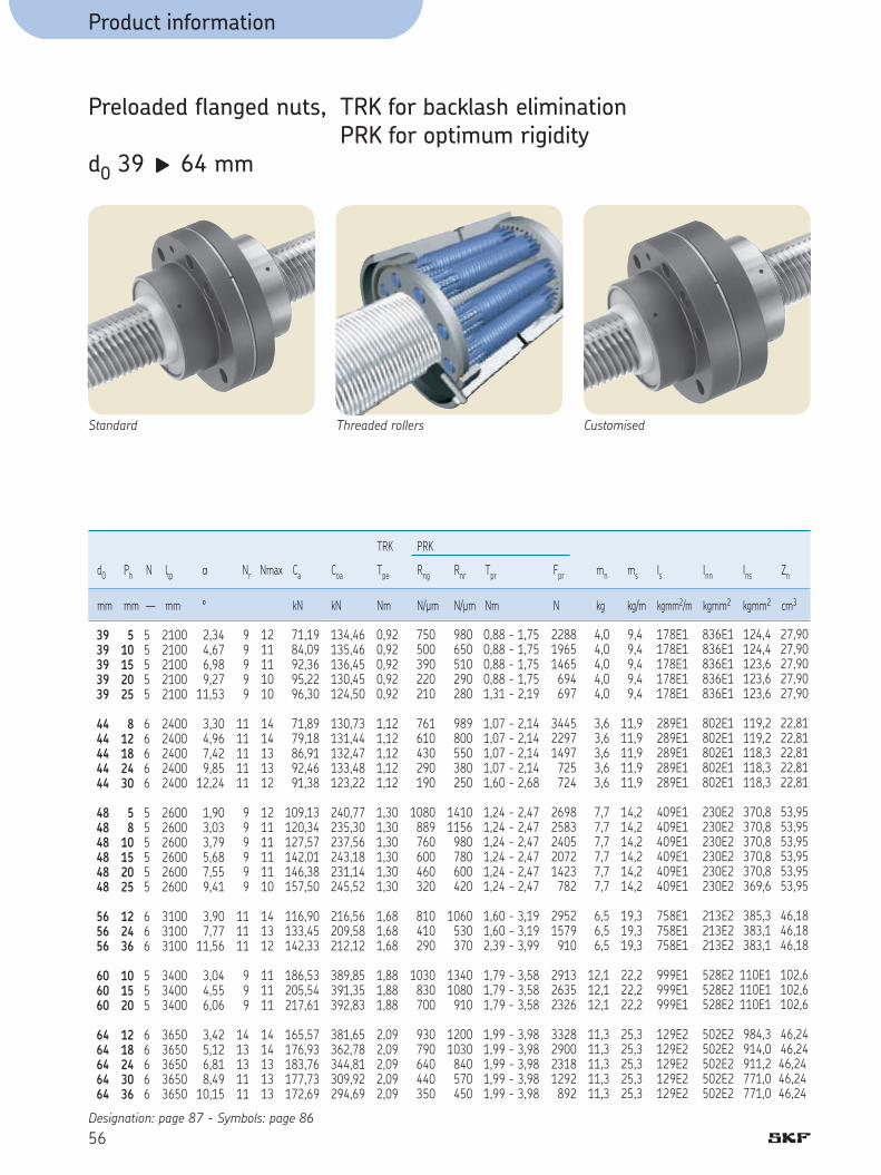
Product information
56
Preloaded flanged nuts, TRK for backlash elimination PRK for optimum rigidityd0 39 g 64 mm
TRK PRK
d0 Ph N ltp a Nr Nmax Ca Coa Tpe Rng Rnr Tpr Fpr mn ms Is Inn Ins Zn
mm mm — mm ° kN kN Nm N/µm N/µm Nm N kg kg/m kgmm2/m kgmm2 kgmm2 cm3
510152025
812182430
58
10152025
122436
101520
1218243036
3939393939
4444444444
484848484848
565656
606060
6464646464
55555
66666
555555
666
555
66666
21002100210021002100
24002400240024002400
260026002600260026002600
310031003100
340034003400
36503650365036503650
2,34 4,67 6,98 9,2711,53
3,304,96
7,42 9,8512,24
1,903,03
3,79 5,68 7,55 9,41
3,90 7,77 11,56
3,04 4,55 6,06
3,42 5,12 6,81 8,4910,15
99999
1111111111
999999
111111
999
1413131111
1211111010
1414131312
121111111110
141312
111111
1414131313
71,1984,0992,3695,2296,30
71,8979,1886,9192,4691,38
109,13120,34127,57142,01146,38157,50
116,90133,45142,33
186,53205,54217,61
165,57176,93183,76177,73172,69
134,46135,46136,45130,45124,50
130,73131,44132,47133,48123,22
240,77235,30237,56243,18231,14245,52
216,56209,58212,12
389,85391,35392,83
381,65362,78344,81309,92294,69
0,920,920,920,920,92
1,121,121,121,121,12
1,301,301,301,301,301,30
1,681,681,68
1,881,881,88
2,092,092,092,092,09
750500390220210
761610
430 290 190
1080889
760 600 460 320
810 410 290
1030 830 700
930 790 640 440 350
980650510290280
989800
550 380 250
14101156 980 780 600 420
1060 530 370
13401080 910
12001030 840 570 450
0,88 - 1,750,88 - 1,750,88 - 1,750,88 - 1,751,31 - 2,19
1,07 - 2,141,07 - 2,141,07 - 2,141,07 - 2,141,60 - 2,68
1,24 - 2,471,24 - 2,471,24 - 2,471,24 - 2,471,24 - 2,471,24 - 2,47
1,60 - 3,191,60 - 3,192,39 - 3,99
1,79 - 3,581,79 - 3,581,79 - 3,58
1,99 - 3,981,99 - 3,981,99 - 3,981,99 - 3,981,99 - 3,98
228819651465 694 697
344522971497 725 724
26982583240520721423 782
29521579 910
291326352326
3328290023181292 892
4,04,04,04,04,0
3,63,6
3,6 3,6 3,6
7,77,7
7,7 7,7 7,7 7,7
6,5 6,5
6,5
12,112,112,1
11,311,311,311,311,3
9,49,49,49,49,4
11,911,911,911,911,9
14,214,214,214,214,214,2
19,319,319,3
22,222,222,2
25,325,325,325,325,3
178E1178E1178E1178E1178E1
289E1289E1289E1289E1289E1
409E1409E1409E1409E1409E1409E1
758E1758E1758E1
999E1999E1999E1
129E2129E2129E2129E2129E2
836E1836E1836E1836E1836E1
802E1802E1802E1802E1802E1
230E2230E2230E2230E2230E2230E2
213E2213E2213E2
528E2528E2528E2
502E2502E2502E2502E2502E2
124,4124,4123,6123,6123,6
119,2119,2118,3118,3118,3
370,8370,8370,8370,8370,8369,6
385,3383,1383,1
110E1110E1110E1
984,3914,0911,2771,0771,0
27,9027,9027,9027,9027,90
22,8122,81
22,81 22,81 22,81
53,9553,95
53,95 53,95 53,95 53,95
46,1846,1846,18
102,6102,6102,6
46,24 46,24 46,24 46,24 46,24
Designation: page 87 - Symbols: page 86
Standard Threaded rollers Customised

4
Product information
57
5
d0 d1 d2 D A A1 A2 D1 J G r Q u B D2 D3Designation h12 js12 +0,4
mm mm mm mm mm mm mm mm mm mm mm mm ° mm mm mm
39,439,840,240,540,9
44,444,845,245,545,9
48,448,648,849,249,549,9
56,857,558,3
60,861,261,5
64,865,265,565,966,3
3939393939
4444444444
484848484848
565656
606060
6464646464
TRK/PRK 39x5TRK/PRK 39x10TRK/PRK 39x15TRK/PRK 39x20TRK/PRK 39x25
TRK/PRK 44x8TRK/PRK 44x12TRK/PRK 44x18TRK/PRK 44x24TRK/PRK 44x30
TRK/PRK 48x5TRK/PRK 48x8 TRK/PRK 48x10TRK/PRK 48x15TRK/PRK 48x20TRK/PRK 48x25
TRK/PRK 56x12TRK/PRK 56x24TRK/PRK 56x36
TRK/PRK 60x10TRK/PRK 60x15TRK/PRK 60x20
TRK/PRK 64x12TRK/PRK 64x18TRK/PRK 64x24TRK/PRK 64x30TRK/PRK 64x36
38,337,737,136,535,9
43,242,742,141,540,9
47,347,146,746,145,544,9
54,753,552,3
58,758,157,5
62,762,161,560,960,3
8282828282
8282828282
105105105105105105
105105105
122122122
120120120120120
100100100100100
9090909090
127127127127127127
112112112
152152152
129129129129129
33,533,533,533,533,5
28,528,528,528,528,5
454545454545
37,537,537,5
53,553,553,5
4242424242
3333333333
3333333333
373737373737
373737
454545
4545454545
124124124124124
124124124124124
150150150150150150
150150150
180180180
180180180180180
102102102102102
102102102102102
127127127127127127
127127127
150150150
150150150150150
6xM106xM106xM106xM106xM10
6xM106xM106xM106xM106xM10
6xM126xM126xM126xM126xM126xM12
6xM126xM126xM12
6xM166xM166xM16
6xM166xM166xM166xM166xM16
1,21,21,21,21,2
1,21,21,21,21,2
1,21,21,21,21,21,2
1,21,21,2
1,61,61,6
1,61,61,61,61,6
M6M6M6M6M6
M6M6M6M6M6
M8x1M8x1M8x1M8x1M8x1M8x1
M8x1M8x1M8x1
M8x1M8x1M8x1
M8x1M8x1M8x1M8x1M8x1
3030303030
3030303030
303030303030
303030
303030
3030303030
88888
88888
999999
999
999
1111111111
7373737373
7474747474
909090909090
939393
110110110
106106106106106
5050505050
5656565656
606060606060
666666
717171
7575757575
A
r r
A2 A1
BB
d1 D3
15°
D2
G
Dg6/H7
D1 J
Q
u
d0 d2D0 +0,5
0,8
0,8
Wiper recess
Wiper on request
Dowel pinsto hold preload
3 Bolts for transport
Equidistant

58
Product information
In standard version, the “FLRBU” thrust bearing unit is assembled according to drawing page 30 or 31. If you require a different assembly, please indicate it when ordering.Greased for life with SKF LGEP2.
* Preload torque measured at 50 rpm with SKF LGEP2 as lubricant.
Flanged thrust bearing units
Angular contact ball bearing (40°) Lock nut Basic load rating Number Bearings Maximum Axial Tilt High precision KMT nut (axial) of designation preload rigidity rigidity bearings torque *
Flanged Ca Coa Designation Hook Tightening Grub screwsbearing spanner torque (Nm) Size Max.unit kN kN Nm N/µm Nm/mrad Nm tighteningdesignation torque (Nm)
13,3
27.9
40.1
74.2
109.4
208.8
305,3
473,1
14,7
31.9
63.8
119.2
188.4
392.3
615,4
1123
2
2
4
4
4
4
4
4
FLRBU1
FLRBU2
FLRBU3
FLRBU4
FLRBU5
FLRBU6
FLRBU7
FLRBU8
7201 BEGBP
7303 BEGBP
7204 BEGBP
7305 BEGBP
7307 BEGBP
7310 BEGBP
7313 BEGBP 7318 BEGBP
0.10
0.25
0.25
1.10
1.10
1.50
2.00
2.30
150
190
400
450
600
750
1250
1500
40
51
140
160
715
1000
3200
7500
KMT 1
KMT 3
KMT 4
KMT 5
KMT 7
KMT 10
KMT 13
KMT 18
HN 3
HN 4
HN 5
HN 5
HN 7
HN 10
HN 14
HN 18
10
15
18
25
42
70
100
160
M5
M6
M6
M6
M6
M8
M8
M10
4,5
8
8
8
8
18
18
35
D4 D2 D5 D3 D1
L1
L2 L3
1,6E
5xS1
45°
60°x4
15°
Ø 0,2
1,6
L4
L5
Dimensions (mm) L1 L2 L3 L4 D1 D2 D3 D4 D5 S1 Fixing E L5
h7 H13 screws
42
46
77
89
110
140
180
235
10
10
13
16
20
25
30
35
25.0
32.0
60.0
68.0
82.0
98.5
133.5
179.0
14
18
18
20
22
25
28
32
76
90
90
120
140
171
225
285
50
62
59
80
99
130
170
219
47
60
60
80
100
130
170
220
63
76
74
100
120
152
198
252
30
37
40
44
54
75
95
125
6.6
6.6
9.0
11.0
13.0
13.0
17.5
22.0
FLRBU1
FLRBU2
FLRBU3
FLRBU4
FLRBU5
FLRBU6
FLRBU7
FLRBU8
Flangedbearingunitdesignation
M6 ™ 25
M6 ™ 25
M8 ™ 25
M10 ™ 30
M12 ™ 40
M12 ™ 40
M16 ™ 55
M20
27
32
32
44
54
67
87
115
12,0
18,0
30,0
36,0
47,0
58,5
53,5
99,0

59
5
Product information
Dimensions (mm) d4 d5 d9 B1 B2 B4 B3 G G1 c ba d7 Ra Rb a b b1 b2
h6 h7 js12 js12 6g h11 N9 +0.100 +0.5 0 0
12
17
20
25
35
50
65
90
10
15
17
20
30
40
60
85
17
23
27
34
45
62
78
108
58
66
97
112
134
168
210
270
20
30
40
45
55
65
100
120
78
96
137
157
189
233
310
390
5
5
7
7
10
12
18
25
FLRBU1
FLRBU2
FLRBU3
FLRBU4
FLRBU5
FLRBU6
FLRBU7
FLRBU8
Thrustbearingunits
17
22
22
25
26
31
32
39
0.5
0.5
0.5
0.5
1
1
1
1
1.5
1.5
1.5
2.3
2.3
2.3
3.0
3.0
10.5
15.5
18.5
22.8
32.8
47.8
62.2
87.2
0.4
0.6
0.6
0.6
0.6
0.8
1.2
1.6
0.4
0.6
0.6
0.6
0.6
0.8
1.0
1.2
3
5
5
6
8
12
18
25
1.8
3.0
3.0
3.5
4.0
5.0
7.0
9.0
16
25
35
40
45
55
90
100
1.5
2.0
2.0
2.5
2.5
4.0
2.5
5.0
M12 ™ 1
M17 ™ 1
M20 ™ 1
M25 ™ 1.5
M35 ™ 1.5
M50 ™ 1.5
M65 ™ 2
M90 ™ 2
Undercut l2 is defi ned p20.d9 can be equal to the root diameter for some sizes.
b1 b
a
b2
d5d4
d9 l2
B3
B1B2
B4
G1
45°
ba x d7
cx45°
G
Rb QE Ra QB
cx45°

60
Product information
Other possible bearing arrangementIn case of load acting mainly in one direction, we recommend following thrust bearings.
Ca (kN) Coa (kN) Ca (kN) Coa (kN)
FLRBU1 (*): No other possible arrangement (1+1)
FLRBU2 (*): No other possible arrangement (1+1)
FLRBU3
FLRBU4
FLRBU5
FLRBU6
FLRBU7
FLRBU8
53,3
98,6
145,3
277,3
405,5
628,3
-
-
95,7
178,8
282,6
588,6
923,1
1684,6
-
-
24,7
45,7
67,3
128,5
187,9
291,2
-
-
31,9
59,6
94,2
196,2
307,7
561,5

4
Product information
61
5
Flanged thrust bearing units
Flange Suitable for SRC & SRF Suitable for PRU & PRK thrust bearing
SKF “FLRBU” fl anged thrust bearing units can be fi tted on the screw shafts in the table below:
FLRBU1
FLRBU2
FLRBU3
FLRBU4
FLRBU5
FLRBU6
FLRBU7
FLRBU8
SR 8 ™ 4 - R4
SR 12 ™ 5 - R5SR 15 ™ 5 - R5 — SR 15 ™ 8 - R5SR 20 ™ 6 - R6
SR 24 ™ 6 - R6
SR 21 ™ 5 - R5 — SR 21 ™ 6 - R5 — SR 21 ™ 8 - R5SR 21 ™ 10 - R5SR 24 ™ 12 - R6SR 25 ™ 5 - R5 — SR 25 ™ 10 - R5 — SR 25 ™ 15 - R5
SR 30 ™ 5 - R5 — SR 30 ™ 6 - R5 — SR 30 ™ 10 - R5SR 30 ™ 20 - R5SR 36 ™ 6 - R6 — SR 36 ™ 9 - R6 — SR 36 ™ 12 - R6SR 36 ™ 18 - R6 — SR 36 ™ 24 - R6
SR 39 ™ 5 - R5 — SR 39 ™ 10 - R5 — SR 39 ™ 15 - R5SR 39 ™ 20 - R5 — SR 39 ™ 25 - R5SR 44 ™ 8 - R6 — SR 44 ™ 12 - R6 — SR 44 ™ 18 - R6SR 44 ™ 24 - R6 — SR 44 ™ 30 - R6SR 48 ™ 5 - R5 — SR 48 ™ 8 - R5 — SR 48 ™ 10 - R5 SR 56 ™ 12 - R6
SR 48 ™ 15 - R5 — SR 48 ™ 20 - R5 — SR 48 ™ 25 - R5SR 56 ™ 24 - R6 — SR 56 ™ 36 - R6SR 64 ™ 12 - R6 — SR 64 ™ 18 - R6 — SR 64 ™ 24 - R6 SR 64 ™ 30 - R6 — SR 64 ™ 36 - R6
SR 60 ™ 10 - R5 — SR 60 ™ 15 - R5 — SR 60 ™ 20 - R5SR 75 ™ 10 - R5SR 80 ™ 12 - R6 — SR 80 ™ 18 - R6 — SR 80 ™ 24 - R6SR 80 ™ 36 - R6 — SR 80 ™ 42 - R6
PR 8 ™ 4 - R4PR 12 ™ 5 - R5PR 15 ™ 5 - R5 — PR 15 ™ 8 - R5
PR 20 ™ 6 - R6PR 21 ™ 5 - R5 — PR 21 ™ 6 - R5 — PR 21 ™ 8 - R5PR 24 ™ 6 - R6 — PR 24 ™ 12 - R6
PR 21 ™ 10 - R5PR 25 ™ 5 - R5 — PR 25 ™ 10 - R5 — PR 25 ™ 15 - R5
PR 30 ™ 5 - R5 — PR 30 ™ 6 - R5 — PR 30 ™ 10 - R5PR 30 ™ 20 - R5PR 36 ™ 6 - R6 — PR 36 ™ 9 - R6 — PR 36 ™ 12 - R6PR 36 ™ 18 - R6 — PR 36 ™ 24 - R6PR 39 ™ 5 - R5PR 44 ™ 8 - R6 — PR 44 ™ 12 - R6
PR 39 ™ 10 - R5 — PR 39 ™ 15 - R5 — PR 39 ™ 20 - R5 PR 39 ™ 25 - R5PR 44 ™ 18 - R6 — PR 44 ™ 24 - R6 — PR 44 ™ 30 - R6PR 48 ™ 5 - R5 — PR 48 ™ 8 - R5PR 56 ™ 12 - R6
PR 48 ™ 10 - R5 — PR 48 ™ 15 - R5 — PR 48 ™ 20 - R5PR 48 ™ 25 - R5PR 56 ™ 24 - R6 — PR 56 ™ 36 - R6PR 60 ™ 10 - R5 — PR 60 ™ 15 - R5 — PR 60 ™ 20 - R5PR 64 ™ 12 - R6 — PR 64 ™ 18 - R6 — PR 64 ™ 24 - R6 PR 64 ™ 30 - R6 — PR 64 ™ 36 - R6

Product information
62
Standard Range
The full range of “SV” recirculating roller screws
1
2
3
4
5
Lead
, Ph
External diameter, d 1
8 10 12 16 20 25 32 40 50 63 80 100 125
Standard programRight hand lead
Manufacturing possibilitieson request

Product information
63
SKF recirculating roller screws
The fi ne screw for ultimate posi-tioning accuracy has these advantages
n 1 mm lead on screws from 8 - 50 mm diametern Fine resolutionn Choice of 3 classes of lead precisionn Minimum input torque because of their great
mechanical advantagen Simplifi cation of transmissions to improve their
performancen High load capacityn Long lifen High rigidity and reliability (no miniaturised
parts)n Special surface treatments and lubrication
availablen Cylindrical nuts with play or preloadedn Flanged nuts with play or preloaded.
L Backlash elimination with oversize rollers:as an option under following conditions:
total lengthg –––––––––––––– ≤ 30 d1
threaded lengthg ––––––––––––––– ≤ 15 d1
5

Product information
64
Cylindrical nuts with axial play, SVCNuts with or without wiper recesses (standard = without)Backlash elimination with oversize rollers L as an option (BVC)
d1 Ph N ltp a Ca Coa Sap mn ms Is Inn Ins Zn Designation
mm mm — mm ° kN kN mm kg kg/m kgmm2/m kgmm2 kgmm2 cm3
L
L L
L L
L L
L L
L L
L L
L L
L L
Standard Grooved rollers Customised
SVC 8x1
SVC 10x1SVC 10x2
SVC 12x1SVC 12x2
SVC 16x1SVC 16x2
SVC 20x1SVC 20x2
SVC 25x1SVC 25x2
SVC 32x1SVC 32x 2
SVC 40x1SVC 40x2
SVC 50x1SVC 50x2SVC 50x3SVC 50x4
SVC 63x2SVC 63x4
SVC 80x4
SVC 100x5
SVC 125x5
1
12
12
12
12
12
12
12
1234
24
4
5
5
8
10 10
12 12
16 16
20 20
25 25
32 32
40 40
50 50 50 50
63 63
80
100
125
1
12
12
12
12
12
12
11
1122
12
1
1
1
500
650 650
750 750
10501050
13001300
16501650
21502150
27002700
3500350035003500
45004500
6000
8000
8000
2,28
1,823,64
1,523,04
1,142,28
0,911,82
0,731,46
0,571,14
0,460,91
0,360,731,091,46
0,581,16
0,91
0,91
0,73
8,4
8,9 8,9
10,3 10,3
11,5 11,5
18,5 18,5
32,9 32,9
64,3 64,3
79,1 49,9
189,8 98,1153,0 98,1
185,8185,8
324,9
468,5
756,0
11,0
11,4 11,4
14,0 14,0
16,8 16,8
36,6 36,6
68,4 68,4
159,2 159,2
231,6 117,2
544,3 249,4 443,3 249,4
533,5 533,5
887,7
1376,3
2770
0,02
0,020,02
0,020,02
0,020,02
0,020,02
0,020,02
0,020,02
0,020,04
0,020,040,040,04
0,040,04
0,07
0,07
0,07
0,1
0,1 0,1
0,1 0,1
0,1 0,1
0,2 0,2
0,3 0,3
0,6 0,6
1,2 1,2
2,0 2,0 2,0 2,0
3,8 3,8
12,5
22,8
46,1
0,36
0,57 0,57
0,84 0,84
1,51 1,51
2,38 2,38
3,75 3,75
6,18 6,18
9,69 9,52
14,9814,9814,9814,98
23,9323,93
38,09
59,51
93,66
2,6
6,7 6,7
14,2 14,2
46,2 46,2
114,9114,9
284,5284,5
773,3773,3
190E1184E1
455E1455E1455E1455E1
116E2116E2
294E2
718E2
178E3
3,6
5,0 5,0
6,7 6,7
14,0 14,0
29,8 29,8
79,3 79,3
280,2280,2
878,7950,6
219E1219E1219E1219E1
646E1646E1
389E2
108E3
342E3
0,1
0,1 0,1
0,1 0,1
0,3 0,3
0,8 0,8
2,5 2,5
9,1 9,1
18,8 20,0
76,0 68,6 88,1 68,6
230,0230,0
129E1
400E1
118E2
0,72
0,950,95
1,081,08
1,431,43
1,901,90
3,573,57
6,926,92
9,5713,60
24,9024,4024,0024,40
44,3044,30
166,00
308,00
520,00Designation: page 87 - Symbols: page 86

4
A
b" "
" "
a
B
d1 D2 D2-0,3
gD
Qw x 45° w x 45°
Hd0 d2
0,8
0,8 0,8
Product information
65
5
-0,2
d1 8 g 80 : D2 -0,4
-0,4
d1 100 g 125 : D2 -0,7
d0 d1 d2 D A B w a b H Q D2Designation g6/H7 with wiper without wiper h9
recess h12 recess h12
mm mm mm mm mm mm mm mm mm mm mm mm mm
8
1010
1212
1616
2020
2525
3232
4040
50505050
6363
80
100
125
7,7
9,79,7
11,711,7
15,715,7
19,719,7
24,724,7
31,731,7
39,739,3
49,749,349,549,3
62,362,3
78,6
98,3
123,3
SVC 8x1
SVC 10x1SVC 10x2
SVC 12x1SVC 12x2
SVC 16x1SVC 16x2
SVC 20x1SVC 20x2
SVC 25x1SVC 25x2
SVC 32x1SVC 32x2
SVC 40x1SVC 40x2
SVC 50x1SVC 50x2SVC 50x3SVC 50x4
SVC 63x2SVC 63x4
SVC 80x4
SVC 100x5
SVC 125x5
7,1
9,19,1
11,111,1
15,115,1
19,119,1
24,124,1
31,131,1
39,138,2
49,148,748,648,2
61,261,2
76,4
95,5
120,5
20
2222
2424
2929
3434
4242
5454
6868
82828282
103103
141
175
220
40
4040
4040
4040
4545
5454
6767
7584
101101108101
120120
197
237
282
4
44
44
44
44
55
55
55
7777
77
10
15
15
0,2
0,20,2
0,20,2
0,50,5
0,50,5
0,50,5
1,01,0
1,01,0
1,01,01,51,0
1,01,0
1,5
2,0
3,0
2
22
22
33
33
44
44
55
6666
66
8
10
12
12
1212
1212
1212
1616
2020
2525
3232
32323532
4040
63
80
100
20,8
22,822,8
24,824,8
30,230,2
35,235,2
43,543,5
55,555,5
70,070,0
84,584,584,584,5
105,5105,5
144,0
178,0
223,0
5
55
55
55
55
55
55
55
8888
88
10
10
12
16,5
18,518,5
20,520,5
25,025,0
28,528,5
36,036,0
45,045,0
55,057,0
70,070,070,070,0
94,094,0
120,0
150,0
185,0
31
3131
3131
3131
3737
4444
5757
6372
85859285
104104
175
205
250
Wiper on request

Product information
66
Flanged nuts with axial play, SVFBacklash elimination with oversize rollers L as an option (BVF)
d1 Ph N ltp a Ca Coa Sap mn ms Is Inn Ins Zn Designation
mm mm — mm ° kN kN mm kg kg/m kgmm2/m kgmm2 kgmm2 cm3
SVF 8x1
SVF 10x1SVF 10x2
SVF 12x1SVF 12x2
SVF 16x1SVF 16x2
SVF 20x1SVF 20x2
SVF 25x1SVF 25x2
SVF 32x1SVF 32x 2
SVF 40x1SVF 40x2
SVF 50x1SVF 50x2SVF 50x3SVF 50x4
SVF 63x2SVF 63x4
SVF 80x4
SVF 100x5
SVF 125x5
L
L L
L L
L L
L L
L L
L L
L L
L L
1
12
12
12
12
12
12
12
1234
24
4
5
5
8
10 10
12 12
16 16
20 20
25 25
32 32
40 40
50 50 50 50
63 63
80
100
125
1
12
12
12
12
12
12
11
1122
12
1
1
1
500
650 650
750 750
10501050
13001300
16501650
21502150
27002700
3500350035003500
45004500
6000
8000
8000
2,28
1,823,64
1,523,04
1,142,28
0,911,82
0,731,46
0,571,14
0,460,91
0,360,731,091,46
0,581,16
0,91
0,91
0,73
8,4
8,9 8,9
10,3 10,3
11,5 11,5
18,5 18,5
32,9 32,9
64,3 64,3
79,1 49,9
189,8 98,1153,0 98,1
185,8185,8
324,9
468,5
756,0
11,0
11,4 11,4
14,0 14,0
16,8 16,8
36,6 36,6
68,4 68,4
159,2 159,2
231,6 117,2
544,3 249,4 443,3 249,4
533,5 533,5
887,7
1376,3
2770
0,02
0,020,02
0,020,02
0,020,02
0,020,02
0,020,02
0,020,02
0,020,04
0,020,040,040,04
0,040,04
0,07
0,07
0,07
0,2
0,2 0,2
0,2 0,2
0,3 0,3
0,4 0,4
0,6 0,6
1,2 1,2
2,1 2,2
3,7 3,7 3,7 3,7
6,4 6,4
17,8
33,1
62,3
0,36
0,57 0,57
0,84 0,84
1,51 1,51
2,38 2,38
3,75 3,75
6,18 6,18
9,69 9,52
14,9814,9814,9814,98
23,9323,93
38,09
59,51
93,66
2,6
6,7 6,7
14,2 14,2
46,2 46,2
114,9114,9
284,5284,5
773,3773,3
190E1184E1
455E1455E1455E1455E1
116E2116E2
294E2
718E2
178E3
47,9
47,0 47,0
63,5 63,5
100,3100,3
191,9191,9
415,8415,8
111E1111E1
312E1320E1
819E1819E1805E1819E1
201E2201E2
926E2
256E3
733E3
0,1
0,1 0,1
0,1 0,1
0,3 0,3
0,8 0,8
2,5 2,5
9,1 9,1
18,8 20,0
76,0 68,6 88,1 68,6
230,0230,0
129E1
400E1
118E2
0,72
0,950,95
1,081,08
1,431,43
1,901,90
3,573,57
6,926,92
9,5713,60
24,9024,4024,0024,40
44,3044,30
166,00
308,00
520,00Designation: page 87 - Symbols: page 86
Standard Grooved rollers Customised

4
Product information
67
5
d0 d1 d2 D A A1 A2 D1 J G r Q u D2Designation h12 js12 +0,4
mm mm mm mm mm mm mm mm mm mm mm mm ° mm
8
1010
1212
1616
2020
2525
3232
4040
50505050
6363
80
100
125
7,7
9,79,7
11,711,7
15,715,7
19,719,7
24,724,7
31,731,7
39,739,3
49,749,349,549,3
62,362,3
78,6
98,3
123,3
SVF 8x1
SVF 10x1SVF 10x2
SVF 12x1SVF 12x2
SVF 16x1SVF 16x2
SVF 20x1SVF 20x2
SVF 25x1SVF 25x2
SVF 32x1SVF 32x2
SVF 40x1SVF 40x2
SVF 50x1SVF 50x2SVF 50x3SVF 50x4
SVF 63x2SVF 63x4
SVF 80x4
SVF 100x5
SVF 125x5
7,1
9,19,1
11,111,1
15,115,1
19,119,1
24,124,1
31,131,1
39,138,2
49,148,748,648,2
61,261,2
76,4
95,5
120,5
22
2222
2525
3030
3535
4545
5656
6868
82828282
105105
140
180
220
40
4040
4040
4040
4545
5454
6767
7584
101101108101
120120
197
237
282
12,0
12,012,0
12,012,0
12,012,0
13,513,5
18,018,0
23,523,5
24,028,5
34,034,037,534,0
43,543,5
76,0
93,5
113,5
16
1616
1616
1616
1818
1818
2020
2727
33333333
3333
45
50
55
43
4343
4646
5151
5858
6868
8484
102102
124124124124
150150
200
240
310
33
3333
3636
4141
4646
5656
7070
8585
102102102102
127127
170
210
270
6xM4
6xM46xM4
6xM46xM4
6xM46xM4
6xM56xM5
6xM56xM5
6xM66xM6
6xM86xM8
6xM106xM106xM106xM10
6xM126xM12
8xM16
12xM16
12xM18
0,4
0,40,4
0,40,4
0,40,4
0,80,8
0,80,8
0,80,8
0,80,8
1,21,21,21,2
1,21,2
1,6
2,4
2,4
M6
M6M6
M6M6
M6M6
M6M6
M6M6
M6M6
M6M6
M6M6M6M6
M8x1M8x1
M8x1
M8x1
M8x1
30
3030
3030
3030
3030
3030
3030
3030
30303030
3030
22°30
15
15
16,5
18,518,5
20,520,5
25,025,0
28,528,5
36,036,0
45,045,0
55,057,0
70,070,070,070,0
94,094,0
120,0
150,0
185,0
A
r r
A2 A1
d1 D3 D2
G
Dg6/H7
D1 J
Q
u
d0 d2
0,8
0,8
D0 +0,5
Wiper on request
Wiper recess
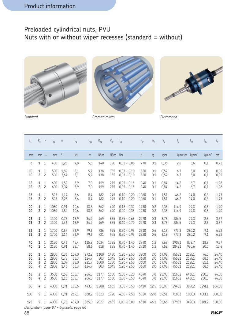
Product information
68
Preloaded cylindrical nuts, PVUNuts with or without wiper recesses (standard = without)
d1 Ph N ltp a Ca Coa Rng Rnr Tpr Fpr mn ms Is Inn Ins Zn
mm mm — mm ° kN kN N/µm N/µm Nm N kg kg/m kgmm2/m kgmm2 kgmm2 cm3
Standard Grooved rollers Customised
1
12
12
12
12
12
12
12
1234
24
4
5
5
8
10 10
12 12
16 16
20 20
25 25
32 32
40 40
50 50 50 50
63 63
80
100
125
1
12
12
12
12
12
12
11
1122
12
1
1
1
400
500 500
600 600
825 825
10501050
13001300
17001700
21502150
2800280028002800
36003600
4000
4000
4000
2,28
1,823,64
1,523,04
1,142,28
0,911,82
0,731,46
0,571,14
0,460,91
0,360,731,091,46
0,581,16
0,91
0,91
0,73
4,8
5,1 5,1
5,9 5,9
6,6 6,6
10,6 10,6
18,9 18,9
36,9 36,9
45,4 28,7
109,0 56,3 88,0 56,3
106,7106,7
186,6
269,1
434,0
5,5
5,7 5,7
7,0 7,0
8,4 8,4
18,3 18,3
34,2 34,2
79,6 79,6
115,8 58,6
272,2 124,7 221,7 124,7
266,8 266,8
443,9
688,2
1385,0
140
138138
159159
182182
362362
469469
736721
1034618
1100803
1000803
11771177
1280
1323
2027
190
185 185
215 215
245 245
490 490
635 635
995 975
1395 835
1430104513001045
15301530
1665
1720
2635
0,02 - 0,08
0,03 - 0,10 0,03 - 0,10
0,05 - 0,15 0,05 - 0,15
0,10 - 0,20 0,10 - 0,20
0,18 - 0,32 0,20 - 0,35
0,35 - 0,65 0,40 - 0,70
0,50 - 0,95 0,50 - 0,95
0,70 - 1,40 0,70 - 1,40
1,20 - 2,50 1,20 - 2,50 1,20 - 2,50 1,20 - 2,50
1,80 - 3,20 2,00 - 3,50
3,00 - 5,50
4,50 - 7,50
7,00 -10,00
770
820 820
940 940
10601060
14301430
22702270
25102320
28402710
3900366036003660
45404540
5410
5920
6510
0,1
0,1 0,1
0,1 0,1
0,1 0,1
0,2 0,2
0,3 0,3
0,6 0,6
1,2 1,2
2,0 2,0 2,0 2,0
3,8 3,8
12,5
22,8
46,1
0,36
0,57 0,57
0,84 0,84
1,51 1,51
2,38 2,38
3,75 3,75
6,18 6,18
9,69 9,52
14,9814,9814,9814,98
23,9323,93
38,09
59,51
93,66
2,6
6,7 6,7
14,2 14,2
46,2 46,2
114,9114,9
284,5284,5
773,3773,3
190E1184E1
455E1455E1455E1455E1
116E2116E2
294E2
718E2
179E3
3,6
5,0 5,0
6,7 6,7
14,0 14,0
29,8 29,8
79,3 79,3
280,2280,2
878,7950,6
219E1219E1219E1219E1
646E1646E1
389E2
108E3
342E3
0,1
0,1 0,1
0,1 0,1
0,3 0,3
0,8 0,8
2,5 2,5
9,1 9,1
18,8 20,0
76,0 68,6 81,1 68,6
230,0230,0
129E1
400E1
118E2
0,72
0,950,95
1,081,08
1,431,43
1,901,90
3,573,57
6,926,92
9,5713,6
24,4024,4024,4024,40
44,3044,30
166,00
308,00
520,00Designation: page 87 - Symbols: page 86

4
A
b" "
" "
a
d1 D2 gD
Qw x 45° w x 45°
Hd0 d2
0,8
0,8 0,8
B
D2-0,3
Product information
69
5
Wiper on request
-0,2
d1 8 g 80 : D2 -0,4
-0,4
d1 100 g 125 : D2 -0,7
4 5
d0 d1 d2 D A B w a b H Q D2Designation g6/H7 with wiper without wiper h9
recess h12 recess h12
mm mm mm mm mm mm mm mm mm mm mm mm mm
8
1010
1212
1616
2020
2525
3232
4040
50505050
6363
80
100
125
7,7
9,79,7
11,711,7
15,715,7
19,719,7
24,724,7
31,731,7
39,739,3
49,749,349,549,3
62,362,3
78,6
98,3
123,3
PVU 8x1
PVU 10x1 PVU 10x2
PVU 12x1 PVU 12x2
PVU 16x1 PVU 16x2
PVU 20x1 PVU 20x2
PVU 25x1 PVU 25x2
PVU 32x1 PVU 32x2
PVU 40x1 PVU 40x2
PVU 50x1 PVU 50x2 PVU 50x3 PVU 50x4
PVU 63x2 PVU 63x4
PVU 80x4
PVU 100x5 PVU 125x5
7,1
9,19,1
11,111,1
15,115,1
19,119,1
24,124,1
31,131,1
39,138,2
49,148,748,648,2
61,261,2
76,4
95,5
120,5
20
2222
2424
2929
3434
4242
5454
6868
82828282
103103
141
175
220
40
4040
4040
4040
4545
5454
6767
7584
101101108101
120120
197
237
282
4
44
44
44
44
55
55
55
7777
77
10
15
15
0,2
0,20,2
0,20,2
0,50,5
0,50,5
0,50,5
1,01,0
1,01,0
1,01,01,51,0
1,01,0
1,5
2,0
3,0
2
22
22
33
33
44
44
55
6666
66
8
10
12
12
1212
1212
1212
1616
2020
2525
3232
32323532
4040
63
80
100
20,8
22,822,8
24,824,8
30,230,2
35,235,2
43,543,5
55,555,5
70,070,0
84,584,584,584,5
105,5105,5
144,0
178,0
223,0
5
55
55
55
55
55
55
55
8888
88
10
10
12
16,5
18,518,5
20,520,5
25,025,0
28,528,5
36,036,0
45,045,0
55,057,0
70,070,070,070,0
94,094,0
120,0
150,0
185,0
31
3131
3131
3131
3737
4444
5757
6372
85859285
104104
175
205
250

Product information
70
Preloaded flanged nuts, PVKNuts with wiper recesses
d1 Ph N ltp a Ca Coa Rng Rnr Tpr Fpr mn ms Is Inn Ins Zn
mm mm — mm ° kN kN N/µm N/µm Nm N kg kg/m kgmm2/m kgmm2 kgmm2 cm3
Standard Grooved rollers Customised
1
12
12
12
12
12
12
12
1234
24
4
5
5
8
10 10
12 12
16 16
20 20
25 25
32 32
40 40
50 50 50 50
63 63
80
100
125
1
12
12
12
12
12
12
11
1122
12
1
1
1
400
500 500
600 600
825 825
10501050
13001300
17001700
21502150
2800280028002800
36003600
4000
4000
4000
2,28
1,823,64
1,523,04
1,142,28
0,911,82
0,731,46
0,571,14
0,460,91
0,360,731,091,46
0,581,16
0,91
0,91
0,73
4,8
5,1 5,1
5,9 5,9
6,6 6,6
10,6 10,6
18,9 18,9
36,9 36,9
45,4 28,7
109,0 56,3 88,0 56,3
106,7106,7
186,6
269,1
434,0
5,5
5,7 5,7
7,0 7,0
8,48,4
18,3 18,3
34,2 34,2
79,6 79,6
115,8 58,6
272,2 124,7 221,7124,7
266,8 266,8
443,9
688,2
1385,0
190
185 185
215 215
245 245
490 490
635 635
995 975
1395 835
1430104513001045
15301530
1665
1720
2635
255
250250
290290
330330
660660
855855
13451315
18851125
1930141017551410
20652065
2250
2320
3555
0,02 - 0,08
0,03 - 0,100,03 - 0,10
0,05 - 0,150,05 - 0,15
0,10 - 0,200,10 - 0,20
0,18 - 0,320,20 - 0,35
0,35 - 0,650,40 - 0,70
0,50 - 0,950,50 - 0,95
0,70 - 1,400,70 - 1,40
1,20 - 2,501,20 - 2,501,20 - 2,501,20 - 2,50
1,80 - 3,202,00 - 3,50
3,00 - 5,50
4,50 - 7,50
7,00 -10,00
770
820 820
940 940
10601060
14301430
22702270
25102320
28402710
3900366036003660
45404540
5410
5920
6510
0,2
0,2 0,2
0,2 0,2
0,3 0,3
0,4 0,4
0,6 0,6
1,2 1,2
2,1 2,2
3,7 3,7 3,7 3,7
6,4 6,4
17,8
33,1
62,3
0,36
0,57 0,57
0,84 0,84
1,51 1,51
2,38 2,38
3,75 3,75
6,18 6,18
9,69 9,52
14,9814,9814,9814,98
23,9323,93
38,09
59,51
93,66
2,6
6,7 6,7
14,2 14,2
46,2 46,2
114,9114,9
284,5284,5
773,3773,3
190E1184E1
455E1455E1455E1455E1
116E2116E2
294E2
718E2
179E3
47,9
47,0 47,0
63,5 63,5
100,3100,3
191,9191,9
415,8415,8
111E1111E1
312E1320E1
819E1819E1805E1819E1
201E2201E2
926E2
256E3
733E3
0,1
0,1 0,1
0,1 0,1
0,3 0,3
0,8 0,8
2,5 2,5
9,1 9,1
18,8 20,0
76,0 68,6 81,1 68,6
230,0230,0
129E1
400E1
118E2
0,72
0,950,95
1,081,08
1,431,43
1,901,90
3,573,57
6,926,92
9,5713,6
24,4024,4024,4024,40
44,3044,30
166,00
308,00
520,00Designation: page 87 - Symbols: page 86

4
A
r r
A2 A1
d1 D2
G
Dg6/H7
D1d0 d2D0 +0,5
0,8
0,8
J
Q
u
J
Q
u
Product information
71
5
d0 d1 d2 D A A1 A2 D1 J G r Q u D2Designation h12 js12 +0,4
mm mm mm mm mm mm mm mm mm mm mm mm ° mm
PVK 8x1
PVK 10x1PVK 10x2
PVK 12x1PVK 12x2
PVK 16x1PVK 16x2
PVK 20x1PVK 20x2
PVK 25x1PVK 25x2
PVK 32x1PVK 32x2
PVK 40x1PVK 40x2
PVK 50x1PVK 50x2PVK 50x3PVK 50x4
PVK 63x2PVK 63x4
PVK 80x4
PVK 100x5
PVK 125x5
8
1010
1212
1616
2020
2525
3232
4040
50505050
6363
80
100
125
7,7
9,79,7
11,711,7
15,715,7
19,719,7
24,724,7
31,731,7
39,739,3
49,749,349,549,3
62,362,3
78,6
98,3
123,3
7,1
9,19,1
11,111,1
15,115,1
19,119,1
24,124,1
31,131,1
39,138,2
49,148,748,648,2
61,261,2
76,4
95,5
120,5
22
2222
2525
3030
3535
4545
5656
6868
82828282
105105
140
180
220
40
4040
4040
4040
4545
5454
6767
7584
101101108101
120120
197
237
282
12,0
12,012,0
12,012,0
12,012,0
13,513,5
18,018,0
23,523,5
24,028,5
34,034,037,534,0
43,543,5
76,0
93,5
113,5
16
1616
1616
1616
1818
1818
2020
2727
33333333
3333
45
50
55
43
4343
4646
5151
5858
6868
8484
102102
124124124124
150150
200
240
310
33
3333
3636
4141
4646
5656
7070
8585
102102102102
127127
170
210
270
6xM4
6xM46xM4
6xM46xM4
6xM46xM4
6xM56xM5
6xM56xM5
6xM66xM6
6xM86xM8
6xM106xM106xM106xM10
6xM126xM12
8xM16
12xM16
12xM18
0,4
0,40,4
0,40,4
0,40,4
0,80,8
0,80,8
0,80,8
0,80,8
1,21,21,21,2
1,21,2
1,6
2,4
2,4
M6
M6M6
M6M6
M6M6
M6M6
M6M6
M6M6
M6M6
M6M6M6M6
M8x1M8x1
M8x1
M8x1
M8x1
30
3030
3030
3030
3030
3030
3030
3030
30303030
3030
22°30
15
15
16,5
18,518,5
20,520,5
25,025,0
28,528,5
36,036,0
45,045,0
55,057,0
70,070,070,070,0
94,094,0
120,0
150,0
185,0
Wiper recess
Wiper on request Dowel pinsto hold preload
3 Bolts for transport
key to hold preload
PVK: d1 8 g 63
PVK: d1 80 g 125
4 Bolts for transport
Equidistant

72
Product information
In standard version, the “FLRBU” thrust bearing unit is assembled according to drawing page 30 or 31. If you require a different assembly, please indicate it when ordering.Greased for life with SKF LGEP2.
* Preload torque measured at 50 rpm with SKF LGEP2 as lubricant.
Flanged thrust bearing units
Angular contact ball bearing (40°) Lock nut Basic load rating Number Bearings Maximum Axial Tilt High precision KMT nut (axial) of designation preload rigidity rigidity bearings torque *
Flanged Ca Coa Designation Hook Tightening Grub screwsbearing spanner torque (Nm) Size Max.unit kN kN Nm N/µm Nm/mrad Nm tighteningdesignation torque (Nm)
13,3
27.9
40.1
74.2
109.4
208.8
305,3
473,1
14,7
31.9
63.8
119.2
188.4
392.3
615,4
1123
2
2
4
4
4
4
4
4
FLRBU1
FLRBU2
FLRBU3
FLRBU4
FLRBU5
FLRBU6
FLRBU7
FLRBU8
7201 BEGBP
7303 BEGBP
7204 BEGBP
7305 BEGBP
7307 BEGBP
7310 BEGBP
7313 BEGBP 7318 BEGBP
0.10
0.25
0.25
1.10
1.10
1.50
2.00
2.30
150
190
400
450
600
750
1250
1500
40
51
140
160
715
1000
3200
7500
KMT 1
KMT 3
KMT 4
KMT 5
KMT 7
KMT 10
KMT 13
KMT 18
HN 3
HN 4
HN 5
HN 5
HN 7
HN 10
HN 14
HN 18
10
15
18
25
42
70
100
160
M5
M6
M6
M6
M6
M8
M8
M10
4,5
8
8
8
8
18
18
35
D4 D2 D5 D3 D1
L1
L2 L3
1,6E
5xS1
45°
60°x4
15°
Ø 0,2
1,6
L4
L5
Dimensions (mm) L1 L2 L3 L4 D1 D2 D3 D4 D5 S1 Fixing E L5
h7 H13 screws
42
46
77
89
110
140
180
235
10
10
13
16
20
25
30
35
25.0
32.0
60.0
68.0
82.0
98.5
133.5
179.0
14
18
18
20
22
25
28
32
76
90
90
120
140
171
225
285
50
62
59
80
99
130
170
219
47
60
60
80
100
130
170
220
63
76
74
100
120
152
198
252
30
37
40
44
54
75
95
125
6.6
6.6
9.0
11.0
13.0
13.0
17.5
22.0
FLRBU1
FLRBU2
FLRBU3
FLRBU4
FLRBU5
FLRBU6
FLRBU7
FLRBU8
Flangedbearingunitdesignation
M6 ™ 25
M6 ™ 25
M8 ™ 25
M10 ™ 30
M12 ™ 40
M12 ™ 40
M16 ™ 55
M20
27
32
32
44
54
67
87
115
12,0
18,0
30,0
36,0
47,0
58,5
53,5
99,0

73
5
Product information
Dimensions (mm) d4 d5 d9 B1 B2 B4 B3 G G1 c ba d7 Ra Rb a b b1 b2
h6 h7 js12 js12 6g h11 N9 +0.100 +0.5 0 0
12
17
20
25
35
50
65
90
10
15
17
20
30
40
60
85
17
23
27
34
45
62
78
108
58
66
97
112
134
168
210
270
20
30
40
45
55
65
100
120
78
96
137
157
189
233
310
390
5
5
7
7
10
12
18
25
FLRBU1
FLRBU2
FLRBU3
FLRBU4
FLRBU5
FLRBU6
FLRBU7
FLRBU8
Thrustbearingunits
17
22
22
25
26
31
32
39
0.5
0.5
0.5
0.5
1
1
1
1
1.5
1.5
1.5
2.3
2.3
2.3
3.0
3.0
10.5
15.5
18.5
22.8
32.8
47.8
62.2
87.2
0.4
0.6
0.6
0.6
0.6
0.8
1.2
1.6
0.4
0.6
0.6
0.6
0.6
0.8
1.0
1.2
3
5
5
6
8
12
18
25
1.8
3.0
3.0
3.5
4.0
5.0
7.0
9.0
16
25
35
40
45
55
90
100
1.5
2.0
2.0
2.5
2.5
4.0
2.5
5.0
M12 ™ 1
M17 ™ 1
M20 ™ 1
M25 ™ 1.5
M35 ™ 1.5
M50 ™ 1.5
M65 ™ 2
M90 ™ 2
Undercut l2 is defi ned p20.d9 can be equal to the root diameter for some sizes.
b1 b
a
b2
d5d4
d9 l2
B3
B1B2
B4
G1
45°
ba x d7
cx45°
G
Rb QE Ra QB
cx45°

74
Product information
Other possible bearing arrangementIn case of load acting mainly in one direction, we recommend following thrust bearings.
Ca (kN) Coa (kN) Ca (kN) Coa (kN)
FLRBU1 (*): No other possible arrangement (1+1)
FLRBU2 (*): No other possible arrangement (1+1)
FLRBU3
FLRBU4
FLRBU5
FLRBU6
FLRBU7
FLRBU8
53,3
98,6
145,3
277,3
405,5
628,3
-
-
95,7
178,8
282,6
588,6
923,1
1684,6
-
-
24,7
45,7
67,3
128,5
187,9
291,2
-
-
31,9
59,6
94,2
196,2
307,7
561,5
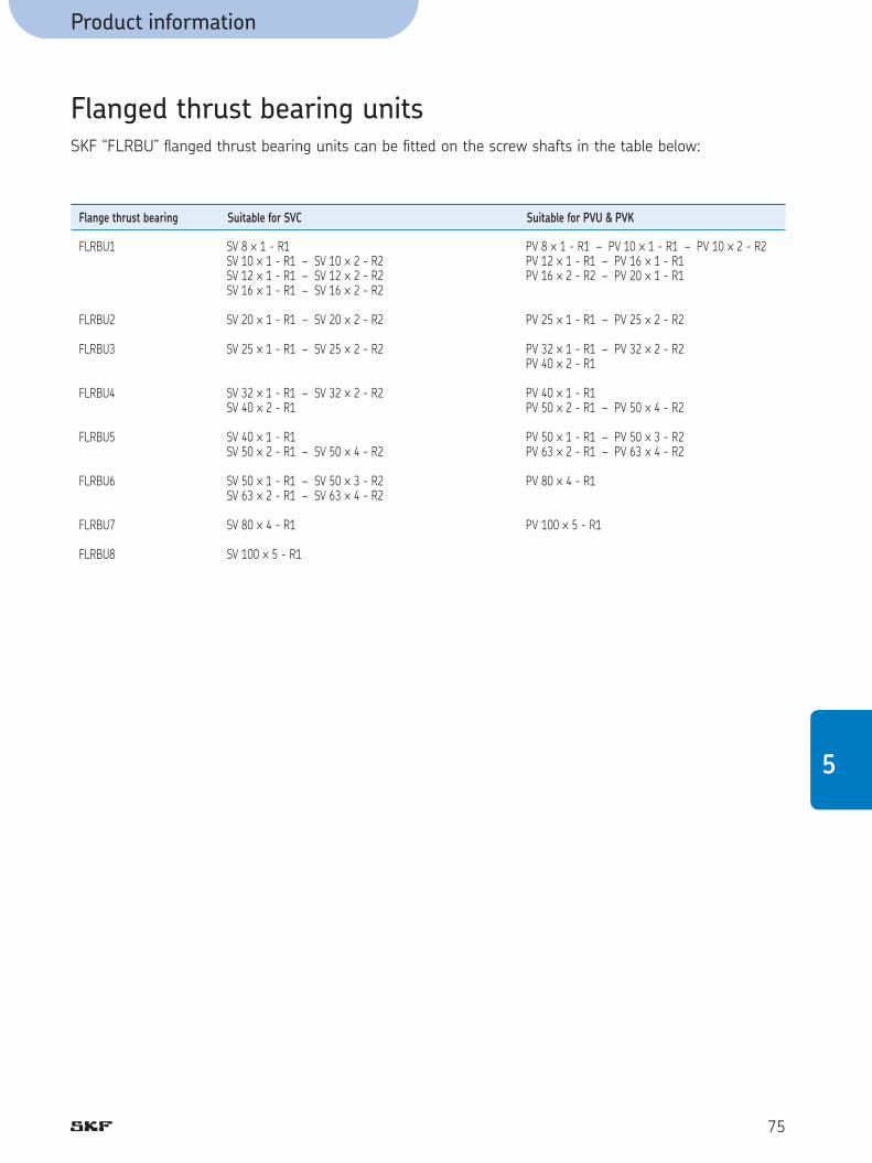
75
5
Product information
Flanged thrust bearing units
Flange thrust bearing Suitable for SVC Suitable for PVU & PVK
SKF “FLRBU” fl anged thrust bearing units can be fi tted on the screw shafts in the table below:
FLRBU1
FLRBU2
FLRBU3
FLRBU4
FLRBU5
FLRBU6
FLRBU7
FLRBU8
SV 8 ™ 1 - R1 SV 10 ™ 1 - R1 – SV 10 ™ 2 - R2 SV 12 ™ 1 - R1 – SV 12 ™ 2 - R2 SV 16 ™ 1 - R1 – SV 16 ™ 2 - R2 SV 20 ™ 1 - R1 – SV 20 ™ 2 - R2 SV 25 ™ 1 - R1 – SV 25 ™ 2 - R2 SV 32 ™ 1 - R1 – SV 32 ™ 2 - R2 SV 40 ™ 2 - R1 SV 40 ™ 1 - R1 SV 50 ™ 2 - R1 – SV 50 ™ 4 - R2 SV 50 ™ 1 - R1 – SV 50 ™ 3 - R2 SV 63 ™ 2 - R1 – SV 63 ™ 4 - R2 SV 80 ™ 4 - R1
SV 100 ™ 5 - R1
PV 8 ™ 1 - R1 – PV 10 ™ 1 - R1 – PV 10 ™ 2 - R2 PV 12 ™ 1 - R1 – PV 16 ™ 1 - R1 PV 16 ™ 2 - R2 – PV 20 ™ 1 - R1 PV 25 ™ 1 - R1 – PV 25 ™ 2 - R2 PV 32 ™ 1 - R1 – PV 32 ™ 2 - R2 PV 40 ™ 2 - R1 PV 40 ™ 1 - R1 PV 50 ™ 2 - R1 – PV 50 ™ 4 - R2 PV 50 ™ 1 - R1 – PV 50 ™ 3 - R2 PV 63 ™ 2 - R1 – PV 63 ™ 4 - R2 PV 80 ™ 4 - R1 PV 100 ™ 5 - R1

Product information
76
Ultra Power rangeThe SKF Ultra Power range is designed for heavy loads and long life.
High load capacities
SKF Ultra Power range of Plane-tary Roller Screws has been optimised to provide the maxi-mum possible life within a compact space envelope. This has resulted in an in-crease in capacity of up to 60 % over the standard product. Load capacity is independent of lead. To attain L10 life performance a mean working load of up to 80 % of Ca is allowed (50 % for HRP/HRC 60).
The maximum load should not be applied on the mounting bolts but on the fl ange. For each screw assembly size, you fi nd in the table page 78 two different values for the dynamic load capacity (Ca) according to the maximum load applied: - the Ca capacity in black is valid for max. efforts up to 80 % of the table value (diameter 60 excep-ted, which is 50 % of the value) - the Ca capacitiy in blue -higher- is valid for max. efforts ≤ Fa
Example:
HRP 120 x 20 • heavy press application - Fmax = 600 kN - Ca = 1192 kN
• plastic injection application - Fmax = 300 kN - Ca = 1550 kN
Designation HRC: cylindrical nut HRP: nut with non-central fl ange HRF: nut with central fl ange

Short strokes/oscillation performanceThe kinematics of all SKF Plane-tary Roller Screws provides continuous rolling of the working elements without recirculation. This means they are highly reliable in high load applications where there are short strokes and rapid and or many changes of direction.
Axial playAssemblies are available with an axial play less than 0,07 mm (0,1 for a 40 mm lead). Preload is not available.
Lead precision
Standard lead precision is G5.
Speed - EnvironmentAll SKF Planetary Roller Screws are rated to a maximum N ™ d0 value of 160.000. Their rollers are further controlled by plane-tary gears which help maintain rolling under extreme condition of speed and/or contamination. The rolling performance provides low noise operation. For maxi-mum speed under heavy load, please contact SKF for advice.
WipersStandard version includes wipers(WPR in the designation).Screws can be delivered without wipers on request (NOWPR).
Lubrication
Because of the heavy loads and high duty, special care must be made in the choice of lubricant. Please contact SKF for advice.
ApplicationsThe “Ultra Power Range” offers the power of hydraulic actuators combined with the precision and fl exibility of electric control, for example:• injection molding machines for
plastic and rubber• presses • broaching machines• the steel industry including
casting & rolling• friction welding• hydro-electric plants• actuators.
Product information
77
5

Product information
78
Designation Ph
d0 15 20 25 30 35 40
mm mm mm mm mm mm mm
60,0 75,0 87,0 99,0 112,5 120,0 135,0 150,0 180,0
• • • • • • • • •
• • • • • • • • •
• • • • • • • • •
• • • • • • • • •
• • • • • •
• • • •
HRP/HRC/HRF60HRP/HRC/HRF75HRP/HRC/HRF87HRP/HRC/HRF99HRP/HRC/HRF112,5HRP/HRC/HRF120HRP/HRC/HRF135HRP/HRC/HRF150HRP/HRC/HRF180
Nota: Roller screw right hand unless specified If there is a flange on the shaft, please contact SKF.
Dynamic and static loads are given for the 15 mm lead.Root diameter is given for the 15 mm lead.Outside diameter is given for the maximum lead.
Special data for HRC Designation d0 Mn Inn Ins
mm kg kgmm2 kgmm2
60,0 75,0 87,0 99,0 112,5 120,0 135,0 150,0 180,0
91626405864
108163440
187 E2517 E2111 E3220 E3423 E3516 E3118 E4235 E4108 E5
168 E1513 E1106 E2204 E2371 E2472 E2942 E2160 E3437 E3
HRC 60HRC 75HRC 87HRC 99HRC 112,5HRC 120HRC 135HRC 150HRC 180
Special data for HRF/HRP Designation d0 Mn Inn Ins
mm kg kgmm2 kgmm2
60,0 75,0 87,0 99,0 112,5 120,0 135,0 150,0 180,0
132031466673
122180470
297 E2734 E2149 E3288 E3552 E3676 E3150 E4290 E4122 E5
168 E1513 E1106 E2204 E2371 E2472 E2942 E2160 E3437 E3
HRF/HRP 60HRF/HRP 75HRF/HRP 87HRF/HRP 99HRF/HRP 112,5HRF/HRP 120HRF/HRP 135HRF/HRP 150HRF/HRP 180
Designation Load capacities if max. Load capacities if max. operating load ≤ Fa operating load > Fa d0 Fa Ca Coa Ca Coa Max length Root Outside Ms Is ltp Ø d2 Ø d1
mm kN kN kN kN kN mm mm mm kg/m kgmm2/m
60,0 75,0 87,0 99,0 112,5 120,0 135,0 150,0 180,0
90130180240290320410480750
544771979
123114251550184721603017
12061855264535034327463560287182
11939
495643816985
11401192142116002235
12061855264535034327463560287182
11939
4250 5500 6000 7500 7500 8000 8000 7200 5000
58,1 73,1 85,1 97,1 110,6 118,1 133,1 148,1 178,1
62,3 77,3 89,3 101,7 115,2 123,0 138,0 153,0 183,0
22,234,745,860,476,888,8
113,3138,7199,8
999 E1244 E2428 E2740 E2120 E3160 E3261 E3390 E3809 E3
HRP/HRC/HRF60HRP/HRC/HRF75HRP/HRC/HRF87HRP/HRC/HRF99HRP/HRC/HRF112,5HRP/HRC/HRF120HRP/HRC/HRF135HRP/HRC/HRF150HRP/HRC/HRF180

Product information
79
Designation Nut Flange w ™ 45° axbxl H Q’ D3 D A A1 A3 B Zn D1 A2 Q u N d J G
mm mm g6 mm mm mm cm3 mm mm mm ° n mm js12
1.0 1.0 1.5 1.5 1.5 1.5 2.0 3.0 3.0
HRP/HRC/HRF60HRP/HRC/HRF75HRP/HRC/HRF87HRP/HRC/HRF99HRP/HRC/HRF112,5HRP/HRC/HRF120HRP/HRC/HRF135HRP/HRC/HRF150HRP/HRC/HRF180
10x8x56 10x8x63 12x8x10016x10x100
16x10x100 16x10x100 28x16x120 32x18x160 32x18x160
M8x1 M8x1 M8x1 M8x1 M12x1,75 M12x1,75 M12x1,75 M12x1,75 M12x1,75
125 153 178 204 234 244 286 327 407
11 11 12 15 15 15 15 15 20
71 87 103 112 140 180 180 230 250
122 150 175 200 230 240 280 320 390
171 213 245 280 300 330 370 412 558
25 30 35 40 50 50 60 65 96
40 40 40 40 40 60 80 80 100
9,0 10,0 12,0 12,0 12,0 12,0 11,5 12,5 15,0
90 170 270 400 550 700 980 1350 2500
166 195 220 245 286 296 345 385 470
30 35 40 50 50 55 60 70 90
22,5 15,0 15,0 15,0 15,0 15,0 15,0 15,0 15,0
8 12 12 12 12 12 12 12 12
13,5 13,5 13,5 13,5 18,0 18,0 20,0 20,0 24,0
146 174 200 224 260 270 315 355 433
M12 M12 M12 M12 M16 M16 M18 M18 M22
Nota: Flanges to customer design on request.
5
u
Ø D
2
Ø D
1
Ø D
(+0.
5/0)
Ø D
3
Ø D
A3
A2A1
A
B
B
HRP
l" "BB
ØD ØD3
H
A
A/2w x 45° w x 45°
15°
HRC
Wiper Wiper
Key a™b™l
Lubrication
Wiper Wiper
Lubrication: Q
n ™ Holes Ø don Ø Jfor screw G

80
Electro-mechanical cylinders They are designed for long life, high acceleration and high force applications. The cylinders use brushless servomotor
technology, with an in-line direct drive as standard. SKF high performance electro-mechanical
cylinders using planetary roller screws are expanding the limits of linear
actuators (see catalogue n° 5338).
The new Standard for high performance motion
Compact Electro-Mechanical Cylinders (CEMC) are designed to
deliver the combination of a dynamic fl exible actuation packaged with powerful performance.
Cylinders for heavy loads High loads and heavy working
cycles: long life in adverse environments such as in steel industry.
The roller screw converts rotary motion into linear movement.

81
4
g
Notes

82
g
Notes

83
SKF high effi ciency screws are available from:
Australia
SKF Special Products Division17-21 Stamford RoadOAKLEIGH (Melbourne), Victoria 3166Telephone: +61 3 9567 2800Telefax: +61 3 9567 2869
Benelux
SKF Multitec Benelux B.V.P.O. Box 2350 - Kelvinbaan 16NL 3439 MT NIEUWEGEINTelephone: +31 30 60 29029Telefax: +31 30 60 29028
Czech Republic
SKF Loziska A.S.U meštanského pivovaru 7Poštovni schránka 19CZ - 170 04 PRAHA 7 - HolešoviceTelephone: +420 234 642 111Telefax: +420 234 642 415
Danmark
SKF Multitec Magnoliavej 12C5250 ODENSE SVTelephone: +45 65 92 77 77Telefax: +45 65 92 74 77
Deutschland
SKF Linearsysteme GmbHVertrieb DeutschlandParis-Straße 1D - 97424 SchweinfurtTelephone: +49 9721 657-0Telefax: +49 9721 657-111
España
SKF Productos Industriales, S.A.Pol. de l’Est - Cobalt, n°7008940 Cornellà de LlobregatES - BARCELONATelephone: +34 93 377 99 77Telefax: +34 93 474 20 39
France
SKF EquipementsBP 83F - 78180 MONTIGNY-LE-BRE-TONNEUXTelephone: +33 1 30 12 73 00Telefax: +33 1 30 12 69 09
Hungary
SKF Svéd GolyóscsapágyPF 52 - Csata u. 25HU - 2040 BUDAORSTelephone: +36 23 445 200Telefax: +36 23 445 201
India
Skefko India Bearing Company LtdP.O. Box 2202BOMBAY, 400 002Telephone: +91 22 201 3567Telefax: +91 22 208 9074
Italia
SKF Multitec S.p.A.Corso Giulio Cesare, 424/2910156 TorinoTelephone: +39 011 22 49 01Telefax: +39 011 22 49 233
Japan
SKF Japan Ltd1-9-1 Shiba Daimon, Minato-ku,Tokyo 105-0012 JAPANTelephone: +81 3 3436 4129Telefax: +81 3 3578 1014
New Zealand
SKF New Zealand LtdP.O. Box 58-549Greenmount, East TamakiAUCKLAND 1701Telephone: +64 9 274 0056Telefax: +64 9 274 5175
Norge
SKF Multitec ASPostboks 7, Lindeberg GärdN-1007 OSLO 10Telephone: +47 22 30 71 70Telefax: +47 22 30 28 14
North America
SKF Motion Technologies1530 Valley Center ParkwayUSA - BETHLEHEM, PA 18017Telephone: +1 610 861 4800 Telefax: +1 610 861 3716
Österreich
SKF Österreich AGTriester Str. 14AT - 2351 Wr. NEUDORFTelephone: +43 2236 6709 0Telefax: +43 2236 6709 220
Portugal
Sociedade SKF LimitadaPraça da Alegria, 66-AP - 1200 LISBOA Telephone: +351 1 424 7000Telefax: +351 1 417 3649
Republic of South Africa
SKF South Africa (Pty) LtdP.O. Box 13157SA - WITFIELD 1467 Telephone: +27 11 821 3542Telefax: +27 11 821 3505
Schweiz/Suisse
SKF SchweizEschenstrasse 5CH - 8603 SCHWERZENBACHTelephone: +41 44 825 81 81Telefax: +41 44 825 82 82
Suomi / Finland
SKF MultitecPL 60 - Luomannotko 3FIN-02201 ESBOTelephone: +358 94 52 97 52Telefax: +358 94 12 77 65
Sverige
SKF MultitecBox 22 248 - Ekslingan 3S - 250 24 HELSINGBORGTelephone: +46 42 25 35 00Telefax: +46 42 25 35 45/46
United Kingdom
SKF Engineering Products LimitedSundon Park RoadLutonBedfordshire LU3 3BLTelephone: +44 1582 496795Telefax: +44 1582 496574
4

Calculation formulas
84
Calculation formulas1. Dynamic load rating (N) and Basic life rating
2. Cubic mean load (N)
3. Critical speed of screw shaft (no safety factor) (rpm) (a factor of 0,8 is generally recommended)
4. Speed limit of the mechanism (maxi speed applied through very
short periods)
5. Buckling strength (with a safety factor: 3) (N)
6. Theoretical effi ciency • direct ( h )
• indirect ( h’ )
7. Practical effi ciency ( hp )
L10 = life (million of revolutions)Ca = basic dynamic load ratingCreq = required dynamic load ratingFm = cubic mean load (N)
d2 = root diameter of the shaft (mm)
l = free length, or distance between the two support bea-rings (see page 19)
f1 = 0,9 fi xed, free 3,8 fi xed, supported 5,6 fi xed, fi xed
n = revolutions per minuted0 = screw shaft nominal diameter
d2 = root diameter (mm)l = free length, or distance
between the two support bea-rings (see page 19)
f3 = mounting correction factor 0,25 fi xed, free 1 supported, supported 2 fi xed, supported 4 fi xed, fi xed
µ = 0,010 for a ≤ 7°µ = 0,007. a - 0,04 for a > 7°a = helix angled0 = nominal diameter of screw
shaftPh = lead (mm)
The value 0,9 used is an average value between the practical effi -ciency of a new screw and that of a properly run in screw. It should be used for industrial applications in all normal working conditions. For extreme cases, call us.

Calculation formulas
85
Calculation formulas8. Input torque in a steady state (Nm)
9. Power required in a steady state (W)
10. Preload torque (Nm)
11. Rigidity (N/µm)
12. Restraining torque (Nm) (considering system backdriving)
13. Nominal motor torque when accelerating
(Nm)
14. Nominal braking torque when decelerating
(Nm)
F = maximum load of the cycle (N)
n = revolutions per minute
Fpr = preload (N)
Rn = nut rigidity (see catalogue)
Rs = screw shaft rigidity (held at one end for standard steel)
Rs = screw shaft rigidity (held at each end, for standard steel)
Rt = total rigidity
l2 = see page 20
F = load (N)For safety, we can use the theoreti-cal indirect effi ciency
Tf = torque from friction in sup-port bearings
Tpr = preload torquemf = coeffi cient of frictionhp = real direct effi ciency w. = angular acceleration (rad/s2)
SI = IM + IL+ IS. l . 10-9
h’ = theoretical indirect effi ciency2pIL = mL ( Ph )
2 10-6
5

Product information
86
SymbolsCreq N Required load ratingCa kN The dynamic load rating (L10 life) is such that 90 % of a
suffi ciently large sample of identical screws can be expected to attain or exceed 1 million revolutions under this constant centrally acting pure axial load without fatigue (fl aking).
Coa kN The static load rating is that axial constant centrally acting load which produces a total permanent deformation of one raceway and roller of 0,0001 of the diameter of the curved surface of the roller.
F N Axial loadFc N Compression loadFm N Constant mean axial loadFpr N The preload force between a nut half (or nut) and the
shaftFq N The squeeze load applied to two nut halves (or nuts) by
the housing or fi xing boltsHv - Vickers hardnessI kgm2 InertiaIL kgm2 Inertia of loadIM kgm2 Inertia of motorInn kgm2 Inertia of nut when turning nutIns kgm2 Inertia of rollers when turning shaftIs kgmm2/m Inertia of screw shaft per metreL 106 revs LifeL10 106 revs Basic life rating, millions of revolutionsL10h hours Basic life rating, operating hoursM µm Maximum difference between mean travels of screws in a
matched setN - Number of thread starts on the screw shaftNr - Standard number of rollersNmax - Maximum number of rollersP watts PowerPh mm LeadR N/µm RigidityRn N/µm Nut rigidity including defl ection of:Rng N/µm Minimum guaranteed nut • the nut body rigidity • rollers/nut contact • rollers/screw shaftRnr N/µm Reference nut rigidity contact • length of screw shaft in contact with rollersRs N/µm Screw shaft rigidity Rt N/µm Total rigidity T Nm TorqueTB Nm Brake torqueTdt Nm Total torque at constant speedTf Nm Torque from friction in support bearings, motor, seals, etc Tpe Nm Torque for play eliminationTpr Nm Preload torqueTst Nm Starting torqueTt Nm Total torqueU mm Stroke length V hr-1 Strokes per hour W hr/day Hours per day life calculationX days/year Days per year Y years Years Zs cc Grease quantity for screw shaftZn cc Grease quantity for nut
c µm Travel compensation - the difference between the specifi ed travel and the nominal travel. Its value is always defi ned by the customer: if not specifi ed it will be
assumed to be zero. (The specifi ed travel can also be defi ned by the specifi ed lead multiplied by the number of revolutions).
do mm Nominal d1 mm Outside diameter of screw shaftd2 mm Root db mm Bore ep µm Tolerance of actual mean travel, lm relative to specifi ed
travel lsf - Factorsg m/s2 Acceleration of gravity: 9,8l mm Lengthlo mm Nominal travel - the nominal lead multiplied by the number of revolutionsl1 mm Threaded lengthle mm Excess travel - at each end of the threaded length a
distance le is subtracted to leave lu the useful travel. The specifi ed lead precision does not apply to the lengths le . lu = l1 - 2 le
lm mm Actual mean travel. The curve is the result of measure-ments at 20°C of the screw shaft. lm is the line which fi ts the curve by the method of least squares
ls mm Specifi ed travelltp mm Maximum total lengthlu mm Useful travel - the length of thread which is subject to the specifi ed lead precisionm kg MassmL kg Mass of the load mn kg Mass of the nutms kg/m Mass of the screw shaft per metren rpm Rotational speedncr rpm Critical speednp rpm Maximum permissible speedsap mm Maximum axial playt µm Manufacturing tolerancev µm Travel variation - the bandwidth or the distance between
the two straight lines parallel to the actual mean travel which enclose the curve
v300 µm The bandwidth over any 300 mm section of the useful travel. v300a and v300p are actual and permissible values
vu µm The bandwidth over the useful travel. vua and vup are actual and permissible values
d µm Defl ectiona ° Helix angle of the screw shaft threadl ° Friction angle tan l = µµ _ Coeffi cient of frictionµst _ Coeffi cient of friction when startingµF _ Coeffi cient of friction for bearings Mpa Nominal axial stresssp Mpa Real axial stressst Mpa Total stress t Mpa Nominal shear stresstp Mpa Real shear stressh - Theoretical direct effi ciencyh‘ - Theoretical indirect effi ciencyhp - Real direct effi ciencyh‘p - Real indirect effi ciencyq ° Angle of twistw. rad/s2 Angular acceleration
W mm ™ rpm Speed quotient, np ™ do

Designation
87
Designation
Play or preload ?
S = Axial play (standard range)H = Axial play (Ultra Power range)B = Preload by rollers to eliminate backlashT = Nut preloaded for backlash eliminationP = Nut preloaded for optimum rigidity
Product
R = Planetary roller screwV = Recirculating roller screw
Nut type
C = Cylindrical nut with axial playF = Nut with central flange and axial playP = Nut with non-central flange and axial playU = Preloaded cylindrical nutK = Preloaded nut with central flange
Nominal diameter x Lead, mm
Hand
R = Right L = Left (on request)
Threaded length / Total length, mm
Lead precision : G1, G3, G5
Nut orientation
(this only applies to flanged nuts SRF, TRK, PRK, PVK, HRP, HRF)
— = for cylindrical nutS = g6 side of nut towards Shorter machined endL = g6 side of nut towards Longer machined end
Shaft ends
Z = to customer's drawing
Wipers
WPR = Wipers in the nut : mounted for SR, delivered separately for SVCNOWPR = Without wipersX = Nut without wiper recesses (non standard SR only)
L G5 ZRS F WPR425/5905Rx30
5

Roller screws
SKF is a registered trademark of the SKF Group.
© SKF Group 2005-2008The contents of this publication are the copyright of the publisher and may not be reproduced (even extracts) unless prior written permission is granted.Every care has been taken to ensure the accuracy of the information contained in this publication but no liability can be accepted for any loss or damagewhether direct, indirect or consequential arising out of the use of the information contained herein.
Publication 4351 EN - 2008-01 Printed in France on environmentally friendly paper
ActuationBall & Roller screws
Represented by:


