12
TECHNICAL INFORMATION Container handler, DRF Reachstackers 42 – 45 tonnes DRF420-450S
technical information
Container handler, DRF
Reachstackers 42 – 45 tonnes
DRF420-450S

2
Introduction
Flexible container handling
Containers can be lifted lengthwise making it possible to deliver the container into and trough workshop doors, port shed gates, etc
in then low, longitudinal position.
The fact of not needing to pick a container, right-angled, means a lot of in terms of work efficiency and handling speed, during loading and unloading.
Kalmar Reachstackers combine performance,
comfort and reliability.
Container handling with a reachstacker is
one of the most flexible handling solutions
whether to operate a smaller one-unit termi-
nal or a medium sized port. A reachstacker
can handle loaded containers quickly and ef-
ficiently in narrow spaces, while still ensuring
the driver has optimum visibility.
The extensive freedom allowed by the lifting
equipment, boom and attachment, and its
rotation possibilities, gives that the driver can
improve the work efficiency of the unit, by not
needing to approach the container from a 90
degrees position.
Instead, the container can be picked or
dropped-off by the unit approaching from
any angle <90 degree. And by rotating the
spreader and reaching the boom to suitable
length, the driver can handle the container
from any position. As an additional advantage,
the aisle width – driving space depth, needed
– can be squeezed, as well.
Wear on the machine and the working surface
can be reduced if the reachstacker is used
in the right way. Compared to a conven-
tional forklift, a larger proportion of the lifting
manoeuvre can be performed while the unit
is stationary.
Containers can also be lifted and transported
lengthwise, making it possible to deliver the
container into and through workshop doors,
port shed gates, etc in then low, longitudinal
position. This can be a vital ability for the
possibility of container stripping and stuffing
inside the sheds.
The goals in developing a reachstacker are
clear: high performance throughout the op-
erating cycle, high user-friendliness, and low
running costs. Together with a high level of
environmental awareness, this has resulted in
new technical solutions and systems.
Any driver with the ability to take advantage
of the machine’s capacity and technical
benefits will find this reachstacker a powerful,
flexible tool for handling containers with the
lowest possible operating and maintenance
costs.
The technical information in this material pri-
marily refers to the DRF. Specific information
about the DRD’s technical systems is available
on request.
model designation
DRF450-70S5XS
Diesel
Reachstacker
Generation
First row capacity in decitonnes
Wheel base in decimetres
Spreader
Five container stacking
Extended capacity
Support jacks
3
Capacity and dimensions
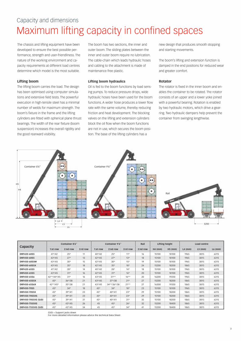
Maximum lifting capacity in confined spacesThe chassis and lifting equipment have been
developed to ensure the best possible per-
formance, strength and user-friendliness. The
nature of the working environment and ca-
pacity requirements at different load centres
determine which model is the most suitable.
lifting boom
The lifting boom carries the load. The design
has been optimised using computer simula-
tions and extensive field tests. The powerful
execution in high-tensile steel has a minimal
number of welds for maximum strength. The
boom’s fixture in the frame and the lifting
cylinders are fitted with spherical plane thrust
bearings. The width of the rear fixture (boom
suspension) increases the overall rigidity and
the good rearward visibility.
The boom has two sections, the inner and
outer boom. The sliding plates between the
inner and outer boom require no lubrication.
The cable-chain which leads hydraulic hoses
and cabling to the attachment is made of
maintenance-free plastic.
lifting boom hydraulics
Oil is fed to the boom functions by load sens-
ing pumps. To reduce pressure drops, wide
hydraulic hoses have been used for the boom
functions. A wider hose produces a lower flow
rate with the same volume, thereby reducing
friction and heat development. The blocking
valves on the lifting and extension cylinders
block the oil flow when the boom functions
are not in use, which secures the boom posi-
tion. The base of the lifting cylinders has a
new design that produces smooth stopping
and starting movements.
The boom’s lifting and extension function is
damped in the end positions for reduced wear
and greater comfort.
rotator
The rotator is fixed in the inner boom and en-
ables the container to be rotated. The rotator
consists of an upper and a lower yoke joined
with a powerful bearing. Rotation is enabled
by two hydraulic motors, which drive a gear-
ring. Two hydraulic dampers help prevent the
container from swinging lengthwise.
capacitycontainer 8’6’’ container 9’6’’ rail lifting height load centre
1:st row 2:nd row 3:rd row 1:st row 2:nd row 3:rd row 2:nd row h4 (mm) h5 (mm) l4 (mm) l5 (mm) l6 (mm)
(SJD) = Support jacks down For more detailed information please advice the technical Data Sheet
Container 8’6’’ Container 9’6’’
Rail
H5
H4
L4L5
L65200
Drf420-60S5 41*/42 25* 11 40*/42 25* 11* 16 15100 18100 1965 3815 6315
Drf450-60S5 43*/45 27* 13 42*/45 27* 13* 18 15100 18100 1965 3815 6315
Drf450-60S5m 43*/45 30* 15 42*/45 30* 15* 19 15100 18100 1965 3815 6315
Drf450-60S5X 43*/45 35* 18 42*/45 35* 18* 24 15200 18200 1865 3815 6315
Drf420-65S5 41*/42 28* 14 40*/42 28* 14* 18 15100 18100 1965 3815 6315
Drf450-65S5 43*/45 31* 16 42*/45 31* 16* 20 15100 18100 1965 3815 6315
Drf450-65S6 42**/44*/45 31* 16 43*/45 31** 16** 20 16200 19250 1965 3815 6315
Drf450-65S5X 45* 36*/38 21 43*/45 37*/38 21* 27 15200 18200 1865 3815 6315
Drf450-65S6X 42**/45* 35*/38 21 43*/45 34**/36*/38 21** 27 16300 19350 1865 3815 6315
Drf450-70S5 45* 34* 18 45* 34* 18* 23 15100 18100 1965 3815 6315
Drf450-70S5X 45* 39*/41 23 45* 40*/41 23* 29 15100 18200 1865 3815 6315
Drf450-70S5XS 45* 39*/41 23 45* 40*/41 23* 29 15100 18200 1865 3815 6315
Drf450-70S5XS (SJD) 45* 39*/41 31 45* 40*/41 31* 35 15100 18200 1865 3815 6315
Drf450-75S5XS 45* 43*/45 26 45 45* 26* 32 15200 18400 1865 3815 6315
Drf450-75S5XS (SJD) 45* 43*/45 34 45 45* 34* 41 15200 18400 1865 3815 6315

4
attachment
The primary function of the attachment is to
firmly attach the container during lifting. This
is done with four twistlocks which rotate,
thereby securely gripping the container’s
corner fittings.
The mechanical levelling ensures that the
twistlocks reach the corners, even if the con-
tainer is leaning.
The attachment can easily be adapted to dif-
ferent container standards. A hydraulic motor
drives the function via chains. The container
can also be moved sideways to facilitate
loading and unloading, or to compensate for
unbalanced loads. Two hydraulic cylinders
perform the side-shift movement.
attachment and rotator hydraulics
The functions are fed with a constant pres-
sure, which means there is no pumping of hy-
draulic oil when the functions are not in use.
One valve serves all the hydraulic functions in
the attachment. The valve ensures that each
hydraulic function is fed the exact amount of
oil needed to optimise the speed of the func-
tions’ movements. The attachment functions
are damped in the end positions.
chassis
The frame forms the basis of the machine’s
lifting and manoeuvring characteristics. The
frame’s beam construction, along with its
width, makes the reachstacker stable, torsion
resistant and service-friendly.
Firstly, a large number of computer simula-
tions have been run in order to eliminate
critical tensions under various kinds of strain.
The simulations were characterised by un-
compromising demands on the fundamental
principles of stability, manoeuvrability and
visibility. Secondly, the machine has then un-
dergone extensive field-testing to fully ensure
its dynamic strength.
The reachstacker is available with a variety
of wheelbases to fulfil demands on lifting
capacity in relation to manoeuvrability and
operating economy in the best way.
increased capacity
In some cases, high capacity requirements in
the second and third rows of containers, or on
the far rail track, call for the benefit of support
legs. In other cases, it may be the restricted
handling space that determines the most
suitable model.
Dimensionsaisle width (mm) turning radius (mm) main dimesions (mm) Service
weight (kg)a1 - 20 ft a2 - 40 ft r1 - 20 ft r3 - 40 ft clearance Wheels
100
100R3
R1
A1A2
B
V
H3
L
B V l h3
Drf420-60S5 11200 13600 8100 9400 4150 6055-12185 11200 4500 250 18.00x25/36 65500
Drf450-60S5 11200 13600 8100 9400 4150 6055-12185 11200 4500 250 18.00x25/40 67400
Drf450-60S5m 11200 13600 8100 9400 4150 6055-12185 11200 4500 250 18.00x25/40 69400
Drf450-60S5X 11200 13600 8100 9400 4150 6055-12185 11200 4600 300 18.00x33/36 77400
Drf420-65S5 11600 13600 8500 9400 4150 6055-12185 11700 4500 250 18.00x25/36 66500
Drf450-65S5 11600 13600 8500 9400 4150 6055-12185 11700 4500 250 18.00x25/40 69000
Drf450-65S6 11900 13900 8500 9450 4150 6055-12185 12000 4500 250 18.00x25/40 69800
Drf450-65S5X 11600 13600 8500 9400 4150 6055-12185 11700 4600 300 18.00x33/36 76300
Drf450-65S6X 11900 13900 8500 9450 4150 6055-12185 12000 4600 300 18.00x33/36 77500
Drf450-70S5 12000 13600 8900 9400 4150 6055-12185 12200 4500 250 18.00x25/40 69400
Drf450-70S5X 12100 13600 9000 9400 4150 6055-12185 12200 4700 300 18.00x33/36 77800
Drf450-70S5XS 12100 13600 9000 9400 4150 6055-12185 12200 4700 300 18.00x33/36 79300
Drf450-75S5XS 12500 13600 9400 9400 4150 6055-12185 12700 4750 300 18.00x33/36 82100
5
Ergonomics
No machine is better than its driverThe goal when developing the cabin has been
to assure the driver the best conceivable
safety, ergonomics and visibility.
Sound and vibration
The cabin is separately suspended and
isolated from the frame with powerful rubber
dampers. Effective shock absorption minimis-
es vibration. The cabin is fitted with insulation
material both inside and out. The maximum
noise level inside the cabin is 72 dB (A)
measured according to EN12053.
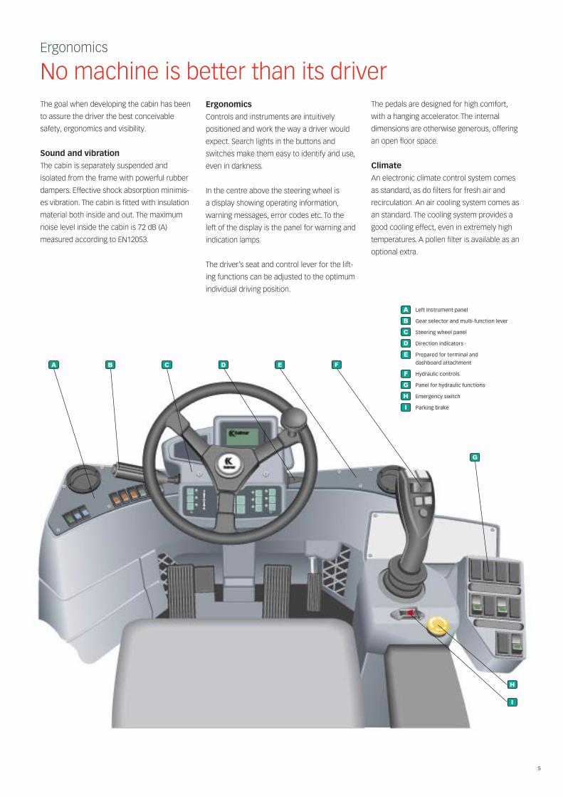
ergonomics
Controls and instruments are intuitively
positioned and work the way a driver would
expect. Search lights in the buttons and
switches make them easy to identify and use,
even in darkness.
In the centre above the steering wheel is
a display showing operating information,
warning messages, error codes etc. To the
left of the display is the panel for warning and
indication lamps.
The driver’s seat and control lever for the lift-
ing functions can be adjusted to the optimum
individual driving position.
The pedals are designed for high comfort,
with a hanging accelerator. The internal
dimensions are otherwise generous, offering
an open floor space.
climate
An electronic climate control system comes
as standard, as do filters for fresh air and
recirculation. An air cooling system comes as
an standard. The cooling system provides a
good cooling effect, even in extremely high
temperatures. A pollen filter is available as an
optional extra.
A
B
C
D
E
F
G
H
I
Left instrument panel
Gear selector and multi-function lever
Steering wheel panel
Direction indicators
Prepared for terminal and
dashboard attachment
Hydraulic controls
Panel for hydraulic functions
Emergency switch
Parking brake
A
B
C
D
E
F
G
H
I
A
B
C
D
E
F
G
H
I
A
B
C
D
E
F
G
H
I
A
B
C
D
E
F
G
H
I
A
B
C
D
E
F
G
H
I
A
B
C
D
E
F
G
H
I
A
B
C
D
E
F
G
H
I
A
B
C
D
E
F
G
H
I
A
B
C
D
E
F
G
H
I
A
B
C
D
E
F
G
H
I
A
B
C
D
E
F
G
H
I
A
B
C
D
E
F
G
H
I
A
B
C
D
E
F
G
H
I
A
B
C
D
E
F
G
H
I
A
B
C
D
E
F
G
H
I
A
B
C
D
E
F
G
H
I
A
B
C
D
E
F
G
H
I

6
Operational Performance
Performance is the result of how well the machines’s functions work together
The efficacy of the lifting equipment is
determined by a combination of lifting speed,
capacity, visibility and user-friendliness. Lifting
places heavy demands on the engine and
working hydraulics, but lifting is only part of
the operating cycle. Before the machine is in
position to load or unload, the demands are
instead on precise control with tight turn-
ing radius, effective brakes and high pulling
power. And of course, all the functions must
still perform optimally even after heavy use.
transmission
The transmission transfers power from the
engine to the hydraulic pumps and drive line.
The engine and gearbox control systems
work together to find the optimum balance
between power and fuel economy at any
given point.
The transmission system consists of a torque
converter and a gearbox. The same gearbox
is used whichever engine is chosen. The
gearbox is automatic, but can partly be shifted
manually. The torque converter is a hydraulic
coupling positioned between the engine and
gearbox. The gearbox and torque converter
work together via a joint hydraulic system.
Brakes
The brake circuit is separated from the
hydraulic system and has its own tank,
cooler and high-pressure filter. A temperature
transmitter in the separate tank regulates the
cooler fan.
The foot-brake valve, which controls the oil
feed to the brakes, is sensitive enough so that
the driver can brake optimally yet still gently.
The parking brake is activated automatically
when the ignition is turned off.
Drive line
The propeller shaft and drive axle transfer the
power from the transmission to the driving
wheels. The mountings on the propeller shaft
are fitted with cross-flanges for optimum
strength.
The drive axle shifts gear down in two stages,
differential and hub reduction. The engine
only achieves maximum torque at the drive
wheels, which spares the transmission.
Drive train Standard* optional
Engine Manufacturer Model
Volvo TAD 1250VE withair cooled intercooler
Cummins QSM11 withair cooled intercooler
Power 247 kW at 1900 rpm 261 kW at 2000 rpm
Peak torque 1760 Nm at 1400 rpm 1830 Nm at 1100-1400 rpm
Transmission
Driving axle
* Stage 2 and Tier 2 outside US and EU
Standarddrive train
Dana – 15.7TE32418 Dana – 15.7TE32418
Kalmar WDB Kalmar WDB
7
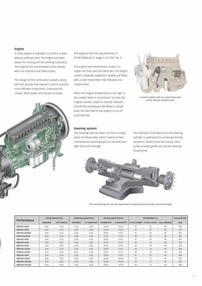
Cummins QSM11 with air cooled intercooler can be fitted as optional extra.
The new steering axle has few maintenance-requiring parts and high strucural strength.
engine
A Volvo engine is standard. Cummins is avail-
able as optional extra. The engine provides
power for driving and the working hydraulics.
The engines are low-emission turbo diesels
with unit injectors and intercoolers.
The design of the combustion vessels, along
with the precise fuel injection control, ensures
more efficient combustion. Emissions de-
crease, while power and torque increase.
The engines fulfil the requirements of
97/68*2004/26 EC stage 3, US EPA Tier 3.
The engine and transmission cooler is a
single unit that uses the same fan. The engine
cooler’s separate expansion vessels are fitted
with a level transmitter that indicates low
coolant level.
When the engine temperature is too high or
the coolant level or oil pressure too low, the
engine’s power output is actively reduced.
Should the oil pressure fall below a certain
level, the fuel feed to the engine is cut off
automatically.
Steering system
The steering axle has been cut from a single
piece of robust steel, which means as few
maintenance-requiring parts as possible and
high structural strength.
The hydraulics that feed oil to the steering
cylinder is optimised for enhanced driving
sensation. Orbitrol and the priority valve
jointly provide gentle yet precise steering
movements.
Performancelifting speed (m/s) lowering speed (m/s) Driving speed (km/h) Gradeability (%) Draw pull (kn)
unloaded at 70% of rated load unloaded at rated load unloaded (f/r) at rated load (f/r) at 2 km/h, unloaded at 2 km/h, at rated load max, unloaded max
Drf420-60S5 0,42 0,25 0,36 0,36 25/25 21/21 37 22 40 370
Drf450-60S5 0,42 0,25 0,36 0,36 25/25 21/21 37 22 40 370
Drf450-60S5m 0,42 0,25 0,36 0,36 25/25 21/21 37 22 40 370
Drf450-60S5X 0,42 0,25 0,36 0,36 27/27 21/21 28 18 40 320
Drf420-65S5 0,42 0,25 0,36 0,36 25/25 21/21 37 22 40 370
Drf450-65S5 0,42 0,25 0,36 0,36 25/25 21/21 37 22 40 370
Drf450-65S6 0,42 0,25 0,36 0,36 25/25 21/21 37 22 40 370
Drf450-65S5X 0,42 0,25 0,36 0,36 27/27 21/21 28 18 40 320
Drf450-65S6X 0,42 0,25 0,36 0,36 27/27 21/21 28 18 40 320
Drf450-70S5 0,42 0,25 0,36 0,36 25/25 21/21 37 22 40 370
Drf450-70S5X 0,42 0,25 0,35 0,35 26/26 20/20 27 17 39 320
Drf450-70S5XS 0,42 0,25 0,35 0,35 26/26 20/20 27 17 39 320
Drf450-75S5XS 0,42 0,25 0,35 0,35 25/25 19/19 25 15 35 320
8
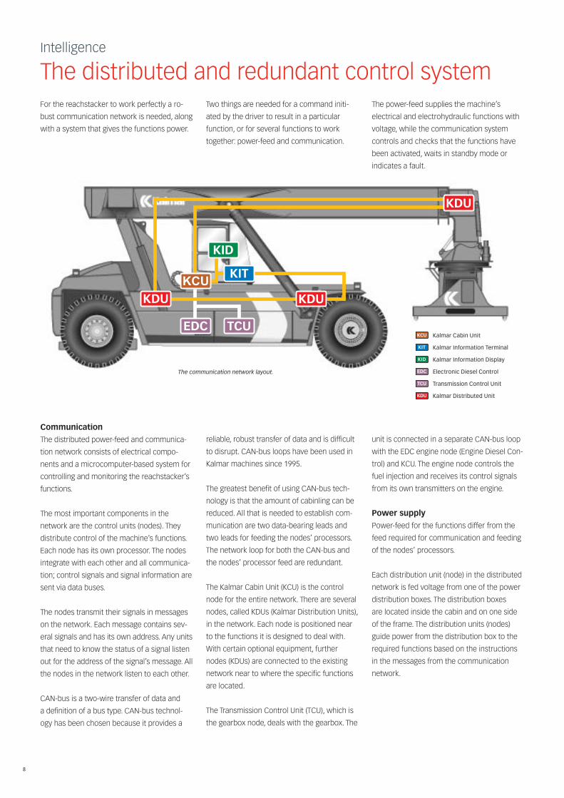
Intelligence
The distributed and redundant control systemFor the reachstacker to work perfectly a ro-
bust communication network is needed, along
with a system that gives the functions power.
Two things are needed for a command initi-
ated by the driver to result in a particular
function, or for several functions to work
together: power-feed and communication.
The power-feed supplies the machine’s
electrical and electrohydraulic functions with
voltage, while the communication system
controls and checks that the functions have
been activated, waits in standby mode or
indicates a fault.
The communication network layout.
Kalmar Cabin Unit
Kalmar Information Terminal
Kalmar Information Display
Electronic Diesel Control
Transmission Control Unit
Kalmar Distributed Unit
communication
The distributed power-feed and communica-
tion network consists of electrical compo-
nents and a microcomputer-based system for
controlling and monitoring the reachstacker’s
functions.
The most important components in the
network are the control units (nodes). They
distribute control of the machine’s functions.
Each node has its own processor. The nodes
integrate with each other and all communica-
tion; control signals and signal information are
sent via data buses.
The nodes transmit their signals in messages
on the network. Each message contains sev-
eral signals and has its own address. Any units
that need to know the status of a signal listen
out for the address of the signal’s message. All
the nodes in the network listen to each other.
CAN-bus is a two-wire transfer of data and
a definition of a bus type. CAN-bus technol-
ogy has been chosen because it provides a
reliable, robust transfer of data and is difficult
to disrupt. CAN-bus loops have been used in
Kalmar machines since 1995.
The greatest benefit of using CAN-bus tech-
nology is that the amount of cabinling can be
reduced. All that is needed to establish com-
munication are two data-bearing leads and
two leads for feeding the nodes’ processors.
The network loop for both the CAN-bus and
the nodes’ processor feed are redundant.
The Kalmar Cabin Unit (KCU) is the control
node for the entire network. There are several
nodes, called KDUs (Kalmar Distribution Units),
in the network. Each node is positioned near
to the functions it is designed to deal with.
With certain optional equipment, further
nodes (KDUs) are connected to the existing
network near to where the specific functions
are located.
The Transmission Control Unit (TCU), which is
the gearbox node, deals with the gearbox. The
unit is connected in a separate CAN-bus loop
with the EDC engine node (Engine Diesel Con-
trol) and KCU. The engine node controls the
fuel injection and receives its control signals
from its own transmitters on the engine.
Power supply
Power-feed for the functions differ from the
feed required for communication and feeding
of the nodes’ processors.
Each distribution unit (node) in the distributed
network is fed voltage from one of the power
distribution boxes. The distribution boxes
are located inside the cabin and on one side
of the frame. The distribution units (nodes)
guide power from the distribution box to the
required functions based on the instructions
in the messages from the communication
network.
KDU
KDU KDU
KIT
KID
EDC TCU
KCU

9
control functions
The driver and machine communicate via the
Kalmar Information Terminal (KIT) and the Ka-
lmar Information Display (KID). Control signals
initiated by the driver are transferred to the
KCU, which handles all incoming signals from
the controls in the cabin, and sends messages
out into the communication network.
The system also distributes information to the
driver such as alarm warnings, operating de-
tails and action-guided information. In these
cases, messages are sent from one of the
nodes in the network, captured by the KCU,
and then presented in the KID or the panel for
warning and indication lamps. The KID shows
information from the control units in the form
of messages, status, fault indication etc.
ReliabilityHigh reliability is achieved by reducing the
number of components and ensuring each
individual component maintains a consistent
high quality.
One of our guiding principles in designing the
reachstacker was to minimise the number
of potential sources of error. Therefore, the
machine consists of as few components and
moving parts as possible. The functionality
and operational reliability of each component
is assured by extensive testing.
the machine’s structure
The Kalmar reachstacker has been available
on the market since the mid-1980s. There are
a lot of Kalmar machines around the world,
used in all kinds of climates. Overall, this has
helped build our completely unique experi-
ence of this machine type. The machine’s
lifting equipment, frame and structure has
been fine-tuned over the years, and today we
can offer the best balance of performance
and operational reliability in the machine’s
mechanical components and structure.
hydraulic components and couplings
The number of hydraulic components and
hydraulic couplings has been minimised. The
main valve has an integrated servo, which
helps increase control of the oil flow and keep
the number of components to a minimum.
The boom’s lifting and extension cylinders
are fitted with double gaskets. Moreover, the
machine is fitted with extremely reliable, well-
sealed ORFS (O-Ring Face Seal) couplings in all
the hydraulic hoses as standard.
temperature control
and hydraulic cleanliness
In order to maintain optimum functionality
in the hydraulic system even under extreme
operating conditions, cleaning and cooling
of the hydraulic oil is highly efficient. The
brake circuit is separated from the rest of the
hydraulic system and is fitted with its own
cleaning process and cooling system.
Redundant communication network
A network of distributed control units (nodes)
using limited cabling and fewer couplings,
meaning fewer sources of error.
The power-feed for each node is independent
of the other nodes, which help prevent other
nodes from being disrupted, should one stop
working. The same applies to the transfer
of control signals. Both the power-feed and
control signal transfer are redundant, so that
power or signals always have two paths to
choose for maintaining communication, thus
offering extra safety and reliability.
Keyboard (KIT)
Warning and indication lamps (KIT)
Display (KID)
Alarm indicator
10
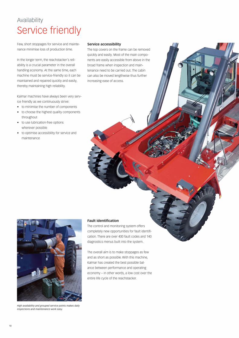
Availability
Service friendlyFew, short stoppages for service and mainte-
nance minimise loss of production time.
In the longer term, the reachstacker´s reli-
ability is a crucial parameter in the overall
handling economy. At the same time, each
machine must be service-friendly so it can be
maintained and repaired quickly and easily,
thereby maintaining high reliability.
Kalmar machines have always been very serv-
ice friendly as we continuously strive:
• tominimisethenumberofcomponents
• tochoosethehighestqualitycomponents
throughout
• touselubrication-freeoptions
wherever possible
• tooptimiseaccessibilityforserviceand
maintenance
Service accessibility
The top covers on the frame can be removed
quickly and easily. Most of the main compo-
nents are easily accessible from above in the
broad frame when inspection and main-
tenance need to be carried out. The cabin
can also be moved lengthwise thus further
increasing ease of access.
fault identification
The control and monitoring system offers
completely new opportunities for fault identifi-
cation. There are over 400 fault codes and 140
diagnostics menus built into the system.
The overall aim is to make stoppages as few
and as short as possible. With this machine,
Kalmar has created the best possible bal-
ance between performance and operating
economy – in other words, a low cost over the
entire life cycle of the reachstacker.
High availability and grouped service points makes daily inspections and maintenance work easy.

11
Cargotec improves the efficiency of cargo flows by offering solutions for
the loading and unloading of goods on land and at sea – wherever cargo
is on the move. Cargotec’s main daughter brands for cargo handling
Hiab, Kalmar and MacGregor are global market leaders in their fields.
Cargotec’s global network offers extensive services that ensure the
continuous, reliable and sustainable performance of equipment.
cargotec Sweden aBTorggatan 3
SE-340 10, Lidhult, Sweden tel. +46 372 260 00 fax +46 372 263 90
www.cargotec.com
9215
24-0
711/
0911
15 K
ST R
åd &
Res
ulta
tW
e re
serv
e th
e rig
ht to
cha
nge
the
desi
gn a
nd te
chni
cal d
ata
with
out p
rior
not
ice.
Tol
eran
ces
acco
rdin
g to
K-s
tand
ard
9543
0.00
08/0
009


