22

CONTENT 1. Forewords 2 1.1. History 2 1.2. Leeb Hardness Test (definition) 2 2. Features and Applications 3 2.1. Introduction 3 2.2. Specifications 3 2.3. Applications 3 3. Layout and Key-pad Description 4 3.1. Layout of HARTIP 2000 4 3.2. Function of Key 5 3.3. Special Features of Impact Devices 5 4. Symbols and Illustrations 5 4.1. Symbols and Illustrations 5 4.2. Measurement and Conversion Table 6 S. Preparation before Measuring 7 5.1. Requirements for the sample 7 5.2. Requirements for the weight of the sample 7 5.3. Requirement for the surface hardened layer of the sample 8 5.4. Surface of the test sample should not be magnetic. 8 5.5. For test sample of curving surface 8 5.6. Supporting the Samples during Testing 8 5.7. Samples with Curved Surfaces 9 6. Operation 10 6.1. Switch on the tester 10 6.2. Parameter Setup 10 6.3. Operation 14 6.4. Data storing and re-reading 15 6.5. Statics 16 6.6. Print-Out 16 6.7. Calibration 17 6.8. Restore factory settings and check serial no. 18 7. Maintenance and Repair 19 7.1. Maintenance of the Impact Device 19 8. Optional Accessories 20
1

1. Forewords
1.1. History
The Leeb measuring method was first brought into measurement technology in 1978. It is defined as the quotient of an impact body's rebound velocity over its impact velocity, multiplied by 1000. Harder materials produce a higher rebound velocity than softer materials. For a specific group of material (e.g. steel, aluminum. etc.), Leeb hardness value represents a direct relationship to its hardness properties. For ordinary metal, conversion curves of hardness HL versus other standard static hardness (HB, HV, HRC, etc.) are available, enabling you to convert HL into other hardness values.
1.2. Leeb Hardness Test (definition)
An impact body with a spherical test tip made of tungsten carbide is propelled against the sample surface by a spring force and then rebounds back At a distance of 1mm from the sample surface, the impact and rebound velocity of the impact body are measured by the following method: A permanent magnet embedded in the impact body, when passing through the coil in its coil holder, induces in the coil an electric voltage proportional to the velocities of the magnet. Leeb hardness is expressed by the following formula:
HL= r *1000
Where: HL is Leeb Hardness V, is the rebound velocity of the impact body V is the impact velocity of the impact body The voltage characteristic of output signal, when the impact body passes through the induction coil is illustrated in the following figure:
.,...,000=y,. 1000 A V!
Time
8—v,
Impact phase Rebound phase --4>
Voltage characteristic of output signal
A Leeb's Hardness Tester measures the hardness of sample material in terms of Hardness Leeb (HL), which can be converted into other Hardness units (Rockwell B and C, Vicker, Brinell and Shore D).
2
A—V,

2. Features and Applications
2.1. Introduction
HARTIP 2000 is an innovative portable Leeb hardness tester with our new patent technology which makes HARTIP 2000 a universal impact direction hardness tester. It is no need to set up impact direction when taking measurement by any angle. Therefore, HARTIP 2000 offers a linear accuracy comparing to the angle compensating method. HARTIP 2000 is also a cost saving hardness tester and has many other features.
2.2. Specifications
Principle Accuracy Display Impact device Impact direction Hardness scale Measuring range
Materials Memory Statistics
Recalibration Indicator Communication interface
Auto power off Power supply Working environment
Dimension (mm) Net weight (g) Standard
Leeb hardness measurement .±0.3% @ HL=800, Repeatability: ±2HL Digital LCD with backlight DU (External) /DL, D+15, G, C(External, optional) Universal angle type HL/HRC/HRB/HB/HV/HS/ab HL170-960/HRC17-69/HRI313-109/HB20-655/HV80-940/ HS32-99.5 11 common metal materials 100 data can be stored and re-readable Calculated automatically
Allowed by user Low battery RS232 to micro-printer, Bluetooth (optional) to Bluetooth micro-printer Auto 1.5V AA alkaline battery x 2 -10°C -+45°C 124x67x30 240
Gonforming to ASTM A956
2.3. Applications
Hardness tests on installed machines or steel structures: e.g. on heavy and large work-piece or on permanently installed system parts. Rapid testing of multiple measuring areas for examination of hardness variations over larger regions. Measuring hardness for produced parts at production line. Identifying metallic material stored in a warehouse. Ineffectiveness analysis of permanent parts, pressure -vessel, turbo generator.
3
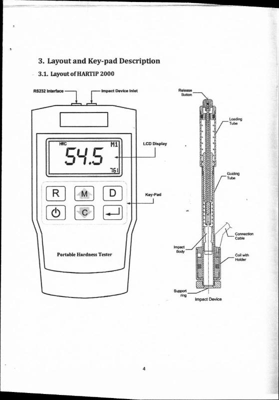
RS232 Interface Impact Device Inlet
Mi
• • 16
LCD Display
Connection Cable
Coil with Holder
Portable Hardness Tester
Key-Pad R M D
3. Layout and Key-pad Description
3.1. Layout of HARTIP 2000
4

3.2. Function of Key
R Read the memory
Power On Power Off
: Change parameter Decrease the value Turn the page back
: Confirm the setup View the statics values
[ ft" : Menu
Increase the value Turn the page forth Delete the current reading Delete the stored values
D
3.3. Special Features of Impact Devices
Type Brief description D Universal standard unit for majority of hardness testing
assignments. D+15 Slim front section
Application: 1 - grooves and recessed surfaces. DL Extremely slim front section
Application:
.,
- extremely confined spaces - base of grooves
C Reduced impact energy ( compared with type D). Application: - surface hardened components, coatings
- minimum layer thickness: 0.2mm. - thin walled or impact sensitive components (small measuring indentation).
G Increased impact energy(approx. 9 times that of type D) Application: - Brinell hardness range only
- heavy cast and forged parts with lower demands on surface finish.
4. Symbols and Illustrations
4.1. Symbols and Illustrations
Symbol Meaning LD Leeb hardness value obtained with impact device D LG Leeb hardness value obtained with impact device G LC Leeb hardness value obtained with impact device C LD +15 Leeb hardness value obtained with impact device 0+15 LDL Leeb hardness value obtained with impact device DL HLD Leeb hardness value used with impact device D HB Brinell hardness value HRB Rockwell B hardness value HRC Rockwell C hardness value HS Shore hardness value HV Vicker hardness value ab (N/mm2) Strength value
5

4.2. Measurement and Conversion Table
Ranee for measurement and conversion; IMPACT DEVICE D HLD: 170-960
HRC HRB HB HV HS ab (N/inm2 ) Steel & cast steel 20.0-67.9 59.6-99.5 80-647 80-940 32.5-99.5 375-1710 Cold work tool steel 20.5-67.1 80-898 1170-2639 Stainless steel & High-temp. resistant steel
19.6-62.4 46.5-101.7 85-655 85-802 740-1725
Cast iron with lamellar graphite (GG)
93-334
Cast iron with nodular graphite (GGG)
131-387
Cast aluminum alloys
23-85 30-159 80-195
Copper-zinc alloys (Brass)
13.5-95.3 40-173
Copper-aluminum / Copper-tin alloys (Bronze)
14-100 60-290
Wrought copper alloys
14-100 45-315
Forging steel 142-651 Rolling steel 140-651
IMPACT DEVICE DL LDL: 560-950 HRC HRB HB HV HSD
STEEL 20.6-68.2 37.0-99.9 81-646 80-950 30.6-96.8
IMPACT DEVICE D+15 LD+1S: 300-900 HRC HRB HB HV HSD
STEEL 19.3-67.9 80-638 80-937 33.3-99.3 CW. ST 19.8-68.2 80-935
IMPACT DEVICE G L G: 300-750 HRC HRB HB HV HSD
STEEL 47.7-99.9 90-646 GC.IRON 92-326 NC.IRON 127-364
IMPACT DEVICE C L C: 350-950 HR C HRB H B HV HSD
STEEL 20.0-69.5 80-683 80-996 31.9-102. 3
CW. ST 20.7-68.2 100-94 1
6

5. Preparation before Measuring
5.1. Requirements for the sample
5.1.1. The surface temperature of sample should be less than 120 °C.
5.1.2. The samples must feature a metallic smooth, ground surface, in order to eliminate erroneous measurements brought about by coarse grinding or lathe scoring. Roughness of the finished surface should not exceed values shown in following table:
Types of impact devices Max surface roughness of sample Ra D/D+15/DL G C
2gm 7gm 0.4gm
5.2. Requirements for the weight of the sample For samples weighing over 5 kg and of compact shape, no support is needed. Samples weighing between 2-5 kg, and also for heavier samples with protruding parts or thin walls, should be placed on a solid support in such a manner that they do not bend or move by the impact force. Samples weighing less than 2 kg should be firmly coupled with a stable support weighing over 5 kg.
For coupling purposes, The coupling surface between the sample and base plate should be flat, plane parallel and ground. A thin proper layer of coupling paste is to be applied to the contact surface of the sample. The sample should be firmly pressed against the surface of the base plate by moving it with a circular motion. The direction of impact should be perpendicular to the coupling surface.
For the coupling operation, the following prerequisites must be fulfilled: The contact surface of the sample and the surface of the base plate must be flat, plane parallel and ground. The direction of the test impact must be perpendicular to the coupled surface. Minimum thickness of the sample for coupling under various impact devices are shown in following table:
Types of impact devices Minimum thickness D/D+15/DL 3mm G 10mm C 1mm
Proper Coupling: Proper coupling requires a little experience. Insufficiently coupled samples produce large variations of individual measurements, L-values which are too low and the operation is characterized by a rattling noise upon impact of the test tip.
7
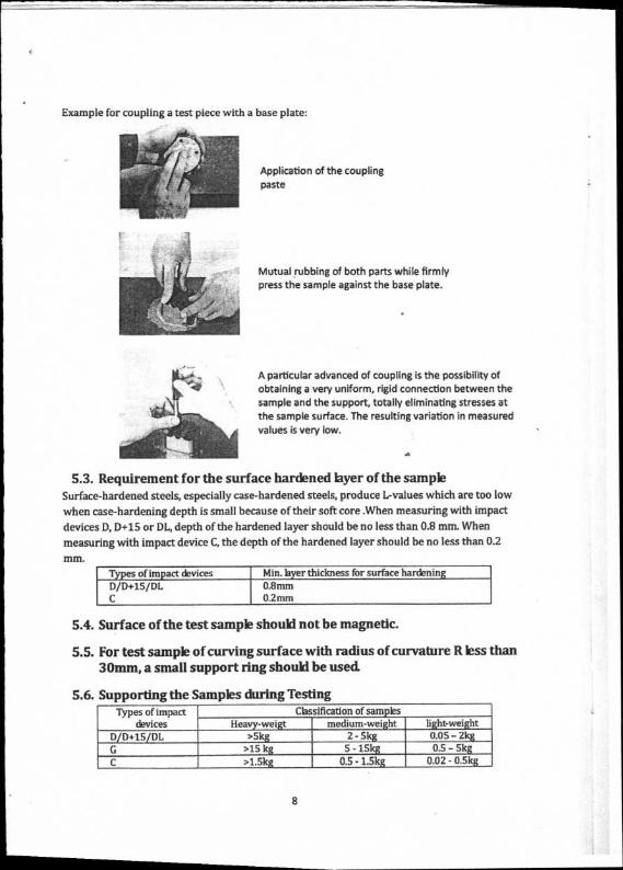
Example for coupling a test piece with a base plate:
Application of the coupling paste
Mutual rubbing of both parts while firmly press the sample against the base plate.
A particular advanced of coupling is the possibility of obtaining a very uniform, rigid connection between the sample and the support, totally eliminating stresses at the sample surface. The resulting variation in measured values is very low.
5.3. Requirement for the surface hardened layer of the sample Surface-hardened steels, especially case-hardened steels, produce L-values which are too low
when case-hardening depth is small because of their soft core .When measuring with impact
devices D, D+15 or DL, depth of the hardened layer should be no less than 0.8 mm. When
measuring with impact device C, the depth of the hardened layer should be no less than 0.2
MM.
Types of impact devices Min. layer thickness for surface hardening D/D+15/DL C
0.8mm 0.2mm
5.4. Surface of the test sample should not be magnetic.
5.5. For test sample of curving surface with radius of curvature R less than 30mm, a small support ring should be used
5.6. Supporting the Samples during Testing Types of impact
devices Classification of samples
Heavy-weigt medium-weight light-weight D/D+15/DL >5kg 2 - 5kg 0.05 - 2kg G >15 kg 5 - 15kg 0.5 - 5kg C >1.5kg 0.5 - 1.5kg 0.02 - 0.5kg
8
When measuring hardness with HARTIP 3000, the following has to be noticed: Despite the low
mass of the impact body and low impact energy, a relatively large impact force within short
duration is generated when the impact body hits the measuring surface.
Types of impact devices 0/0+15/DL G C
Max. impact force 900N 2500N 500N
No particular precautions are necessary for heavy-weight samples with compact shape.
Smaller and lighter samples or workpieces may yield or flex under this force, producing
too-low L-values with excessively large variation. Even with big or heavy workpieces, it is
possible for thin-wall regions or thinner protruding parts to yield upon impact. Depending on
the frequency of the resilient yielding action, the measured L-value may be abnormally low or
high. Under many situation, potential problems can be checked in the following manner:
a) Medium-weight samples and also heavier samples with protruding parts or thin walls
should be placed on a solid support in such a manner that they do not move or flex during the
test impact.
b) Light-weight samples should be rigidly "coupled" with a non-yielding support such as a
heavy base plate. Clamping in a vice is of no value, since the samples become exposed to stress
and because complete rigidity is never attained. As a rule, the measured L-values would be too
small and show excessive variations.
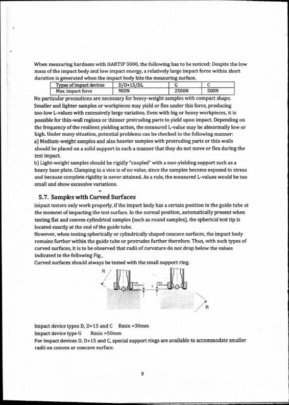
5.7. Samples with Curved Surfaces lthpact testers only work properly, if the impact body has a certain position in the guide tube at
the moment of impacting the test surface. In the normal position, automatically present when
testing flat and convex-cylindrical samples (such as round samples), the spherical test tip is
located exactly at the end of the guide tube.
However, when testing spherically or cylindrically shaped concave surfaces, the impact body
remains further within the guide tube or protrudes further therefore. Thus, with such types of
curved surfaces, it is to be observed that radii of curvature do not drop below the values
indicated in the following Fig..
Curved surfaces should always be tested with the small support ring.
Impact device types D, D+15 and C Rmin .30mm
Impact device type G Rmin =50mm
For impact devices D, D-1-15 and C, special support rings are available to accommodate smaller
radii on convex or concave surface.
9

6. Operation
6.1. Switch on the tester
Press the key to switch on the tester and press the key t J again to switch off the
tester. When the tester is switched on, the tester will enter into measuring mode.
6.2. Parameter Setup
Press
Operation Diagram
M
Press CI Press C
M
Press
► ID DL D15 C I Press
PROB (Probe Setup)
Press C
C
M1 M2 M9 MO —O. M11 O. —P. MATE (Material Setup)
Press
Press CI
HS HV -41-1 C— °b -4F— -4—
HB
HLD HRCHRB CONV (Hardness Scale)
Press C
If• ►
Press C
0 3 —0- 4 —IP- 5 -0- AVER (Mean Time)
Press C Press C
SOFF (Storage)
SON(Storage On) SOFF(Storage Off) J
Press C
►
Press C
BLUE 4. ► (Bluetooth Print –
(RS232P232
Print On) (PriPOFF
nt Off) On, Optional)
Press C Presml — --0-
444, —Calibration —0-Press
POFF (Print Setup)
Press-4i CAL (Calibration) 3"
X -41-1 3" C
Pre s M
10
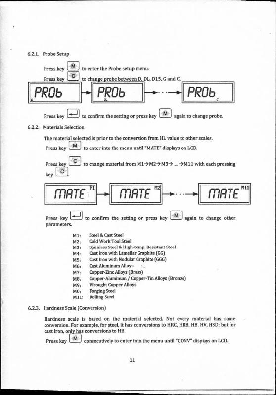
6.2.1. Probe Setup
Press key
Press key
• M
to enter the Probe setup menu.
to change probe between D, DL, D15, G and C.
0 PROb
a
PRUE),
Press key
to confirm the setting or press key 1 M 1 again to change probe.
6.2.2. Materials Selection
The material selected is prior to the conversion from HL value to other scales.
Press key M
to enter into the menu until "MATE" displays on LCD.
Press C
to change material from M1-42M3--> —>M11 with each pressing
key
marr Mii
S tillI
mi iuRiC
Tr
M2 rncti-r III ► I I
Press key parameters.
to confirm the setting or press key again to change other
M1: Steel & Cast Steel
M2: Cold Work Tool Steel
M3: Stainless Steel & High-temp. Resistant Steel
M4: Cast Iron with Lamellar Graphite (GG)
MS: Cast Iron with Nodular Graphite (GGG)
M6: Cast Aluminum Alloys
M7: Copper-Zinc Alloys (Brass)
M8: Copper-Aluminum / Copper-Tin Alloys (Bronze)
M9: Wrought Copper Alloys
MO: Forging Steel
M11: Rolling Steel
6.2.3. Hardness Scale (Conversion)
Hardness scale is based on the material selected. Not every material has same
conversion. For example, for steel, it has conversions to HRC, HRB, HB, HV, HSD; but for
cast iron, othias conversions to HB.
Press key consecutively to enter into the menu until "CONY" displays on LCD.
11

' tn
CONY tom OOP !V
AVER AVER
Press key to change hardness scale from HLDHRC—>HB—>HV---)HS-->ab
with each pressing key
Press key to confirm the setting or press key M again to go to next item of menu.
6.2.4. Mean Time
With HARTIP2000, the statics values can be calculated automatically after setup mean time.
Press key M consecutively to enter into menu until "AVER" displays on LCD.
Press key to select mean time from 0-33—)445 circularly by each pressing key C
AVER 5
Press to confirm the setting or press key again to go to next item of menu.
6.2.5. Storage
The HARTIP2000 has a memory capacity of 999 data. The stored values can be re-readable on LCD.
Press key consecutively to enter into menu until "SOFF" displays on LCD.
Press key C to change the setting between "SOFF" and "SON" alternatively.
SOFF Cf1 s ...1U1 IN
Press key to confirm the setting or press key again to go to next item of menu. When select "SON", a "S" appears on LCD which means the function of storage is activated
12

6.2.6. Printing Setup
Press key
Press key I
consecutively to enter into the menu until "POFF" displays on LCD.
to change the setting between "POFF", "bLUE" and "P232" alternatively.
PUFF bLUE CO I L.-IL
Press key to confirm the setting or press key l M again to go to first item of menu. When selecting "PON", an indicator "17- will appears on left side of LCD which means the communication function is activated for printing.
13

6.3. Operation
6.3.1. Take measurement
Switch on the tester, the instrument will go into measuring mode automatically. If the parameters are needed to change, please refer to 6.2.
6.32. Load spring force
Hold the impact device with left hand while push the loading tube with right hand toward to the end. Then loose the force and let the loading tube back to original position.
6.3.3. Release
14

EOF M RS
026 FILDb OF
MI RS
COI
ALE MI RS
WI
Place the impact device against the object to be measured. Then press the release button on top of the impact device with finger of right hand. The measuring value will display on LCD. Please note: During the measurement, the impact device must be placed vertically with a little force against the surface of workpiece. Otherwise, it may affect the accuracy.
6.4. Data storing and re-reading
6.4.1. Set the storage function of tester to be activated. Please refer to 6.2.5. A "S" displays on LCD. At this time, all measuring values will be stored automatically into the memory.
FLO Ms rtnr) out., 026
6.4.2. During the tester power on, press key R after "MEMR" displays and then the last stored value will display.
39.9 :6 mi.
6.4.3. Press key or to turn the page and view measuring values. When "EDF" or "b0F" displays with turning page, it reminds you it is at the end.
6.4.4. Clear the memory
Delete the stored data from memory.
Under the re-readable mode, press and hold the key
LCD. Then press key -.I-1 to confirm the deletion.
[ o ) until "dELE" displays on
15
EILD
• 7 / 86 R M
s
6.25
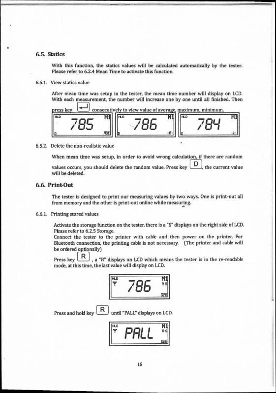
6.5. Statics
With this function, the statics values will be calculated automatically by the tester. Please refer to 6.2.4 Mean Time to activate this function.
6.5.1. View statics value
After mean time was setup in the tester, the mean time number will display on LCD. With each measurement, the number will increase one by one until all finished. Then
ress ke consecutively to view value of average maximum, minimum. FLO Mi
7 0 C / LI ,...1 .D RUE
11-D ... Ml
i 8 !.....
/ LI D -43-
M1
_ / 8q L._
6.5.2. Delete the non-realistic value
When mean time was setup, in order to avoid wrong calculation, if there are random
values occurs, you should delete the random value. Press key , the current value will be deleted.
6.6. Print-Out
The tester is designed to print our measuring values by two ways. One is print-out all from memory and the other is print-out online while measuring.
6.6.1. Printing stored values
Activate the storage function on the tester, there is a "S" displays on the right side of LCD. Please refer to 6.2.5 Storage. Connect the tester to the printer with cable and then power on the printer. For Bluetooth connection, the printing cable is not necessary. (The printer and cable will be ordered optionally)
Press key [ R , a "R" displays on LCD which means the tester is in the re-readable mode, at this time, the last value will display on LCD.
Press and hold key until "PALL" displays on LCD.
HLD Mi • ris-a R S
I ILL C26
16

M10 'C /" —1 LI c
to
HLD
a
Press key to print out all data.
6.6.2. Printing on line
Activate the communication on the tester, there is a "17" displayed on LCD. Please refer to 6.2.6 Printing Setup. Connect the tester to the printer with cable. Take measurements, all values will be printed out one by one with each measurement
6.7. Calibration
After long time of use, the ball tip on impact body may be worn out which would lead inaccuracy. In order to compensate such error, the tester is designed to re-calibrate by user.
Press key in turn to dis la "CAL" on the LCD.
Press and hold Key [---1 for 3 seconds to enter into the mode of calibration.
.W
l nrn M1a ULIU
.I7 d3
At the mode of calibration, you are asked to take 3 measurements(impact direction: downwarchle) on standard test block in total. Please follow up the direction indication on LCD to take measurements.
During the measurements, you can delete the unsatisfied reading by press key Also, by any time, at this mode, you can abandon the operation by letting the inswument shut down automatically after 3 minutes of no use.
After taking 3 measurements on test black, press key to display average value. At this time, the arrow disappears and an indicator "AVE" is displayed on the right bottom of LCD.
If the average value differs from the standard value of test block, you can press and hold
key for 3 seconds, "CALD" will flash once on the screen, and then an indicator
"ADJ" will display on the right bottom of the LCD, you can press key M or C
to increase or decrease the value on LCD until the value is same as the value of test block
17

Mi. 'n7On / LIU
ADJ
HLD
p
Press key to finish the calibration and turn back to normal measuring mode.
6.8. Restore factory settings and check serial no.
6.8.1. Restore factory settings
1. Press and hokl button while turning on the tester, "ESC" will display on the
LCD after release
2. Press consecutively, the "ESC" and "FSET" will display on the LCD in turn.
ESC
FSET 3. Press P1 key to restore factory settings when "FSET" displays on the LCD, and then the tester will return to the measuring mode.
6.82. Check serial no.
1. Press and hold button while turning on the testei, serial no. will display on the LCD.
2. Release and press the tester will return to the measuring mode.
18
7. Maintenance and Repair Do your best to avoid shock, heavy dust, damp, strong magnetic field, and oil stain.
7.1. Maintenance of the Impact Device
The devices do not require any particular care other than periodic cleaning of the impact body and the guide tube after performing approximately 1000-2000 tests. During cleaning, the following procedures need to be observed: Unscrew support ring and remove impact body from guide tube. Clean off any dirt and metallic dust from the impact body and the spherical test tip. Clean guide tube with the special brush provided. Do not apply oil to any parts for the impact device. Please make sure to keep the spring of impact device at releasing position, do not let the spring pressed by locking impact body after working and being storage.
19
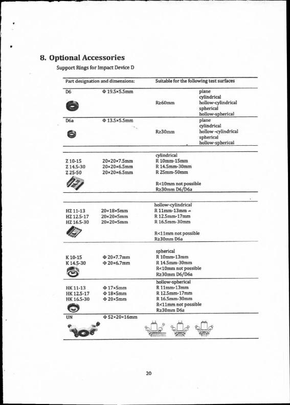
8. Optional Accessories Support Rings for Impact Device D
Part designation and dimensions: Suitable for the following test surfaces
D6 19.5x5.5mm plane cylindrical
1110 Ra6Onun hollow-cylindrical spherical hollow-spherical
D6a 4, 13.5x5.5mm plane cylindrical
e0 Ra3Omm hollow -cylindrical
spherical hollow-spherical
cylindrical Z 10-15 20 x 20 x 7.5mm R lOmm-15mm Z 14.5-30 20x20x6.5mm R 14.5mm-30mm Z 25-50 20x20x6.5mm R 25mm-50rom
R<10nun not possible R.?.30mm D6/D6a
hollow-cylindrical HZ 11-13 20.18x5mm R llmm-13mm HZ 12.5-17 20x20x5mm R 12.5mm-17mm HZ 16.5-30 20x 20x5mm R 16.5mm-30mm
R<11mm not possible Ra3Omm D6a
spherical K 10-15
20x7.7mm
R lOmm-13mm K 14.5-30
20x6.7mm
It 14.5mm-30mm R<10nun not possible Ra3Omm D6/D6a
HK 11-13 HK 12.5-17 HK 16.5-30
17x5mm 4, 18x5mm 4, 20x5mm
hollow-spherical R 11mm-13mm R 12.5mm-17mm R 16.5mm-30mm R<11mm not possible R.P..30mm D6a
UN 4) 52x20x16mm
20

Sino Age Development Technoloay No.18 Thong Goan Cun East Road M507
Haidian Beijing 100083, P. R. China TEL: +86 (10) 8260-0228, 5166-3600
FAX: +86 (10) 8260-0229 [email protected]
www.sadtcom.cn


