- 14 - English Characteristics of the operator 1 1.0 General characteristics ............................................................................................................................................................................. 15 1.1 Technical data ........................................................................................................................................................................................... 15 1.2 Choosing the type of automation .............................................................................................................................................................. 15 Checks and operations prior to the operator installation 3 3.0 Checking the gate ..................................................................................................................................................................................... 17 3.1 Checking the operator components .......................................................................................................................................................... 17 3.2 Mounting tools........................................................................................................................................................................................... 18 4 4.0 Positioning the mountings ......................................................................................................................................................................... 18 4.1 Prepping the rear operator mounting ........................................................................................................................................................ 19 4.1.1 Operator fixed on iron posts ...................................................................................................................................................................... 19 4.1.2 Operator fixed on wooden posts ............................................................................................................................................................... 19 4.1.3 Operator fixed on masonry posts .............................................................................................................................................................. 19 4.1.4 Rear operator mounting - special cases ................................................................................................................................................... 20 4.2 Fixing the rear operator mounting ............................................................................................................................................................. 21 4.3 Temporary installation of the operator ....................................................................................................................................................... 21 4.4 Positioning the front operator mounting .................................................................................................................................................... 22 4.5 Final installation of the operator ............................................................................................................................................................... 23 4.5.1 Mechanical fixing ...................................................................................................................................................................................... 23 4.5.2 Checking the motion ................................................................................................................................................................................. 23 4.5.3 Electrical connection ................................................................................................................................................................................. 23 4.5.4 Fitting the protection casing and removing the bleed screw .................................................................................................................... 23 4.5.5 Bleeding .................................................................................................................................................................................................... 24 Checks and adjustments 5 5.0 Checking and adjusting the thrust force .................................................................................................................................................... 24 7 7.0 Maintenance ............................................................................................................................................................................................. 25 7.1 Troubleshooting......................................................................................................................................................................................... 25 Installing the operator Notes for the installer Contents / Characteristics Description of the automation system 2 2.0 Components layout ................................................................................................................................................................................... 16 2.1 System electrical connection ................................................................................................................................................................... 16 Emergency manoeuvre 6 6.0 Emergency manoeuvre - use of the manual release .............................................................................................................................. 24
Transcript
- 14 -
En
glis
h
Characteristics of the operator11.0 General characteristics ............................................................................................................................................................................. 151.1 Technical data ........................................................................................................................................................................................... 151.2 Choosing the type of automation .............................................................................................................................................................. 15
Checks and operations prior to the operator installation33.0 Checking the gate ..................................................................................................................................................................................... 173.1 Checking the operator components .......................................................................................................................................................... 173.2 Mounting tools........................................................................................................................................................................................... 18
44.0 Positioning the mountings ......................................................................................................................................................................... 184.1 Prepping the rear operator mounting ........................................................................................................................................................ 194.1.1 Operator fi xed on iron posts...................................................................................................................................................................... 194.1.2 Operator fi xed on wooden posts ............................................................................................................................................................... 194.1.3 Operator fi xed on masonry posts.............................................................................................................................................................. 194.1.4 Rear operator mounting - special cases ................................................................................................................................................... 204.2 Fixing the rear operator mounting............................................................................................................................................................. 214.3 Temporary installation of the operator....................................................................................................................................................... 214.4 Positioning the front operator mounting .................................................................................................................................................... 224.5 Final installation of the operator ............................................................................................................................................................... 234.5.1 Mechanical fi xing ...................................................................................................................................................................................... 234.5.2 Checking the motion ................................................................................................................................................................................. 234.5.3 Electrical connection ................................................................................................................................................................................. 234.5.4 Fitting the protection casing and removing the bleed screw .................................................................................................................... 234.5.5 Bleeding .................................................................................................................................................................................................... 24
Checks and adjustments55.0 Checking and adjusting the thrust force.................................................................................................................................................... 24
Description of the automation system22.0 Components layout ................................................................................................................................................................................... 162.1 System electrical connection ................................................................................................................................................................... 16
Emergency manoeuvre 66.0 Emergency manoeuvre - use of the manual release .............................................................................................................................. 24
- 15 -
En
glis
h
1. CHARACTERISTICS OF THE OPERATOR1.0 GENERAL CHARACTERISTICS• ZT 4 is a hydraulic swing gate operator, specially designed for residential use.• The ZT 4 operator, if installed correctly, conforms to the current safety standards.List of versions:C: Hydraulic lock for closing only (with lock inaccessible when the gate is open)SF: No hydraulic lock - braking action (the gate leaf can be moved by hand with a minimum of resistance, if moved slowly; there is also a
release device to facilitate opening -needs an electric lock)• The C version, with hydraulic closing lock, does not require the use of the electric lock and keeps gate leaves of less than 1.8
m in closed position. • The emergency release (to be used in the event of a power failure) is safe to use and easily manoeuvrable and enables the user to move the
gate by hand using the triangular key provided. The release is easily accessible via a hatch on the upper cover of the operator.• Safety against entrapment risks is guaranteed by sensing valves, settable during installation.
1.1 TECHNICAL DATA
Warning!
The noise level of the above models, referred to the working of the operator, independently of the gate leaf and the post, falls within the maximum limits set by EEC standards.
1.2 CHOOSING THE TYPE OF AUTOMATIONBefore mounting, choose the type of automation on the basis of the characteristics and dimensions of the element to be operated.
Caution• The choice of the most suitable type of automation assures an effi cient operation of the unit and minimises the possibility
of failures.
Warning!
• The versions listed above are also recommended for use with solid gate leaves (with the operator inaccessible when the gate is open).
• The C version model, suitable for use in windy areas, must not be fi tted to gate leaves of up to 1.8 m.
Warning!
The peripheral speed of the gate leaf must always fall within the limits of the current safety regulations. Also, it is important to avoid the use of high-speed operators on wide gate leaves, as this could cause the leaves to bang violently against the gate stop (see the “Technical Data” table).
Characteristics / Preliminary operations
230 V±10% 50 Hz
ZT4 SFCARACTÉRISTIQUES
Single-phase system voltage
Power absorption
Mean pressure
Thrust force at 10 bar
Traction force at 15 bar
Rod retraction time (max. stroke)
Rod extension time
Max leaf length
Min leaf length
Operating temperature range
Max distance between centres for mounting
holes with fully extended rod
Max stroke - standard arm
Weight with oil
Oil quantity
Oil type
250W 250W
30 bar
-20° / + 70°C
8 Kg
Aprimatic Oil HC13
ZT4 C
230 V±10% 50 Hz
30 bar
962 N 962 N
1140 N 1140 N
17,5 sec17,5 sec
21,5 sec21,5 sec
1,8 m 3 m
1,2 m 1,2 m
-20° / + 70°C
1002 mm ± 5 1002 mm ± 5
270 mm 270 mm
8 Kg
0,6 lt. 0,6 lt.
Aprimatic Oil HC13
Protection degree IP 55 IP 55
1060
698
274
A (mm)
B (mm)
C (mm)
ZT 490
97
,5
CA
B
70
- 16 -
En
glis
h
Preliminary operations
2. DESCRIPTION OF THE AUTOMATION SYSTEM2.0 COMPONENTS LAYOUT (B2)A - Aprimatic fl ashing warning/courtesy lamp (to be positioned at a
point clearly visible from both approaches)B - Aprimatic safety photocellC - Manual key-operated control unit (magnetic, digital, keyboard
combination lock, mechanical, etc.) D - Aprimatic microprocessor control unit in watertight container (if
possible, to be fi tted in a position sheltered from atmospheric agents)
2.1 SYSTEM ELECTRICAL CONNECTION- When making the electrical connections,carefully follow the instructions for each of the components, referring to the wiring diagram D1.
Warning!
• Make the electrical connection of the single components after having completed their installation.• The entire circuit must be made consistent with the current safety regulations.• Use cables with a cross-section of 1.5 mm2 for the wiring. • Protect the operator power cable with a sheath if necessary; do this before connecting the cable to the junction boxes.
Warning!
• Every operator comes complete with a pickup capacitor. During installation, connect the capacitor to the electrical equipment according to the wiring diagram supplied.
- After making the electrical connections, check the thrust force at the end of the gate leaf; if necessary, adjust the pressure of the operator according to the procedure described in the specifi c paragraph.
F - Water tight operator electricity supply junction box (recommended), to be positioned so that cables are not subject to dangerous stretching during the gate motion
G - AntennaH - Aprimatic ZT series operatorsI - Electric lock (optional)L - Open position gate stopM - Close position gate stopN - Ground connection for metal framework
InformationConsult the price-list for additional (optional) safety devices.
D1
6A
0,030 A
78
9
3
9 4
1
2
6
5
1 Antenna
2 Flashing lamp
3 Receiver photocell
4 Transmitter photocell
5 Internal control panel
6 Key control
7 Electrical lock
8 Electronic control unit
9 Junction box
- 17 -
En
glis
h
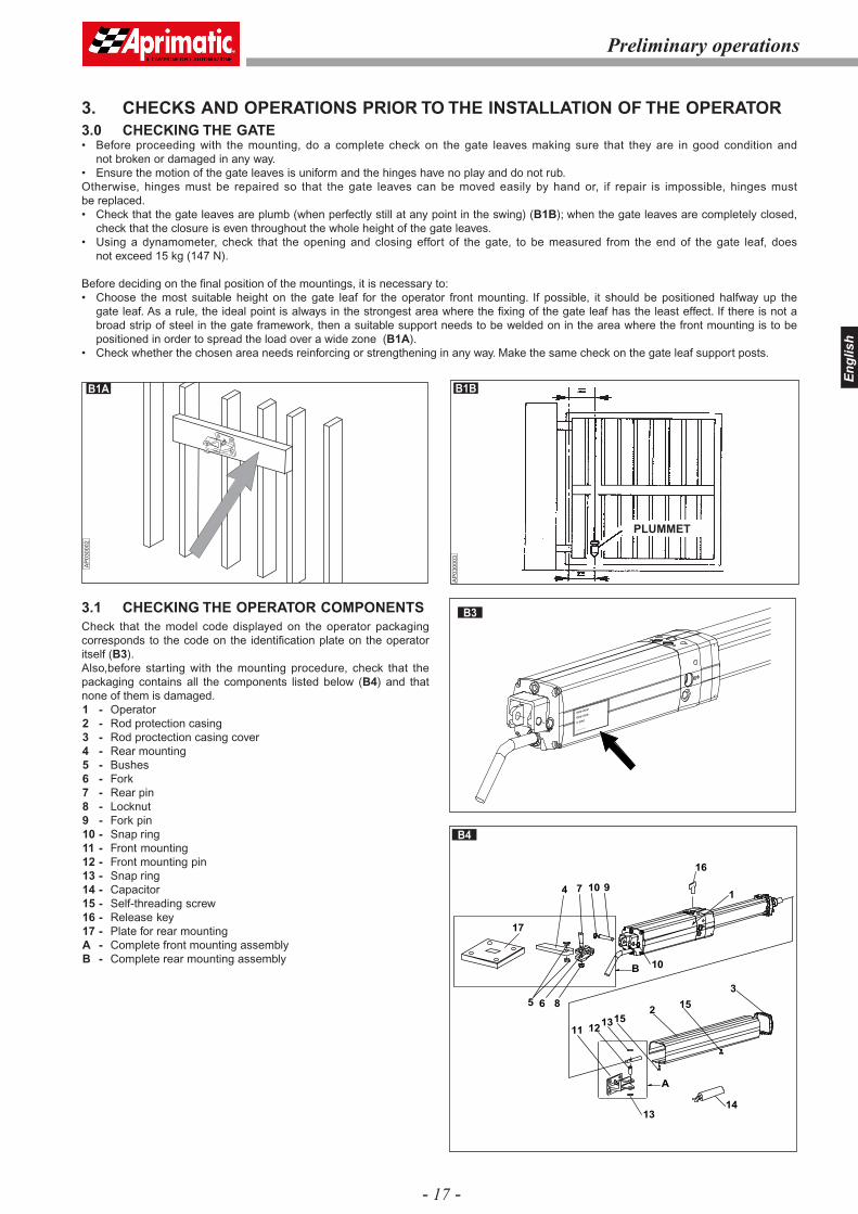
3. CHECKS AND OPERATIONS PRIOR TO THE INSTALLATION OF THE OPERATOR3.0 CHECKING THE GATE• Before proceeding with the mounting, do a complete check on the gate leaves making sure that they are in good condition and
not broken or damaged in any way. • Ensure the motion of the gate leaves is uniform and the hinges have no play and do not rub.Otherwise, hinges must be repaired so that the gate leaves can be moved easily by hand or, if repair is impossible, hinges must be replaced.• Check that the gate leaves are plumb (when perfectly still at any point in the swing) (B1B); when the gate leaves are completely closed,
check that the closure is even throughout the whole height of the gate leaves.• Using a dynamometer, check that the opening and closing effort of the gate, to be measured from the end of the gate leaf, does
not exceed 15 kg (147 N).
Before deciding on the fi nal position of the mountings, it is necessary to:• Choose the most suitable height on the gate leaf for the operator front mounting. If possible, it should be positioned halfway up the
gate leaf. As a rule, the ideal point is always in the strongest area where the fi xing of the gate leaf has the least effect. If there is not a broad strip of steel in the gate framework, then a suitable support needs to be welded on in the area where the front mounting is to be positioned in order to spread the load over a wide zone (B1A).
• Check whether the chosen area needs reinforcing or strengthening in any way. Make the same check on the gate leaf support posts.
16
B
A
13
1
13
2
3
4
5
7 10 9
6
10
14
8
15
15
11 12
17
B3
B4
Preliminary operations
eee eee
eee eee
x eee
............
AP
0300
02
B1A B1B
3.1 CHECKING THE OPERATOR COMPONENTSCheck that the model code displayed on the operator packaging corresponds to the code on the identifi cation plate on the operator itself (B3).Also,before starting with the mounting procedure, check that the packaging contains all the components listed below (B4) and that none of them is damaged.1 - Operator2 - Rod protection casing3 - Rod proctection casing cover4 - Rear mounting5 - Bushes6 - Fork 7 - Rear pin8 - Locknut9 - Fork pin10 - Snap ring11 - Front mounting12 - Front mounting pin13 - Snap ring14 - Capacitor15 - Self-threading screw16 - Release key17 - Plate for rear mountingA - Complete front mounting assemblyB - Complete rear mounting assembly
PLUMMET
AP
0300
03
- 18 -
En
glis
h
Installation
3.2 MOUNTING TOOLSTo mount the operator, a number of preparatory on-site jobs need to be done on the structure that is to be moved; for this, it is better to be equipped with the correct tools, so that the installer is able to work independently.
CautionThe list of required tools is shown in the illustration and table (B5).
DynamometerPlumb lineSpirit level (3-D)Graphitized greaseOil - AprimOil HC 13 (specially formulated for Aprimatic)Zinc-spray cylinderAnti-rust paintPaintbrushesThinner for cleaning paintbrushesWire brushFilesHacksawsScribersHammerChisel for steel and masonryDetergent wipesPaper hand-towelsFirst aid kit
Electric disk grinder - 230 VProtective gogglesElectric welder - min. power 230 V/100 amp.Protective maskElectrodes - min. ø 2Soldering ironSuitably powered electric drill - 230 VDrill bitsHollow cutter ø 67 for photocells and control panel mounting holesExtension cable for welderElectric cable, cross-section 1.5 mm2, various colours + various types of terminalsElectrical scissorsPliers for cable terminalsTester1/20 gaugeRuleGoniometer
B5
POS. TOOL
1
2
Screwdriver
Gripper for snap ring on shaft
Screwdriver TC
Combined wrench 12
Combined wrench 13
Combined wrench 14
Combined wrench 17
USAG 326/5x150
USAG 128 P/1025
3 USAG 326 TC/2
4 USAG 285/12
5 USAG 285/13
6 USAG 285/14
7 USAG 285/17
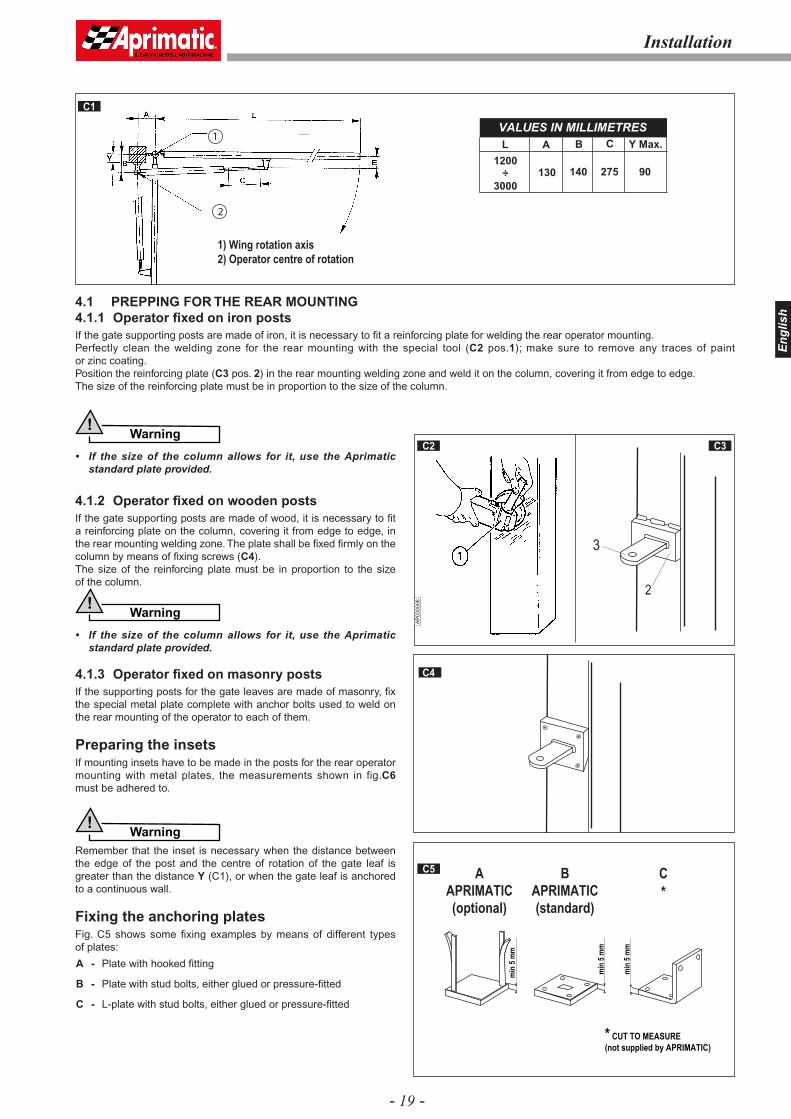
4. INSTALLING THE OPERATOR4.0 POSITIONING THE MOUNTINGSThe following table (C1) indicates the recommended data for defi ning the position of the operator mountings in relation to the centre of rotation of the gate leaf. The distances A and B will give:• The useful stroke length (C) of the piston• The peripheral velocity of the gate leaf• The angle of maximum opening of the gate leaf• The holding capacity of the lock in relation to distance E (which must always be less than B when the operator is fitted with a
hydraulic lock); the distance E is obtained, in practice, by measuring the distance between front mounting fulcrum and gate hinge axis (see fi g. C1).
Caution• The sum A+B corresponds to the useful stroke length of the piston (C) for a 90° opening of the gate leaf. • The minimum value of distances A and B is 70 mm; the maximum one is indicated in column B of the table (see fi g. C1).• Distances A and B must be as equal as possible in order to have a uniform peripheral velocity.• If the gate leaf shall be opened by more than 90°, fi rst of all fi nd the best A and B measurements for mounting, then reduce
distance B to the desired opening angle, making sure, by checking the distance Y, that the corner of the post does not interfere with the operator action.
Warning!
• The greater the distance B in relation to E, the more effi cient the holding capacity of the hydraulic lock (for all types of operator).• If the gate leaf is closed with an electric lock, then E must always be less than or equal to B (never greater).
12
2
6 5 4 7 3
- 19 -
En
glis
h
Installation
1
2
VALUES IN MILLIMETRES
L A B C Y Max.
130 140 275 90
1200
÷
3000
C1
AP
0300
08
C2 C3
3
2
4.1 PREPPING FOR THE REAR MOUNTING4.1.1 Operator fi xed on iron postsIf the gate supporting posts are made of iron, it is necessary to fi t a reinforcing plate for welding the rear operator mounting.Perfectly clean the welding zone for the rear mounting with the special tool (C2 pos.1); make sure to remove any traces of paint or zinc coating.Position the reinforcing plate (C3 pos. 2) in the rear mounting welding zone and weld it on the column, covering it from edge to edge.The size of the reinforcing plate must be in proportion to the size of the column.
Warning!
• If the size of the column allows for it, use the Aprimatic standard plate provided.
4.1.2 Operator fi xed on wooden postsIf the gate supporting posts are made of wood, it is necessary to fi t a reinforcing plate on the column, covering it from edge to edge, in the rear mounting welding zone. The plate shall be fi xed fi rmly on the column by means of fi xing screws (C4).The size of the reinforcing plate must be in proportion to the size of the column.
Warning!
• If the size of the column allows for it, use the Aprimatic standard plate provided.
4.1.3 Operator fi xed on masonry postsIf the supporting posts for the gate leaves are made of masonry, fi x the special metal plate complete with anchor bolts used to weld on the rear mounting of the operator to each of them.
Preparing the insetsIf mounting insets have to be made in the posts for the rear operator mounting with metal plates, the measurements shown in fig.C6 must be adhered to.
Warning!
Remember that the inset is necessary when the distance between the edge of the post and the centre of rotation of the gate leaf is greater than the distance Y (C1), or when the gate leaf is anchored to a continuous wall.
Fixing the anchoring platesFig. C5 shows some fi xing examples by means of different types of plates:
A - Plate with hooked fi tting
B - Plate with stud bolts, either glued or pressure-fi tted
C - L-plate with stud bolts, either glued or pressure-fi tted
C5
C4
min
5 m
m
* CUT TO MEASURE
(not supplied by APRIMATIC)
min
5 m
m
min
5 m
m
B
APRIMATIC
(standard)
A
APRIMATIC
(optional)
C
*
1) Wing rotation axis2) Operator centre of rotation
- 20 -
En
glis
h
PRESSURE FITTING
Type B plate
Type C plate
AP
0300
14
C8RECOMMENDED GLUE FITTING
(other glue fitting systems
are available on the market)
Type B plateType C plateA
P03
0015
C8
Installation
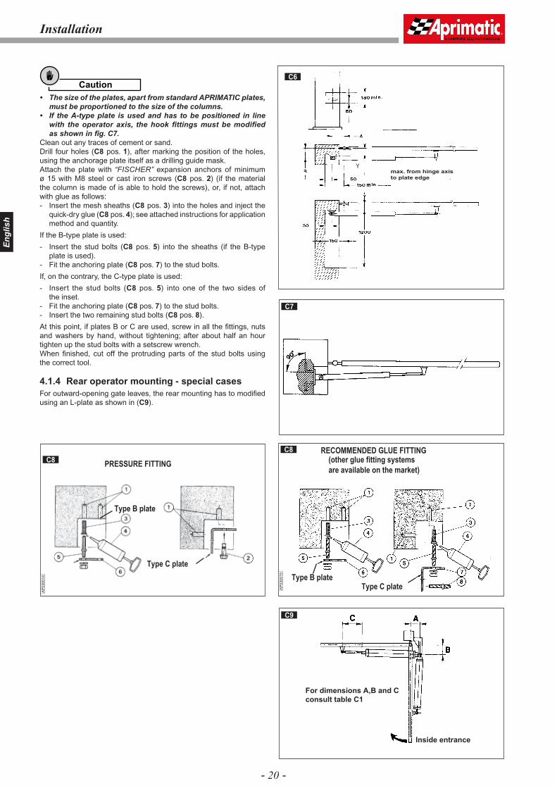
Caution• The size of the plates, apart from standard APRIMATIC plates,
must be proportioned to the size of the columns. • If the A-type plate is used and has to be positioned in line
with the operator axis, the hook fi ttings must be modifi ed as shown in fi g. C7.
Clean out any traces of cement or sand.Drill four holes (C8 pos. 1), after marking the position of the holes, using the anchorage plate itself as a drilling guide mask.Attach the plate with “FISCHER” expansion anchors of minimum ø 15 with M8 steel or cast iron screws (C8 pos. 2) (if the material the column is made of is able to hold the screws), or, if not, attach with glue as follows:- Insert the mesh sheaths (C8 pos. 3) into the holes and inject the
quick-dry glue (C8 pos. 4); see attached instructions for application method and quantity.
If the B-type plate is used:
- Insert the stud bolts (C8 pos. 5) into the sheaths (if the B-type plate is used).
- Fit the anchoring plate (C8 pos. 7) to the stud bolts.
If, on the contrary, the C-type plate is used:
- Insert the stud bolts (C8 pos. 5) into one of the two sides of the inset.
- Fit the anchoring plate (C8 pos. 7) to the stud bolts.- Insert the two remaining stud bolts (C8 pos. 8).
At this point, if plates B or C are used, screw in all the fi ttings, nuts and washers by hand, without tightening; after about half an hour tighten up the stud bolts with a setscrew wrench.When fi nished, cut off the protruding parts of the stud bolts using the correct tool.
4.1.4 Rear operator mounting - special casesFor outward-opening gate leaves, the rear mounting has to modifi ed using an L-plate as shown in (C9).
Ymax. from hinge axis
to plate edge
C7
C6
C9
For dimensions A,B and C
consult table C1
Inside entrance
- 21 -
En
glis
h
AP
0300
17
AP
0300
16
C9 C10
C12 C13
Installation
4.2 FIXING THE REAR OPERATOR MOUNTING Position the rear mounting (B4 pos. 4) at the height previously measured and weld it on the anchorage plate with two weld points (C9).Check the lengthwise and crosswise alignment of the mounting (C10) with a water level.Complete the welding and clean away the residues with a wire brush.
Warning!
• Before welding, ensure that there are no bushes (B4 pos. 5) in the mounting, and that the fi tting hole is properly protected from weld residues.
• When the welded zone has cooled down, apply a coat of anti-rust paint.
4.3 TEMPORARY INSTALLATION OF THE OPERATORTemporarily mount the operator to fi nd the correct fi xing position of the front mounting.
Warning!
Handle the operator with care during assembly.Fit the fork (C11 pos. 1) to the operator bottom. Lock the fork with the special pin (C11 pos. 2) and fi x both with the two snap rings (C11 pos. 3).Fit the two vibration damping bushes (C12 pos. 4) above and below the mounting.Position the fork of the operator on to the mounting and lock it with the vertical pin (C13 pos. 5) after greasing abundantly.
Warning!
Grease both the pin and the housings abundantly.
C11
1
2
3
3
- 22 -
En
glis
h
Installation
AP
0300
26
C17
C15
4.4 POSITIONING THE FRONT MOUNTINGSmear the hole of the operator rod with grease (C14 pos. 1). Position the end of the rod into the front mounting (C14 pos. 2), then fi t the locking pin (C14 pos. 3) without tightening the snap rings (C14 pos. 4). If it has been decided to use the maximum useful length of the rod (distance A+B = useful piston stroke length), proceed as follows:
• Position the key (see paragraph 6) onto the unlock screw and rotate counter-clockwise to hand-unlock the operator.
• Slowly extend the rod to end stroke.
• Withdraw the rod of 5 mm.
• Protect the rod (C17 pos. 3).
• Perfectly clean the welding zone for the front mounting with a suitable tool (C15 pos. 4); be especially sure to remove any traces of paint or zinc coating.
Warning!
• Check the strength of the mounting zone; if necessary, fi t a strengthening plate of the correct size; the strengthening plate is especially important with gate leaves made from thin sheet steel.
• When cleaning the mounting zone for the operator front mounting, remove the operator and protect it from fl ying sparks.
Rest a water level (C16 pos. 1) on the operator body (C16 pos. 2) and level the operator.
Weld the front mounting of the rod to the gate leaf with two weld-points, protecting the rod from weld residues with a clean cloth (C17 pos. 4).
Withdraw the rod from the front mounting and remove the operator itself from the temporary mountings to complete the welding. Protect the pin (using a clean cloth or adhesive tape) from weld residues, then clean off the residues with a wire brush. After cooling, apply a coat of rustproof paint to the welded zone.
Warning!
• While welding the points on the front mounting with the electrode, always cover the rod with a clean cloth; a splinter of molten metal can cause irreparable damage to the machined surface and make the operator unusable.
• During welding, the operator must be disconnected from the electricity supply.
C14
300 mm
C16
- 23 -
En
glis
h
AP
0300
32
C18 C26
E1
1
AP
0300
52
2
1
E2
E3 E4
Installation
AP
0300
51
4.5 FINAL INSTALLATION OF THE OPERATOR
4.5.1 Mechanical fi xing
Fix both ends of the operator to the respective mountings.
Front fi xingSmear the front anchoring pin of the ball-joint and the rod with graphitized grease.Position the end of the rod into the front mounting (C11 pos. 4). Fit the locking pin (C11 pos. 5) and fi x with the snap rings.
Rear fi xingFix the operator to the rear mounting using the fork pin (C18 pos. 3) and the relevant lock nut (C18 pos. 4).With the gate leaf fully closed, re-check that the rod comes out from the operator of the defi ned measure.
4.5.2 Checking the motion
Warning!
• When the mounting is completed, neutralize the hydraulic lock (if present in the operators) by turning the correct key through 180° counter-clockwise, and move the gate-leaves manually to check on the smoothness of the movement; this should be done very slowly, otherwise the operators will take in air and, consequently, will have to be bled.
• Open and close the gate leaf to check that the operator can move freely without rubbing and without going against either the gate leaf or the gate post.
• After making the checks, reset the hydraulic lock by turning the release key fully in a clockwise direction.
4.5.3 Electrical connectionMake the electrical connection according to the wiring diagram (D1) - see paragraph “System electrical connection”.Connect the supplied capacitor (B4 pos. 12) to the electric control unit according to the wiring diagram of the unit itself.
4.5.4 Fitting the protection casing and removing the bleed screw
Fit the protective casing (E1 pos. 1) to rod and insert into the operator.
Hold the casing bottom (E2 pos. 2) in position with a cross-head screwdriver (E2 pos. 3). Fit the push-on cover (E3 pos. 2) on to the protective casing (E3 pos.1).Tighten the fi xing screw of the protective casing (E4 pos.1).On completion of the assembly, remove the bleed screw (E5 pos. 4) using a CH7 hexagonal wrench.
- 24 -
En
glis
h
Final operations
E7
Fit the protective sheath to the power supply cable (E5 pos. 5)
if necessary.
Caution
One drop of hydraulic oil coming out of the duct created by the
screw elimination (E5 pos. 4) is normal.
InformationAfter installation, an appropriate warning sign must be attached
to the gate (E6 pos. 2.)
When completely assembled, the operator should appear as shown in the fi gure (E6 pos. 1).
4.5.5 Bleeding
Warning!
Before proceeding in setting the operator, bleed it.
Start the operator after having checked the setting of the pressure relief valves and move it to stroke end either in open or close position. Rotate on the key (see paragraph 6) and lock and unlock the operator a dozens of times.
5. CHECKS AND ADJUSTMENTS
5.0 CHECKING AND ADJUSTING THE THRUST FORCE
With the gate leaf moving, measure the thrust force at the end of the gate leaf, using a dynamometer (E7 pos. 1). The thrust force must never exceed 15 Kg (147 N). If necessary, adjust the working pressure of the operator.Using a broad, flat-headed screwdriver, turn the control valves clockwise to increase the pressure and counter-clockwise to reduce it.Adjust both opening (silver - E8 pos. 2) and closing pressure (gold - E8 pos. 1).
Caution• The opening thrust of the gate leaf should be set slightly
higher than the closing thrust.• After making the settings, make another check with the
dynamometer to see if the thrust force corresponds to the setting; if it doesn’t, then the setting needs to adjusted again.
• If the gate leaf requires an excessively high pressure to move it, then make another thorough check of the mechanical parts, the plumb and the free movement of the gate leaf itself.
6.0 EMERGENCY MANOEUVRE - USE OF THE MANUAL RELEASE
AP
0300
40
E5
E6
Aprimatic
Aprim atic
Aprim atic
Aprimatic
Aprimatic
2
1
In the event of a power failure, release the operator in order to open the gate by hand.
To gain access to the release valve, it is enough to loosen the screw (E9 pos. 2) and open the small cover (E9 pos. 3) by rotating it.
Unlock the operator by turning the triangular key provided (E9 pos. 1) counter-clockwise.
After the operation, re-lock the operator by turning the key clockwise.
Warning!
After locking and releasing operations, remember to re-close the cover.
- 25 -
En
glis
h
Notes for the user✂
SPACE RESERVED TO THE INSTALLERPLEASE, SUPPLY THIS PAGE TO THE USER
By operating the opening control, the leaf does not move and the electric motor of the operator does not run.
No power supply. Turn the power on.
Defective fuse. Replace the defective fuses with new ones having
The power cable of the operator is damaged.Replace the power cable and find and rectify the fault.
By operating the opening control, the electric motor of the operator runs but the leaf does not move.
If the operator has a hydraulic release,check that the release valve setting is Turn the valve fully in a clockwise direction (E9 pos.1).
During the motion, the operator jerks.
Detach the operator from its front mountingProbably air in the cylinder.
Oil in the cylinder not enough. Check for oil leaks; if any, address to an
APRIMATIC Repair Centre.The front and rear operator mountings Repair or strengthen the mountings.
Fault type Probable cause Solution
closed.
move or have been fitted incorrectly.
If the operator doesn't have a hydraulic release, adjiust the opening pressure setting.
If the operator has been exposed to the sun for a long period, with the gate closed, check thatthe operator piston is not in the fully advancedposition, i.e. with the rod completely out.
Screw the pressure setting valve clockwise�(par.5 - E8 pos.2)
Check the operator mounting, as described inthis manual.Check the measure of the piston stroke.
and make a few opening and closing movements; then re-fit to the front mounting.
the same amperage.
E9
E8
2
1
2
1 3
7. NOTES FOR THE INSTALLER
7.0 Maintenance
InformationPeriodically check the proper functioning of the operator. Do this check at least every 12 months
Warning!
Maintenance must be performed only by skilled technicians.
Warning!
Before doing any maintenance job, turn the operator off by means of the differential switch of the electric system.• Grease the joints with graphitized grease every year. • Check the general condition of the gate structure. • Check the mechanical resistance of hinges, operator mountings
and stops. • Ensure the installed safety devices are in working order (photocells,
rubber barriers,…) and adjust the thrust force at the end of the gate leaf (max. 147 N).
• Ensure the electrical system and the differential switch are effi cient.
• Check the setting of the pressure relief valve. • Check the tightening of the safety lock. • Depending on the use of the operator, check the oil level of


![TERMS AND CONDITIONS zt{ / aGb]h · TERMS AND CONDITIONS zt{ / aGb]h ... 8](https://static.documents.pub/doc/80x56/5ecb9c6360da650bc655f7ac/terms-and-conditions-zt-agbh-terms-and-conditions-zt-agbh-8.jpg)


