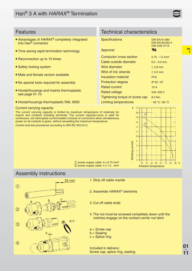
Current carrying capacityThe current carrying capacity is limited by maximum temperatureof materials for inserts and contacts including terminals. Thecurrent capacity-curve is valid for continuous, not interruptedcurrent-loaded contacts of connectors when simultaneous poweron all contacts is given, without exceeding the maximum tempe-rature.
Control and test procedures according to DIN IEC 60 512-3.
Specifications DIN VDE 0627DIN VDE 0110DIN EN 61 984
Approvals , , SEV
InsertsNumber of contacts 3, 4, 10, 16, 32 (2 x 16) + PE
Electrical data acc. to DIN EN 61 984
Han® 3 A, 4 A 10 A 230/400 V 4 kV 3
Working currentWorking voltage conductor – groundWorking voltage conductor – conductorRated impulse voltagePollution degreeor 10 A 250 V 4 kV 3
Han® 10 A, 16 A 16 A 250 V 4 kV 3
Working currentWorking voltageRated impulse voltagePollution degree– Pollution degree 2 also 16 A 230/400 V 4 kV 2
Working voltageacc. to UL/CSA 600 VInsulation resistance ≥ 1010 ΩMaterial PolycarbonateLimiting temperatures - 40 OC / +125 OCFlammability acc. to UL 94 V 0Mechanical working life
- mating cycles ≥ 500
ContactsMaterial copper alloySurface - hard-silver plated 3 µm Ag
- mm2 1.0 - 2.5 mm²- AWG 18 - 14- Tightening/test torque 0.5 Nm Han 10/16 A
0.25 Nm Han 3/ 4 A
Hoods/Housings thermoplastic Han® 3 A / 4 AMaterial Polycarbonate RAL 7032Locking element Polyamide RAL 7032Flammability acc. to UL 94 V 0Hoods/Housings seal NBRLimiting temperatures - 40 OC / +125 OCDegree of protection acc. to DIN EN 60 529 for coupled connector IP 65 / 67
Hoods/Housings metalMaterial Han® 3 A / 4 A die cast zincMaterial Han® 10 A / 16 A die cast aluminiumLocking element Han® 3 A / 4 A steel, zinc platedLocking element Han® 10 A / 16 A Han-Easy Lock®
Hoods/Housings seal NBRLimiting temperatures - 40 OC / +125 OCDegree of protection acc. to DIN EN 60 529 for coupled connector
Han® 3 A / 4 A IP 44IP 65 / 67 with sealing screw
09 20 000 9918Han® 10 A / 16 A IP 65
further selectionof hoods/housings chapter 30 / chapter 31
Current carrying capacityThe current carrying capacity is limited by maximum temperature of materials forinserts and contacts including terminals. The current capacity-curve is valid forcontinuous, not interrupted current-loaded contacts of connectors when simultaneouspower on all contacts is given, without exceeding the maximum temperature.
Control and test procedures according to DIN IEC 60 512-3.
1. Strip off cable mantle
2. Assemble HARAX® elements
3. Cut off cable ends
4. The nut must be screwed completely down until thenotches engage on the contact carrier nut latch
a = Screw capb = Sealingc = Splice ring
Included in delivery:Screw cap, splice ring, sealing
● Advantages of HARAX® completely integrated into Han® connector
● Time saving rapid termination technology
● Reconnection up to 10 times
● Safety locking system
● Male and female version available
● No special tools required for assembly
● Hoods/housings and inserts thermoplastic see page 01.10
● Hoods/housings thermoplastic RAL 9005
Wor
king
cur
rent
Ambient temperature➀ power supply cable: 4 x 0.75 mm²➁ power supply cable: 4 x 1.5 mm²
Specifications DIN EN 61 984DIN EN 60 352-4DIN VDE 0110
Approval
Conductor cross section 0.75 - 1.5 mm²
Cable outside diameter 6.0 - 9.0 mm
Wire diameter ≤ 2.8 mm
Wire of ind. strands ≥ 0.2 mm
Insulation material PVC
Protection degree IP 65 / 67
Rated current 10 A
Rated voltage 230 / 400 V
Tightening torque of screw cap 8.0 Nm
Limiting temperatures - 40 °C / 85 °C
01.12
HanA
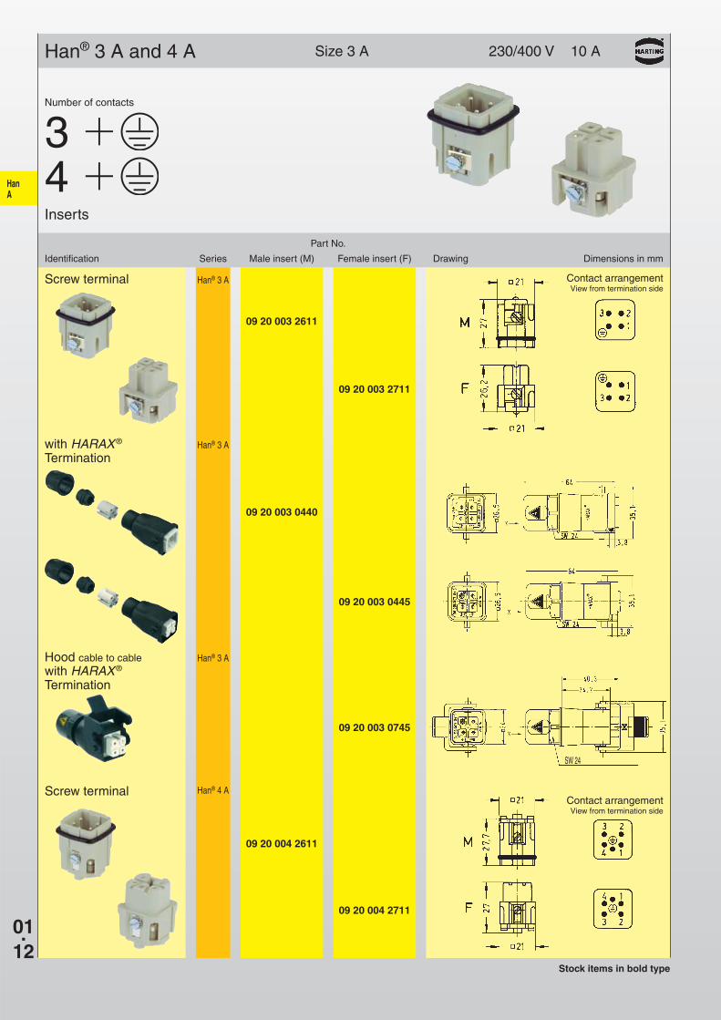
09 20 004 2711
09 20 004 2611
Han® 4 A
09 20 003 2711
09 20 003 2611
Han® 3 A
09 20 003 0445
09 20 003 0440
09 20 003 0745
Han® 3 A
Han® 3 A
230/400 V 10 A
SW 24
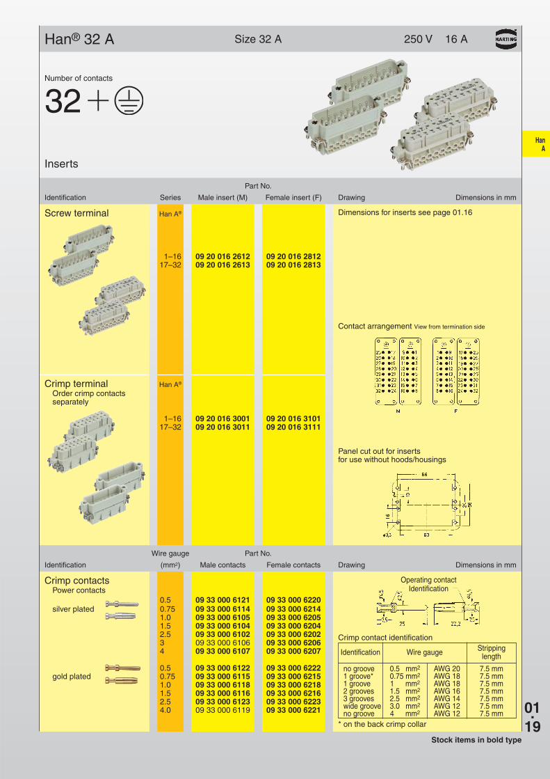
Size 3 AHan® 3 A and 4 A
Part No.
Identification Series Male insert (M) Female insert (F) Drawing Dimensions in mm
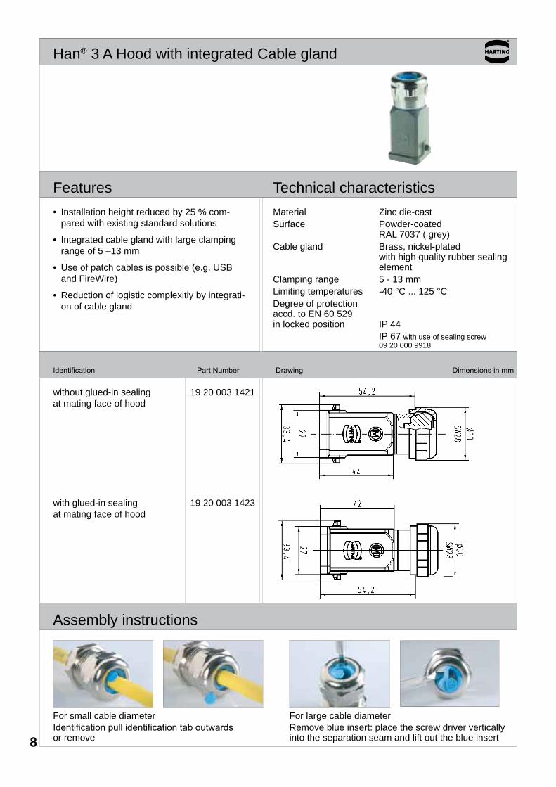
For small cable diameter Identificationpullidentificationtaboutwardsor remove
For large cable diameter Remove blue insert: place the screw driver vertically into the separation seam and lift out the blue insert
• Installation height reduced by 25 % com-pared with existing standard solutions
• Integrated cable gland with large clamping range of 5 –13 mm
• Use of patch cables is possible (e .g . USB and FireWire)
• Reduction of logistic complexitiy by integrati-on of cable gland
Material Zinc die-castSurface Powder-coated
RAL 7037 ( grey)Cable gland Brass, nickel-plated
with high quality rubber sealing element
Clamping range 5 - 13 mmLimiting temperatures -40 °C . . . 125 °CDegree of protectionaccd . to EN 60 529in locked position IP 44 IP 67 with use of sealing screw
09 20 000 9918
�
01.14
HanA
A B
C
A 09 20 003 54071)3)1)
09 20 003 54082)3)4)
B 09 20 003 54452)1)1)
09 20 003 54461)1)1)
09 20 003 54472)3)4)
C 09 20 003 54481)1)1)
09 20 003 54492)4)1)
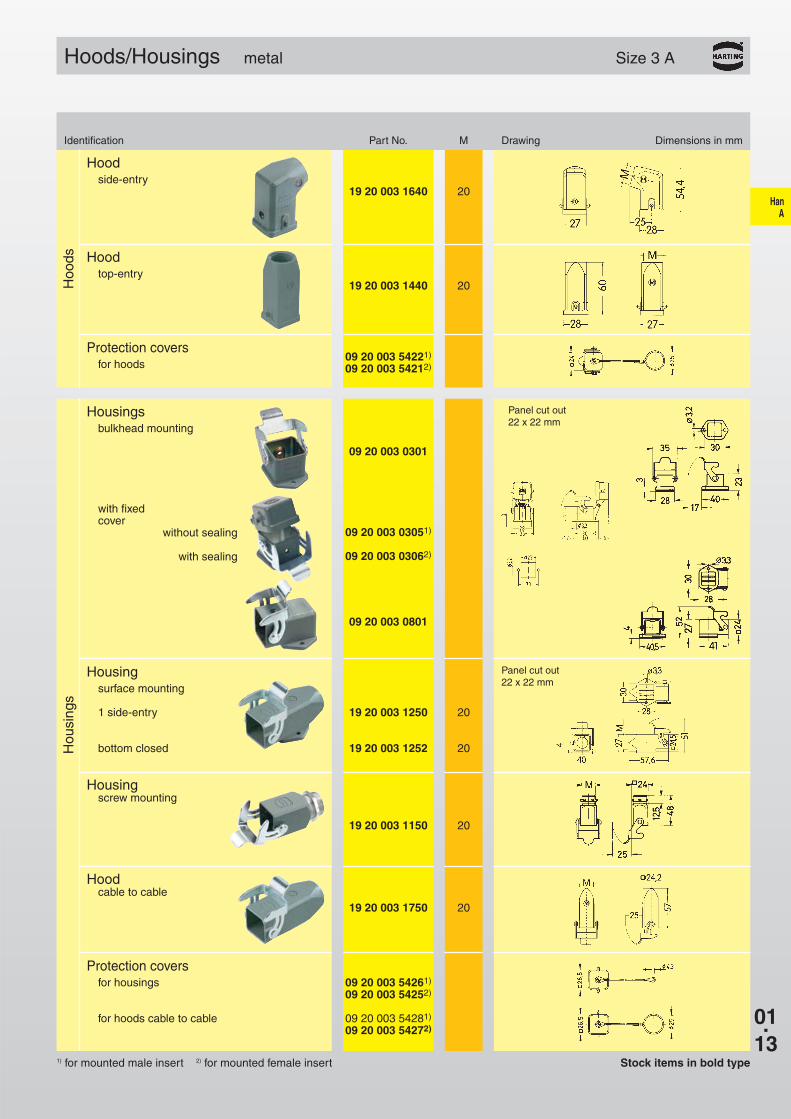
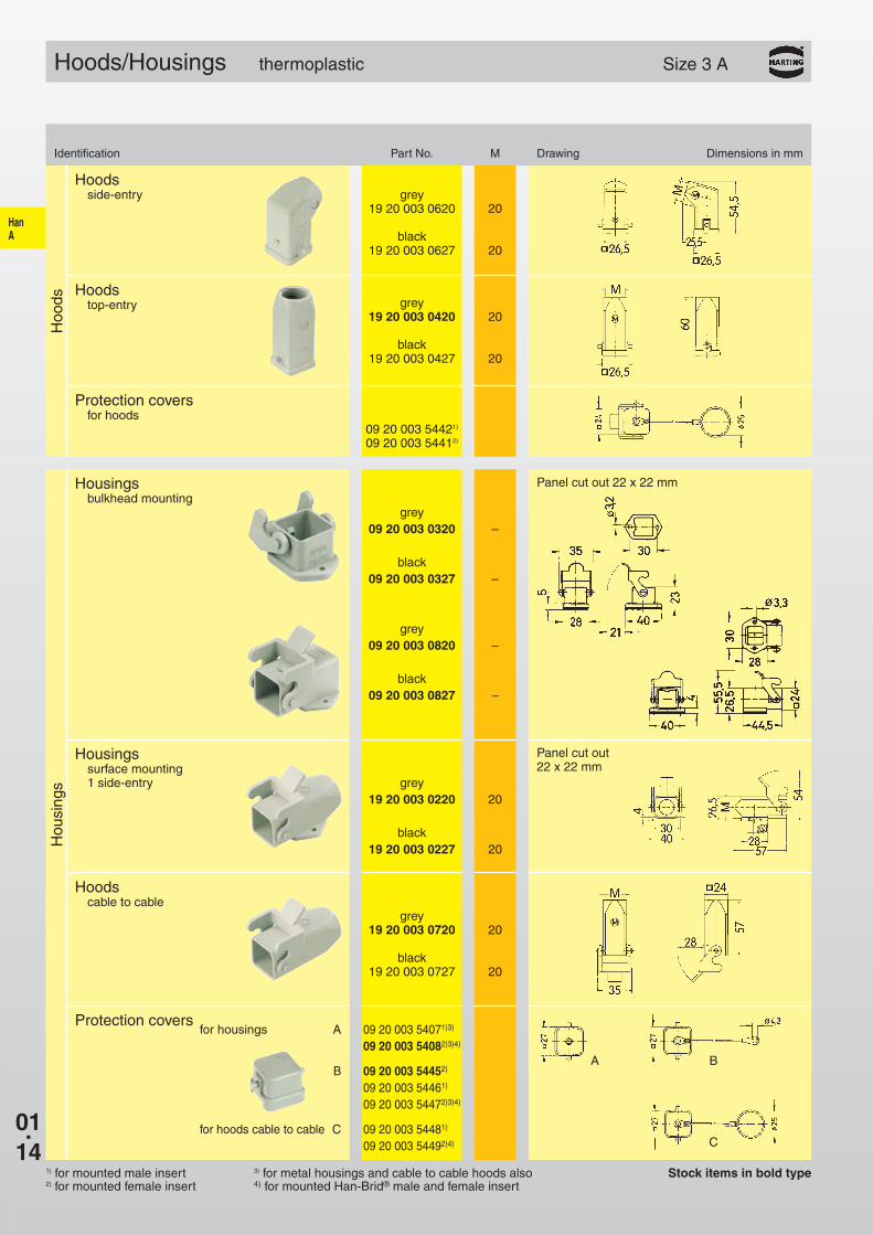
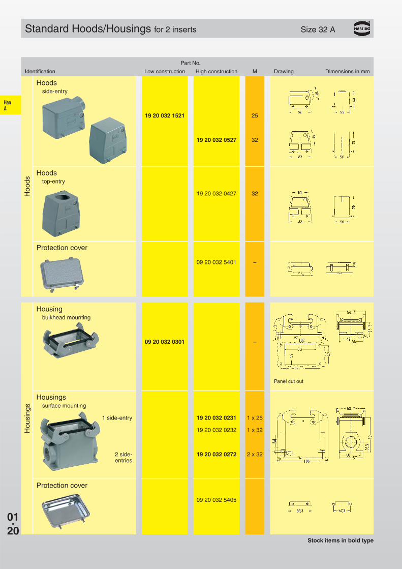
Hoods/Housings thermoplastic Size 3 A
Identification Part No. M Drawing Dimensions in mm
Hoo
ds
Hoodsside-entry grey
19 20 003 0620 20
black19 20 003 0627 20
Protection coversfor hoods
09 20 003 54421)
09 20 003 54412)
Hou
sing
s
Housings bulkhead mounting
grey09 20 003 0320 –
black09 20 003 0327 –
grey09 20 003 0820 –
black09 20 003 0827 –
Housingssurface mounting1 side-entry grey
19 20 003 0220 20
black19 20 003 0227 20
Hoods cable to cable
grey19 20 003 0720 20
black19 20 003 0727 20
Panel cut out 22 x 22 mm
Panel cut out 22 x 22 mm
grey19 20 003 0420 20
black19 20 003 0427 20
Hoodstop-entry
Stock items in bold type1) for mounted male insert2) for mounted female insert
3) for metal housings and cable to cable hoods also4) for mounted Han-Brid® male and female insert


![· PDF file-co co 230. 700, 595, 140, 33, 17, , 162, 50, 27, 10, 845, 0 00 000 0 00 000 0 00 2 01"] 000 7 20 000 70, 33, 300 s 600, 534, 3 00 000 FL] 400](https://static.documents.pub/doc/80x56/5aac9c2a7f8b9aa9488d3987/co-230-700-595-140-33-17-162-50-27-10-845-0-00-000-0-00-000-0-00-2.jpg)

