32
Contents1 New Generation of Power Management Solution Kevin Ho
5 OPC UA: New Generation Technology of the Standard Industrial Communication
Cony Yu
9 WISE-5231 Intelligent Multifunction IoT I/O Concentrator Rick Lee
15 Residential/Commercial Building Leakage Monitoring Application Phileo Lin
17 Lighting and Air Conditioning Management System in Hospital Austin Lin
19 PAC in Railway Signaling Application Cony Yu
22 ZigBee Application - Emergency Bell Alarm System YY Chang
25 ZigBee Application - Route Management System for AGV YY Chang
ICP DAS CO.LTDNo. 111, Guangfu N. Rd., Hukou Township, Hsinchu County 30351, Taiwan, R.O.C.TEL: +886-3-597-3366 FAX: +886-3-597-3733Website: http://http://www.icpdas.com/E-mail: [email protected]
For changes of address or subscr ipt ion problems, contact us at [email protected]
Copyright © ICP DAS CO., LTD. All Rights Reserved. All rights reserved. No part of this magazine may be republished, reprinted or redistributed in any forms, including electronic, without written consent from the publisher.
Application
1
New Generation of Power Management SolutionBy Kevin Ho
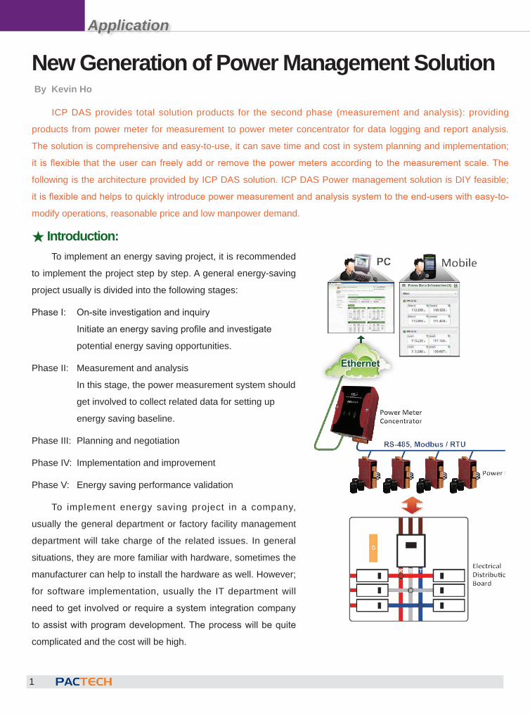
ICP DAS provides total solution products for the second phase (measurement and analysis): providing
products from power meter for measurement to power meter concentrator for data logging and report analysis.
The solution is comprehensive and easy-to-use, it can save time and cost in system planning and implementation;
it is flexible that the user can freely add or remove the power meters according to the measurement scale. The
following is the architecture provided by ICP DAS solution. ICP DAS Power management solution is DIY feasible;
it is flexible and helps to quickly introduce power measurement and analysis system to the end-users with easy-to-
modify operations, reasonable price and low manpower demand.
★ Introduction:To implement an energy saving project, it is recommended
to implement the project step by step. A general energy-saving
project usually is divided into the following stages:
Phase I: On-site investigation and inquiry
Initiate an energy saving profile and investigate
potential energy saving opportunities.
Phase II: Measurement and analysis
In this stage, the power measurement system should
get involved to collect related data for setting up
energy saving baseline.
Phase III: Planning and negotiation
Phase IV: Implementation and improvement
Phase V: Energy saving performance validation
To implement energy saving project in a company,
usually the general department or factory facility management
department will take charge of the related issues. In general
situations, they are more familiar with hardware, sometimes the
manufacturer can help to install the hardware as well. However;
for software implementation, usually the IT department will
need to get involved or require a system integration company
to assist with program development. The process will be quite
complicated and the cost will be high.
Application
2
Ethernet / RS-485 converter: not required, the cost can be savedMV146-MCM is a Modbus/RTU to Modbus/TCP converter that allows SCADA software to access the data on
the power meter via Ethernet. Using the PMC-5151(ICP DAS Power Meter Concentrator), it provides connection
via Ethernet, the MV146-MCM is no more required and the cost can be saved.
★ Saving Cost:
Cut out the panel board: not required, the cost can be savedICP DAS Power Meter features standard DIN rail installation, comparing to general panel power meter, it does
not require to cut out the panel board for installation.
Software & Trials: the PC and SCADA software can be replaced by the power meter concentrator to save cost and time
To implement the software part in an application by using the SCADA software, the cost usually not only
includes the software license fee and the project development cost; the cost of a PC to perform the SCADA
software is also required. In addition, it always takes long time to communicate with the end users regarding
requirements of all kinds of functionalities and reports.
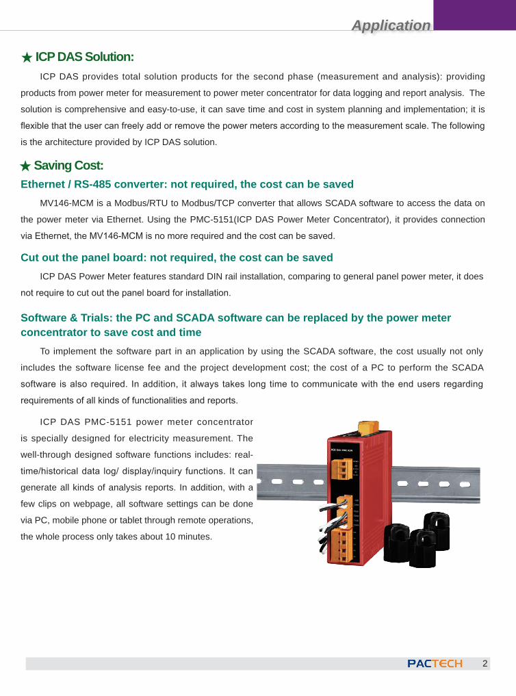
ICP DAS PMC-5151 power meter concentrator
is specially designed for electricity measurement. The
well-through designed software functions includes: real-
time/historical data log/ display/inquiry functions. It can
generate all kinds of analysis reports. In addition, with a
few clips on webpage, all software settings can be done
via PC, mobile phone or tablet through remote operations,
the whole process only takes about 10 minutes.
★ ICP DAS Solution:ICP DAS provides total solution products for the second phase (measurement and analysis): providing
products from power meter for measurement to power meter concentrator for data logging and report analysis. The
solution is comprehensive and easy-to-use, it can save time and cost in system planning and implementation; it is
flexible that the user can freely add or remove the power meters according to the measurement scale. The following
is the architecture provided by ICP DAS solution.
Application
3
For increasing power meters: easy to add devices and expand scale
The software design for PMC-5151 is based on web-based
operations. It is easy to modify the setting when increasing or
decreasing the power meters connected to the PMC-5151.
When it requires to expand the scale, it only needs a qualified
technician to install the power meter, the software parts can be easily taken care of by the users themselves. If use
the SCADA software, unless there is a well-through plan to include the adding/deleting power meter function in
the system at the very beginning; the system integrators usually charge additional fee to modify the software when
require expanding the scale.
★ Conclusion:ICP DAS Power management solution is DIY feasible; it is flexible and helps to quickly introduce power
measurement and analysis system to the end-users with easy-to-modify operations, reasonable price and low
manpower demand.
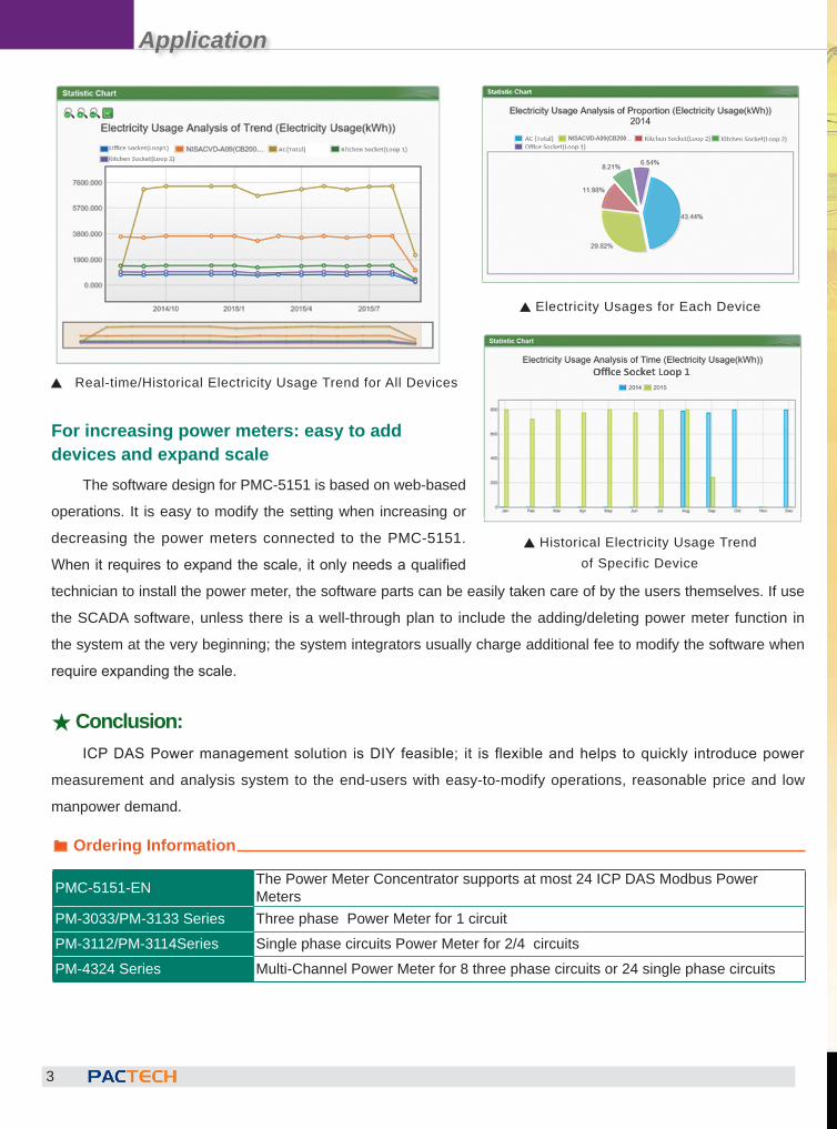
S Real-time/Historical Electricity Usage Trend for All Devices
S Historical Electricity Usage Trend of Specific Device
S Electricity Usages for Each Device
® Ordering Information
PMC-5151-EN The Power Meter Concentrator supports at most 24 ICP DAS Modbus Power Meters
PM-3033/PM-3133 Series Three phase Power Meter for 1 circuitPM-3112/PM-3114Series Single phase circuits Power Meter for 2/4 circuitsPM-4324 Series Multi-Channel Power Meter for 8 three phase circuits or 24 single phase circuits
Application
5
room, etc.
Security: the encryption, authentication, and
validation between the users and the services.
Scalability: add new functionality without affecting
current application and program.
Full-range information modeling: can be used to
define complex information modeling.
3. Reliable DesignIt ensures the arrival sequence of the data and
content validation when performing message
transmission so that helps the decision making for
backend processing and enhances data accuracy
for the data logger software. It is perfect to be
applied to the industrial production or service
system applications that cannot afford long idle
time, by using the OPC UA redundant mode,
it provides redundancy support to resume the
system in real time or in short time.
4. Collaborative technology foundationsOPC Foundation works with various technology
foundations to incorporate data models of different
kinds of technology into the OPC UA; so that it
can achieve interoperability in technology and
improve applications in industrial automation,
OPC UA: New Generation Technology of the Standard Industrial CommunicationBy Cony Yu
The advantage of using OPC UA technology
OPC is designed to play an intermediary role between the automation hardware providers and software developers. By standard OPC interface, the devices and the software can communicate with each other so that the service providers can focus on their specialties without worrying the issues for the communication protocol between the hardware and the software when performing the data transmission. The latest OPC UA technology provides the following features that provide more options to the users.
1. Guarantee seamless integration with the conventional OPC service productsThe data model of UA can be compatible with the conventional OPC. By using “Wrapper”, the UA program can be packaged in Microsoft COM technology. Therefore, the early users do not need to upgrade the conventional OPC, by using “Wrapper”, it can connect to new added OPC UA services.
2. Break the limitations of conventional OPCFunctional equivalent: all classic specifications of COM OPC are included on the UA.Platform independence: can be deployed on the embedded controller or the cloud-based engine
The OPC Unified Architecture (OPC UA), released in 2008, is a standard technology of industrial automation communication. It is a platform that integrates all technology standards such as OPC DA, HA, AE, and etc. It features real-time data reading & writing, historical data accessing, event/warning publishing functions.
By using reliable cross-platform architecture, the OPC UA is no longer need to rely on Windows platform as OPC DA used to be. The OPC products now can be deployed in different environments, such as: on the micro-controller or in the IT engine room. It completes the communication and interoperability between OPC data and events. In addition, for security reason, it also provides user account and authority validation between the Server and Client to protect the privacy of the service and security of the message transmission.
Application
6
UA-5231 Software FeaturesWith the Web-based User Interface, the users
can log in and configure the controller via a web browser on a mobile device or PC.
The IEC 62541 standard OPC UA Server is certified by OPC UA Server OPC Foundation, it helps to integrate the on-site devices to actively upload the data to the application systems without worrying the problem of crossing the platforms.
Implement the Redundancy of OPC UA Server. With the ICP DAS OPC UA Client product, it can provide the redundancy function of the Server to enhance the reliability of the system.
The PID function can combine the remote I/O devices to simulate the PID control system for computing control solutions required on-site.
The Modbus TCP/RTU Master module can connect to all-kinds of standard Modbus TCP/RTU Slave devices via the RS-485, RS-232 or Ethernet ports on the controller. Therefore it is able to provide scalability and flexibility when building a system and meet various requirements for all kinds of applications.
The MQTT Broker is compliance with MQTT v3.1.1 protocol. It supports MQTT message distribution management. The users do not need to build Broker system when using MQTT communications.
With the MQTT communication function, it allows communication between the IoT devices and the OPC UA system. The UA-5231 then conducts the data acquisition and management function; at the same time, the data of the devices managed by UA-5231 can also be converted and published to the IoT system.
production process, ERP, sales enterprise,
building automation, security and smart grid industry, etc. For example, the foundations related to field devices such as: the FDT Group, Fieldbus Foundation, HART Communication Foundation, PROFIBUS & PROFINET International, and the foundations related to building automation such as: BACnet Interest Group and ISA95 of the International Automation Association, etc.
ICP DAS OPC UA SolutionUA-5231 is the first data acquisition controller
developed by ICP DAS which can be integrated with OPC UA Server, MQTT services and other data communication protocols. With the advantages of the RISC-based CPU architecture,compact size and low power consumption; UA- 5231 can be applied to a variety of field environments. Applying OPC UA allows integration the I/O products of ICP DAS with the third-party devices, and then import the data information to the backend SCADA, cloud or other decision making or data logging system. It satisfies the reliability,interoperability and security needs of the industrial automation system and meets the trend of the smart internet.
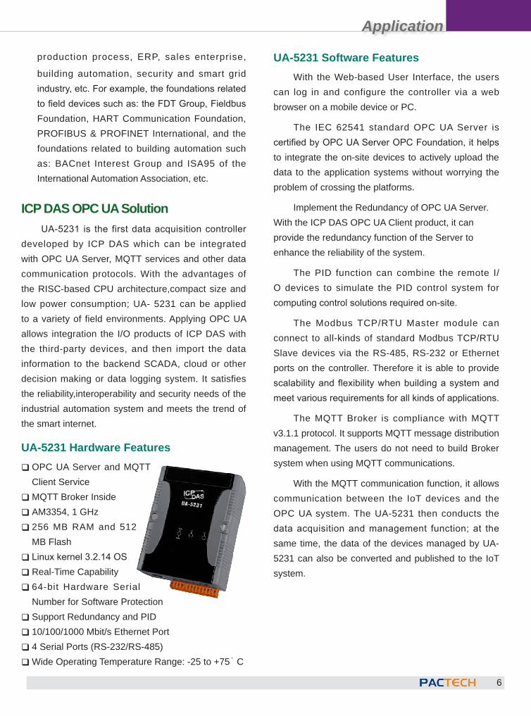
UA-5231 Hardware Features � OPC UA Server and MQTT Client Service �MQTT Broker Inside � AM3354, 1 GHz � 256 MB RAM and 512 MB Flash � Linux kernel 3.2.14 OS � Real-Time Capability � 64-bit Hardware Serial Number for Software Protection � Support Redundancy and PID � 10/100/1000 Mbit/s Ethernet Port � 4 Serial Ports (RS-232/RS-485) �Wide Operating Temperature Range: -25 to +75° C
Application
7
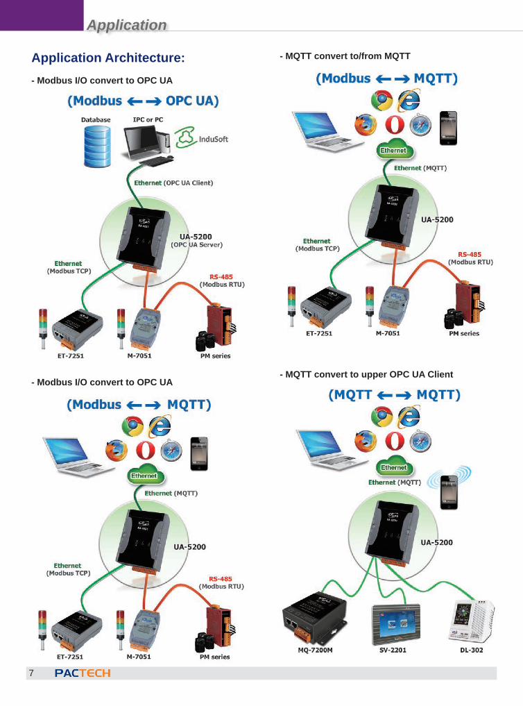
Application Architecture:- Modbus I/O convert to OPC UA
- Modbus I/O convert to OPC UA
- MQTT convert to/from MQTT
- MQTT convert to upper OPC UA Client
Application
8
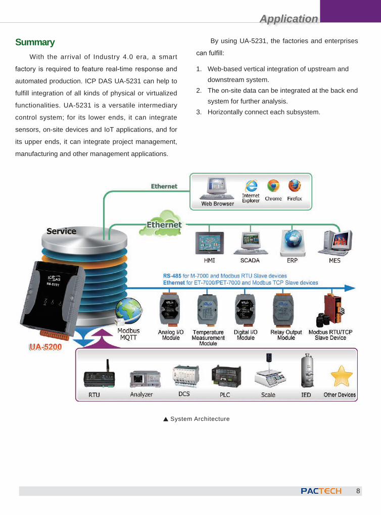
SummaryWith the arrival of Industry 4.0 era, a smart
factory is required to feature real-time response and
automated production. ICP DAS UA-5231 can help to
fulfill integration of all kinds of physical or virtualized
functionalities. UA-5231 is a versatile intermediary
control system; for its lower ends, it can integrate
sensors, on-site devices and IoT applications, and for
its upper ends, it can integrate project management,
manufacturing and other management applications.
By using UA-5231, the factories and enterprises
can fulfill:
1. Web-based vertical integration of upstream and downstream system.
2. The on-site data can be integrated at the back end system for further analysis.
3. Horizontally connect each subsystem.
S System Architecture
Application
9
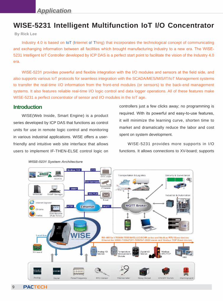
WISE-5231 Intelligent Multifunction IoT I/O ConcentratorBy Rick Lee
Industry 4.0 is based on IoT (Internet of Thing) that incorporates the technological concept of communicating and exchanging information between all facilities which brought manufacturing industry to a new era. The WISE-5231 Intelligent IoT Controller developed by ICP DAS is a perfect start point to facilitate the vision of the Industry 4.0 era.
WISE-5231 provides powerful and flexible integration with the I/O modules and sensors at the field side, and also supports various IoT protocols for seamless integration with the SCADA/MES/MIS/IT/IoT Management systems to transfer the real-time I/O information from the front-end modules (or sensors) to the back-end management systems. It also features reliable real-time I/O logic control and data logger operations. All of these features make WISE-5231 a perfect concentrator of sensor and I/O modules in the IoT age.
IntroductionWISE(Web Inside, Smart Engine) is a product
series developed by ICP DAS that functions as control
units for use in remote logic control and monitoring
in various industrial applications. WISE offers a user-
friendly and intuitive web site interface that allows
users to implement IF-THEN-ELSE control logic on
controllers just a few clicks away; no programming is
required. With its powerful and easy-to-use features,
it will minimize the learning curve, shorten time to
market and dramatically reduce the labor and cost
spent on system development.
WISE-5231 provides more supports in I/O
functions. It allows connections to XV-board; supports
Application
10
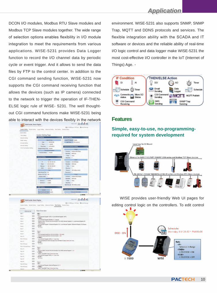
DCON I/O modules, Modbus RTU Slave modules and
Modbus TCP Slave modules together. The wide range
of selection options enables flexibility in I/O module
integration to meet the requirements from various
applications. WISE-5231 provides Data Logger
function to record the I/O channel data by periodic
cycle or event trigger. And it allows to send the data
files by FTP to the control center. In addition to the
CGI command sending function, WISE-5231 now
supports the CGI command receiving function that
allows the devices (such as IP camera) connected
to the network to trigger the operation of IF-THEN-
ELSE logic rule of WISE- 5231. The well thought-
out CGI command functions make WISE-5231 being
able to interact with the devices flexibly in the network
environment. WISE-5231 also supports SNMP, SNMP
Trap, MQTT and DDNS protocols and services. The
flexible integration ability with the SCADA and IT
software or devices and the reliable ability of real-time
I/O logic control and data logger make WISE-5231 the
most cost-effective I/O controller in the IoT (Internet of
Things) Age.。
Features Simple, easy-to-use, no-programming-required for system development
WISE provides user-friendly Web UI pages for
editing control logic on the controllers. To edit control
Application
11
logic, it only requires a browser to connect to the Web
server on WISE. No extra software tool installation is
needed. WISE enables implementation of logic edition
by a few clicks on the mouse to set up and deploy
logic rules without writing a single line of code.
IF-THEN-ELSE logic rules execution ability
WISE controller features an IF-THEN-ELSE logic
rule engine; it offers IF-THEN-ELSE rules for users to
set up the logic content. After completing rule edition
and downloading rules to the WISE, the rule engine
will loop execute the rules in accordance with the
execution order under specific conditions.
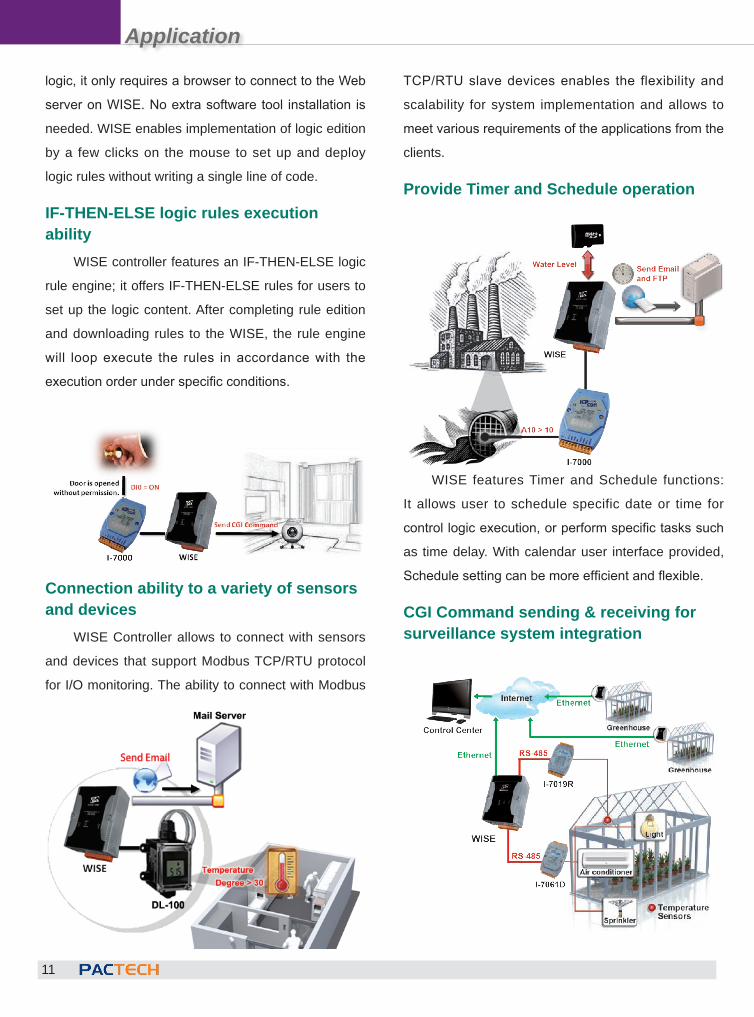
Connection ability to a variety of sensors and devices
WISE Controller allows to connect with sensors
and devices that support Modbus TCP/RTU protocol
for I/O monitoring. The ability to connect with Modbus
TCP/RTU slave devices enables the flexibility and
scalability for system implementation and allows to
meet various requirements of the applications from the
clients.
Provide Timer and Schedule operation
WISE features Timer and Schedule functions:
It allows user to schedule specific date or time for
control logic execution, or perform specific tasks such
as time delay. With calendar user interface provided,
Schedule setting can be more efficient and flexible.
CGI Command sending & receiving for surveillance system integration
Application
12
WISE supports full CGI command operations -
CGI command sending and CGI command receiving.
The CGI command sending action can be added to
the logic edition as part of logic control in response to
specific events. The CGI command receiving function
enables WISE to receive the CGI commands from
other network devices. The content of CGI command
received can be used in IF condition statements to
trigger the THEN/ELSE actions.
Real-time alarm notification via SSL EmailWISE supports SSL Email sending function
for real-time message notification operation. The
message sending action can be added to the logic
edition as part of logic control to provide real-time
message notification to the related personnel when an
event occurs.
Data Logger operationWith the microSD card, WISE provides Data
Logger function to real-time record the I/O channel
data of the controller and sends the data files
automatically by FTP to the control center for further
administration management or data analysis.
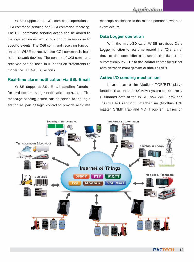
Active I/O sending mechanismIn addition to the Modbus TCP/RTU slave
function that enables SCADA system to poll the I/
O channel data of the WISE, now WISE provides
“Active I/O sending” mechanism (Modbus TCP
master, SNMP Trap and MQTT publish). Based on
Application
13
the “Active I/O sending”, WISE allows to send the
I/O channel data of the controller actively to SCADA/
IT system by event trigger (change of the I/O channel
data) or periodic cycle. This function will improve the
efficiency of the data communication between WISE
and SCADA/IT system.。
A variety of protocols supported for integration with SCADA/IT/IoT System
WISE supports various communication protocols
to perform real-time monitoring and control of the
controllers. The Modbus TCP/RTU protocol of WISE
allows sharing I/O channel and system data with
the SCADA system. WISE also support the SNMP,
CGI, FTP and MQTT protocols for easy integration
with the IT/MIS/MES/Facility management /Network
management system. The flexible integration ability
with the SCADA and IT system make WISE the most
cost-effective I/O controller in the IoT (Internet of
Things) applications
� Support Modbus TCP / RTU industrial protocol
� Support SNMP (Simple Network Management Protocol) network management protocol
� Support MQTT (MQ Telemetry Transport) protocol, to achieve the data linked to the concept of networking industries
� Support FTP Server / Client mechanisms to provide two-way data log file maintenance operations
� Support SSL / TLS Email, instant notification live state
� Support CGI (Common Gateway Interface) commands to send and receive, with network equipment (such as: IP Camera) complete interaction
� Support DDNS dynamic domain name system
Application � Building Automation � Factory Automation �Machine Automation � Facility Management � Facility Management � Environment Monitoring
WISE-5231 features easy-to-use, reliable and
multi-functions. It is designed to provide cost-effective
software and hardware solutions to meet various
requirements from the users and significantly reduce
the time and labor spent in the process of system
developments. For more information about WISE-
5231 please visit:
WISE-5231product catalogue:http://wise.icpdas.com/downloads/datasheet/WISE-52xx-EN.pdf
WISE-5231Website:http://wise.icpdas.com/news/WISE-5231/
ICP DAS Website:http://www.icpdas.com
Application
14
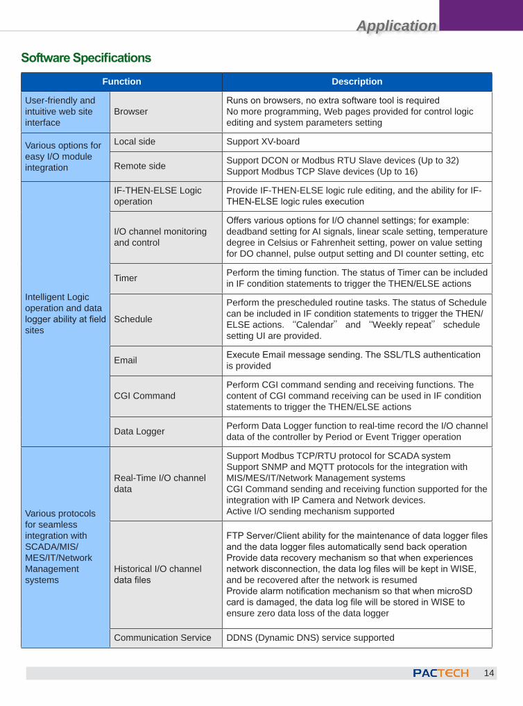
Software SpecificationsFunction Description
User-friendly and intuitive web site interface
BrowserRuns on browsers, no extra software tool is requiredNo more programming, Web pages provided for control logic editing and system parameters setting
Various options for easy I/O module integration
Local side Support XV-board
Remote side Support DCON or Modbus RTU Slave devices (Up to 32)Support Modbus TCP Slave devices (Up to 16)
Intelligent Logic operation and data logger ability at field sites
IF-THEN-ELSE Logic operation
Provide IF-THEN-ELSE logic rule editing, and the ability for IF-THEN-ELSE logic rules execution
I/O channel monitoring and control
Offers various options for I/O channel settings; for example: deadband setting for AI signals, linear scale setting, temperature degree in Celsius or Fahrenheit setting, power on value setting for DO channel, pulse output setting and DI counter setting, etc
Timer Perform the timing function. The status of Timer can be included in IF condition statements to trigger the THEN/ELSE actions
Schedule
Perform the prescheduled routine tasks. The status of Schedule can be included in IF condition statements to trigger the THEN/ELSE actions. “Calendar” and “Weekly repeat” schedule setting UI are provided.
Email Execute Email message sending. The SSL/TLS authentication is provided
CGI CommandPerform CGI command sending and receiving functions. The content of CGI command receiving can be used in IF condition statements to trigger the THEN/ELSE actions
Data Logger Perform Data Logger function to real-time record the I/O channel data of the controller by Period or Event Trigger operation
Various protocols for seamless integration with SCADA/MIS/ MES/IT/Network Management systems
Real-Time I/O channel data
Support Modbus TCP/RTU protocol for SCADA systemSupport SNMP and MQTT protocols for the integration with MIS/MES/IT/Network Management systemsCGI Command sending and receiving function supported for the integration with IP Camera and Network devices.Active I/O sending mechanism supported
Historical I/O channel data files
FTP Server/Client ability for the maintenance of data logger files and the data logger files automatically send back operationProvide data recovery mechanism so that when experiences network disconnection, the data log files will be kept in WISE, and be recovered after the network is resumedProvide alarm notification mechanism so that when microSD card is damaged, the data log file will be stored in WISE to ensure zero data loss of the data logger
Communication Service DDNS (Dynamic DNS) service supported
Application
15
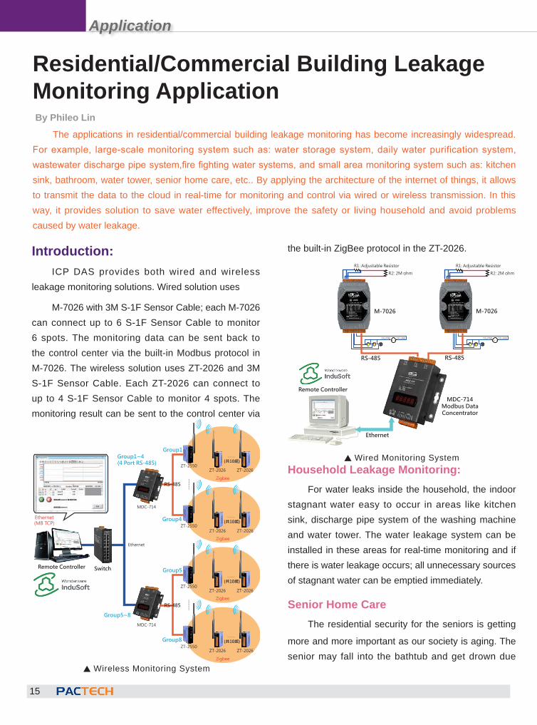
Introduction:ICP DAS provides both wired and wireless
leakage monitoring solutions. Wired solution uses
M-7026 with 3M S-1F Sensor Cable; each M-7026 can connect up to 6 S-1F Sensor Cable to monitor 6 spots. The monitoring data can be sent back to the control center via the built-in Modbus protocol in M-7026. The wireless solution uses ZT-2026 and 3M S-1F Sensor Cable. Each ZT-2026 can connect to up to 4 S-1F Sensor Cable to monitor 4 spots. The monitoring result can be sent to the control center via
the built-in ZigBee protocol in the ZT-2026.
Household Leakage Monitoring:For water leaks inside the household, the indoor
stagnant water easy to occur in areas like kitchen sink, discharge pipe system of the washing machine and water tower. The water leakage system can be installed in these areas for real-time monitoring and if there is water leakage occurs; all unnecessary sources of stagnant water can be emptied immediately.
Senior Home CareThe residential security for the seniors is getting
more and more important as our society is aging. The senior may fall into the bathtub and get drown due
Residential/Commercial Building Leakage Monitoring ApplicationBy Phileo Lin
The applications in residential/commercial building leakage monitoring has become increasingly widespread. For example, large-scale monitoring system such as: water storage system, daily water purification system, wastewater discharge pipe system,fire fighting water systems, and small area monitoring system such as: kitchen sink, bathroom, water tower, senior home care, etc.. By applying the architecture of the internet of things, it allows to transmit the data to the cloud in real-time for monitoring and control via wired or wireless transmission. In this way, it provides solution to save water effectively, improve the safety or living household and avoid problems caused by water leakage.
⋯⋯
Remote Controller
Ethernet(MB TCP)
Switch
Group1~4(4 Port RS-485)
Ethernet
Group5~8
MDC-714
Group1
Group8
ZT-2550ZT-2026
Zigbee
MDC-714
ZT-2550
ZT-2026
Group5
Group4
ZT-2550
ZT-2550
……
……
……
(共10組)
RS-485
RS-485
⋯⋯
ZT-2026
Zigbee
ZT-2026
(共10組)
⋯⋯
ZT-2026
Zigbee
ZT-2026
(共10組)
⋯⋯
ZT-2026
Zigbee
ZT-2026
(共10組)
S Wireless Monitoring System
R1: Adjustable Resistor
R2: 2M ohm
+-DO_GNDDO_PWR
R1: Adjustable Resistor
R2: 2M ohm
+-DO_GNDDO_PWR
Remote Controller
MDC-714Modbus DataConcentrator
RS-485
M-7026 M-7026
Ethernet
RS-485
S Wired Monitoring System
Application
16
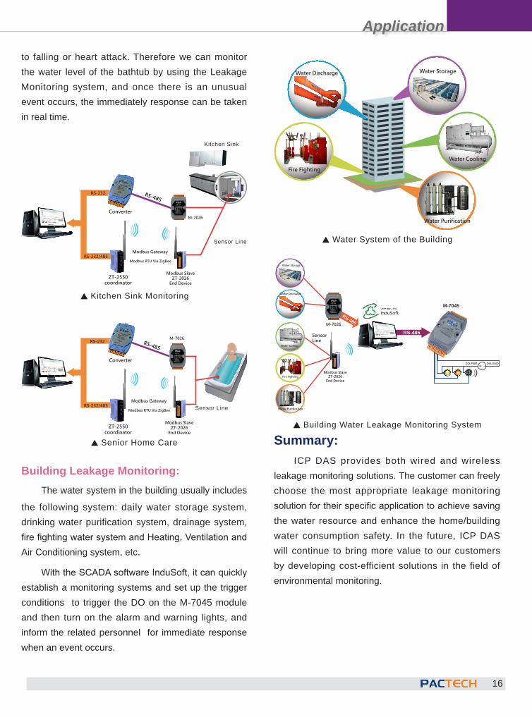
to falling or heart attack. Therefore we can monitor the water level of the bathtub by using the Leakage Monitoring system, and once there is an unusual event occurs, the immediately response can be taken in real time.
Building Leakage Monitoring:The water system in the building usually includes
the following system: daily water storage system, drinking water purification system, drainage system, fire fighting water system and Heating, Ventilation and Air Conditioning system, etc.
With the SCADA software InduSoft, it can quickly establish a monitoring systems and set up the trigger conditions to trigger the DO on the M-7045 module and then turn on the alarm and warning lights, and inform the related personnel for immediate response when an event occurs.
Summary:ICP DAS provides both wired and wireless
leakage monitoring solutions. The customer can freely choose the most appropriate leakage monitoring solution for their specific application to achieve saving the water resource and enhance the home/building water consumption safety. In the future, ICP DAS will continue to bring more value to our customers by developing cost-efficient solutions in the field of environmental monitoring.
Water Storage
Water Cooling
Water Discharge
Fire Fighting
Water Purification
S Water System of the Building
S Building Water Leakage Monitoring System
M-7045
RS-485
Water Storage
Water Colling
Water Discharge
Fire Fighting
Water Purification
Sensor Line
Modbus SlaveZT-2026
End Device
M-7026
DO_GNDDO_PWR +-
RS-485
S Kitchen Sink Monitoring
流理臺
檢知線
RS-485
ZT-2550coordinator
Modbus SlaveZT-2026
End Device
Modbus RTU Via ZigBee
Modbus Gateway
ConverterM-7026
RS-232
RS-232/485
Kitchen Sink
Sensor Line
S Senior Home Care
檢知線
RS-485
ZT-2550coordinator
Modbus SlaveZT-2026
End Device
Modbus RTU Via ZigBee
Modbus Gateway
Converter
M-7026RS-232
RS-232/485 Sensor Line

Application
17
DescriptionThis application is to implement lighting control
system for sickrooms in a local hospital, we will
transform traditional control system to smart building
automation control system. The following devices are
the major devices used in the applications:
SC-4104-W1
The SC-4104-W1 is perfect to be used in Fan Coil
Unit and indoor lighting control. It features built-in logic
for quickly switch to different scenarios. A variety of
scenarios interlocking reactions are provided for users
to quickly switch to desired fan speed and lighting
intensity.
Lighting and Air Conditioning Management System in HospitalBy Austin Lin
ICP DAS TouchPAD features all in one functions such as: quick deployment, rapid integration, easy
maintenance and display. It cut the cost of PLC and HMI yet provides similar or even more convenient features. By
using ICP DAS TouchPAD (TPD) to control the devices and function as communication interface; TPD can work
as a controller equipped with display function which add more values and upgrade the competitiveness in project
implementation.
SC-4104-W1 module provides three types of built-in control logic: each type provides three interlocking control
functions. The user can freely switch in functions to quickly build and design most appropriate applications.
IntroductionIn most temperature control applications, usually
it uses one master control panel to work with more
than one control boxes. However the master control
panel can only communicate with the control boxes
connected under its architecture. Each time when
adding new sensors or modules to the system for
new requirement, it is required to design a new
architecture. However, for TPD-283U, our driver allows
to add new modules freely at any time, no matter
via communication interfaces such as RS-485 serial
communication device or Ethernet, which provides a
friendly and easy solution to the maintenance staff.
Application
18
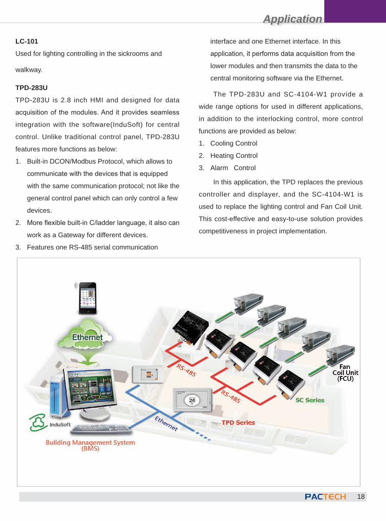
LC-101
Used for lighting controlling in the sickrooms and
walkway.
TPD-283U
TPD-283U is 2.8 inch HMI and designed for data
acquisition of the modules. And it provides seamless
integration with the software(InduSoft) for central
control. Unlike traditional control panel, TPD-283U
features more functions as below:
1. Built-in DCON/Modbus Protocol, which allows to
communicate with the devices that is equipped
with the same communication protocol; not like the
general control panel which can only control a few
devices.
2. More flexible built-in C/ladder language, it also can
work as a Gateway for different devices.
3. Features one RS-485 serial communication
interface and one Ethernet interface. In this
application, it performs data acquisition from the
lower modules and then transmits the data to the
central monitoring software via the Ethernet.
The TPD-283U and SC-4104-W1 provide a
wide range options for used in different applications,
in addition to the interlocking control, more control
functions are provided as below:
1. Cooling Control
2. Heating Control
3. Alarm Control
In this application, the TPD replaces the previous
controller and displayer, and the SC-4104-W1 is
used to replace the lighting control and Fan Coil Unit.
This cost-effective and easy-to-use solution provides
competitiveness in project implementation.
Application
19
PAC in Railway Signaling ApplicationBy Cony Yu
The Railway Signaling system is a series of chain control system. If one device is failed; a series of back-
end devices may also be failed. It caused the difficulty for the maintenance personnel to trouble shooting; they
can only check step by step to verify which operation is failed based on the final failure result; the maintenance
personnel is easy to be confused and hard to find the source of the trouble.
By using the railway signaling monitoring & control system, the signal can be effectively operated, and the
management can be centralized and can easily analyze and track the causes of failure which makes it easy to
quickly rule out or trace the problem sources so that any device failure can be detected in real time. The safety of
railway operations will be enhanced, train punctuality will be improved and the maintenance work will be easier to
achieve a reliable and efficient railway signaling management system.
For railway signaling, as the
increasing of the high-speed train
and train service frequency, and
external factors such as climates
and night time driving risk, the
ra i lway s igna l ing system has
become more and more important.
T h e p u r p o s e f o r r a i l w a y
signal ing monitoring & control
system is aimed to increase the
reliability and efficiency of railway
signaling operations. By using
network transmission and user-
friendly graphic control interfaces,
it is easy to perform operations of
the hardware or software devices
for railway signaling management,
and then the information can be
collected for further data analysis,
furthermore, makes i t easy to
quickly rule out or trace the problem
sources so that any device failure
can be detected in real time. The
safety of railway operations will be
enhanced, train punctuality will be
improved and the maintenance work
will be easier to achieve a reliable
and eff icient rai lway signal ing
management system.
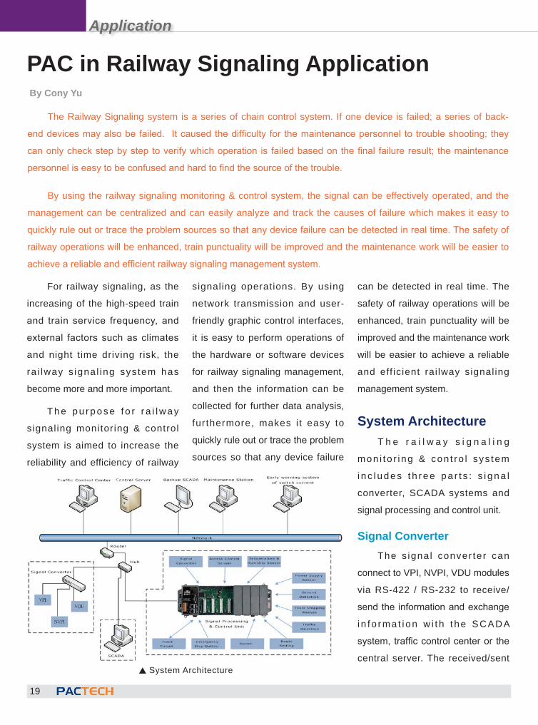
System ArchitectureT h e r a i l w a y s i g n a l i n g
mon i to r i ng & con t ro l sys tem
i n c l u d e s t h r e e p a r t s : s i g n a l
converter, SCADA systems and
signal processing and control unit.
Signal ConverterThe s igna l conver ter can
connect to VPI, NVPI, VDU modules
via RS-422 / RS-232 to receive/
send the information and exchange
i n f o rma t i on w i t h t he SCADA
system, traffic control center or the
central server. The received/sent S System Architecture
Application
20
information including the following: CTC information,
VDU information, PIDS communication information,
station information before (or after), receiving (or
sending), etc.. The information that the SCADA
system receiving before/after or sending before/ after
will be decoded and then the data (or processed data)
can be displayed or recorded.
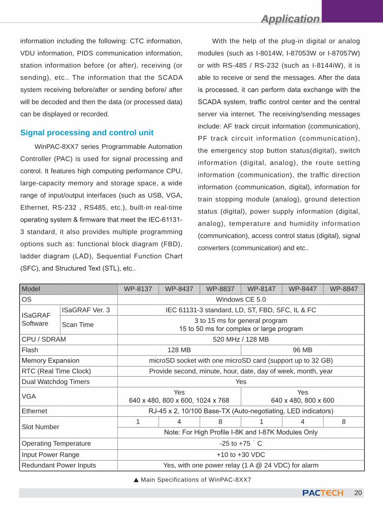
Signal processing and control unitWinPAC-8XX7 series Programmable Automation
Controller (PAC) is used for signal processing and
control. It features high computing performance CPU,
large-capacity memory and storage space, a wide
range of input/output interfaces (such as USB, VGA,
Ethernet, RS-232 , RS485, etc.), built-in real-time
operating system & firmware that meet the IEC-61131-
3 standard, it also provides multiple programming
options such as: functional block diagram (FBD),
ladder diagram (LAD), Sequential Function Chart
(SFC), and Structured Text (STL), etc..
Model WP-8137 WP-8437 WP-8837 WP-8147 WP-8447 WP-8847OS Windows CE 5.0
ISaGRAFSoftware
ISaGRAF Ver. 3 IEC 61131-3 standard, LD, ST, FBD, SFC, IL & FC
Scan Time 3 to 15 ms for general program15 to 50 ms for complex or large program
CPU / SDRAM 520 MHz / 128 MBFlash 128 MB 96 MBMemory Expansion microSD socket with one microSD card (support up to 32 GB)RTC (Real Time Clock) Provide second, minute, hour, date, day of week, month, yearDual Watchdog Timers Yes
VGA Yes640 x 480, 800 x 600, 1024 x 768
Yes640 x 480, 800 x 600
Ethernet RJ-45 x 2, 10/100 Base-TX (Auto-negotiating, LED indicators)
Slot Number1 4 8 1 4 8
Note: For High Profile I-8K and I-87K Modules OnlyOperating Temperature -25 to +75 ° CInput Power Range +10 to +30 VDCRedundant Power Inputs Yes, with one power relay (1 A @ 24 VDC) for alarm
S Main Specifications of WinPAC-8XX7
With the help of the plug-in digital or analog
modules (such as I-8014W, I-87053W or I-87057W)
or with RS-485 / RS-232 (such as I-8144iW), it is
able to receive or send the messages. After the data
is processed, it can perform data exchange with the
SCADA system, traffic control center and the central
server via internet. The receiving/sending messages
include: AF track circuit information (communication),
PF track circuit information (communication),
the emergency stop button status(digital), switch
information (digital, analog), the route setting
information (communication), the traffic direction
information (communication, digital), information for
train stopping module (analog), ground detection
status (digital), power supply information (digital,
analog), temperature and humidity information
(communication), access control status (digital), signal
converters (communication) and etc..
Application
21
SCADA SystemThe SCADA system adopts intuitive graphic
control interface, the information of signal converter
or the signal processing and control unit can be
displayed hierarchically on pages. The main page
includes: real-time data, accumulated data, and
charts/data analysis. The sub-pages includes the
following control interfaces: alarm management
(real-time and historical data inquiry), statistics &
analysis reports, parameter settings for critical values,
database management, settings or modification for
system operation parameters and replay of track
operations. With access control mechanism, the
administrators or general operators can access the
control system in the control room or via remote
network.
The real-time information page displays the
route in diagram and shows the connection status of
the stations in real time. The monitoring page shows
the real-time information of each monitoring point in
the station, and shows the speed code of each track
circuit, working current of the track circuit and the
reverse current value of the switch in the route map.
On the accumulated data page, it shows the error
message log and the time chart of working current
of each track circuit. The replay of track operations
is also an important function to be displayed. When
the track operation is abnormal, after performing
troubleshooting operations, the replay of track
operations can be used to verify the source problem
that result in abnormal operations, and then improve
the system or clarify the responsibility in relation
accordingly.
The replay function of Track operation is
designed to monitoring the system. It can be replayed
at 0.5 or 2 times speed which makes it more efficient
when retrieval of a specific event is required.
The data analysis chart page can be used to
perform warning analysis to avoid failure occurring.
The following figure shows an example of switch
motor of railroad switch; the switch drive motor
includes forward and reverse modes. The warning
analysis can be done by comparing the motor data
provided by the manufacture before the installation
(including the voltage, current and power graph of the
forward/ reverse motor) with the real detected data
measured after installing the railroad switch. Based on
thread hold criteria provided by the customer (including
the time to start the railroad switch till reach the fixed
position and the peak measure value after starting
the switch.) When the criteria of the thread hold is
exceeded; it will send out warning message to remind
the related personnel for maintenance or replacement
of the devices.
SummaryTo implement a track signal monitoring & control
system, the system integrator who plan and build the
system usually need to invest a huge amount in initial
investment; and the cost for mid-term & long-term
maintenance is also quite impressive. In recent years,
with the hard-working of ICP DAS and its cooperate
system integrator, ICP DAS has accumulated
experience in this field. We believes that more cost-
effective applications for track signal system will be
developed in the near future.
Application
22
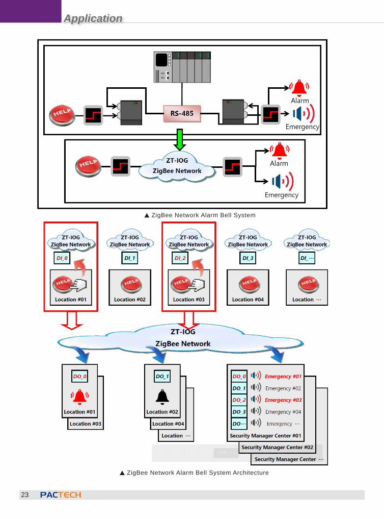
ZigBee Application - Emergency Bell Alarm System
Emergency bell alarm system is often used in MRT, buildings, schools, hospitals and other public places for
security management. When an accident occurs, one can press the alarm bell to immediately notify the related
personnel, at the same time, the security control center will be informed the event's location and send the staff to
take immediate actions right away.
DescriptionUsing the campus security
management as an example, in a
traditional alarm bell system, the
alarm bell is installed in a restroom
entrance and is only l inked to
a buzzer bell for regional alarm
notification. But in such way, when
encounters an emergency, the staffs
of the security center can not be
notified immediately and efficiently.
To reply the emergency state to the
host of the security control center,
users must pay higher costs in
wiring deployment to transmit the
messages from multiple locations to
the security control center; if these
locations are widespread or across
different buildings, the costs are
often quite expensive.
ZT-IOG System is Perfect for Emergency Bell Alarm System
According to above application
statement, in order to solve the
difficulty and high cost problems
of wiring deployment, ICP DAS
prov ides the Z igBee wire less
solution. The ZT-IOG system can
automat ical ly update the DIO
channel status to the message
center (ZigBee Coordinator) via the
wireless communication, and then
the message center will synchronize
all DO channel status of the ZT-IOG
network. This synchronization of
changing DO states may function as
the "emergency alert" to trigger the
alarm bell.
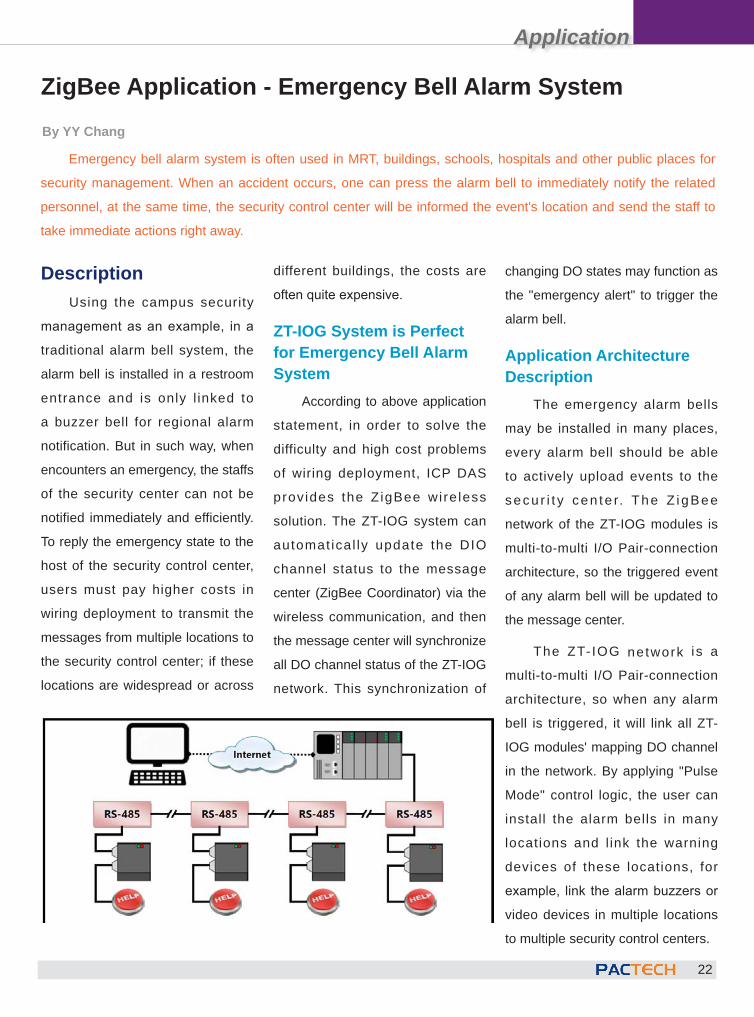
Application Architecture Description
The emergency alarm bells
may be installed in many places,
every alarm bell should be able
to actively upload events to the
secu r i t y cen te r. The Z igBee
network of the ZT-IOG modules is
multi-to-multi I/O Pair-connection
architecture, so the triggered event
of any alarm bell will be updated to
the message center.
The ZT- IOG network is a
multi-to-multi I/O Pair-connection
architecture, so when any alarm
bell is triggered, it will link all ZT-
IOG modules' mapping DO channel
in the network. By applying "Pulse
Mode" control logic, the user can
install the alarm bells in many
locations and l ink the warning
devices of these locations, for
example, link the alarm buzzers or
video devices in multiple locations
to multiple security control centers.
By YY Chang
Application
23
S ZigBee Network Alarm Bell System
S ZigBee Network Alarm Bell System Architecture
Application
24
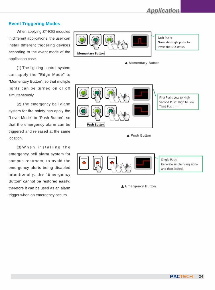
S Momentary Button
Event Triggering ModesWhen applying ZT-IOG modules
in different applications, the user can
install different triggering devices
according to the event mode of the
application case.
(1) The lighting control system
can apply the "Edge Mode" to
"Momentary Button", so that multiple
l ights can be turned on or off
simultaneously.
(2) The emergency bell alarm
system for fire safety can apply the
"Level Mode" to "Push Button", so
that the emergency alarm can be
triggered and released at the same
location.
(3) W h e n i n s t a l l i n g t h e
emergency bell alarm system for
campus restroom, to avoid the
emergency alerts being disabled
in tent iona l ly ; the "Emergency
Button" cannot be restored easily;
therefore it can be used as an alarm
trigger when an emergency occurs.
S Push Button
S Emergency Button
Application
25
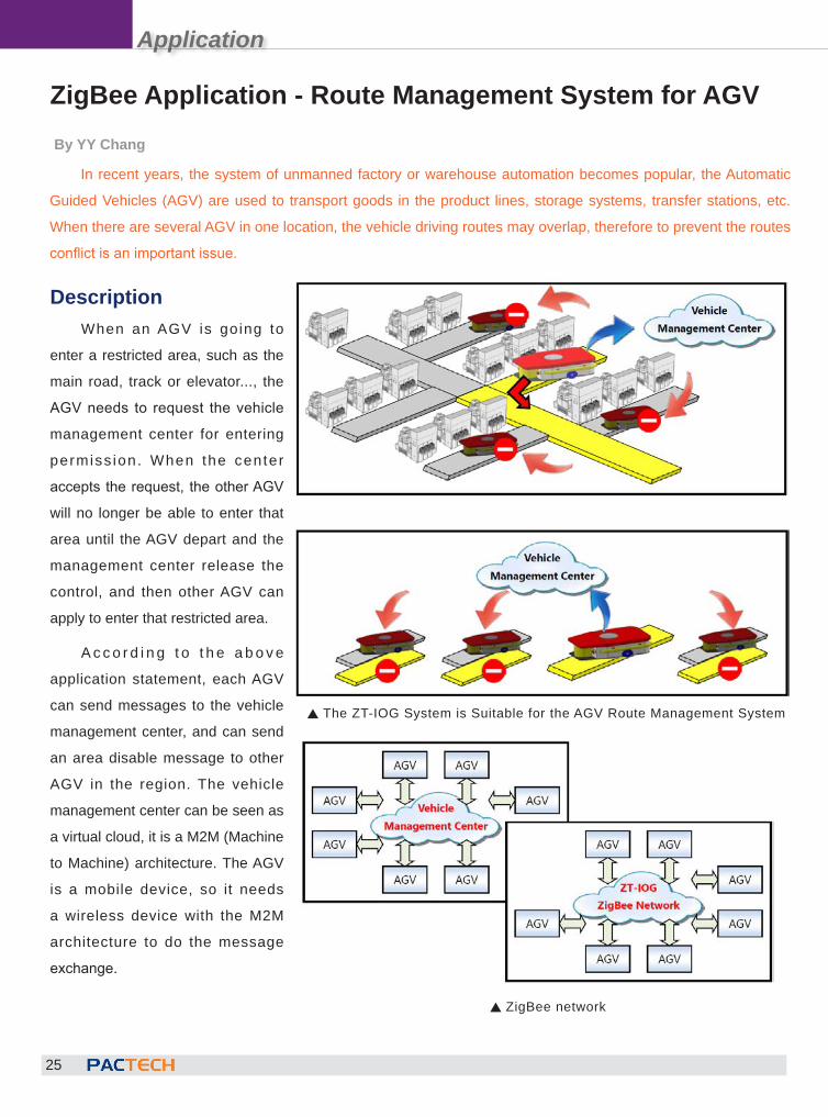
ZigBee Application - Route Management System for AGVBy YY Chang
In recent years, the system of unmanned factory or warehouse automation becomes popular, the Automatic
Guided Vehicles (AGV) are used to transport goods in the product lines, storage systems, transfer stations, etc.
When there are several AGV in one location, the vehicle driving routes may overlap, therefore to prevent the routes
conflict is an important issue.
DescriptionWhen an AGV is going to
enter a restricted area, such as the
main road, track or elevator..., the
AGV needs to request the vehicle
management center for entering
permiss ion. When the center
accepts the request, the other AGV
will no longer be able to enter that
area until the AGV depart and the
management center release the
control, and then other AGV can
apply to enter that restricted area.
A c c o r d i n g t o t h e a b o v e
application statement, each AGV
can send messages to the vehicle
management center, and can send
an area disable message to other
AGV in the region. The vehicle
management center can be seen as
a virtual cloud, it is a M2M (Machine
to Machine) architecture. The AGV
is a mobile device, so it needs
a wireless device with the M2M
architecture to do the message
exchange.
S The ZT-IOG System is Suitable for the AGV Route Management System
S ZigBee network
Application
26
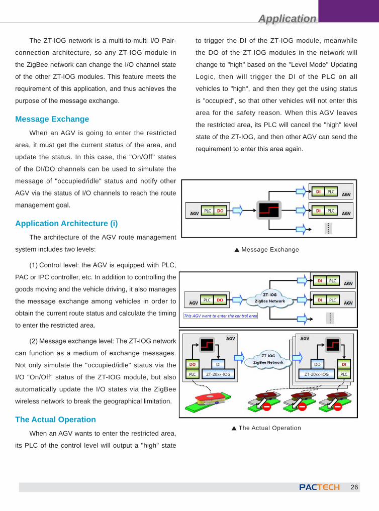
The ZT-IOG network is a multi-to-multi I/O Pair-
connection architecture, so any ZT-IOG module in
the ZigBee network can change the I/O channel state
of the other ZT-IOG modules. This feature meets the
requirement of this application, and thus achieves the
purpose of the message exchange.
Message ExchangeWhen an AGV is going to enter the restricted
area, it must get the current status of the area, and
update the status. In this case, the "On/Off" states
of the DI/DO channels can be used to simulate the
message of "occupied/idle" status and notify other
AGV via the status of I/O channels to reach the route
management goal.
Application Architecture (i)The architecture of the AGV route management
system includes two levels:
(1) Control level: the AGV is equipped with PLC,
PAC or IPC controller, etc. In addition to controlling the
goods moving and the vehicle driving, it also manages
the message exchange among vehicles in order to
obtain the current route status and calculate the timing
to enter the restricted area.
(2) Message exchange level: The ZT-IOG network
can function as a medium of exchange messages.
Not only simulate the "occupied/idle" status via the
I/O "On/Off" status of the ZT-IOG module, but also
automatically update the I/O states via the ZigBee
wireless network to break the geographical limitation.
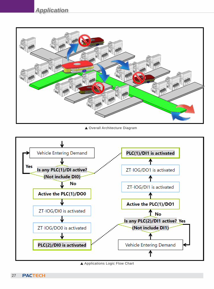
The Actual OperationWhen an AGV wants to enter the restricted area,
its PLC of the control level will output a "high" state
to trigger the DI of the ZT-IOG module, meanwhile
the DO of the ZT-IOG modules in the network will
change to "high" based on the "Level Mode" Updating
Logic, then will trigger the DI of the PLC on all
vehicles to "high", and then they get the using status
is "occupied", so that other vehicles will not enter this
area for the safety reason. When this AGV leaves
the restricted area, its PLC will cancel the "high" level
state of the ZT-IOG, and then other AGV can send the
requirement to enter this area again.
S The Actual Operation
S Message Exchange
Application
27
S Applications Logic Flow Chart
S Overall Architecture Diagram
Application
28
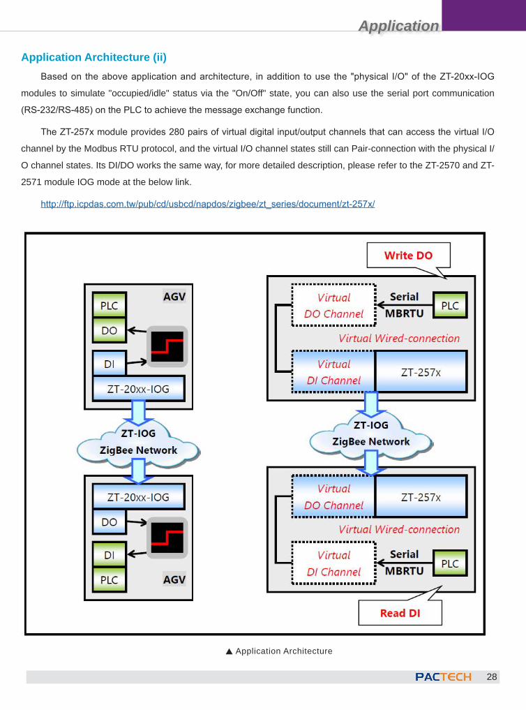
Application Architecture (ii)Based on the above application and architecture, in addition to use the "physical I/O" of the ZT-20xx-IOG
modules to simulate "occupied/idle" status via the "On/Off" state, you can also use the serial port communication
(RS-232/RS-485) on the PLC to achieve the message exchange function.
The ZT-257x module provides 280 pairs of virtual digital input/output channels that can access the virtual I/O
channel by the Modbus RTU protocol, and the virtual I/O channel states still can Pair-connection with the physical I/
O channel states. Its DI/DO works the same way, for more detailed description, please refer to the ZT-2570 and ZT-
2571 module IOG mode at the below link.
http://ftp.icpdas.com.tw/pub/cd/usbcd/napdos/zigbee/zt_series/document/zt-257x/
S Application Architecture


![OCampus] IoT architecture › _media › neocampus-iot-architecture_sep17.pdfUsing Mosquitto v1.4.9 + auth_plugin → MQTT v3.1.1 note: AMQP emulates MQTT protocol but without user](https://static.documents.pub/doc/80x56/5f0d88ab7e708231d43ad580/ocampus-iot-architecture-a-media-a-neocampus-iot-architecturesep17pdf-using.jpg)


