Page 1
CONTENTS
Page
Outline of Incident .................................................. 1
Authority to Conduct Investigation ................................... 2
Persons Interviewed .................................................. 3
Basis of Investigation ............................................... 5
Particulars of Ship's Heavy Lift Operations
Cargo Handling Gear ......................................... 6
Pontoon Stabilizers ......................................... 8
Stability Data ............................................. 10
Sequence of Events .................................................. 11
Observations ........................................................ 18
Conclusions ......................................................... 21
Appendices ....................................................... 24-37
Particulars of Ship ......................................... Appendix 1
General Arrangement of Ship ................................. Appendix 2
Stability Terminology ....................................... Appendix 3
Stability Analysis .......................................... Appendix 4
Summary of Results of Examination and Tests
by Unisearch Ltd, University of New South Wales..............Appendix 5
Page 2
- 1 -
OUTLINE OF INCIDENT
Shortly before noon on Thursday 14 August 1986 the Netherlands Antilles flag
heavy lift cargo ship 'GABRIELLA' capsized and sank alongside No. 2 Products
Berth in Port Kembla harbour New South Wales.
The ship capsized and sank on its side very rapidly while discharging a lift
of 237.95 tonnes.
Two marine surveyors, Mr. David Brooke-Sm
and Mr. William Martin of Bureau Veritas,
ingith of Lloyds Register of Shipp
were unable to escape from the
accommodation area of the ship and lost their lives. Apart from minor
injuries to several persons there were no other casualties.
The ship was declared a constructive total loss. Subsequently both masts and
the accommodation deck houses were cut off and the hull was re-floated upside
down. It was towed out and sunk at sea on 10 December 1986 in Latitude
34° 34'.5 South, Longitude 151° 30'.8 East, about 29 nautical miles east of
Port Kembla in a depth of water of about 2000 metres.
Page 3
- 2 -
AUTHORITY TO CONDUCT INVESTIGATION
On 14 August 1986 John Michael Quinlan, Principal Marine Surveyor for New
South Wales in the Federal Department of Transport, was appointed under
Section 377A of the Navigation Act 1912 to make a Preliminary Investigation
into the circumstances of the capsize of the Netherlands Antilles registered
ship 'GABRIELLA' (call sign PJTQ) in Port Kembla harbour on 14 August 1986.
Page 4
- 3 -
PERSONS INTERVIEWED
The following crew members were interviewed between the 15-18 August 1986
before their return to the Netherlands:
Peter BOMMELS
Gerrit in 't VELT
Robert BOSKALJON
Alfred Marinus van AARTSEN
Gerard Koenraad SCHOLTEN
Pedro Tavares MONTEIRO
Joao Francisco RAMOS
Paul KUIKEN
Master
Chief Engineer
Chief Officer
Second Officer
Second Engineer
Able Seaman
Able Seaman
Ordinary Seaman
Between 15 August and 29 January 1987 the following other persons were
interviewed:
Alan Henry JONES Foreman Stevedore, Port Waratah Stevedoring
Company Limited, Port Kembla.
Arnold Frederik van der HEUL Operations Manager, Kahn Shipping Rotterdam
(operators of the ship).
Gustaaf Leendert KEESEN Marine Surveyor, Port Kembla.
Grahame Dennis AULBURY Operations Transport Manager, Brambles Heavy
Haulage Division, Sydney.
Derek SIM
Paul James MICHELL
Stevedoring Superintendent, Port Waratah
Stevedoring Company Limited, Port Kembla.
Leading hand boilermaker, construction
department Australian Iron and Steel, Port
Kembla.
Page 5
Barry FLANAGAN
Donald Barry MCGREGOR
Barry Allan EDWARDS
Kenneth Thomas MCBRIDE
Rory SLADE
-4-
Proprietor, Illawarra Wire Ropes, Port
Kembla.
Waterside worker. Port Kembla.
Waterside worker. Port Kembla.
Waterside worker. Port Kembla.
Waterside worker. Port Kembla.
Page 6
- 5-
BASIS OF INVESTIGATION
The scene of the incident was visited early on the morning of 15 August 1986
and the ship was observed lying on its port side on the harbour bottom
alongside No. 2 Products Berth at Port Kembla. The heavy lift involved was
lying where it fell onto a platform trailer on the wharf. Notes were made at
the scene.
About an hour after the incident, Senior Constable Pieter Strik of the New
South Wales Police Force Scientific Investigation Section took a series of
photographs and recovered some pieces of broken wire strands on and near the
platform trailer. Senior Constable Strik was investigating the incident as
part of the routine police response.
During the salvage operation, sections of the wire runner on the forward
derrick were recovered from the harbour. These sections of wire rope,
together with one of the broken strands found by Senior Constable Strik, were
submitted to Unisearch Limited at the University of New South Wales for
scientific examination and tests. A summary of the examination and test
reports is set out in Appendix 5.
Information about the ship was also provided by the Netherlands
Scheepvaartinspectie (Shipping Inspectorate) and an inspection of cargo
operations on the sister ship 'FAIRLOAD' was carried out at Brisbane on 16
September 1986.
The following report is based on the above information, interviews,
inspections and tests and on copies of the ship's documents and records
supplied by the operators of the ship, Kahn Scheepvaart (Kahn Shipping) B.V.
of Rotterdam.
In view of the technical nature of the operation and the circumstances leading
up to the capsize, this report is by necessity complex in parts. The majority
of supporting material of this type is included in the Appendices, however
some data of a technical nature has unavoidably been included in the narrative
sections of the report.
Page 7
- 6 -
PARTICULARS OF SHIP'S HEAVY LIFT OPERATIONS
CARGO HANDLING GEAR
'GABRIELLA' was fitted with two derricks serving its single cargo hold (see
Appendix 2). Each derrick had a safe working load (SWL) of 160 tons at an
angle to the horizontal of 47°. At an angle to the horizontal of 25° the SWL
was 125 tons each. No SWL was assigned for derrick angles below 25° to the
horizontal.
Certificate of Attestation No. 95/78 issued on 27 April 1978 by the Chief
Representative of Bureau Veritas in the Netherlands declared that the ship was
suitable to load and discharge weights up to 320 tons using the two derricks
in tandem, provided the load on each derrick was no more than 160 tons.
However, the lifting yoke supplied for use with the derricks in tandem had a
SWL of only 240 tons, which together with the mass of the yoke of 30 tons
indicated a maximum load in practice of 270 tons, when using the lifting yoke.
The lifting yoke consisted of two parallel beams 17.5 metres in length and
11.5 tons each supported at their ends by short transverse connections
suspended from ramshorn type main lifting hooks. The transverse connections
(2 tons each) fitted into inverted 'U' shape recesses in the ends of the
parallel beams and after assembly on the ship were held in place by lightly
welded plates. These plates were not designed to withstand any loads other
than random light loads during assembly and deployment of the yoke prior to
lifting. Assembly of the yoke was completed by fitting two transverse
slinging beams across the parallel beams. The slinging beams were held in
place by guides and their own mass (1.5 tons each).
A copy of the ship's Register of Cargo Gear and Certificates supplied by the
operators, Kahn Shipping, indicated that the cargo gear was tested and
periodically examined in accordance with laws in force in the Netherlands.
The last quadrennial thorough examination of the forward derrick and
associated gear was carried out at Rotterdam in June 1983 by A. Kwint B.V.
Authorised Ship Riggers and Testers and noted by the Netherlands Inspectie Van
de Havenarbeid (Dock Labour Inspectorate - government authority administering
laws on ships cargo gear). The last quadrennial thorough examination of the
Page 8
- 7 -
aft derrick and associated gear was carried out in February 1982 by I.
Roodenburg B.V. an engineering works at Krimpen a/d IJssel in the
Netherlands. A visual inspection of all the cargo gear was made on 7 April
1986 by Inspectie van de Havenarbeid. The gear was found in good condition
and an exemption from quadrennial thorough examination of the aft derrick and
associated gear was granted until 1 March 1987 to enable the owners to
synchronise surveys.
The master stated at interview that he kept the Register of Cargo Gear and
that all entries were up to date. He also stated that he carried out the last
annual examination of cargo gear at Higashi Harima Japan about 8 July 1986 and
found it in good condition.
That examination, he said, included all the derrick runners and topping
lift/slewing wire ropes. He went on to say that the wire ropes were checked
"all the time" when discharging at Port Kembla and he had not noticed any
broken strand wires. He last saw the Cargo Gear Register lying on top of the
safe in his cabin.
The word 'tons' appearing in the cargo gear documents is not specifically
defined except on one certificate relating to the construction of the derricks
where the maximum compression load is shown in 'tons of 1000 kgs'. The
derrick test certificates, issued on both Dutch and British statutory forms
show identical SWLs in tons and it is assumed that these are tons of 2240
British Imperial pounds. However, the element of doubt on the matter is not
significant in this investigation.
Documents provided by the owners and statements made by the master indicate
that cargo gear testing and examination requirements of the Australian
Navigation (Loading and Unloading-Safety Measures) Regulations were complied
with at the time of the casualty. However, see Observations page 18, relating
to the examination of wire ropes.
Page 9
- 8 -
PONTOON STABILIZERS
'GABRIELLA', like her sister ship 'FAIRLOAD' and a number of other heavy lift
ships operated by Kahn Scheepvaart, used pontoon stabilizers to improve the
stability of the ship by increasing the initial metacentric height (GM), thus
enabling use of the ship's own cargo gear for heavy cargoes.
'GABRIELLA' was provided with two pontoons. A set of curves in the ship's
stability book gave the height of the metacentre (M) above the keel (K),
referred to as KM, for various displacements using either one or two or no
pontoons. For example, immediately before capsize the ship's displacement was
2767 tonnes, two pontoons were deployed and the KM from the appropriate curve
was 10.16 metres. Without pontoons, the KM would have been 6.60 metres, a
very significant reduction that would have resulted in a negative GM, the
height of the ship's centre of gravity above the keel (KG) at that time being
7.58 metres. The terms GM, KM etc., are illustrated in Figures A, B, C in
Appendix 3.
The principle of the system is to float a pontoon alongside on the side of the
ship opposite to the'side over which heavy cargo is to be handled. By opening
bottom valves in a flooding chamber the pontoon is allowed to sink until it
floats on buoyancy chambers at a draught of about one metre, which is half the
depth of the pontoon. The valves are then closed and the pontoon rigidly
secured to the ship's side by special heavy duty locking and lashing
arrangements. The securing arrangements were designed to withstand the
stresses imposed when the pontoon is fully immersed or fully emerged, provided
list and trim either way do not exceed 4° and 2° respectively and provided
water flow parallel to the ship does not exceed 6 knots.
Page 10
- 9 -
In effect, a secured pontoon is part of the ship's hull. It increases the
area of the waterplane. The height of the transverse metacentre (M) above the
centre of buoyancy (B) is directly proportional to the transverse moment of
inertia of the waterplane so that the pontoon increases BM and hence KM and
GM.
If the ship listed so that a pontoon began to immerse or emerge, thus
decreasing the pontoon waterplane area, the ship would start to lose its
increased GM. It was vital therefore that the list was controlled within
limits to avoid this eventuality. The ship was fitted with anti-heeling tanks
on each side, to or from which water ballast was pumped or transferred to
control the list and maintain the pontoon waterplane area, while heavy cargo
was being lifted over the ship's side. 'GABRIELLA' was also fitted with
permanent cast iron ballast in the port lower anti-heeling tank so that heavy
cargoes were normally handled over the starboard side, with the stabilizer
pontoons being fitted on the port side. Detailed instructions on the use of
the pontoons and controlling the list were set out in a ship's manual -
"Loading and Discharging of Heavy Cargoes".
It must be emphasized that the stabilizer pontoons were not counterweights and
that their function was solely to increase the ship's initial stability or
metacentric height (GM). The pontoons and their securing arrangements were
not designed to provide buoyancy, or to withstand capsizing forces in the
event of a sudden loss of a load from the derrick when swung outboard.
Page 11
- 10 -
STABILITY DATA
The Netherlands Shipping Inspectorate advised that it approved the stability
data for 'GABRIELLA' in 1974. Kahn Scheepvaart supplied copies of the data
for this investigation. Stability calculations for heavy cargoes are pre-
planned for various stages of the operations on a computer in the office of
Kahn Scheepvaart in Rotterdam. The operations manager, Mr. van der Heul,
advised that such calculations were made for the 'GABRIELLA's' last voyage to
ensure the cargo could be safely loaded in Japan, safely transported by sea
and safely discharged in Port Kembla. The master advised that he also carried
out such calculations on the ship.
An analysis of the ship's stability as it affects this investigation follows
later in this report. (See Appendix 4)
Page 12
- 11 -
SEQUENCE OF EVENTS
On 28 May 1986, at Geneva in Switzerland, a contract was entered into by Jumbo
Navigation N.V. of Willemstad, Netherlands Antilles and the Broken Hill
Proprietary Company Ltd., (BHP) of Melbourne Australia. The contract provided
for the shipment and carriage of 1886.7 metric tonnes of slabcaster components
on 'GABRIELLA' from Higashi Harima in Japan to discharge in Port Kembla
Australia. Freight payable was $US 207,500.
The components were part of a new slab steel plant for BHP's Port Kembla
steelworks. They were valued at 1.309 billion Japanese Yen and were insured
by BHP for $A 15 million. Included in the consignment were two turning frames
valued at about $A 1.7 million each.
The two turning frames were pre-calculated to weigh up to 240 tonnes each,
depending on the number of sub-components built on. A stowage plan prepared
by the Kobe branch of All Nippon Checkers Corporation shows the turning frames
as 227.8 tonnes each and these were the weights marked on them. 227.8 tonnes
was evidently the manufacturer's calculated weight. When the turning frames
were weighed after discharge in Port Kembla, the first was found to be 235.6
tonnes and the other 237.95 tonnes. The variation between calculated and
actual weight is not significant as far as this investigation is concerned.
Prior to signing the contract, the whole operation, from loading in Japan to
discharge in Port Kembla, was planned in detail by Kahn Shipping and BHP to
ensure that it was both feasible and safe at all stages. Taking into account
the height of the wharf and the outreach of 'GABRIELLA's' derricks, it was
determined that the two turning frames would have to be discharged after most
of the other components and when the tide was close to high water. Otherwise,
there would not.have been sufficient clearance under the turning frames to
land them on the low loader on the wharf (the term "low loader" used in this
report is a commonly used term describing what is technically a platform
trailer).
A crane barge was used to load the two turning frames because of a load limit
on the wharf at Higashi Harima. Seventy-five other components of up to 50
tonnes each were loaded by wharf cranes. In all, seventy seven items
Page 13
- 12 -
totalling 1799 tonnes were loaded.
Most of the cargo, including the two turning frames, was stowed in the lower
hold on top of the five forward sections of tween deck hatch pontoons which
had been stowed on the tank top. Other cargo was stowed in the aft end of the
lower hold on the tank top. Sixteen items, totalling 80 tonnes, were stowed
on the two aft sections of tween deck hatch pontoons, which were in place at
tween deck level. Seven items totalling 233 tonnes were stowed on the upper
deck hatches. Stowage details, including weights and dimensions, were shown
in the stowage plan and associated packing list prepared by All Nippon
Checkers Corporation.
'GABRIELLA' sailed for Port Kembla on 17 July 1986, manned with a crew of
eleven persons including the master, two mates and three engineers, all of
whom held the appropriate certificates of competency. Manning and
qualifications were in accordance with the ship's Safe Manning Document,
issued by the Netherlands Shipping Inspectorate. The ship was fully loaded to
her summer loadline with a metacentric height (GM) of 0.54 M and a vertical
centre.of gravity (KG) of 5.72 M. The maximum allowable KG in that departure
condition is shown in the ship's stability data as 5.80M. On arrival at Port
Kembla, the GM was 0.49M and the KG 5.76M. Maximum allowable KG in the
arrival condition was 5.805M. The ship, therefore, met the stability
requirements for the voyage as set out in the stability data approved by the
Netherlands Shipping Inspectorate.
The voyage proceeded normally until very heavy weather was encountered on 5
August when the ship had almost reached its destination. It was forced to
heave to off the coast near Port Kembla for several days during which some
items of cargo shifted in heavy seas. The ship suffered a list which it was
able to control and there was some comparatively minor damage to the ship's
structure. This incident had no significant influence on the subsequent
capsize and sinking in Port Kembla.
'GABRIELLA' berthed starboard side to No. 2 Products Berth in Port Kembla on
10 August and cargo discharge commenced the following day. Wharf cranes were
used to discharge all lifts except the two turning frames. However, three
lifts totalling 138 tonnes were left on the port side of the lower hold to
Page 14
- 13 -
assist ballast operations during discharge of the two turning frames using the
ship's derricks.
On the afternoon of 13 August, the first turning frame was discharged using
the two 160 tons SWL derricks in tandem with the lifting yoke. Discharge
commenced at 1230 and was completed at 1700 hours. No problems were
encountered. The length of time taken was normal for an operation of this
type, mainly due to the necessity to swing the load outboard a little at a
time and then ballast to keep the starboard list to a minimum and ensure the
stabilizer pontoons did not emerge too far. (See page 9.)
For the discharge of the two turning frames, waterside workers were employed
for slinging and unslinging only. On both occasions, the waterside workers
were directed to leave the ship on completion of slinging and wait on the
wharf for unslinging.
The discharging operation was under the direct control of the master who:
. controlled the movement of the load by hand signals to two seamen
manning the winch controls of the forward and aft derricks
. controlled the transfer of water ballast from starboard to port anti-
heeling tanks by radio orders to the second mate controlling the
ballast pumps in the wheelhouse
. controlled the filling of other port side water ballast tanks by
verbal orders to the second engineer standing by on deck
. received confirmation from the second mate and second engineer that
ballast orders had been executed
. received radio advice from the second mate on the heel of the ship
shown by a clinometer in the wheelhouse
. received radio advice from the first mate who was in the hold until
the lift was about half way out of the hold and who later kept a
visual check on the stabilizer pontoons to ensure they were properly
Page 15
- 14 -
immersed and secure at all times.
On 14 August, discharge of the second turning frame commenced. Waterside
workers completed slinging at about 0830 hours and then left the ship. The
three smaller lifts, totalling 138 tonnes, remained lashed on the port side of
the hold. Shortly afterwards, on advice by radio from the first mate in the
hold that all was ready there, the master, who was on the starboard side of
the deck, signalled the winchmen to commence lifting.
Immediately prior to lifting, there was a small list to port of about ½°.
When the lift was floated, about 0915 hours according to the master, the list
was reported by the second mate to be ½° to starboard.
Discharge proceeded in the same manner as for the first turning frame. When
the bottom of the load was above the top of the coaming, the master commenced
to swing the derricks towards the wharf one at a time in small stages, making
sure that the yoke was always horizontal and the runner wires always
vertical. As soon as the second mate reported that the list to starboard had
reached 1½°, the master stopped swinging out the derricks and ordered the
second engineer to fill No. 3 Port Double Bottom water ballast tank. At the
same time he ordered the second mate to commence transfer of water ballast
from the starboard upper to the port lower anti-heeling tanks. When the list
had been reduced to ½° to starboard, the derricks were swung out as before
until the list again reached 1½° to starboard when further ballasting to port
was ordered. This process was gradually repeated, until at about 1145 hours
the turning frame was in position over the wharf with the ship listed about ½°
to starboard.
At this stage, the turning frame was suspended 10.9 metres to starboard of the
ship's centre line. Its weight, 237.95 tonnes, was counterbalanced by:
390 tonnes more fuel and water in port than in starboard side tanks
138 tonnes of cargo on the port side of the hold.
(See Appendix 4 for details.)
Page 16
- 15 -
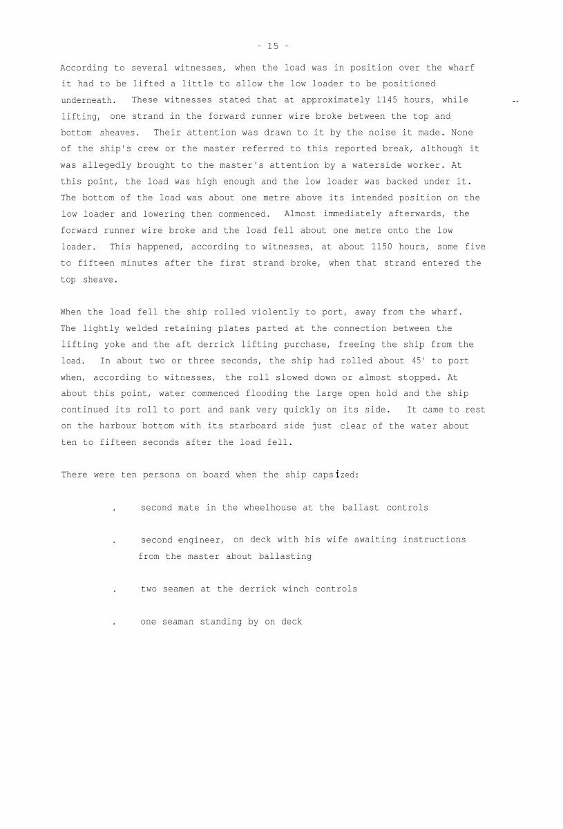
According to several witnesses, when the load was in position over the wharf
it had to be lifted a little to allow the low loader to be positioned
underneath. These witnesses stated that at approximately 1145 hours, while
lifting, one strand in the forward runner wire broke between the top and
bottom sheaves. Their attention was drawn to it by the noise it made. None
of the ship's crew or the master referred to this reported break, although it
was allegedly brought to the master's attention by a waterside worker. At
this point, the load was high enough and the low loader was backed under it.
The bottom of the load was about one metre above its intended position on the
low loader and lowering then commenced. Almost immediately afterwards, the
forward runner wire broke and the load fell about one metre onto the low
loader. This happened, according to witnesses, at about 1150 hours, some five
to fifteen minutes after the first strand broke, when that strand entered the
top sheave.
When the load fell the ship rolled violently to port, away from the wharf.
The lightly welded retaining plates parted at the connection between the
lifting yoke and the aft derrick lifting purchase, freeing the ship from the
load. In about two or three seconds, the ship had rolled about 45' to port
when, according to witnesses, the roll slowed down or almost stopped. At
about this point, water commenced flooding the large open hold and the ship
continued its roll to port and sank very quickly on its side. It came to rest
clear of the water abouton the harbour bottom with its starboard side just
ten to fifteen seconds after the load fell.
There were ten persons on board when the ship caps ized:
. second mate in the wheelhouse at the ballast controls
. second engineer, on deck with his wife awaiting instructions
from the master about ballasting
. two seamen at the derrick winch controls
. one seaman standing by on deck
Page 17
- 16 -
. The ship's cook inside the accommodation near the
galley/provision store area
. a male visitor to the ship on deck near the accomodation area
. two marine surveyors inside the accommodation in the vicinity of
the master's cabin
David Brooke-Smith of Lloyds Register of Shipping
William Martin of Bureau Veritas
The latter two persons were on the ship in connection with damage sustained
when some items of cargo shifted in heavy weather, prior to the ship's arrival
in Port Kembla. They had inspected the damage with a local private marine
surveyor, Gustaaf Keeson, and the Operations Manager of Kahn Shipping, Arnold
van der Heul. The four were proceeding to the master's cabin at about 1145
hours but Gustaaf Keeson went ashore to photocopy some papers, intending to
meet the others in the master's cabin about ten minutes later. Arnold van der
Heul also went ashore briefly to speak to the master who was directing
operations on the wharf. Very shortly after he did so the ship capsized.
The seven crew members, including the second engineer's wife and the male
visitor, who were on the ship when it capsized managed to scramble to safety
on the starboard side or were rescued by a passing fishing vessel or by
persons on the wharf. The master and chief engineer jumped from the wharf
into the water to assist.
Within a few minutes eight persons were accounted for. All, except for one
seaman, were affected a little by immersion and some were taken to hospital
for observation. There were apparently no significant injuries or after
effects of immersion affecting those eight persons.
The master quickly realised that the two surveyors were unaccounted for and
all possible efforts were made by him and other crew members on the capsized
hull to locate them. They were soon joined by emergency rescue services from
ashore, including divers, who arrived on the scene about 1210 hours. The
Page 18
- 17 -
ship's Safety Plan had been quickly recovered from its stowage position on
deck and was used to assist the divers searching the accommodation for the two
missing surveyors.
The body of David Brooke-Smith was found near the entrance to the master's
cabin about 1600 hours, some four hours after the capsize. Divers continued
the search for the other surveyor in very poor conditions caused by debris and
escaping oil, but were forced to abandon their efforts at about 1900 hours.
They resumed the search from about 0800 to 1600 hours the next day and again
from about 0800 to 1300 hours on 16 August. The police in charge of search
operations, considering that further searching was futile, then postponed the
search for William Martin until conditions improved for the divers. His body
was eventually found by the divers on 4 September in the first mate's cabin,
where he was apparently trapped by the door becoming jammed shut, possibly due
to movement of the door frame in the capsize.
Oil escaping from the ship was quickly contained within floating booms
positioned by the Maritime Services Board. Salvage operations were under way
by Monday 18 August, priority being given to sealing the fuel tanks to prevent
further leakage and then removing the oil from the ship. Oil pollution
effects on the harbour were minimal.
Page 19
- 18 -
OBSERVATIONS
1. Documents produced show that GABRIELLA held current certificates in
accordance with all international conventions applicable to ships of her
class and tonnage. The ship was manned in accordance with the
requirements of the Netherlands Administration.
2. GABRIELLA completed building at Waterhuizen in the Netherlands in January
1974 under special survey by Bureau Veritas and was assigned the Bureau's
highest class notation. In addition the design of the ship for handling
and carriage of heavy cargoes was specially studied and approved by the
Bureau.
3. I examined three sections of the broken forward derrick lifting purchase
runner wire with the following results:
WINCH END Apart from damage in the accident, the rope appeared in
good condition. However, there were a number of small filler wires
broken near the rope fracture. Closer examination showed these wires
had corroded inside the rope, the broken ends having sprung out.
These corroded ends ought to have been detected during the required
statutory examination of the rope prior to the accident and should
have led to internal examination. My internal examination of a short
section 15 metres from the break revealed moderately heavy corrosion,
some abrasion and a complete lack of internal lubrication.
FIXED END This section, 23.6 metres in length, was heavily damaged
in the accident over a length of about 4 metres from the break.
Clear of the damage, the rope appeared in good condition apart from a
few broken filler wires as in the winch end.
INTERMEDIATE LENGTH This length of about one metre was found
immediately after the accident by Senior Constable Strik. It
consisted of three strands and the wire rope core which were on the
low loader where the turning frame fell, and two separated strands
found on the wharf alongside the low loader. It is understood that
another four wires, apparently from the missing sixth strand, were
Page 20
- 19 -
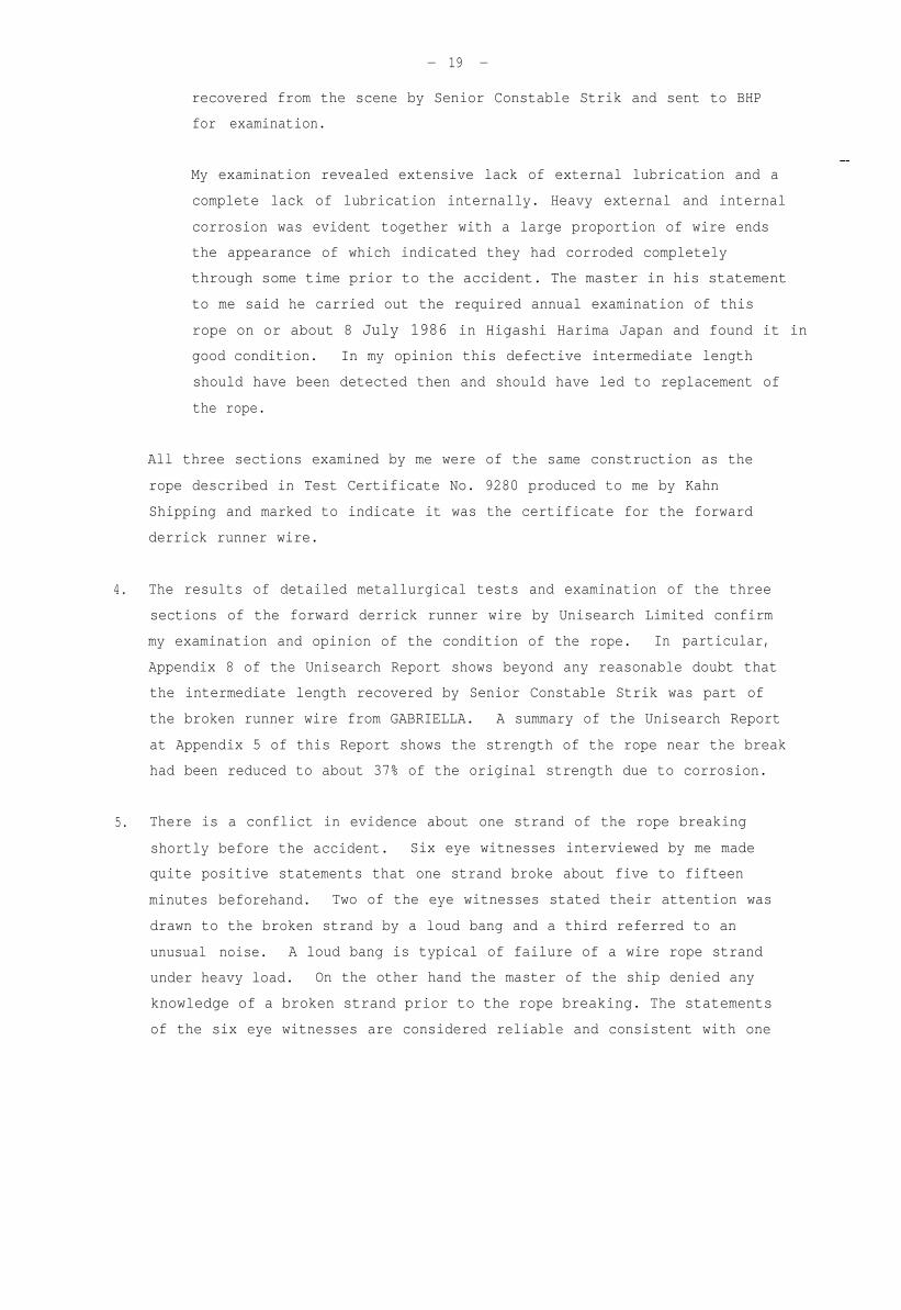
recovered from the scene by Senior Constable Strik and sent to BHP
for examination.
My examination revealed extensive lack of external lubrication and a
complete lack of lubrication internally. Heavy external and internal
corrosion was evident together with a large proportion of wire ends
the appearance of which indicated they had corroded completely
through some time prior to the accident. The master in his statement
to me said he carried out the required annual examination of this
rope on or about 8 July 1986 in Higashi Harima Japan and found it in
good condition. In my opinion this defective intermediate length
should have been detected then and should have led to replacement of
the rope.
All three sections examined by me were of the same construction as the
rope described in Test Certificate No. 9280 produced to me by Kahn
Shipping and marked to indicate it was the certificate for the forward
derrick runner wire.
4. The results of detailed metallurgical tests and examination of the three
sections of the forward derrick runner wire by Unisearch Limited confirm
my examination and opinion of the condition of the rope. In particular,
Appendix 8 of the Unisearch Report shows beyond any reasonable doubt that
the intermediate length recovered by Senior Constable Strik was part of
the broken runner wire from GABRIELLA. A summary of the Unisearch Report
at Appendix 5 of this Report shows the strength of the rope near the break
had been reduced to about 37% of the original strength due to corrosion.
5. There is a conflict in evidence about one strand of the rope breaking
shortly before the accident. Six eye witnesses interviewed by me made
quite positive statements that one strand broke about five to fifteen
minutes beforehand. Two of the eye witnesses stated their attention was
drawn to the broken strand by a loud bang and a third referred to an
unusual noise. A loud bang is typical of failure of a wire rope strand
under heavy load. On the other hand the master of the ship denied any
knowledge of a broken strand prior to the rope breaking. The statements
of the six eye witnesses are considered reliable and consistent with one
Page 21
strand breaking short1 y before the accident.
6. Four of the six eye wi tnesses have stated that when the first strand broke
7.
- 20 -
the master looked up to the head of the forward derrick where the broken
strand was located. Their impression was that the master seemed to be
aware of the broken strand.
The eye witnesses stated that the rope parted when it entered the top
block. Four of them indicated that the break occurred on the fourth
sheave from the right of the top block (looking forward). This is
consistent with the length of the fixed end from the break, 23.6 metres,
and the calculated distance apart of the top and bottom blocks (see
diagram on page 31). It is also consistent with the relatively minor
damage to the winch end compared with the extensive damage to the fixed
end of the broken rope. When the load fell the winch end unreeved through
only one sheave whereas the fixed end unreeved through seven sheaves at a
very rapidly accelerating velocity. Part of the fixed end apparently
became caught up somewhere in the fallen load or gear resulting in the
breaking off of the intermediate length found on the low loader by Senior
Constable Strik. It is notable that one strand from this section of rope
was not found, which supports the allegation that one strand had broken
shortly before the accident. This strand would have partly unravelled
from the rope, and did so according to one of the eye witnesses. Being
unravelled it would have been more exposed to damage while the rope was
rapidly unreeved through the blocks and probably broke up-into a number of
small pieces. It is understood that a number of small pieces were picked
up at the scene by onlookers.
8. Available information indicates that it has been an accepted risk with
ships like 'GABRIELLA' to operate in conditions where capsize is
inevitable in the event of sudden loss of derrick load. It is noted that
the detailed instructions supplied by the owners and operators of
'GABRIELLA' for heavy lift operations make no reference to this. In such
operating conditions it would be prudent to require special examination of
all load bearing gear immediately before use and also to require
evacuation of all non-essential personnel from the ship during the
critical stages.
Page 22
- 21 -
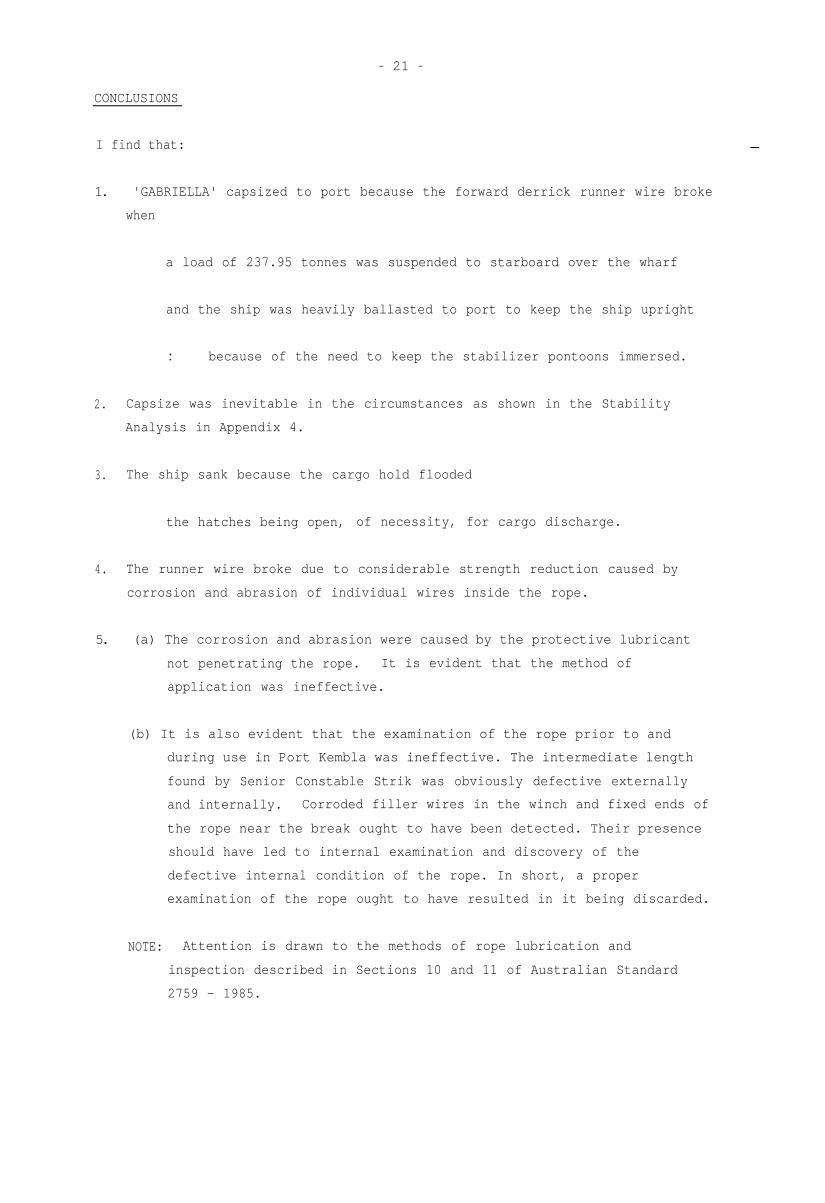
CONCLUSIONS
I find that:
1. 'GABRIELLA' capsized to port because the forward derrick runner wire broke
when
a load of 237.95 tonnes was suspended to starboard over the wharf
and the ship was heavily ballasted to port to keep the ship upright
.. because of the need to keep the stabilizer pontoons immersed.
2. Capsize was inevitable in the circumstances as shown in the Stability
Analysis in Appendix 4.
3. The ship sank because the cargo hold flooded
the hatches being open, of necessity, for cargo discharge.
4. The runner wire broke due to considerable strength reduction caused by
corrosion and abrasion of individual wires inside the rope.
5. (a) The corrosion and abrasion were caused by the protective lubricant
not penetrating the rope. It is evident that the method of
application was ineffective.
(b) It is also evident that the examination of the rope prior to and
during use in Port Kembla was ineffective. The intermediate length
found by Senior Constable Strik was obviously defective externally
and internally. Corroded filler wires in the winch and fixed ends of
the rope near the break ought to have been detected. Their presence
should have led to internal examination and discovery of the
defective internal condition of the rope. In short, a proper
examination of the rope ought to have resulted in it being discarded.
NOTE: Attention is drawn to the methods of rope lubrication and
inspection described in Sections 10 and 11 of Australian Standard
2759 - 1985.
Page 23
- 22 -
6. One strand of the runner apparently broke between five to fifteen minutes
before the final break. It has been alleged that the master was aware of
this, but he said he was not. It is difficult to understand why several
casual observers stated that they noticed it, yet a person of the master's
experience did not. However if the master was not aware of it, it would
appear that he ought to have been.
7. Lowering with the runner after one strand had broken would have imposed
additional stress on the weakened section as it was bent around the next
sheave. The final break apparently occurred at that point, when the
broken strand entered the top block in the sheave furthest from the fixed
end.
8. On the assumption that one strand initially broke, the operation then
would have become very dangerous. Capsize and sinking would have been
inevitable if the rope broke completely. The following action should have
been taken under these circumstances:
. cease all further winching (up or down) of the forward derrick runner
. order all persons from the ship and the danger area on the wharf
immediately
. carefully monitor the partly broken section of rope for indications
of further breaking
. assess options available for landing the load.
9. The following options then should have been considered:
. fill all empty double bottom water ballast tanks
sinkage caused 0.14 M
resultant starboard heel 1.39°, load drops 0.19 M
metacentric height (GM) increases from 2.576 M to 3.075 M
Page 24
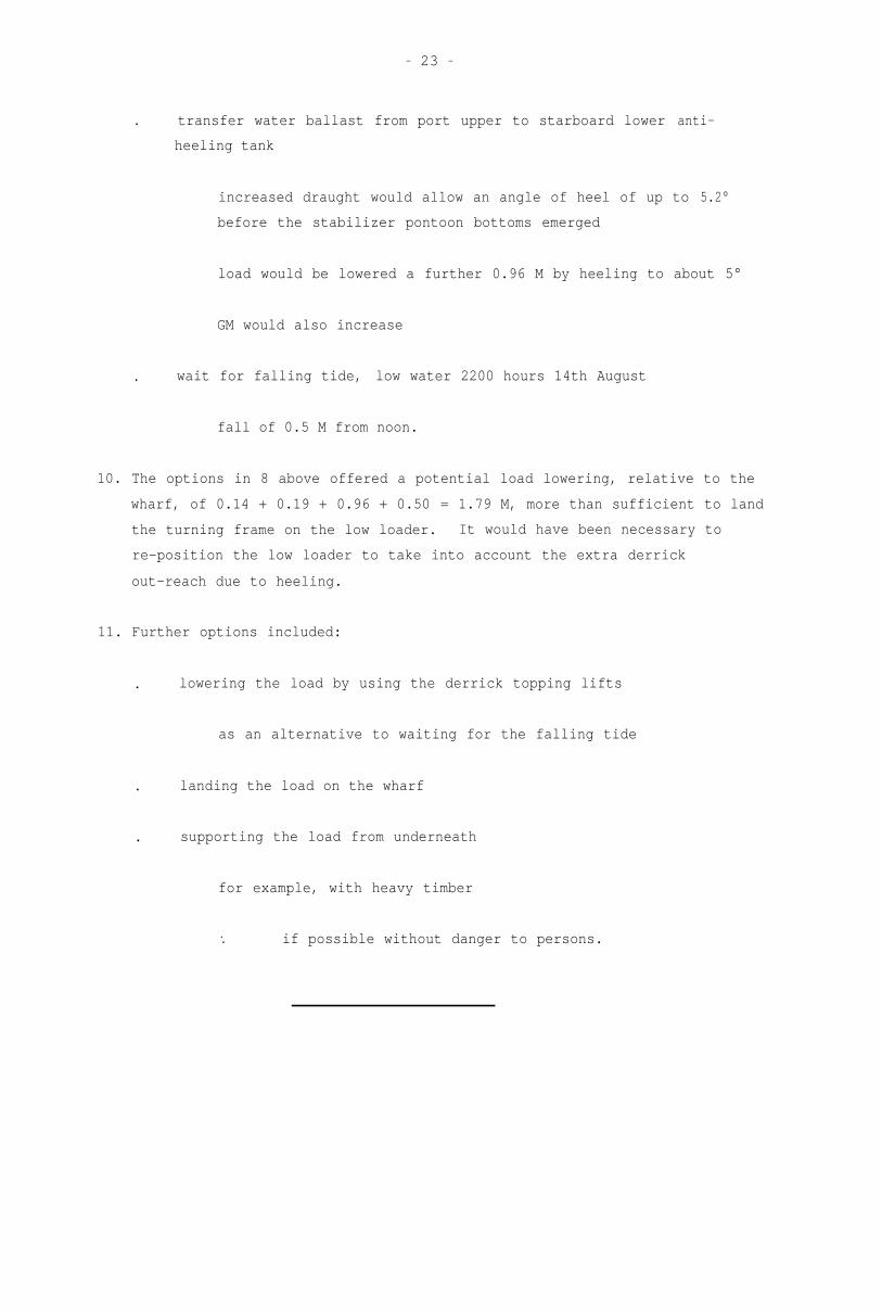
- 23 -
. transfer water ballast from port upper to starboard lower anti-
heeling tank
increased draught would allow an angle of heel of up to 5.2°
before the stabilizer pontoon bottoms emerged
load would be lowered a further 0.96 M by heeling to about 5°
GM would also increase
. wait for falling tide, low water 2200 hours 14th August
fall of 0.5 M from noon.
10. The options in 8 above offered a potential load lowering, relative to the
wharf, of 0.14 + 0.19 + 0.96 + 0.50 = 1.79 M, more than sufficient to land
the turning frame on the low loader. It would have been necessary to
re-position the low loader to take into account the extra derrick
out-reach due to heeling.
11. Further options included:
. lowering the load by using the derrick topping lifts
as an alternative to waiting for the falling tide
. landing the load on the wharf
. supporting the load from underneath
for example, with heavy timber
.. if possible without danger to persons.
Page 25
- 24 -
APPENDIX 1
PARTICULARS OF SHIP
NAME GABRIELLA
PORT OF REGISTRY Willemstad, Curacao, Netherlands Antilles.
OWNERS Jumbo Scheepvaart Maatschappij N.V. Curacao,
Netherlands Antilles.
OPERATORS
TYPE
CONSTRUCTION
BUILT
TONNAGE
Kahn Scheepvaart B.V. (Kahn Shipping Limited)
Rotterdam.
Cargo, specialized heavy lift cargoes.
Steel welded.
Waterhuizen the Netherlands, completed January
1974.
Gross 1327.33 register tons (International)
Net 958.20 register tons (International).
Deadweight 2558 tonnes capacity (to Summer Load
Line).
DIMENSIONS (INTERNATIONAL Length 79.87 metres
TONNAGE CERTIFICATE) Breadth 14.98 metres
Depth 6.32 metres, to upper deck.
PROPULSION MACHINERY One, MAK-type 9 Mu 452 AK, supercharged diesel,
1692 kW.
CLASS Bureau Veritas I 3/3 E + HEAVY CARGO DEEP SEA
Last annual survey of hull and machinery
3 February 1986 Singapore.
Page 26
INTERNATIONAL LOAD
LINE CERTIFICATE
SAFETY CONSTRUCTION
CERTIFICATE
SAFETY EQUIPMENT CERIFICATE Issued by the Netherlands Scheepvaartinspectie on
SAFETY RADIOTELEPHONY
CERTIFICATE
INTERNATIONAL OIL POLLUTION
PREVENTION CERTIFICATE
- 25 -
Issued by the Netherlands Scheepvaartinspectie
(Shipping Inspectorate - Netherlands marine
Administration) on 31 January 1984 and valid to
-31 January 1989. Last annual survey 3 February
1986 Singapore.
Issued by the Netherlands Scheepvaartinspectie
on 31 January 1984 and valid to 31 January
1989. Last annual survey 3 February 1986
Singapore.
25 March 1986 and valid to 9 February 1988.
survey 3 February 1986 Singapore.
Issued by Government of Japan on 9 July 1985
and valid to 8 July 1986. Validity extended
October 1986 by the Netherlands
Scheepvaartinspectie on 13 June 1986.
Last
to 8
Issued by the Netherlands Scheepvaartinspectie
on 16 February 1984 and valid to 30 September
1986. Last annual survey 3 February 1986
Singapore.
CERTIFICATE OF SEAWORTHINESS Issued by the Netherlands Scheepvaartinspectie
(ARTICLE 6 NETHERLANDS SHIPS on 5 June 1985 and valid to 1 July 1987.
ORDER 1965) Validity extended to 1 July 1987 by the
Netherlands Scheepvaartinspectie.
SAFE MANNING DOCUMENT Issued by the Netherlands Scheepvaartinspectie on
5 June 1985 and with same period of validity as
the above Certificate of Seaworthiness to which
it belongs.
CERTIFICATE OF REGISTRY Issued by the Governor of the Netherlands
Antilles at Curacao on 23 January 1978.
INTERNATIONAL TONNAGE
CERTIFICATE EXTRACT
Issued by the Netherlands Chief Inspector for
Tonnage Measurement on 22 October 1974.
Page 27
- 26 -
APPENDIX 2
.
?. . . I
Page 28
- 27 -
APPENDIX 3
STABILITY TERMINOLOGY
The centre of gravity of a body is the point through which the force of
gravity is considered to act vertically downwards with a force equal to the
weight of the body.
The centre of buoyancy is the point through which the force of buoyancy is
considered to act vertically upwards with a force equal to the weight of water
displaced. It is the centre of gravity of the underwater volume.
To float at rest in still water, a vessel must displace its own weight of
water, and the centre of gravity must be in the same vertical line as the
centre of buoyancy.
Figure A represents a ship floating upright in still water. The centres of
gravity and buoyancy are at G and B respectively.
FIG. A FIG. B
If the ship is inclined by an external force to a small angle as shown in
Figure B the centre of gravity will remain at G and the weight of the ship (W)
can be considered to act vertically downwards through this point. The centre
of buoyancy shifts from B to B1.
Page 29
- 28 -
For angles of heel up to about 15o the vertical through the centre of buoyancy
may be considered to cut the centre line at a fixed point called the initial
metacentre (M in the figures). The height of the initial metacentre above the
keel (KM) depends upon a ship's underwater form and the surface waterplane
area.
The vertical distance between G and M is referred to as the metacentric
height. If G is below M the ship has positive metacentric height, and if G is
above M the metacentric height is negative.
A ship is in stable equilibrium if, when inclined, it tends to return to the
initial position. For this to occur the centre of gravity must be below the
metacentre. Figure A shows a ship in the upright position having a positive
GM. Figure B shows the same ship inclined to a small angle. The centre of
buoyancy moves from B to B1 to take up the new centre of gravity of the
underwater volume, and the force of buoyancy is considered to act vertically
upwards through B1 and the metacentre M. If moments are taken about G there
is a moment to return the ship to the upright. This moment is referred to as
the Moment of Statical Stability and is equal to the product of the force (W)
and the length of the lever GZ.
FIG C
When a ship which is inclined to a small angle tends to heel over still
further, it is in unstable equilibrium. For this to occur the ship must have
a negative GM.
Figure C shows a ship in unstable equilibrium which has been inclined to a
small angle. The moment of statical stability, W x GZ, is clearly a capsizing
moment which will tend to heel the ship still further.
Page 30
- 29 -
APPENDIX 4
STABILITY ANALYSIS
The following calculations are based on:
.copies of the ship's stability data
approved by the Netherlands Shipping
Inspectorate and supplied by the ship's
operators Kahn Shipping
.statements by the master and first mate
and information on the ship's cargo plan
relating to the cargo on board
.statements by the master, chief engineer
and second mate relating to liquids in tanks
.information from Kahn Shipping and the
master, based on operating experience,
relating to the estimated quantities of
unpumpable liquids in tanks
.information from BHP about the weight of
the turning frames
.measurement of the distance from the wharf
face to the centre of the turning frame
where it dropped and hence the outreach of
the derricks at the time of the accident
.a general arrangement plan of the ship
supplied by Kahn Shipping.
The analysis shows the stability conditions of the ship immediately before and
after the turning frame dropped. Although some of the factors involved,
notably the quantities of unpumpable liquids, are necessarily only estimates,
Page 31
- 30 -
they are considered sufficiently accurate for the purpose of this
investigation. In the absence of information in the data relating to centre
of gravity and free surface in the partly filled condition of some tanks, the
partly filled centres of gravity have been estimated and the maximum free
surface moments have been used. The ship's condition was, therefore, probably
very slightly better than shown by the calculations. Any difference, however,
is of no practical significance. The absence in the data supplied of the
effect of trim of the ship is also considered to be of no practical effect on
the results of these calculations. Certainly, the calculated angle of heel
immediately prior to the accident accords with the master's statement that he
ballasted the ship to keep the angle of heel very slightly to starboard of
upright, about ½°.
The curve of righting levers (GZ) has been drawn past the angle of heel at
which the hold would have commenced flooding. This illustrates that capsize
was inevitable even if the hold was not open, as the capsizing levers are
always greater than the righting levers. It is not suggested that the upper
deck hatch covers should have been, or even could have been, secured in place
by the wharf cranes when the turning frame was clear of the hold. Such a
course of action, even if feasible, would have been undesirable for safety
reasons.
This analysis shows that the stability was satisfactory for the discharge of
the second turning frame. However, at the critical stage with the turning
frame over the wharf, the amount of cargo and water ballast used to counter-
balance the turning frame and keep the stabilizer pontoons immersed was such
that capsize was inevitable if the load in the derricks were suddenly lost.
With the cargo hold open for cargo discharge the consequence of capsize was
sinking.
The analysis also shows that even if the turning frames could have been
discharged before other cargo in the hold, the improved stability would not
have been sufficient to prevent capsize and sinking.
Page 32
- 31 -
CONDITION IMMEDIATELY BEFORE ACCIOENT
SCALE 1:100
Calculations for CG of load above baseshow it located 12.24 M above derrickneel which is 11.2 M above base.
.-. KG of load 23.44 M - compares closelyJith scale drawing on right.
Note : Distance between centres oflifting yoke supports = 17.5 M.
HER. -
Above calculations based on centreof yoke length being equidistantfrom derrick heels.
LOAD OUTREACH 10.9Il
II
LOWER SIDE OF TOP
Ys
5ia
Page 33
- 32 -
ITEM
STBD+
WEIGHT KG V.MOM LCG L.MOM TCG T.MOM
(tonnes) (m) (t-m) (m) (t-m) (m) (t-m)
Lightship excluding following 1546 7.13Fore derrick 18 19.0Aft derrick 18 19.0Stabilizer beams
14Y7.0
Tween deck hatch No. 1 1.48II II II " 2 11:4 1.48I, II ,, " 3 11.4 1.48II II II " 4 11.4 1.48II II II " 5 11.4 1.48
Stores7:
12.3Lifting/Lashing gear 7.0
Sub-Total 1734 12472 59854 - 96
Less Nos. 3-7 upper deckhatches placed ashore
No. 8 upper deck hatchashore
No. 2 hatch moved on top
No. 1
-72
-20
11018 33.23 51374 -0.18342 52.79 950 7.3342 32.17 579 7.370 29.00 290 -8.021 60.41 864 -17 52.45 598 -17 47.09 537 -17 41.73 476 -17 36.37 415 -86 3.00
525 50.00 37;: :
-278
131
131
- 80
8.65
8.65
+0.45
-622 36.34 -2616 -
-174 19.00 - 380 -
+ 6 +5.5 + 79 -
ADJUSTED LIGHTSHIP 1642 11682 56937 - 96
____________________~~~~~~~~~~~~~~~~~~~~~~~~~~~~~~~~~~~~~~~~~~~~~~~~~~~~~~~~~~
Page 34
- 33 -
LIQUIDS WEIGHT
(tonnes)
STBD F.S.
V.MOM LCG L.MOM +TCG T.TOM MOM
(t-m) (m) (t-m) (m) (t-m) (t-m)
2 DB Port Fuel Oil' Stbd
; IIII II
Centre I' 'I4 II II II II
Settling TankPort 'I 'I
Settling TankStbd " "
Day Tank Stbd I' 'I4 DB Port Lub. '5 " " II IIII II Stbd Leak I'4 II II Dirty 'IFresh Water Tank Port
II II II StbdAft Peak - Fresh WaterFore Peak Water Ballast1 DB Centre IIII II Port IIII I, Stbd II'I Upper Wing Tank
Port II'I Upper Wing Tank
Stbd '2 DB Centre II'I Lower Wing Tank
Port II'I Lower Wing Tank
Stbd ''I Upper Wing Tank
Port II
50
:57
0.610.060.060.61
31
-35
37.04 185237.04 18535.7 17921.6 1231
-2.92 - 1462.92 15 :“6
6673
14 8.19 115 9.31 130 -5.82 - 81 0
3 7.62 10.03 0.82 0.81 0.82 0.88 8.32 8.0
30 5.033 6.1163 0.6732 0.678 0.17
2220221
6:
151:20242211
9.31
1:::910.2810.2811.990.220.223.3
71.5861.5554.454.4
281236
::242
5.821.9
-1.61-1.291.291.61
-4.084.08
23:;38781741435
174531
- 3;8
80301355
95
-3.5 - ;123.5 28
19
:
243
30
30
2318
25
2
6.64
6.00.05
2.78
0.35
6.05
5.60.680.17
6.67
6.0
126 53.86 1023 -6.52 - 124
12 53.86 10849.09 245
6.52 13
675 37.07 9008 -6.16 -1497
11 37.07 1112 4.8 144
182 37.05 1112 -6.6 - 197
11 37.0521 19.671 19.67
6::157
6.6 13T3.46 - 1073.46 28
043
0
3366
0
22
9
8
39
167 18.89 473 -6.44 - 161
12 18.89 38 6.44 13 3
2 Upper Wing TankStbd '
3 DB Port IIII II Stbd II'I Upper Wing Tank
Port 'I'I Upper Wing Tank
Stbd '
TOTAL LIQUIDS 717 1946 26185 -2179 514
Page 35
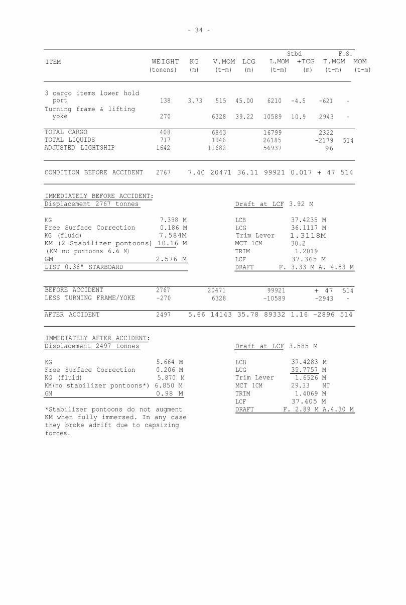
- 34 -
ITEM
Stbd F.S.WEIGHT KG V.MOM LCG L.MOM +TCG T.MOM MOM
(tonens) (m) (t-m) (m) (t-m) (m) (t-m) (t-m)
3 cargo items lower holdport 138 3.73 515 45.00 6210 -4.5 -621 -
Turning frame & liftingyoke 270 6328 39.22 10589 10.9 2943 -
TOTAL CARGO 408 6843 16799 2322 -TOTAL LIQUIDS 717 1946 26185 -2179 514ADJUSTED LIGHTSHIP 1642 11682 56937 - 96 -
CONDITION BEFORE ACCIDENT 2767 7.40 20471 36.11 99921 0.017 + 47 514
IMMEDIATELY BEFORE ACCIDENT:Displacement 2767 tonnes Draft at LCF 3.92 M
KG 7.398 M LCB 37.4235 MFree Surface Correction 0.186 M LCG 36.1117 MKG (fluid) 7.584M Trim Lever 1.3118MKM (2 Stabilizer pontoons) 10.16 M MCT 1CM 30.2(KM no pontoons 6.6 M) TRIM 1.2019 GM 2.576 MLIST 0.38" STARBOARD
LCF 37.365 MDRAFT F. 3.33 M A. 4.53 M
BEFORE ACCIDENT 2767 20471 99921 + 47 514LESS TURNING FRAME/YOKE -270 6328 -10589 -2943 -
AFTER ACCIDENT 2497 5.66 14143 35.78 89332 1.16 -2896 514
IMMEDIATELY AFTER ACCIDENT:Displacement 2497 tonnes Draft at LCF 3.585 M
KG 5.664 MFree Surface Correction 0.206 MKG (fluid) 5.870 MKM(no stabilizer pontoons*) 6.850 M
GM 0.98 M
*Stabilizer pontoons do not augmentKM when fully immersed. In any casethey broke adrift due to capsizing
forces.
LCB 37.4283 MLCG 35.7757 MTrim Lever 1.6526 MMCT 1CM 29.33 MT
TRIM 1.4069 M
LCF 37.405 MDRAFT F. 2.89 M A.4.30 M
Page 36
- 35 -
TABLE OF CAPSIZING LEVERS KG 5.87 DISPLACEMENT 2497
HEEL ANGLE 0 5 10 15 20 25 30 35 40 45 50 55 60 65 70
KGK;IN HEEL 0 0 0.60 0.51 1.20 1.02 1.79 1.52 2.37 2.01 2.92 2.48 3.475 2.935 4.34 3.77 4.98 4.50 5.325 5.085 5.4 5.5
ANGLE
RIGHTINGLEVER 0 0.09 0.18 0.27 0.36-0.44 0.54 0.58 0.57 0.52 0.48 0.36 0.24 -0.1
CAPSIZINGLEVER 1.16 1.16 1.14 1.12 1.09 1.05 1.00 0.95 0.89 0.82 0.75 0.67 0.58 0.49 0.4
RESULTANTLEVER 1.16 1.07 0.96 0.85 0.74 0.61 0.46 0.37 0.32 0.30 0.27 0.31 0.34 0.5
(CAPSIZING)
NOTE 1 GZ values are for intact hull. Vessel's cargo hold was open and
angle of flooding for hold coaming was 46°. Although GZ values
are not correct past 46° (they would be much less), the curvesshow the capsizing lever is always greater than the rightinglever and capsize was inevitable, even if the hold was not open.
NOTE 2 There are no KN curves in the ship's data for 35° 45° 55° &
65°. GZ values at these angles have been extracted from GZ
curves in the data for angles of heel 0° to 60°.
CURVES OF CAPSIZING & RIGHTING LEVERS
Page 37
- 36 -
CONDITION IF TURNING FRAMES DISCHARGED BEFORE OTHER CARGO IN HOLD
ITEM
Stbd+ F.S.
WEIGHT KG V.MOM LCG L.MOM TCG T.MOM MOM
Turning frame & lifting
yoke4 x 45.7T items6 x 46.6 '3 x 42.6 '4 x 34.8 '
1 x 46.6 '
1 x 32.2 '1 x 32.9 fl2 x 10.3 II1 x 4.5 II
30 items
270183 3.73280 3.73128 3.73139 3.2247 3.27
32 2.95
33 2.5021 2.05
5 4.3727 3.20
6328682
1043477
448152
95
8242
::
TOTAL CARGO 1165 9455 2322 -TOTAL LIQUIDS 717 1946 -2179 514ADJUSTED LIGHTSHIP 1642 11682 - 9 6 -
CONDITION BEFORE "ACCIDENT" 3524 6.55 23083 47 514LESS TURNING FRAME/YOKE -270 6328 -2943 -.
AFTER "ACCIDENT" 3254 5.149 16755 -2896 514
Displacement 3254 tonnes Draft at LCF 4.50M
KG 5.149M Hold flooding angle 39°
Free Surface Correction .158M Righting lever at 35° 0.72M
KG (fluid) 5.307M Capsizing lever at 35° 0.95M
KM (no stabilizer pontoons) 6.350M Righting lever at 40° 0.78M
GM 1.043M Capsizing lever at 40° 0.89M
NOTE 1 Trim is not significant and has been omitted
NOTE 2 3 cargo items totalling 138 tonnes have been 'discharged' from thestarboard side of the hold first and are not included in the above
calculations. This provides the required extra weight on the port
side. The transverse moment (T.Mom) after the hypothetical accidentabove is therefore the same as after the actual accident (see page
34).
Page 38
- 37 -
APPENDIX 5
SUMMARY OF RESULTS OF EXAMINATION AND TESTS
BY UNISEARCH LTD, UNIVERSITY OF NEW SOUTH WALES
"Failure of the fore derrick running rope of MV 'GABRIELLA' at Port Kembla
harbour on 14 August 1986 is attributed to the rope being so heavily
internally corroded that the breaking load of the rope was exceeded by the
combined forces of lifted load and the bending of the rope in the sheaves. On
the basis of tensile tests on sections of the rope and individual wires, the
breaking load of the rope had decreased from an initial value of 94.4 tonnes
in 1981 to an estimated failure load at the break of 35 tonnes. While the
contribution to the total lifted load of 265.6 tonnes from each of the 10
falls in the reeving system was only 13.28 tonnes, it is considered that the
stiffness of the rope had been increased by corrosion and a force of at least
30 tonnes was developed in bending the rope around the sheaves. This was
sufficient to cause failure of the rope.
Although formulated for marine conditions, the grease used to lubricate the
rope did not penetrate the internal strands and, furthermore, was so badly
deteriorated that 50 percent of the grease consisted of rust. Standard
procedures for internal inspection of the rope would have identified the state
of corrosion and lack of internal lubrication. In lowering after the alleged
failure of one strand, appreciable additional bending forces would have been
imposed on the weakened rope such that failure took place in the sheave."