43


Contents
Introduction ................................................................................................ 1
Standard Panels .......................................................................................... 2
Fasteners ................................................................................................... 5
“R” Panel Trim ............................................................................................. 6
“R” Panel Info .............................................................................................. 9
Tex-Rib Trim .............................................................................................. 10
Tex-Rib Info ............................................................................................... 12
“U” Panel Trim ........................................................................................... 13
“U” Panel Info ............................................................................................ 15
General Trim ............................................................................................. 16
Building Diagram ....................................................................................... 20
Metal Building Kits ..................................................................................... 22
Doors ....................................................................................................... 23
Skylight Panels .......................................................................................... 24
Insulation .................................................................................................. 25
Accessories .............................................................................................. 26
Sub-Structural Components ........................................................................ 30
Terms & Conditions of Sale ........................................................................ 40

www.sawyermetal.com 1
Sawyer Metal is a family owned business that was established in 1979 by F.E. “Frank” Sawyer. Frank began his business with a pickup truck, some borrowed tools, and an old fashioned work ethic. After many years of hard work, Sawyer has expanded from its humble beginnings in construction into the largest manufacturer of metal building and roofing components in East Texas.
We are committed to excellence in the manufacturing of metal roofing and steel building products. We appreciate our customers, and we are devoted to exceeding their expectations. It is our promise to maintain honesty and integrity while we produce a superior product and customer service.
Introduction

2
“R” Panel
Tex-Rib
36” net coverage12” 1” ¾
13⁄8
1¼”
Optional PerlinBearing Leg
Our Tex-Rib with its anti-siphon feature gives you a weather-tight seal.
3⁄16
35⁄64”4”4”4”
3⁄32
36” net coverage
37¾”
9” 1¾” ¾
¾”
31⁄8” 2¾”
“R” Panel
“R” Panel is a multi-use wall and roof panel used primarily in pre-engineered metal building applications.
“R” PANELFASTENING METHODS
FASTENER(PATTERN #1)
FASTENER(PATTERN #2)
TAPE SEALANTROOF PANEL SEAMS ONLY
STITCH FASTENER(1’ - 8 O.C.)
TAPE SEALANTROOF PANEL SEAMS ONLY
STITCH FASTENER(1’ - 8 O.C.)
The use of proper fasteners and installation procedures is an important factor in the appearance and performance of the panel system. Roofing and siding may be installed using fasteners with weather seal washers.
Sawyer Metal shall not be liable for any claim or claims which arise out of the handling or installation of the material.
METAL FASTENERS
Sealing material slightlyvisible at edge of metalwasher. Assembly isweathertight.
Sealing material notvisible. Not enoughcompression to sealproperly.
Sealing material extrudedbeyond edge of washer.
CORRECT TOO LOOSE TOO TIGHT
Sealing material notvisible. Not enoughcompression to sealproperly.
TOO LOOSESealing material slightlyvisible at edge of nail head.Assembly is weathertight.
CORRECT
NAILS
Sealing material extrudedbeyond edge of washer.
TOO TIGHT

www.sawyermetal.com 3
Tex-Rib
“R” Panel
Tex-Rib
36” net coverage12” 1” ¾
13⁄8
1¼”
Optional PerlinBearing Leg
Our Tex-Rib with its anti-siphon feature gives you a weather-tight seal.
3⁄16
35⁄64”4”4”4”
3⁄32
36” net coverage
37¾”
9” 1¾” ¾
¾”
31⁄8” 2¾”
Tex-Rib is a low profile (3/4”) panel that is well suited for commercial, agricultural and residential applications. Tex-Rib can be installed on as low as a 1:12 pitch
if sealant is used on the sidelaps. If not, a 3:12 pitch is recommended.
Our Tex-Rib with its anti-siphon feature gives you a weather-tight seal.
Tex-RibFASTENING METHODS
FASTENER(PATTERN #2)
FASTENER(PATTERN #1)
STITCH FASTENER(1’ - 8 O.C.)
STITCH FASTENER(1’ - 8 O.C.) TAPE SEALANT
ROOF PANEL SEAMS ONLY
TAPE SEALANTROOF PANEL SEAMS ONLY
The use of proper fasteners and installation procedures is an important factor in the appearance and performance of the panel system. Roofing and siding may be installed using fasteners with weather seal washers.
Sawyer Metal shall not be liable for any claim or claims which arise out of the handling or installation of the material.
METAL FASTENERS
Sealing material slightlyvisible at edge of metalwasher. Assembly isweathertight.
Sealing material notvisible. Not enoughcompression to sealproperly.
Sealing material extrudedbeyond edge of washer.
CORRECT TOO LOOSE TOO TIGHT
Sealing material notvisible. Not enoughcompression to sealproperly.
TOO LOOSESealing material slightlyvisible at edge of nail head.Assembly is weathertight.
CORRECT
NAILS
Sealing material extrudedbeyond edge of washer.
TOO TIGHT

“U” Panel
4
“U” Panel
36” net coverage6” (typ.) 11⁄32”
¾”
Optional PerlinBearing Leg
215⁄32”
373⁄16”
“U” Panel is an exposed fastener wall and roof panel that is mainly used as a liner or partition panel.
“U” PanelFASTENING METHODS
FASTENER(PATTERN #1)
STITCH FASTENER(1’ - 8” O.C.)
FASTENER(PATTERN #2)
STITCH FASTENER(1’ - 8” O.C.) TAPE SEALANT
ROOF PANEL SEAMS ONLY
TAPE SEALANTROOF PANEL SEAMS ONLY
The use of proper fasteners and installation procedures is an important factor in the appearance and performance of the panel system. Roofing and siding may be installed using fasteners with weather seal washers.
Sawyer Metal shall not be liable for any claim or claims which arise out of the handling or installation of the material.
METAL FASTENERS
Sealing material slightlyvisible at edge of metalwasher. Assembly isweathertight.
Sealing material notvisible. Not enoughcompression to sealproperly.
Sealing material extrudedbeyond edge of washer.
CORRECT TOO LOOSE TOO TIGHT
Sealing material notvisible. Not enoughcompression to sealproperly.
TOO LOOSESealing material slightlyvisible at edge of nail head.Assembly is weathertight.
CORRECT
NAILS
Sealing material extrudedbeyond edge of washer.
TOO TIGHT

www.sawyermetal.com 5
Fasteners
OTHER SIZES ALSO AVAILABLE WITH MINIMUM
QUANTITY ORDER.CALL FOR DETAILS.
STOCKED SIZES
STOCKED SIZES
• Fastener designed to attach metal roof and sidewall panels used in pre-engineered metal building applications.
• #12 Diameter 5/16” Cupped HWH self-drilling fastener easily penetrates steel up to .210” in thickness with no “point walking”. 1/4” Stitch will securely fasten 2 layers of 26 GA with no strip-out.
• Cupped head & washer encapsulate EPDM rubber washer & provide a secure seal even when driven at an angle.
FOR PROPER APPLICATION, THE USE OF IMPACT DRIVERS ARE NOT RECOMMENDED FOR POWDER COATED OR ANY WET PAINTED FASTENER
• Fastener designed to attach steel roofing & siding used in post-frame & residential metal roofing applications.
• Threads transition from fine to coarse to generate superior holding strength in various wood substrates.
• Sharp Point & pronounced lead thread consistently drills high tensile 29 & 26 gauge steel with no “point walking.”
• Type 17 point reduces metal shavings that can embed themselves in the rubber washer.
• EPDM rubber is vulcanized to a steel washer to form an excellent seal even when driven at an angle.
FOR PROPER APPLICATION, THE USE OF IMPACT DRIVERS ARE NOT RECOMMENDED FOR POWDER COATED OR ANY WET PAINTED FASTENER
NOTES: All strength values shown above are ultimate values, expressed in LBS. Apply an appropriate safety factor to obtain design limits.
SIZE 12” X 1-1/4” 1/4” X 7/8”STITCH
HEAD STYLE
5/16” CHWH*
5/16” CHWH*
CARTON QTY.
2500 2500
WEIGHT/M
14.8 13.4
SIZE 10” X 1” 10” X 1-1/2”
HEAD STYLE
1/4” HWH 1/4” HWH
CARTON QTY.
3000 2500
WEIGHT/M
8.0 10.1*C
UPPE
D HE
X W
ASHE
R HE
AD

6
“R” Panel Trim
4”
6 ½”
4”
4”
1”
¾”
Pitch
4”
4”
4”
4”
6 ½”
¾”
Pitch
1”
9”
45°
½”
4”
4” 2”
¾”
1 ¾”
1 ¾”
4 ¼”
4”
4” 2”
1 ¾”
8”
Pitch
5 ¼”
1 ¾”
½”
¾”
4”1/12 OnlyNO FIELDASSEMBLY
SCULPTURED POST-HUNG GUTTER SCULPTURED PRE-HUNG GUTTER SCULPTURED GUTTER END CAP
GUTTER SUPPORTS SCULPTURED RAKE HIGHSIDE SCULPTURED RAKE
SCULPTURED RAKE END CAP RESIDENTIAL RAKE SCULPTURED CORNER BOX
STR-1 STR-2
GIRTH = 21 1⁄4”SPECIFY PITCH
GIRTH = 23 3⁄4”SPECIFY PITCH
GIRTH = 20 1⁄2”GIRTH = 19”
TO FIT SCULPTURED GUTTER ONLY
TO FIT SCULPTURED RAKE SPECIFY R/LGIRTH = 12 3⁄4”
STR-3
STR-4 STR-5 STR-6
STR-7 STR-8 STR-9

www.sawyermetal.com 7
“R” Panel Trim
18”
1/12 Min4/12 Max
3 ½”
1 ¾”
1 ¾”
3 ½”
¾”
¾”
‘
4 ½”
1 ¾”
1 ¾”
4 ½”
¾”
¾”
‘
2 1⁄8”
1”
1 3⁄8”
2 1⁄8”
1”
1 3⁄8”
½”1 ¾”
¾”
4”
5”
‘
½”
3 1⁄8”
1 ½”
‘
1 ¾”4 1⁄8”
3 ½”
¾”
16”2”
1 ½” 1 ¾”
‘
SCULPTURED PEAK BOX OUTSIDE CORNER INSIDE CORNER
HEAD TRIM JAMB TRIM SIDEWALL
BASE TRIM CORNER PIER CAP (Mini Warehouse) ZEE FLASHING
STR-10 STR-11
TO FIT SCULPTURED RAKE GIRTH = 13”
GIRTH = 12”
GIRTH = 15”
GIRTH = 5 5⁄8” GIRTH = 26 1⁄8”
STR-12
STR-13 STR-14 STR-15
STR-16 STR-17 STR-19
GIRTH = 5 3⁄4”
GIRTH = 5”GIRTH = 5”

8
“R” Panel Trim
1 11⁄16” 1 11⁄16”
8 1⁄8”
JAMB HEAD COVER DIE FORM RIDGE CAP
R-PANELCONTINUOUS DIE FORMED FLASHING
SPECIFY PITCHGALVALUME ONLY10’ ONLY
NOTES:
GIRTH = 12 1⁄2”SPECIFY PITCH
MAX PITCH = 4:12AVAILABLE 2’6” OR 3’
STR-20 STR-21
STR-22

www.sawyermetal.com 9
“R” Panel Info
Ga. KSI 3’ 4’ 5’ 6’ 7’ 8’ 3’ 4’ 5’ 6’ 7’ 8’ 3’ 4’ 5’ 6’ 7’ 8’
29 80 97 55 35 24 18 14 91 51 32 19 12 * 0.12 0.22 0.33 0.40 0.47 0.53
26 80 150 84 54 37 27 21 133 75 47 27 17 12 0.12 0.22 0.33 0.40 0.47 0.53
26 50 134 75 48 33 25 19 112 63 40 28 18 12 0.10 0.17 0.27 0.39 0.47 0.53
24 80 204 115 74 51 38 29 162 91 58 34 22 14 0.12 0.21 0.33 0.40 0.47 0.53
24 50 178 100 64 45 33 25 136 77 49 34 22 15 0.10 0.17 0.27 0.38 0.47 0.53“R” Panel
Tex-Rib
36” net coverage12” 1” ¾
13⁄8
1¼”
Optional PerlinBearing Leg
Our Tex-Rib with its anti-siphon feature gives you a weather-tight seal.
3⁄16
35⁄64”4”4”4”
3⁄32
36” net coverage
37¾”
9” 1¾” ¾
¾”
31⁄8” 2¾”
“R” Panel
Tex-Rib
36” net coverage12” 1” ¾
13⁄8
1¼”
Optional PerlinBearing Leg
Our Tex-Rib with its anti-siphon feature gives you a weather-tight seal.
3⁄16
35⁄64”4”4”4”
3⁄32
36” net coverage
37¾”
9” 1¾” ¾
¾”
31⁄8” 2¾”
POSITIVE WIND LOAD LIVE LOAD DEFLECTION (IN)
“R” PANEL ALLOWABLE LOAD (PSF)*
“R” PANEL SECTION PROPERTIES
NOTES:1. Allowable uniform loads are based upon equal span lengths.2. Positive Wind is wind pressure and is increased by 33 1/3%.3. Negative Wind is wind suction or uplift and is increased by
33 1/3%.4. Live is the allowable live or snow load.5. Deflection (L/180) is the allowable load that limits the panels
deflection to L/180.6. Deflection (L/240) is the allowable load that limits the panels
deflection to L/240.7. The weight of the panel has not been deducted from the
allowable loads.8. Web crippling has not been checked for the allowable loads
shown above.
1. Section properties are calculated in accordance with the 1986 Edition of the Cold Formed Steel Design Manual.
2. Ix is for deflection determination.
3. Se is for bending.
4. Ma is the allowable bending moment.
5. All values are for one foot of panel width.
* Oil canning is a natural occurrence in metal and is not cause for panel rejection.
TOP IN COMPRESSION BOTTOM IN COMPRESSION
Panel Gauge
Weight PSF
KYKSI
IxIN.4
SeIN.3
MaKIP IN.
IxIN.4
SeIN.3
MaKIP IN.
29 0.69 80 .0247 .0219 .7883 .0242 .0301 1.082
26 0.88 80 .0371 .0337 1.211 .0349 .0400 1.437
26 0.88 50 .0394 .0362 1.085 .0361 .0405 1.211
24 1.04 80 .0454 .0460 1.654 .0444 .0486 1.746
24 1.04 50 .0474 .0482 1.442 .0457 .0491 1.469

4 1⁄8”
1”
1”
4 1⁄8”
¾”
¾”
‘
4”
1”
1”
4”
¾”
¾”
‘
4 1⁄8”
1”
½”
¾”
3 3⁄8”
‘
2 5⁄8”
7⁄8”
1”
2 5⁄8”
7⁄8”
½”
1”
½”
2 ¼”
1”
‘
1”
¾”
4”
3 3⁄8”
‘ 4 ¼”
½”
8 1⁄8”
‘
¾”
70°
½”
9”
OUTSIDE CORNER INSIDE CORNER RESIDENTIAL RAKE
HEAD TRIM JAMB TRIM BASE TRIM
SIDE WALL TIE IN HIGHSIDE TRIM GUTTER SUPPORTS
STT-1 STT-2
GIRTH = 12 3⁄4”
GIRTH = 5”
GIRTH = 12 1⁄2”
GIRTH = 5” GIRTH = 4 1⁄4”
GIRTH = 13 3⁄4”
GIRTH = 10 3⁄4”
GIRTH = 9 5⁄8”
STT-3
STT-4 STT-5 STT-6
STT-7 STT-8 STT-9
10
Tex-Rib Trim

4 ¼”
¾”
¾”
1”
1”
6 ¼”
‘
4 ¼”
¾”1”
3 ¼”
‘
4”
4” 2”
¾”
1 ¾”
1”
4 1⁄8”
4”
4” 2”
1 ¾”
8”
Pitch 4”
4”
4”
1”
7”
¾”
Pitch
4”
4”
4”
3”
7”
¾”
Pitch
RAKE & GABLE TRIM SHINGLE RAKE TRIM SCULPTURED RAKE
SCULPTURED RAKE END CAP
STT-10 STT-11
GIRTH = 15”
TO FIT SCULPTURED RAKE
GIRTH = 9 3⁄4” GIRTH = 18 1⁄8”
STT-13
STT-14
STT-17
STT-15
STT-18
STT-16
www.sawyermetal.com 11
Tex-Rib Trim
HIGHSIDE SCULPTURED RAKE
GIRTH = 20 1⁄2”
SCULPTURED POST-HUNG GUTTER
GIRTH = 21 3⁄4”SPECIFY PITCH
SCULPTURED PRE-HUNG GUTTER GUTTER END CAP
GIRTH = 23 1⁄4”SPECIFY PITCH TO FIT SCULPTURED GUTTER ONLY

Tex-Rib Info
12
Ga. KSI 2’ 2.5’ 3’ 4’ 5’ 6’ 2’ 2.5’ 3’ 4’ 5’ 6’ 2’ 2.5’ 3’ 4’ 5’ 6’
29 80 158 101 70 36 19 11 118 76 53 27 14 8 0.11 0.17 0.24 0.40 0.50 0.60
26 80 206 132 92 48 25 14 155 99 69 36 18 11 0.11 0.17 0.24 0.40 0.50 0.60
26 50 134 86 59 33 21 15 100 64 45 25 16 11 0.07 0.11 0.15 0.27 0.42 0.60
24 80 263 168 117 61 31 18 197 126 88 46 23 14 0.11 0.17 0.24 0.40 0.50 0.60
24 50 170 109 76 43 27 19 128 82 57 32 20 14 0.07 0.10 0.15 0.27 0.42 0.60
“R” Panel
Tex-Rib
36” net coverage12” 1” ¾
13⁄8
1¼”
Optional PerlinBearing Leg
Our Tex-Rib with its anti-siphon feature gives you a weather-tight seal.
3⁄16
35⁄64”4”4”4”
3⁄32
36” net coverage
37¾”
9” 1¾” ¾
¾”
31⁄8” 2¾”
“R” Panel
Tex-Rib
36” net coverage12” 1” ¾
13⁄8
1¼”
Optional PerlinBearing Leg
Our Tex-Rib with its anti-siphon feature gives you a weather-tight seal.
3⁄16
35⁄64”4”4”4”
3⁄32
36” net coverage
37¾”
9” 1¾” ¾
¾”
31⁄8” 2¾”
POSITIVE WIND LOAD LIVE LOAD DEFLECTION (IN)
TEX-RIB ALLOWABLE LOAD (PSF)*
TEX-RIB SECTION PROPERTIES
NOTES:1. Allowable uniform loads are based upon 3 equal span
lengths.2. Positive Wind is wind pressure and is increased by 33 1/3%.3. Live is the allowable live or snow load.4. Deflection is actual deflection when loaded with the
corresponding live load.5. The weight of the panel has not been deducted from the
allowable loads.6. Web crippling has not been checked for the allowable loads
shown above.
The Tex-Rib profile is one of the most well-suited designs for both commercial and industrial use. It has also shown tremendous growth in popularity as a residential roofing panel.
* Oil canning is a natural occurrence in metal and is not cause for panel rejection.
TOP IN COMPRESSION BOTTOM IN COMPRESSION
Panel Gauge
Weight PSF
KYKSI
IxIN.4
SeIN.3
MaKIP IN.
IxIN.4
SeIN.3
MaKIP IN.
29 0.71 80 .0091 .0134 0.670 .0050 .0119 0.568
26 0.90 80 .0117 .0188 0.901 .0069 .0155 0.743
26 0.90 50 .0117 .0188 0.563 .0076 .0161 0.482
24 1.12 80 .0143 .0231 1.108 .0093 .0197 0.946
24 1.12 50 .0143 .0231 0.692 .0103 .0205 0.614

“U” Panel Trim
www.sawyermetal.com 13
4”
4”
4”
1”
7”
¾”
Pitch
4”
4”
4”
3”
7”
¾”
Pitch
1”
45°
½”
9”
4”
4” 2”
¾”
1 ¾”
1”
4 ¾”
4”
4” 2”
1 ¾”
8”
Pitch
3 3⁄8”
1”
1”
3 3⁄8”
¾”
¾”
3 3⁄8”
1”
1”
3 3⁄8”
¾”
¾”
‘
SCULPTURED POST-HUNG GUTTER SCULPTURED PRE-HUNG GUTTER GUTTER END CAP
GUTTER SUPPORTS SCULPTURED RAKE SCULPTURED RAKE END CAP
HIGHSIDE SCULPTURED RAKE OUTSIDE CORNER INSIDE CORNER
STU-1 STU-2
GIRTH = 21 3⁄4”SPECIFY PITCH
GIRTH = 23 1⁄4”SPECIFY PITCH
GIRTH = 18 3⁄4”
GIRTH = 11 1⁄4”
TO FIT SCULPTURED GUTTER ONLY
TO FIT SCULPTURED RAKE
GIRTH = 20 3⁄4”SPECIFY PITCH GIRTH = 11 1⁄4”
STU-3
STU-4 STU-5 STU-6
STU-7 STU-8 STU-9

“U” Panel Trim
14
2 5⁄8”
7⁄8”
1”
2 5⁄8”
1”
½”
7⁄8”1”
¾”
4”
4”
‘
½”
2 ¼”
1”
‘
1”4 1⁄8”
3 ½”
¾”
16”
4 1⁄8”
1”
½”
¾”
3 3⁄8”
‘
HEAD TRIM JAMB TRIM SIDE WALL
BASE TRIM CORNER PIER CAP (Mini Warehouse)
STU-10 STU-11
GIRTH = 5” GIRTH = 5”
GIRTH = 25 3⁄8”GIRTH = 4 1⁄4”
GIRTH = 10 1⁄4”
STU-12
STU-13 STU-14 STU-15
RESIDENTIAL RAKE
GIRTH = 10 3⁄4”

“U” Panel Info
“U” Panel
36” net coverage6” (typ.) 11⁄32”
¾”
Optional PerlinBearing Leg
215⁄32”
373⁄16”
“U” Panel
36” net coverage6” (typ.) 11⁄32”
¾”
Optional PerlinBearing Leg
215⁄32”
373⁄16”
SPAN TYPE LOAD TYPE 1.5’ 2’ 2.5’ 3’ 3.5’ 4’ 4.5’ 5’ 5.5’ 6’ 6.5’ 7’ 7.5’ 8’ 8.5’ 9’
“U” PANEL SECTION PROPERTIES
NOTES:1. Allowable uniform loads are based upon equal span lengths.2. Positive Wind is wind pressure and is not increased by 33 1/3%.3. Negative Wind is wind suction or uplift and is not increased
by 33 1/3%.4. Live is the allowable live or snow load.5. Deflection (L/180) is the allowable load that limits the panels
deflection to L/180.6. Deflection (L/240) is the allowable load that limits the panels
deflection to L/240.7. The weight of the panel has not been deducted from the
allowable loads.8. Positive Wind, Negative Wind, and Live Load values are
limited to combined shear & bending using Eq. C3.3.1-1 of the AISI Specification.
9. Positive Wind and Live Load values are limited by web crippling using a bearing length of 2”.
10. Web crippling values are determined using a ratio of the uniform load actually supported by the top flanges of the section.
1. Section properties are calculated in accordance with the 2001 AISI North American Specification for the Design of Cold-Formed Steel Structural Members.
2. Ix is for deflection determination.
3. Se is for bending.
4. Ma is the allowable bending moment.
5. All values are for one foot of panel width.
* Oil canning is a natural occurrence in metal & is not cause for panel rejection.
TOP IN COMPRESSION BOTTOM IN COMPRESSION
Panel Gauge
Weight PSF
KYKSI
IxIN.4
SeIN.3
MaKIP IN.
IxIN.4
SeIN.3
MaKIP IN.
26 0.87 80 .0190 .0363 1.3043 .0130 .0310 1.1130
Single
2 Span
3 Span
4 Span
386 217 139 96 70 54 42 34 28 24 20 17 15 13 12 10329 185 118 82 60 46 36 29 24 20 17 15 13 11 10 9386 217 139 96 70 54 42 34 28 24 20 17 15 13 12 10492 207 106 61 38 25 18 13 9 7 6 4 3 3 2 2369 155 79 46 29 19 13 9 7 5 4 3 2 2 2 1315 180 116 81 60 46 36 29 24 20 17 15 13 11 10 9364 210 136 95 70 53 42 34 28 24 20 17 15 13 12 10315 180 116 81 60 46 36 29 24 20 17 15 13 11 10 9998 421 215 124 78 52 36 26 20 15 12 9 7 6 5 4748 315 161 93 58 39 27 20 15 11 9 7 5 4 4 3387 223 144 101 74 57 45 36 30 25 21 18 16 14 12 11444 258 168 118 87 67 53 43 35 30 25 22 19 16 15 13387 223 144 101 74 57 45 36 30 25 21 18 16 14 12 11781 329 168 97 61 41 28 21 15 12 9 7 6 5 4 3586 247 126 73 46 30 21 15 11 9 7 5 4 3 3 2363 209 135 94 69 53 42 34 28 23 20 17 15 13 11 10418 242 157 110 81 62 49 40 33 28 23 20 17 15 14 12363 209 135 94 69 53 42 34 28 23 20 17 15 13 11 10830 350 179 103 65 43 30 22 16 12 10 8 6 5 4 3622 262 134 77 49 32 23 16 12 9 7 6 4 4 3 2
Positive WindNegative Wind
LiveDeflection (L/180)Deflection (L/240)
Positive WindNegative Wind
LiveDeflection (L/180)Deflection (L/240)
Positive WindNegative Wind
LiveDeflection (L/180)Deflection (L/240)
Positive WindNegative Wind
LiveDeflection (L/180)Deflection (L/240)
“U” PANEL ALLOWABLE LOAD (PSF)*SPAN IN FEET
www.sawyermetal.com 15

8” 8”
½” ½”
Pitch
9 ¾”
2 ¾”
¾”
6 ½”
9 ¾”
‘
▼
Pitch
6¾” 6¾”
‘
Pitch
2 ¾”
¾”
3 ½”
▼
4 3⁄8” 4 3⁄8”
2 ½” 2 ½”‘
5⁄8” 5⁄8”▼ ▼Pitch
6 3⁄8” 6 3⁄8”
2 ½” 2 ½”‘
5⁄8” 5⁄8”▼ ▼Pitch
8½”8½”
13⁄8”13⁄8”
‘
½”hem
½”hemPitch
5½”
4¼”
½”
Pitch
5”
1½”½” 1½”
¾”
1½”
½”
½”
FLAT RIDGE ROLL SCULPTURED 20” RIDGE ROLL SCULPTURED 14” RIDGE ROLL
RIDGE ROLL RESIDENTIAL RIDGE ROLL METAL BUILDING VALLEY FLASHING
SIMPLE EAVE SIMPLE REGLET SCULPTURED REGLET
STG-1 STG-2
GIRTH = 17”SPECIFY PITCH
GIRTH = 16”SPECIFY PITCH
GIRTH = 20”SPECIFY PITCH
GIRTH = 14”SPECIFY PITCH
GIRTH = 20”SPECIFY PITCH
GIRTH = 7”
GIRTH = 20 7⁄8”SPECIFY DEGREES OF ANGLE IN VALLEY
GIRTH = 10 1⁄4”SPECIFY PITCH GIRTH = 4 3⁄4”
STG-3
STG-4
STG-7
STG-5
STG-8
STG-6
STG-9
General Trim
16

1”
¾”
1½”
1½”
½”
½” 4” 3½”4”
4”
8”
Approx 8”
6½”
3½”
4”
4”
4”
Downspoutmeasuredfrom top tobottom cornerof elbow
6”
3½”
60°
3½”4”
PaintedSide
4”
37⁄8”
33⁄8”
½”
5”
5”(7 ½” Large)
2½” ½”
‘
39⁄16”
1½”1½”
41⁄8”
‘
2”
1½”
½”
41⁄8”
‘
SAW-CUT REGLET DOWN SPOUT DOWN SPOUT ELBOW
DOWN SPOUT WITH 60° ELBOW DOWN SPOUT WITH KICKOUT
STG-10 STG-11
GIRTH = 5 3⁄4” GIRTH = 16 3⁄8”
GIRTH = 16 3⁄8”LENGTH DOES NOT INCLUDE ELBOW
GIRTH = 16 3⁄8”
STG-12
STG-13 STG-13-KO
DOWN SPOUT SLEEVE
GIRTH = 15”GIRTH = 16 3⁄8”
STG-14
SCUPPER OUTSIDE DOWN SPOUT STRAP
GIRTH = 13 1⁄4”SCUPPER
STG-15 STG-16
INSIDE DOWN SPOUT STRAP
GIRTH = 9 1⁄8”
STG-17
General Trim
www.sawyermetal.com 17

2”
2”
½”
½”
‘
2”
2”
½”
½”
‘
3”
3”
½”
½”
‘
3”
3”
½”
½”
‘
4”
4”
½”
½”
‘
4”
4”
½”
½”
‘
8”
41⁄8”41⁄8”
½”½”
‘
12”
41⁄8”41⁄8”
½”½”
‘
16”
41⁄8”41⁄8”½”½”
‘
2” OUTSIDE ANGLE 2” INSIDE ANGLE 3” OUTSIDE ANGLE
3” INSIDE ANGLE 4” OUTSIDE ANGLE 4” INSIDE ANGLE
8” PIER CAP 12” PIER CAP 16” PIER CAP
STG-18 STG-19
GIRTH = 5”
GIRTH = 7”
GIRTH = 5” GIRTH = 7”
GIRTH = 9” GIRTH = 9”
GIRTH = 17 1⁄4” GIRTH = 21 1⁄4” GIRTH = 25 1⁄4”
STG-20
STG-21 STG-22 STG-23
STG-24 STG-26 STG-25
General Trim
18

24”
41⁄8”41⁄8”½”½”
‘
4”
½”
6”
‘Pitch
3”
3 ½” 1”
1”
¾”
3”
3 ½”
½”
Pitch
6”
8”
Pitch
24” PIER CAP END WALL TRIM SCULPTURED EAVE
RESIDENTIAL EAVE TRANSITION
STG-27 STG-28
GIRTH = 33 1⁄4”GIRTH = 10 1⁄2”SPECIFY PITCH
GIRTH = 7 1⁄2”SPECIFY PITCH
GIRTH = 15”SPECIFY PITCH
GIRTH = 9 1⁄4”
STG-29
STG-30 STG-31
General Trim
www.sawyermetal.com 19

www.sawyermetal.com 21
Building Diagram
20
Anchor Bolt PlanA plan view drawing showing the diameter, location, and projection of all anchor bolts for the components of the Metal Building System and may show column reactions (magnitude and direction). The maximum base plate dimensions may also be shown.
Approval DrawingsA set of drawings that may include framing plans, elevations, and sections through the building for approval by the builder.
Base AngleAn angle secured to a wall or foundation used to attach the bottom of the wall paneling.
BayThe space between frame center lines or primary supporting members in the longitudinal direction of the building.
Beam and ColumnA structural system consisting of a series of rafter beams supported by columns. Often used as the end frame of a building.
BracingRods, angles, or cables used in the plane of the roof and walls to transfer loads, such as wind, seismic and crane thrusts to the foundation.
Building CodeRegulations established by a recognized agency describing design loads, procedures and construction details for structures usually applying to a designated political jurisdiction (city, county, state, etc.).
Built-Up SectionA structural member, usually an “I” shaped section, made from individual flat plates welded together.
Cee SectionA member in the shape of a block “C” formed from steel sheet, that may be used either singularly or back to back.
Closure StripA strip, formed to the contour of ribbed panels and used to close openings created by ribbed panels joining other components, either made of resilient material or metal.
EaveThe line along the sidewall formed by the intersection of the planes of the roof and wall.
Framed OpeningFraming members and flashing which surround an opening.
GableThe triangular portion of the endwall from the level of the eave to the ridge of the roof.
Loads…• Auxiliary Loads All specified dynamic live
loads other than the basic design loads which the building must safely withstand, such as cranes, material handling systems, machinery, elevators, vehicles, and impact loads.
• Collateral Loads The weight of additional permanent materials required by the contract, other than the Building System, such as sprinklers, mechanical and electrical systems, partitions and ceilings.
• Dead Loads The dead load of a building is the weight of all permanent construction, such as floor, roof, framing, and covering members.
• Design Loads Those loads specified in building codes published by Federal, State, County, or City agencies, or in owner’s specifications to be used in the design of a building.
• Live Loads Loads that are produced (1) during maintenance by workers, equipment, and materials, and (2) during the life of the structure by movable objects and do not include wind, snow, seismic, or dead loads.
Main FrameAn assemblage of rafters and columns that support the secondary framing members and transfer loads directly to the foundation.
PurlinA horizontal structural member that supports roof coverings and carries loads to the primary framing members.
RakeThe intersection of the plane of the roof and the plane of the endwall.
RidgeThe horizontal line formed by opposing sloping sides of a roof running parallel with the building length.
Self-Drilling ScrewA fastener that combines the function of drilling and tapping.
Self-Tapping ScrewA fastener that taps its own threads in apredrilled hole.
VentilatorA roof mounted accessory, which allows the air to pass through.
Zee SectionA member cold formed from steel sheet in the approximate shape of a “Z”.
Glossary
TAPE SEALER
PURLIN
PBR PANEL
EAVE TRIM(STG-7)
VERTICALSLIDING GLASS WINDOW
SCULPTURED GUTTER (STR-1)
WALK DOORJAMB TRIM (STR-14)
HEAD TRIM (STR-13)
SIDEWALL GIRT
BASE ANGLE
“R” PANEL
DOWNSPOUT WITH 60° ELBOW(STG-13)
CORNER TRIM (STR-11)
BASE TRIM(STR-16)
ROLL-UP DOOR
DOOR JAMB TRIM (STR-20)
PEAK BOX(STR-10)
RAKE(STR-5)
DIE FORMRIDGE CAP
RIDGE ROLL(STG-1)
SKYLIGHT PANEL
10’ BOX VENT
Colors shown are for illustration purposes only and do not represent actual colors sold by Sawyer Metal. Final selection should be made from color chips.

Metal Building Kits
22
Two-Door Garage - 24’ x 24’ x 10’• Two 9’ x 7’ framed openings in end wall• 1:12 roof pitch• 26-gauge Galvalume Plus® roof• 26-gauge SMP walls
Garage Workshop - 24’ x 36’ x 10’• One 16’ x 8’ framed opening in end wall• 1:12 roof pitch• 26-gauge Galvalume Plus® roof• 26-gauge SMP walls
Sawyer Metal XL - 30’ x 40’ x 12’• Choice of 1:12 thru 4:12 roof pitch• 10’ x 10’ framed opening in each end wall• 26-gauge Galvalume Plus® roof• 26-gauge SMP walls
Sawyer Metal XXL - ‘The JACK’ - 40’ x 50’ x 14’• Choice of 1:12 thru 4:12 roof pitch• 12’ x 12’ framed opening in each end wall• 26-gauge Galvalume Plus® roof• 26-gauge SMP walls
Sawyer Metal XXXL - 50’ x 100’ x 14’• Choice of 1:12 thru 4:12 roof pitch• 12’ x 12’ framed opening in each end wall• 26-gauge Galvalume Plus® roof• 26-gauge SMP walls
1:12
1:12
MAX 4:12
1:12
MAX 4:12
1:12
MAX 4:12
1:12

www.sawyermetal.com 23
All Metal Building Kits Include:• Bolt-together frame• “R” panels on roof and walls• 25-Year Limited Warranty on Galvalume Plus® panels• 40-Year Limited Warranty on SMP painted panels• Available in all standard colors• Complete trim package (Does not include gutter and
downspouts, unless specified)• All screws, closures, bolts and sealant tape as necessary• Erection drawings*Anchor bolts not supplied
CUSTOM SIZES ALSO AVAILABLE
OPTIONAL “ECONOMY” PAINT PANELS ALSO AVAILABLE IN SELECT COLORS
OPTIONAL ADD-ONSWalk Doors • Windows • Ridge Vents
Light Panels • Insulation
MINI STORAGE BUILDING SYSTEMSTop quality, affordable, self-storage building systems.
26 GA Roof and Wall PanelsGalvalume Roof - 25 YR
SMP Walls - 40 YR (Sawyer Standard Colors)Red Oxide Structural Framing
Sculptured Trim Package
DoorsPREMIUM QUALITY WALK DOORS
3’0” x 7’0” • 4’0” x 7’0” • 6’0” x 7’0”
• Galvanized Doors and Frames• Insulated Door Cores• Textured Steel Door Faces• Completely Reversible
(non-handed door systems)• White and Bronze Colors• Frame Profiles for Various Girt Sizes• Full Line of Hardware Items• Flexible Program Design
(NOTE: Door only. Frame and hardware not included)
FRAME KITSSawyer Metal frame kits come with frame, threshold and assembly bolts. (The 6’0” x 7’0” width comes with astragal and head and foot bolts.) Our Premium Package includes weatherstrip with 6 1/4” and 8 1/4” as standard. (Weatherstrip is not included with 4 1/4”.)

24
SunSky® Polycarbonate Panels
High performance glazing that stands up to punishing exterior applications, SunSky® Corrugated Polycarbonate Panels offer multiple advantages over traditional fiberglass corrugated panels: up to 20 times greater impact resistance, the highest light transmission rates, the lowest yellowing index, the highest load rating, and the highest resistance to wind uplift - outstanding properties confirmed in accredited laboratory testing and in installations worldwide since 1984.
• Virtually Unbreakable • Will Not Yellow • 10-Year Warranty • Class A Fire Resistance Rating • Can Install Over Existing Metal Roofs
• Retains Optical Clarity (Far better than other glazing material) • Wide Temperature Range (270°F to -40°F) • Easily and Safely Installed
• Hail and Wind Resistant • 100% UV Protection
SunSky® retains its impact properties over a wide temperature range while meeting building code requirements. SunSky® panels form a complete shield against harmful UV rays while admitting most of the visible light and preventing heat loss at night.
Skylight Panels
9” On Center (Matches Tex-Rib)12’ Lengths Only*
12” On Center (Matches “R” Panel)11’ Lengths Only*
*Custom lengths available with minimum quantity order

www.sawyermetal.com 25
Insulation
Microlite® “L” Insulation
Reinforced White Faced InsulationUL ApprovedAvailable in rolls, or can be pre-cutto fit building specs
Double-Face Tape
Patch Tape
Features:• Meets ASTM Specification C991, Types I (Type
II when faced), E136 (wool only) and NAIMA Standard 202-96 (Rev. 2000), and E84
• Meets FHC 25/50• Reduces traditional fiberglass irritation & dust• Features 3” R10• Precut to order per building dimensions• Perm rating of .02• Bursting strength of 100 psi• Certified ‘R” Value
Formaldehyde-free Fiberglass Insulation
Why JM Formaldehyde-free™ Insulationis Specified More Than Any Other Brand• Only Johns Manville offers a complete line of Formaldehyde-free™ fiber
glass building insulation, providing better indoor air quality.• Outstanding thermal and acoustical performance• Healthy, safer buildings• Contains more certified post-consumer recycled glass than other fiber
glass insulation.• Helps maximize LEED® credits
The Solution For Responsible BuildingThere is growing concern over formaldehyde. Increasingly, state and federal
health and environmental agencies as well as architects and sustainable building designers are recommending that exposure to formaldehyde be reduced. In fact, in its comments to the USGBC’s LEED-NC v2.2, US EPA recommended that exposure to formaldehyde be minimized as much as possible. This is especially true in healthcare, education, residential and office settings. According to the US EPA and the California EPA, one important reason to minimize formaldehyde exposure is because formaldehyde is recognized by the International Agency for Research on Cancer as Group 1 - known to cause cancer. California EPA has also determined that formaldehyde is a toxic air contaminant often found indoors at levels in excess of health-based guidelines and recommendations.
To promote the health of building occupants, particularly in healthcare, educational, residential and office situations, one obvious way to help minimize formaldehyde exposure is to use JM Formaldehyde-free™ fiber glass insulations to eliminate one source.
Convection Conduction Radiation
White/Foil Foil/Foil
ArmorFlect is a reflective insulation com-prised of a 1/2” fiberglass core bonded to a durable reinforced scrim facing, either white or 99% pure aluminum, which results in one of the most energy efficient products on the market today.
Available SizesFacings: White/Foil or Foil/FoilWidths: 48” or 72”Lengths: 100’Thickness: 1/2”
• Reduces Heat Loss
• Acts as a Moisture Barrier
• Reduces Noise
3” VR-R StockR-106x100 • 6x120Custom Lengths Available

26
Accessories
• Manufactured from EPDM or silicone rubber, ROOFJACK is compounded for maximum resistance to ozone, UV light, & temperature extremes.
• Flexible aluminum base will allow the flashing to conform to any metal roof configuration. Pipe location can be centered in the flat of the panel or the rib. Urethane sealant & selfdrilling screws complete the installation
• ROOFJACK are well marked so they can easily be cut with shears to fit exactly the pipe size used.
• ROOFJACK are available in Black or Gray EPDM & Red Silicone.
• Square ROOFJACK can be turned so corner is pointing up the roof. It will act as a water diverter.
Also available in High Temperature models.
Standard ridge ventilators are shipped with a 1:12 end cap and can be field modified to accommodate up to a 6:12 roof pitch.
10’ Ridge Vents with 9” Throat
Die Form Skirt1:12
Flat Skirt1:12
Available in White or Galvalume
ContinuousRidgeVentilators
9”

Accessories
• Adhesive is applied to the flat of the foam strip for easy field installation
• Open cell foam formulated to allow as much as 98% free air flow• Material design prevents wind-driven rain from penetrating the
material causing undesired leaks• Material design is universal in nature. It will conform to any panel
1 1/4” or less in height• MultiVent™ can be used on angled roof applications. There is no
need for special angle cut closures
• MultiVent10™ is a ventilated roll product for metal roof ridge cap applications• Material is a non-woven, UV resistant, polyester fabric with an acrylic binder that allows
for maximum air movement• Provides more air movement than polyurethane rolls coated with PVC• Passes the extreme wind driven rain test• 1 1/2” x 2” x 10’ Polyester vented strip has pre-applied adhesive strip• Universal feature allows application to ridge cap• 200 lineal feet per box-2 each 10’ strips per package/10 packages per box
www.sawyermetal.com 27

Accessories
• Designed to close gaps in roof & sidewall applications. Material is pre-cut to conform to metal panel configurations.• Applications include closing the openings at the ridge (peak of the building) or at the eave (gutter-line of a building).• 1.8 lb. Density polyethylene foam is designed to withstand harsh weather elements including moisture & ultraviolet rays.• Optional pre-applied adhesive helps to keep closure in place before roof panel is fastened.• Interlocking dovetails provide a secure end-to-end fit, eliminating any potential gaps• Other profiles are available. Call SEALTITE Customer Service for availability.
All a
vaila
ble
with
or
with
out g
lue.
• AST is a self-adhering foam tape impregnated with water-based acrylic-modified asphalt emulsion.
• It is an excellent alternative to butyl tape & open-cell polyurethane foam strips.
• Will not dry out and become hard and brittle• UV-stable• Highly resistant to bugs and vermin• Will not extrude from between joints like caulk or
butyl tapes• Conforms to contours and fills gaps• Maintains a seal during thermal expansion and
contraction of building panels• Excellent compressibility and recovery (minimal compression set)• Good thermal and sound insulator• No shrinkage or blow-out due to closed-cell breakage• Supplied with self-adhesive on one side. After removal of packaging,
material begins gradual expansion - more slowly in cold weather than in hot• MST is a resilient cellular foam infused with a hydrophobic (water resistant)
modified acrylic liquid adhesive sealant
• Superior holding power for longer lasting seals
• Suitable for exterior applications (roofing)
• Bonds similar and dissimilar materials• Clear formula blends with any
substrate color• Wide temperature application range
suitable for all climates
• 100% solids, asbestos free butyl tape sealant in roll form.
• Applications include metal roof endlaps, sidelaps, vents, gutters, pipe flashings, skylights.
• Service temperature range is -40 Degrees F- +180 Degrees F
• Material will not become brittle or crack.
3/32” x 3/8” x 45’ (40 rolls per carton)
3/32” x 1” x 40’(20 rolls per carton)
Roll Tape Sealant Tube Sealant
Butyl Tape
28

www.sawyermetal.com 29
Accessories
TOUCH-UP PAINT (SPECIFY COLOR) ANCHORS & RIVITS SOCKETS & DRIVERS
MALCO TURBOSHEAR PATCH & DOUBLE-SIDED TAPE 1/2” X 9” WELD EYE BOLT W/HILL SIDE
SAW BLADES SNIPS FEIN NIBBLER

30
Sub-Structural Components
STANDARD
Other section depths compatible with cees andzees are available. Contact Customer Service formore information.Note: Available in plain and punched.
10” 14
8” 14
7” 14
SIZE GAUGE
Note: Double slope eavestruts are available in thesame sizes and gauges asstandard eave struts.When ordering, pleaserequest double slope.
HIGH SIDEDOUBLE SLOPE
ORDER INFORMATIONTo determine actual order length, subtract 1/2” from bay spacing.
Standard Punching Patterns Order Information - Eave Struts
IMPORTANT INFORMATION:
1. Standard structural shapes are available in 16, 14 and 12 gauge, hi-strength hot rolled material as per ASTM A570 Grade 55 (57,000 PSI minimum yield strength) Steel.
2. Allowable loads have been calculated in accordance with the 1986 edition of AISI specifications.
3. Standard finish is red oxide primer.
4. Galvanized (G-90) is also available. Contact Customer Service for lead times.
5. Please inquire concerning special custom shaped sections and special punching.
6. Available lengths: Any practical length, contact Customer Service for further information.
7. Engineering data: www.loseke.com/lgsi.html.
MAX PITCH ON EAVE STRUT = 4:12

www.sawyermetal.com 31
"4
"2"2 "5.2"5.1"1 "1
"4/11 "4/11
"1 "1"5.1 "2 "5.2 "2
"4"4
"4
"4"4"4"4
SPACINGFOR 12” ZEE OR CEE
SPACINGFOR 10” ZEE OR CEE
SPACING FOR 9” ZEE OR CEE
SPACING FOR 8” ZEE OR CEE
SPACINGFOR 7” ZEE OR CEE
SPACINGFOR 6” ZEE OR CEE
"4/11 "4/11
"1
"1
"5.1
"5.1
"2
"2
"5.2
"5.2
"4
"4
"4
"4"4"4"4"4
"3
"3
SPACINGFOR 12” ZEE OR CEE
SPACINGFOR 10” ZEE OR CEE
SPACING FOR 9” ZEE OR CEE
SPACING FOR 8” ZEE OR CEE
SPACINGFOR 7” ZEE OR CEE
SPACINGFOR 6” ZEE OR CEE
1 3/4” SEE NOTE #3.ONE (1) FLANGE ONLY
1 3/4” SEE NOTE #3.ONE (1) FLANGE ONLY
NOTE:HOLES WILL ALWAYSBE PUNCHED IN WIDER FLANGE.
AVAILABLE FLANGE WIDTHSFOR LGSI ZEES (6” THRU 12”)
1 3/4” SEE NOTE #3.
2 1/2” / 3 1/2” or 4”FLANGE WIDTHS
FOR6”THRU 12” CEES
Available Flange WidthsFor Symmetrical Zees & All Cees 2 1/2” / 3” or 3 1/2”
NOMINAL FLANGEWIDTHS FOR
6”THRU 12” ZEES
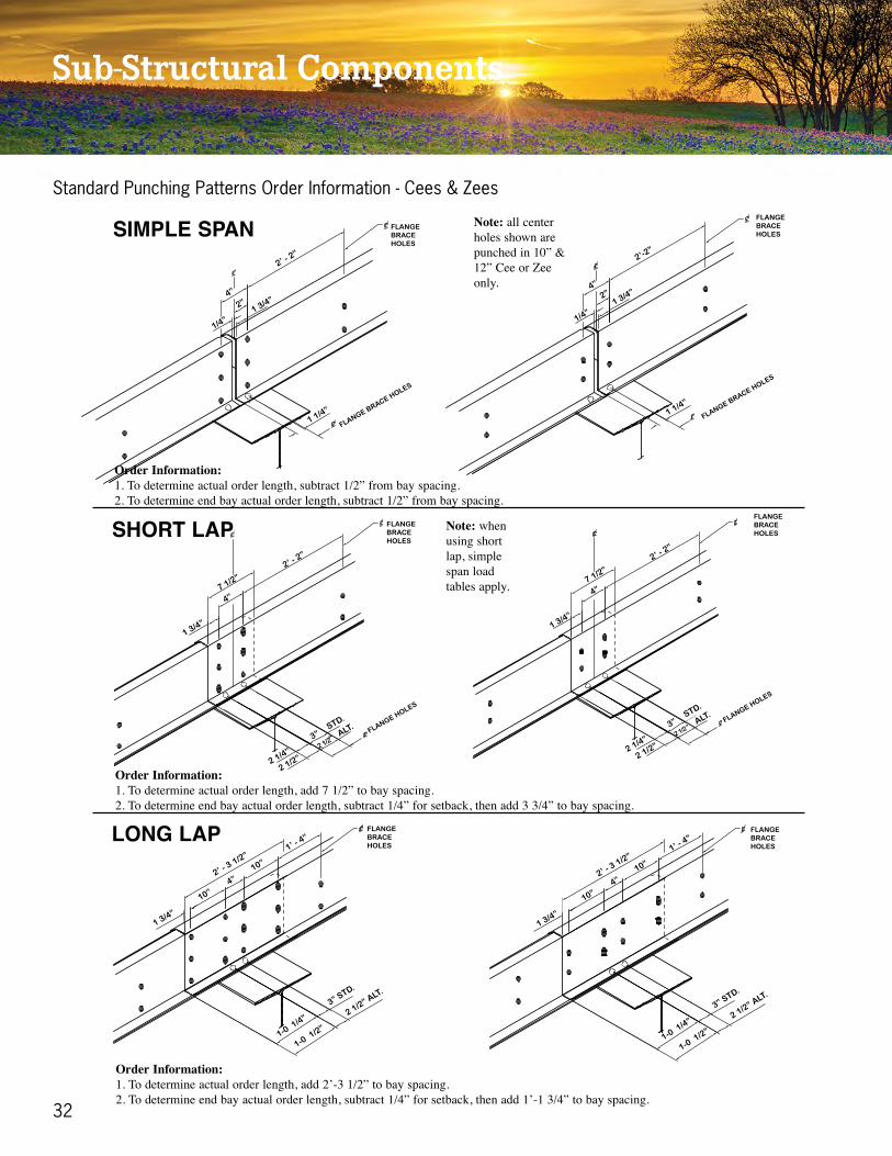
Standard Punching Patterns - Cees & Zees
32
Sub-Structural Components
Note: all centerholes shown arepunched in 10” &12” Cee or Zeeonly.
Note: whenusing shortlap, simplespan loadtables apply.
SHORT LAP
LONG LAP
SIMPLE SPAN
Order Information:1. To determine actual order length, add 2’-3 1/2” to bay spacing.2. To determine end bay actual order length, subtract 1/4” for setback, then add 1’-1 3/4” to bay spacing.
Order Information:1. To determine actual order length, add 7 1/2” to bay spacing.2. To determine end bay actual order length, subtract 1/4” for setback, then add 3 3/4” to bay spacing.
Order Information:1. To determine actual order length, subtract 1/2” from bay spacing.2. To determine end bay actual order length, subtract 1/2” from bay spacing.
1/4”
2”4”
2’ - 2”
1 3/4”
1 1/4”
FLANGEBRACEHOLES
FLANGE BRACE HOLES
1 3/4”
2 1/4”
3”STD.
ALT.
2 1/2”
2 1/2”
4”7 1/2”
2’ - 2”
FLANGEBRACEHOLES
FLANGE HOLES
1 3/4”
10”
10”
1’ - 4”
2’ - 3 1/2”
1-0 1/2”
1-0 1/4”
3” STD.
2 1/2” ALT.
4”
FLANGEBRACEHOLES
1 3/4”
10”
10”
1’ - 4”
2’ - 3 1/2”
1-0 1/2”
1-0 1/4”
3” STD.
2 1/2” ALT.
4”
FLANGEBRACEHOLES
1 3/4”
2 1/4”
3”STD.
ALT.
2 1/2”
2 1/2”
4”7 1/2”
2’ - 2”
FLANGEBRACEHOLES
FLANGE HOLES
1/4”
2”4”
2’-2”
1 3/4”
1 1/4”
FLANGEBRACEHOLES
FLANGE BRACE HOLES
Standard Punching Patterns Order Information - Cees & Zees

www.sawyermetal.com 33
Order Information:1. To determine actual order length, add 6’-3 1/2” to bay spacing.2. To determine end bay actual order length, subtract 1/4” for setback, then add 3’-1 3/4” to bay spacing.
SUPER LAP
MAX LAP
Order Information:1. To determine actual order length, add 4’-3 1/2” to bay spacing.2. To determine end bay actual order length, subtract 1/4” for setback, then add 2’-1 3/4” to bay spacing.
1 3/4”
1’-10”
1’-10”
4”
4”
4’-3 1/2”
2’-0 1
/2”2’-0
1/4”
3” STD.
2 1/2” ALT.
FLANGE BRACE HOLES
1 3/4”
2’-10”
2’-2”
2’-2”
2’-10”
4”6’-3
1/2”
3’-0 1
/2”3’-0
1/4”
3” STD.
2 1/2” ALT.
FLANGE BRACEHOLES
LAP HOLES
1 3/4”
2’-10”
2’-2”
2’-2”
2’-10”
4”6’-3
1/2”
3’-0 1
/2”3’-0
1/4”
3” STD.
2 1/2” ALT.
FLANGE BRACEHOLES
LAP HOLES
1 3/4”
1’-10”
1’-10”
4”
4”
4’-3 1/2”
2’-0 1
/2”2’-0
1/4”
3” STD.
2 1/2” ALT.
FLANGE BRACE HOLES
Standard Punching Patterns Order Information - Cees & Zees
NOTES:

34
Sub-Structural Components
* LONG LAP PUNCH
"4/31 "01 "0 "1 4'1"4
"4/3 "1 2'2"4
* SHORT LAP PUNCH
* SIMPLE SPAN PUNCH
"4/3 "1 2'2
Punching Information

www.sawyermetal.com 35
"4/3 "1 01' "1 "4 01' "1 4
"4/31 " "8 2' "2 "4 2' "2 8
* SUPER LAP PUNCH
* MAX LAP PUNCHPunching Information
* Holes shown are for members less than 10” in depth.
* UNIVERSAL PUNCH
Includes: Simple Span, Short Lap, and Long Lap
"4/31 "4 "6 "4 "01 "4 "01
"2
* STANDARD PUNCH
Includes: Max Lap and Long Lap
"4/31 "01 "4 " "8 2'1 "8 "4
"2 "2
Includes: Max Lap and Short Lap
"4/31 "4 "6'1 "4 "4 "6'1 "4
* END BAY PUNCH

36
Sub-Structural Components
* UNIVERSAL PUNCH
Includes: Simple Span, Short Lap, and Long Lap
"4/31 "4 "6 "4 "01 "4 "01
"2
* STANDARD PUNCH
Includes: Max Lap and Long Lap
"4/31 "01 "4 " "8 2'1 "8 "4
"2 "2
Includes: Max Lap and Short Lap
"4/31 "4 "6'1 "4 "4 "6'1 "4
* END BAY PUNCH* UNIVERSAL PUNCH
Includes: Simple Span, Short Lap, and Long Lap
"4/31 "4 "6 "4 "01 "4 "01
"2
* STANDARD PUNCH
Includes: Max Lap and Long Lap
"4/31 "01 "4 " "8 2'1 "8 "4
"2 "2
Includes: Max Lap and Short Lap
"4/31 "4 "6'1 "4 "4 "6'1 "4
* END BAY PUNCH
Combination Punching
* EXTENDED PUNCH
Includes: Super Lap and Max Lap
"4/31 "8 "2'1 "4 "8 "4 "01 "4 "0'1 "8
* CLASSIC PUNCH / PATTERN A
Includes: Simple Span, Short Lap, Long Lap, and Max Lap
"4/31 "4 "4 "8 " "4 8 "4"2"2
"6 6" "4
Includes: Simple Span, Short Lap, Long Lap, Max Lap, and Super Lap
"4/31 "4 "4 "4 "8 "4 "4 "8 "4" "2 2
"2
"8 "4 "4 "4"2"2"2
* COMPREHENSIVE PUNCH / PATTERN B

www.sawyermetal.com 37
* EXTENDED PUNCH
Includes: Super Lap and Max Lap
"4/31 "8 "2'1 "4 "8 "4 "01 "4 "0'1 "8
* CLASSIC PUNCH / PATTERN A
Includes: Simple Span, Short Lap, Long Lap, and Max Lap
"4/31 "4 "4 "8 " "4 8 "4"2"2
"6 6" "4
Includes: Simple Span, Short Lap, Long Lap, Max Lap, and Super Lap
"4/31 "4 "4 "4 "8 "4 "4 "8 "4" "2 2
"2
"8 "4 "4 "4"2"2"2
* COMPREHENSIVE PUNCH / PATTERN B
Combination Punching * Holes shown are for members less than 10” in depth.
* PATTERN G
1 1

38
Sub-Structural Components
LAP
LAP
LAP
For 6” thru 9” Deep Zees, 6Bolts required per Lap.
Bolts: 1/2” Diameter
For 10” thru 12” Deep Zees,8 Bolts required per Lap.
Alternate for 10” Deep Zees,8 Bolts required per Lap.
Bolts Per Lap Type - Bolts = 1/2” Diameter
www.sawyermetal.com 39
12 x 4 12 7.48 •
12 x 3 1/2 12 7.12 12 x 3 1/8 x 3 3/8 • •
12 x 3 14 4.51 12 x 2 5/8 x 2 7/8 • •
12 x 3 12 6.77 12 x 2 5/8 x 2 7/8 • •
12 x 2 1/2 14 4.27 12 x 2 1/8 x 2 3/8 • •
12 x 2 1/2 12 6.41 12 x 2 1/8 x 2 3/8 • •
10 x 4 14 4.51 •
10 x 4 12 6.77 •
10 x 3 1/2 14 4.27 10 x 3 1/8 x 3 3/8 • •
10 x 3 1/2 12 6.41 10 x 3 1/8 x 3 3/8 • •
10 x 3 14 4.03 10 x 2 5/8 x 2 7/8 • •
10 x 3 12 6.05 10 x 2 5/8 x 2 7/8 • •
10 x 2 1/2 16 3.20 10 x 2 1/8 x 2 3/8 • •
10 x 2 1/2 14 3.80 10 x 2 1/8 x 2 3/8 • •
10 x 2 1/2 12 5.69 10 x 2 1/8 x 2 3/8 • •
10 x 2 16 3.00 •
10 x 2 14 3.56 •
10 x 2 12 5.34 •
8 x 4 14 4.03 •
8 x 4 12 6.05 •
8 x 3 1/2 16 3.20 8 x 3 1/8 x 3 3/8 • •
8 x 3 1/2 14 3.80 8 x 3 1/8 x 3 3/8 • •
8 x 3 1/2 12 5.69 8 x 3 1/8 x 3 3/8 • •
8 x 3 16 3.00 8 x 2 5/8 x 2 7/8 • •
8 x 2 14 3.08 •
8 x 2 12 4.62 •
6 x 3 1/2 16 2.80 6 x 3 1/8 x 3 3/8 • •
6 x 3 1/2 14 3.32 6 x 3 1/8 x 3 3/8 • •
6 x 3 1/2 12 4.98 6 x 3 1/8 x 3 3/8 • •
6 x 3 16 2.60 6 x 2 5/8 x 2 7/8 • •
6 x 3 14 3.08 6 x 2 5/8 x 2 7/8 • •
6 x 3 12 4.62 6 x 2 5/8 x 2 7/8 • •
6 x 2 1/2 16 2.40 6 x 2 1/8 x 2 3/8 • •
6 x 2 1/2 14 2.84 6 x 2 1/8 x 2 3/8 • •
6 x 2 1/2 12 4.27 6 x 2 1/8 x 2 3/8 • •
4 x 2 1/2 16 2.00 4 x 2 1/8 x 2 3/8 • •
4 x 2 1/2 14 2.37 4 x 2 1/8 x 2 3/8 • •
4 x 2 1/2 12 3.55 4 x 2 1/8 x 2 3/8 • •
4 x 2 16 1.79 4 x 2 x 2 • •
4 x 2 14 2.13 4 x 2 x 2 • •
4 x 2 12 3.20 4 x 2 x 2 • •
SECTION GA.WTPER
LINEALFT.
AVAILABILITY
ZEES CEES
ACTUALDIM.
(LGSI ZEES)SECTION
AVAILABILITY
ZEES CEES
ACTUALDIM.
(LGSI ZEES)GA.
8 x 3 14 3.56 8 x 2 5/8 x 2 7/8 • •
8 x 3 12 5.34 8 x 2 5/8 x 2 7/8 • •
8 x 2 1/2 16 2.80 8 x 2 1/8 x 2 3/8 • •
8 x 2 1/2 14 3.32 8 x 2 1/8 x 2 3/8 • •
8 x 2 1/2 12 4.98 8 x 2 1/8 x 2 3/8 • •
8 x 2 16 2.60 •
WTPER
LINEALFT.
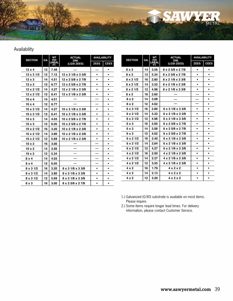
Availability
1.) Galvanized (G-90) substrate is available on most items. Please inquire.
2.) Some items require longer lead times. For delivery information, please contact Customer Service.

40
Terms & Conditions of Sale1. All references to Sawyer Metal refer to F.E. Sawyer Building Systems, Inc. D/B/A Sawyer Metal. All references to Seller refer to Sawyer Metal.
2. The parties expressly agree that none of the following Terms and Conditions of Sale, nor any Seller written terms not contained herein, may be waived, modified, or amended without the express written consent of the Seller’s President or Executive Vice-President and CFO.
3. Payments due Seller under the terms of this sale and any other money due Seller by Buyer shall be paid to Seller at its principal office in Tyler, Smith County, Texas unless otherwise directed by Seller. The laws of the State of Texas shall govern this agreement and performance under this agreement. Buyer consents to jurisdiction in Texas. Any dispute under this agreement shall only be brought in the state court of Texas. The parties hereto agree that venue shall be in Tyler, Smith County, Texas, for any and all claims or disputes arising out of all transactions between Seller and Buyer. Buyer voluntarily agrees that Tyler, Smith County, Texas, is the most convenient forum and understands the choice of forum is an integral and vital part of Seller’s agreement to sell to Buyer. By agreeing to venue in Tyler, Smith County, Texas, Buyer fully intends to waive its rights, if any, to venue in any place other than Tyler, Smith County, Texas. The parties deem that this agreement is performable in Tyler, Smith County, Texas, regardless of whether or not any part of the agreement is actually performed in Tyler, Smith County, Texas. In addition, Buyer agrees that Seller’s prices reflect an analysis of the elimination of uncertainty regarding the jurisdiction for any dispute. EACH PARTY HEREBY AGREES NOT TO ELECT A TRIAL BY JURY OF ANY ISSUE TRIABLE BY JURY AND FULLY WAIVES ANY RIGHT TO TRIAL BY JURY TO THE EXTENT THAT ANY SUCH RIGHT NOW OR HEREAFTER EXISTS WITH RESPECT TO THIS AGREEMENT AND/OR THE AGREEMENTS, INSTRUMENTS AND DOCUMENTS CONTEMPLATED HEREBY OR ANY CLAIM, COUNTER CLAIM, OR OTHER ACTION ARISING IN CONNECTION HEREWITH. EACH PARTY ACKNOWL-EDGES AND AGREES THAT IF THIS WAIVER OF RIGHT TO TRIAL BY JURY IS GIVEN KNOWINGLY AND VOLUNTARILY BY SUCH PARTY AND IS INTENDED TO ENCOMPASS EACH INSTANCE AND EACH ISSUE AS TO WHICH THE RIGHT TO TRIAL BY JURY WOULD OTHERWISE ACCRUE. EITHER PARTY IS HEREBY AUTHORIZED TO FILE A COPY OF THIS SECTION IN ANY PROCEEDING AS CONCLUSIVE EVIDENCE OF THIS IRREVOCABLE WAIVER. If Buyer purchases a Metal Building System only, the terms and conditions of this purchase order shall also be governed in their interpretation by the section titled “Common Industry Practices: from the Low Rise Building System Manual, latest edition, published by the Metal Building Manufacturers Association, 1230 Keith Building, Cleveland, Ohio, 44115.
4. Buyer agrees that all payments with lien release language on the back of any check shall be sent only to the principal office of Seller, in Tyler, Smith County, Texas. Buyer agrees that any payment accepted through Seller’s lockbox with lien release language on the check does not bind Seller to the attempted release. Seller’s agent at the lock box who endorses and/or accepts checks for Seller is authorized only to unconditional payments, and no action by this agent shall ever give rise to a claim of any authority, apparent or otherwise, beyond that described in this paragraph. Acceptance of any conditional check, including any lien release language or otherwise at the lock box shall only be a partial release for those funds received and never otherwise. This paragraph cannot be waived or modified except in writing in advance.
5. Terms of sale are C.O.D. unless otherwise agreed to in writing. Any and all credit terms shall be established at the sole discretion of Seller’s Credit Department. In the event Seller grants Buyer credit terms, said credit terms are subject to change at any time, for any reason, at the sole discretion of Seller without prior written notice to Buyer. Unless specifically enumerated herein, the price does not include any taxes (including excise, privilege, occupation, use, sales, etc.; Federal, State or local) or costs of shipment. All materials sold hereunder shall be in substantial compliance with Buyer’s request. Additionally, all materials sold hereunder are sold F.O.B. Seller’s plant. Seller reserves the right to approve the carrier on all C.O.D. shipments. Buyer assumes responsibility for the accuracy of verbal orders unless written confirmation is received prior to fabrication. Confirming orders should be marked “Confirming Order-Do Not Duplicate.”
6. Any payments deferred after the due date as specified herein shall bear interest at the rate of ten percent (10%) per annum. If an invoice becomes past due, is placed in the hands of any attorney for collection, if collected by any legal proceedings, or if the Agreement is relevant to any other dispute between the parties, Buyer agrees to pay Seller all of its attorney’s fees and costs incurred in the collection of sums owed by Buyer to Seller on account of principal, interest or other charges. Buyer agrees that the attorney’s fees incurred by Seller are reasonable and necessary. “Costs incurred in the collection of sums” as used herein is not to be limited to costs incurred in litigation, but includes, without limitation, copying and mailing expenses, lien fees, lost employee time, inspection expenses and expert witnesses expenses in addition to taxable costs incurred in litigation.
7. Buyer has and does by these presents grant to Seller and Seller has and does hereby retain a security interest in all materials, parts and accessories (as well as all finished goods and/or the proceeds from the sale thereof) described in and being purchased by Buyer pursuant to this Agreement. In addition, Buyer has and does by these presents grant to Seller and Seller has and does hereby retain a security interest in all existing or subsequently arising accounts, accounts receivable and supporting obligations which may from time to time hereafter come into existence during the term of this security interest as a result of Buyer’s sale of any of the said materials, parts, accessories, or finished goods thereof to any third party. The security interest herein granted by Buyer and retained by Seller is to secure payment of the full purchase price and all other charges due and owing Seller by Buyer under the terms of this sale. This agreement is governed by Section 2.101, et. Seq. of the Texas Business & Commerce Code, and the security interest hereunder constitutes a “purchase money security interest” pursuant to the Uniform Commercial Code. This instrument is a contract, security agreement and financing statement between the parties hereto.
8. The Buyer or undersigned individual who is either the credit applicant or a principal/agent of the Buyer, recognizes that a credit history report may be a factor in the evaluation of the credit history of the Buyer. Buyer, therefore, consents to and authorizes the use of a commercial, consumer or any other credit report on the Buyer or undersigned individual by Seller from time to time as may be needed in the credit evaluation process.
9. All orders are subject to approval and acceptance by Seller. Terms contained within any Purchase Order issued by Buyer conflicting with these Terms and Conditions shall be of no force and effect. All sales by Seller of any nature to Buyer shall be made under the provisions of this Agreement. Any documents that Buyer may use from time to time for their convenience, including but not limited to, purchase orders or sales acknowledgment forms shall be deemed to be for administrative convenience only and the terms and conditions of this Agreement as well as the terms and conditions as stated in Seller’s invoices and bills of lading shall supersede and take precedence over any of Buyer’s terms and conditions which may be contained on any such forms.
10. Seller shall not be liable to Buyer for any incidental, special, compensatory, consequential, expectation, exemplary or liquidated damages of any nature. Additionally, Seller shall not be liable to Buyer for back charges or loss of use to Buyer arising out of any alleged misfabrications or delay in carrying out this contract.
11. Under no circumstances shall Seller be liable in any way to Buyer, building owner, or any other party for water intrusion or the existence of moisture occurring prior to delivery of Seller’s material or existing thereafter or any possible effects resulting there from (including fungi, mold or mildew), delays, failure in performance, or loss or damage due to force majeure conditions including, without limitation: fire; flood; epidemics; lightening; strike; embargo; explosion; power surge or failure; acts of God; war; labor or employment disputes; civil disturbances; acts of civil or military authority; inability to secure materials, fuel, products or transportation facilities; terrorism; act of government, inability to obtain materials; loss, damage or delay of materials; acts or omissions of suppliers; or any other causes beyond Seller’s control, whether or not similar or relating to the foregoing. FURTHER, BUYER HEREBY AGREES AND STIPULATES THAT, IN THE EVENT SELLER RECEIVES NOTIFICATION OF A SCHEDULED PRICE INCREASE(S) FROM ANY OF ITS SUPPLIERS BETWEEN THE DATE OF THIS AGREEMENT AND THE DATE SCHEDULED FOR DELIVERY OF THE MATERIALS COVERED HEREBY, SELLER RESERVES THE RIGHT, IN ITS SOLE DISCRETION AND JUDGMENT, TO INCREASE THE PURCHASE PRICE STATED HEREIN IN AN AMOUNT CORRESPONDING TO SAID PRICE INCREASE(S). Buyer agrees these limitations of Seller’s liability are reasonable. Buyer further agrees that these limitations of Seller’s liability are material parts of the consideration for this Agreement and is reflected in the amounts charged by Seller hereunder. Buyer intends that these limitations on Seller’s liability are to be liberally construed in favor of Seller to eliminate any other liability of Seller other than repair or replacement of defective products.
12. Either party may cancel an order by giving written notice to the other party. In the event of such cancellation, Buyer agrees to pay Seller all costs and damages incurred by Seller in preparing to perform the terms of the order and in performing the terms of the order prior to the receipt by Seller of such written notice, including but not limited to Seller’s expenses of purchases of material, labor, fabrication and overhead.
13. All materials sold hereunder to Buyer are final and cannot be returned to Seller for credit unless Buyer obtains prior written approval from Seller’s authorized representative. A 25% restocking fee shall be charged on all returned materials. Buyer may arrange for pickup of order at Seller’s plant or shipment will be made by common carrier - “Freight Collect” - unless other arrangements are previously made. If, at Buyer’s request, the delivery of materials is delayed, then Seller shall have the option to invoice Buyer for the price of materials, which invoice shall be due in accordance with the terms of payment provided herein. Buyer will reimburse Seller for the cost of storing materials if shipment is delayed by Buyer, and will assume any damages to the materials caused by deterioration.
14. Upon receipt of payment in full, Seller warrants its workmanship only against failure due to defective material or workmanship for a period of one (1) year from date of manufacture; however, Buyer’s sole and exclusive remedy shall be limited to the repair or replacement of defective part(s), F.O.B. Seller’s plants (transportation, redesign, dismantling, disposal of material and installation are not included and shall be borne and paid for by Buyer). Any such replacement or repair shall not include any materials not sold by Seller hereunder, and specifically excludes any obligation by Seller related to other property of the Buyer or any property of third parties. UNDER NO CIRCUMSTANCES SHALL SELLER BE RESPONSIBLE OR LIABLE TO BUYER, OWNER(S) OR ANY THIRD PARTY, IN ANY RESPECT FOR, AND SELLER HEREBY EXPRESSLY DISCLAIMS ANY AND ALL WARRANTIES OR REPRESENTATIONS PERTAINING TO, PRESENT OR FUTURE WATER LEAKS, OR MOISTURE INTRUSION(S), DAMAGE(S), TO THE BUILDING(S), OR ANY COMPONENTS OR CONTENTS THEREOF, OR ANY INTERIOR SPACE(S) OR PROPERTY THEREIN, INCLUDING CLAIMS PERTAINING TO MOLD, MILDEW OR FUNGI, OR INTERRUPTION IN THE USE OF THE BUILDING(S) OR PERSONAL INJURY OR PROPERTY DAMAGE CLAIMS RESULTING FROM THE ALLEGED EXISTENCE OR GROWTH OF MOLD, MILDEW AND/OR FUNGI. As a condition precedent to the effectiveness of any warranty provided herein, all amounts due and owing to Seller under this or any other agreement with SELLER or Seller’s affiliates, whether disputed or not by Buyer, must be fully paid. Seller’s sole liability, if any, to Buyer shall be strictly limited to the written express warranties specified herein, and Buyer agrees and stipulates that Seller shall not be liable for any incidental, consequential, liquidated, exemplary or punitive damages, which Buyer may allegedly suffer for any reason, including reasons attributable to Seller. Seller does not warrant any products or materials that are not manufactured by Seller except to the extent of the warranty Seller may actually pass through or assign from the manufacturer. EXCEPT AS STATED ABOVE, SELLER HEREBY EXPRESSLY DISCLAIMS ALL WARRANTIES, EXPRESS OR IMPLIED, INCLUDING, WITHOUT LIMITATIONS, THE IMPLIED WARRANTIES OF MERCHANTABILITY OR FITNESS FOR A PARTICULAR PURPOSE, AND THE PARTIES HERETO HEREBY STIPULATE THAT ALL SUCH WARRANTIES ARE HEREBY DISCLAIMED. Buyer acknowledges, agrees, and stipulates that oil-canning of materials shall not be a cause of rejection of materials. Claims for shortages or defective materials must be made to Seller in writing within five (5) days after delivery of shipment (which the Parties agree is a reasonable time), or any and all such claim(s) shall by conclusively waived and released by Buyer. Notwithstanding the foregoing, installation of materials shall unequivocally constitute irrevocable acceptance of said materials.
15. Any plans, specifications, details, descriptions, documents, terms and/or conditions not specifically referred to and accepted in this agreement are not a part hereof and shall not binding upon Seller. If requested, Seller will submit to Buyer approval drawings of the materials and/or Metal Building System which is the goods forming the subject matter of this contract. The approval drawings may consist of a floor plan, anchor bolt plan and cross section. In order for Seller to proceed with the preparation of detailed shop drawings and the manufacture of the materials, the Buyer shall return one (1) set of approval drawings to the Seller with a notation of the Buyer’s outright approval subject to changes or corrections, if any, noted thereon. Approval as noted by the Buyer affirms that Seller has correctly interpreted the overall contract requirements for the materials and/or Metal Buildings Systems and its accessories, and the exact location of accessories. All material sold will be in sub-stantial compliance to approved drawings only. Buyer may orally waive the right to receive and approve drawings; provided, however, that in waiving such right, Buyer accepts Seller’s interpretation as being correct and further accepts all responsibility for any discrepancies in the materials and/or Metal Building System that a review of the said drawings would have revealed to Buyer. Detailed shop drawings of individual parts of the material or Metal Building System will not be furnished by Seller.
16. Buyer may submit a written request for change orders to Seller adding, deleting or altering the Quantity, Description or Specifications of material ordered. Seller, upon receipt of a written request for change order, shall price the requested changes and send to Buyer a price quotation thereof. Seller shall be under no obligation to accept or perform a request for change order unless Buyer accepts in writing, without alteration or adjustment, the change order at the prices and terms quoted by Seller.
17. BUYER ASSUMES ENTIRE RESPONSIBILITY AND LIABILITY FOR ANY CLAIMS OR ACTIONS BASED ON OR ARISING OUT OF INJURIES, INCLUDING DEATH, TO PERSONS OR DAMAGES TO OR DESTRUCTION OF PROPERTY (WHETHER BELONGING TO BUYER, BUILDING OWNER, AND/OR ANY THIRD PARTY), SUSTAINED OR ALLEGED TO HAVE BEEN SUSTAINED IN CONNECTION WITH OR TO HAVE ARISEN OUT OF OR INCIDENTAL TO THE PERFORMANCE OF THIS CONTRACT BY BUYER, ITS AGENTS AND EMPLOYEES, AND ITS SUBCONTRACTORS, THEIR AGENTS AND EMPLOYEES, INCLUDING CLAIMS OR ACTIONS FOUNDED IN WHOLE OR IN PART UPON THE ALLEGED ACTS, OMISSIONS, NEGLIGENCE OR FAULT OF SELLER, SELLER’S REPRESENTATIVES, OR THE EMPLOYEES, AGENTS, INVITEES, OR LICENSEES THEREOF. BUYER FURTHER AGREES TO DEFEND, INDEMNIFY AND HOLD HARMLESS SELLER AND ITS REPRESENTATIVES, AND THE EMPLOYEES, AGENTS, INVITEES AND LICENSEES THEREOF IN RESPECT OF ANY SUCH MATTERS AND AGREES TO DEFEND ANY CLAIM OR SUIT OR ACTION BROUGHT AGAINST SELLER, SELLER’S REPRESENTATIVE, AND THE EMPLOYEES, AGENTS, INVITEES AND LICENSEES THEREOF. THE PARTIES HEREBY WAIVE THEIR RESPECTIVE RIGHTS UNDER THE DECEPTIVE TRADE PRACTICES-CONSUMER PROTECTION ACT, SECTIONS 17.41 THROUGH 17.63 INCLUSIVE, OF THE TEXAS BUSINESS AND COMMERCE CODE, A LAW THAT GIVES CONSUMERS SPECIAL RIGHTS AND PROTECTIONS. AFTER CONSULTATION WITH LEGAL COUNSEL, EACH VOLUNTARILY CONSENTS WITH THIS WAIVER.
18. This Agreement, along with Seller’s store policies and any attached exhibits, constitutes the entire agreement of the parties herein.

Warranty InformationThe only warranties available are those issued in writing by the manufacturer and no other warranties either implied or expressed are to be considered.
PLEASE NOTE: Actual colors may vary from the sample swatches shown. These colors may not match those of other companies despite color names being identical.
Different paint systems may have slightly different color shades between systems even though the color name is the same.
Film thickness on 40-Year SMP painted material is 1.0 mils nominal (± 0.2 mils) on the finish colors, 0.5 mils nominal (± 0.1 mils) on the reverse side. Both thicknesses are inclusive of the primer.
Film thickness on 10-Year & Non-Warranties material is 0.8 mils nominal (± 0.2 mils) on the finish color, 0.5 mils nominal (± 0.1 mils) on the reverse side. Both thicknesses are inclusive of the primer.
Non-Warrantied panels are sold (AS IS) with possible imperfections and are not rejectable.
All painted material has an Off-White, Non-Warrantied, straight polyester wash coat on the reverse side. Reverse side shades may vary but this is not a cause for rejection.
These COLOR NAME PREFIXES will be used to identify the PAINT SYSTEMS shown:NW = Non-Warrantied Polyester, POLY = 10-Year Polyester, SMP = 40-Year Siliconized Polyester.
Manufacturing American Quality – with Texas Pride
Mon - Thurs - 8am - 5pm, Fri - 8am - 4:30pm12562 State Hwy 64W - Tyler, TX (1.8 miles from Loop 323 toward airport)
903.531.0182 • FAX: 903.531.2402 • www.sawyermetal.com

R7/17


