35


CONTENTS
Introduction _______________________________________________ 3Features ____________________________________________________ 3Setup ________________________________________________________ 5JOG/slew Mode ______________________________________________ 6Digitizing _________________________________________________ 7On-Line Mode _______________________________________________ 7Command Summary____________________________________________ 8Example Programs __________________________________________ 9Interactive Mode _________________________________________ 14Stand-alone Mode _________________________________________ 15Daisy-chaining NF90 Controllers _______________________ 16Reference __________________________________________________ 18
I ndex Motor Command ____________________________________ 18Speed of Motor Command _________________________________ 19Acceleration/deceleration Command ______________________ 20Loop Commands __________________________________________ 20Pause Command __________________________________________ 21User Commands __________________________________________ 21Backlash Compensation Command __________________________ 23Indicate Over-travel Command ___________________________ 23Quit On-Line Mode Command ______________________________ 24Run Command ____________________________________________ 24Null Position Registers Command ________________________ 24Kill Operation Command _________________________________ 24Verify Controller’s Status Command _____________________ 24Clear Memory Command ___________________________________ 24Decelerate to a Stop Command ___________________________ 25Enable On-Line Mode Command ____________________________ 25Enable On-Line Mode with Echo o FF Command ______________ 25Go after Waiting or Holding Command ____________________ 25Put Controller on Hold Command _________________________ 25<Delete > Command _______________________________________ 25Request Motor Position Commands ________________________ 26Commands for Daisy-Chained Controllers _________________ 26
Troubleshooting Procedure _______________________________ 27Specifications ____________________________________________ 29
Appendix ASwitch settings and RS-232-C Connections ____________________ 30Appendix BLimit Switch and Joystick Connections _______________________ 31Appendix CUSER OUT, USER IN, and RUN Connections ______________________ 32Appendix DMotor Connections ___________________________________________ 33Appendix EMotor Performance ___________________________________________ 34
2

Introduction
The NF90 is a programmable stepping motor controller forrunning up to three motors, one-at-a-time. The Controllerincorporates a single chip "Super Microprocessor" that has on-chipRAM. The RAM is available for temporary storage of a user-enteredprogram and motion parameters.Commands and data are entered through the RS-232-C interface froma host computer, terminal, or programmable controller. SpecializedCommands provide simple and efficient entry of a complex, yetcompact, program.
Features
Completely wired and tested for direct connection to UniSlidemotors/ assemblies.
A complete microprocessor-based Controller with motor drivesfor three motors.
400 steps per revolution (0.9 o step angle) resolution
Output current is factory matched for a specific motor (0.7 to4.7 amp/phase motor).
An all metal enclosure and Linear type motor and logic powersupplies result in low RFI and EMI.
95-130 VAC, 50/60 Hz operation. 190-260 VAC, 50/60 Hzoperation with European fuses is available.
JOG/slew mode allows motors to be jogged one step or slewed upto 1000 steps/sec. or 2000 steps/sec.(switch settable). Anoptional joystick is available.
A Digitizing function can be utilized with a host terminalconnected as a readout of motor position.
A three wire serial port, conforming to EIA standard RS-232-C,allows a host to enter Commands (ASCII characters) and Data,Poll for status, and Read Position information.
The NF90 will run in an interactive or stand-alone mode.
Acceleration/Deceleration settable from 2,000 to 100,000steps/sec 2 in 2,000 step/sec 2 increments.
Speed programmable from 1 to 6000 steps/sec in 1 step/secincrements. NOTE: Most motors have low torque above 2000steps/sec. (see speed/torque curves in Appendix E)
Incremental Index distance is programmable from ±1 to±1,048,575 steps.
3

Programmable Return-to-Zero position.
Six powerful Loop Commands provide from one to continuousrepeat operations, performing simple functions likeauto-reverse to raster scans and other complex X,Y matrixpatterns.
Programmable pauses from 100 milliseconds to 13 minutes.
A User Output can be programmed to turn On and Off an externalsolid state relay, or interface to other logic level devices.
A User Input can be utilized in a program as a Wait forexternal switch or relay closure.
Backlash Compensation can be set to automatically finish everyindex approaching from the positive direction.
Run, Limit switch, Joystick, Output, Input, RS-232-C, andMotor connections are accessible at unpluggable connectors onthe front panel.
RS-232-C baud rate settings are switch settable to 300, 1200,4800, or 9600.
As many as 255 controllers can be "daisy-chained" togetherallowing the host to address each one from just one serialport.
Limit Switches for CW and CCW directions are provided withplug-in connection to UniSlide limit switch assemblies.Limits can be used for "homing."
Automatic Power Down reduces power consumption byde-energizing the motors when at a standstill.
Single Step mode is provided for debugging a program or as acontrolled interrupt.
The NF90 can be polled for its status at any time;additionally a prompt ("^") is automatically sent to the hostwhen a program has finished.
The NF90 can be programmed to send a pulse or character atpreset distances without stopping or slowing the motor.
Motor position can be read while motor is in motion ( up to500 steps/sec. )
The NF90 can be set to signal the host when a limit switch hasbeen encountered.
Terminal, Diagnostic, and Example programs for MS-DOS PCs ona diskette are included.
4

Setup
* * CAUTION * ** HAZARDOUS VOLTAGE, DO NOT REMOVE CONTROLLER’S COVER* DO NOT CONNECT OR DISCONNECT MOTOR(S) WHEN POWER IS "ON"* HIGH TEMPERATURE, NF90 SHOULD BE KEPT AT LEAST
6 INCHES FROM ANY OBJECTS* AIR MUST CIRCULATE AROUND THE CONTROLLER* NEVER USE IN AN EXPLOSIVE ENVIRONMENT* IN INDUSTRIAL ENVIRONMENTS, THE NF90 MUST BE PROTECTED TO
PREVENT METAL CHIPS FROM GETTING INTO SMALL OPENINGS
NF90 controllers are factory wired with 8 foot cables for motor(s)and limit switch(es). An optional joystick or RS-232-C cable willbe factory wired to the NF90.
CAUTION: Before connecting motor(s), compare the motor’s labelcurrent and the resistor ohms value from the label on the back ofthe NF90 to the following table:
NF90 Resistor( 100 watt wirewound, located in screened
channel on back of NF90, see Appendix Dfor electrical connection )
2Ω 3Ω 4Ω 5Ω 7Ω 10Ω
Motor(Amps) 2.9-4.7 2.8-3.8 1.9-2.9 1.5-1.9 1.2-1.4 0.7-1.1
DANGER: The motor current/resistor combination must be within thelimits of the above table. A mismatch of motors to resistor valuecan result in severe damage to controller or motors.
Refer to Appendix A and B to determine proper RS-232-C andjoystick connections to the NF90.
1. Connect cables to motors and limit switches. Connect a cablebetween your computer’s or terminal’s serial port and the NF90.
IMPORTANT: Limit Switch inputs require a closed circuit for themotor(s) to operate, ie, for motors to operate, limit switch cablesmust be connected to the UniSlide limit assemblies or equivalent(see Appendix B).
5

2. The NF90 is factory set to 9600 baud, 7 data, 2 stop bits, andeven parity. To change baud rate refer to Appendix A.
CAUTION: Never connect or disconnect motors with power on; thismay result in severe damage to motor drives.
3. Plug the NF90 into a 120VAC outlet.
4. Turn on the NF90 by pushing the top of the rocker switchlocated on the back panel.
The Power light will come on and the On-Line light will flash onthen off once.
The NF90 is now ready to receive commands or be jogged/slewed fromthe optional joystick or user inputs to the JOG inputs (seeAppendix B).
The simplest method to send commands (ASCII characters) to the NF90is with a terminal or computer operating with a terminal program(such as NFTERM included on the Utility Disk). Make sure yourcomputer or terminal is set at 7 data, 2 stop bits and even parity,and the same baud rate as the NF90 ( see Appendix A to change baudrate on the NF90 ).
The other method to send commands is with commercially availablelanguages such as BASIC, C, PASCAL, FORTRAN, or ASSEMBLY.
JOG/slew Mode:
When the On-Line light is not lit the NF90 is in the JOG/slew mode.
With the NF90 in the JOG/slew mode, the motors can bejogged one step, or slewed to 1000 (factory setting) or 2000steps/sec determined by the setting of SW-3 (see Appendix A).
To JOG motor 1 positive (CW), press the joystick 1+ buttonmomentarily; the motor will move one step CW. To slew the motormaintain pressure on the 1+ button; the motor will accelerate tospeed until the button is released.
To JOG motor 1 negative (CCW), press the joystick 1- buttonmomentarily; the motor will move one step CCW. To slew the motormaintain pressure on the 1- button; the motor will accelerate tospeed until the button is released.
To JOG motor 2 positive (CW), press the joystick 2+ buttonmomentarily; the motor will move one step CW. To slew the motormaintain pressure on the 2+ button; the motor will accelerate tospeed until the button is released.
6

To JOG motor 2 negative (CCW), press the joystick 2- buttonmomentarily; the motor will move one step CCW. To slew the motormaintain pressure on the 2- button; the motor will accelerate tospeed until the button is released.
To jog or slew motor 3, hold the shift * button down andactuate the joystick motor 2 buttons.
Digitizing:
The NF90 stores its absolute position (relative to the positionwhen power was applied or when registers were zeroed) in memoryuntil the NF90 is turned-off. The absolute registers reflect theaccumulated distance from operating the motors in the JOG/slew modeand/or under program control. These registers can hold from-8388608 to +8388607 steps.
With a host terminal or computer connected via the RS-232-Cinterface, the NF90 can be used as a digitizer. In the JOG/slewmode the NF90 will send motor position when it receivesa " D" from the host.Here is an example of what the host would receive when Motor 1 isat absolute 201, Motor 2 is at absolute -1294010, and Motor 3 is at0:
<lf> X+0000201 <cr><lf> Y-1294010 <cr><lf> Z+0000000 <cr>
<lf> is a linefeed, <cr> is a carriage return.The host can null ("zero") the registers by sending a " N" to theController.There is a program called "NFDISPLY" on the Utility Disk forautomatically displaying position in actual distance units forvarious lead screws and rotary tables.
On-Line Mode:
The NF90 can be programmed when it is in the On-Line mode.To put the NF90 in the On-Line mode the host must send a " E" or" F". When the controller receives an " E" or " F" the On-line lightwill light.
The " E" puts the NF90 on-line with echo "on" (echoes all charactersreceived back to the host). The " F" puts the NF90 on-line with echo"off".If you are using a terminal to communicate to the NF90 use the " E"so that the characters the controller echoes will be displayed onthe terminal screen.
* This button is designated by:
7

Command Summary:(See Reference Section for a more complete description)
The following must end with a carriage return (Enter key) or comma:I mMx Set steps to I ndex motor CW (positive), m= motor# (1,2,3), x=1
to 1048575I mM-x Set steps to I ndex motor CCW (negative), m= motor# (1,2,3),
x=1 to 1048575I mM0 Index motor to absolute zero position, m=motor# (1,2,3)SmMx Set Speed of motor, m= motor# (1,2,3), x=1 to 6000 steps/sec.AmMx Acceleration/deceleration, m= motor# (1,2,3), x=1 to 50L0 Loop continually from the beginningL-0 Sets the Loop-to-marker at the current location in the programLx Loop from beginning or Loop-to-marker x-1 times ( x=2 to 255)L- x Loop from beginning or Loop-to-marker x-1 times, alternating
direction of motor 1LM-2 L oop once from beginning or Loop-to-marker reversing index
direction of motor 2LM-3 L oop once from beginning or Loop-to-marker reversing index
direction of motor 1 and motor 2Px Pause x tenths of a second and output if output enabled ( x=0
to 8191, 10 µsec pause when x=0)U0 Wait for a "high" on the user inputU1 Wait for a high on the user input, holding the user output
high while waitingU2 Disable user output when pausingU3 Enable output when pausing (reset state)U4 User output "low"U5 User output highU6 Send "W" to host and wait for a "G" to continueU7 Start of Continuous Index with pulse outputU8 Start of Continuous Index sending "@" to the hostU9 End of Continuous IndexBx Backlash Compensation, compensation on when x=1, off when x=0Ox Indicate Limit Switch Over-travel to host, off when x=0, NF90
sends "O" when x=1 and a limit switch is encounteredThe following commands do not need the carriage return or comma:Q Quit On-Line mode (return to Jog/Slew mode)R Run programN Null (zero) motors 1,2,3 Absolute Position RegistersK Kill operation in progressV Verify Controller’s status; when On-Line, NF90 sends "B" to
host if busy, "R" if ready; in Jog/slew Mode NF90 sends "J"C Clear program from memoryD Decelerate to a stop (interrupts current index in progress)E Enable On-Line mode with echo onF Enable On-Line mode with echo o FFG Go after waiting or holdingH Put Controller on Hold (single step mode)X Send position of motor 1 to hostY Send position of motor 2 to hostZ Send position of motor 3 to hostThe following are for NF90s that are daisy-chained together:[ x ] Send commands to the next NF90 in the "chain", x are any of
the above commands& Enable multiple NF90s that are daisy-chained
8

Example Programs: (These Examples are included on the UtilityDisk)
The following examples require commands (ASCII characters) be sentto the NF90 with a terminal or computer operating with a terminalprogram. Make sure your computer or terminal is set at 7 data, 2stop bits and even parity, and the same baud rate (baud rate isfactory set to 9600) as the NF90 ( see Appendix A to change baudrate on the NF90 ).
The other method to send commands is with commercially availablelanguages such as BASIC, C, PASCAL, FORTRAN, or ASSEMBLY.
Note: The " <cr> " is a carriage return character ( <Enter> key onmost keyboards). Command characters are in LARGE BOLD.
Example #1 Motors run RAM usage Function(bytes)
On-Line - - Enable On-Line modewith echo on (On-Line light lit)
E
Example #2 Motors run RAM usage Function(bytes)
Index 1 3 Index Motor 1 400steps (1 rev) CW
I1M400,Ror
I1M400 <cr>R
→Graphic Representation: start +----+ end
Example #3 Motors run RAM usage Function(bytes)
Clear - - C l e a r p r e v i o u sprogram from memory
C
9

Example #4 Motors run RAM usage Function(bytes)
Index 1 3 Index Motor 1 600steps CCW
I1M-600,R
←end +------+ start
Example #5 Motors run RAM usage Function(bytes)
Auto-Reverse 1 6 Auto-Reverse (motor2)
I2M600,I2M0,R
→start/end +------+
: :+------+
←
Example #6 Motors run RAM usage Function(bytes)
Repeating Index 1 9 Repeating Index intwo direct ions,pausing 1 sec.between Indexes
P10,I1M400,L10,L-2,R
→P P P P P P P P P P
start/end +---+---+---+---+---+---+---+---+---+1 2 3 4 5 6 7 8 9 10: :P P P P P P P P P P+---+---+---+---+---+---+---+---+---+
10 9 8 7 6 5 4 3 2 1←
10

Example #7 Motors run RAM usage Function(bytes)
Raster Scan 2 18 Raster scan with 1sec. pauses andwaiting for input atbeginning and theend, then runbackwards throughraster scan
I1M200,P10,L7,I2M400,L-4,U0,LM-2,U0,L0,R→
start P P P P P P+-1--+-2--+-3--+-4--+-5--+-6--+-7--+ 1U P P P P P P
⇐⇑↓
←P P P P P P
+-7--+-6--+-5--+-4--+-3--+-2--+-1--+ 2P P P P P P
⇒⇑↓
→P P P P P P
+-1--+-2--+-3--+-4--+-5--+-6--+-7--+ 3P P P P P P
⇐⇑↓
←P P P P P P
+-7--+-6--+-5--+-4--+-3--+-2--+-1--+ 4U P P P P P P
⇒Key: → =forward path
⇒ =backwards path
Example #8 Motors run RAM usage Function(bytes)
Rectangle 2 12 Rectangle, wi thOutput and Wait ateach corner
I1M2000,U1,I2M1000,U1,LM-3,L0 <cr>
→ Ustart +--------------------------------+
U ↓↑U U+--------------------------------+
←
11

Example #9 Motors run RAM usage Function(bytes)
Home to Limit 1 9 Home Motor 1 toP o s i t i v e L i m i tSwitch and move 200steps from switchand zero position
S1M600,I1M1000000,I1M-200,R <cr>
The host must wait for the above commands to finish (wait for "^"from NF90) and then zero position registers and clear the abovecommands from memory by executing the following:
NC
The NF90 is now zeroed 200 steps from the positive limit switch andready for a program.CAUTION: Motor speed should not be set above 1000 steps/sec. whenhoming to a limit switch.
→start +------------------------------------- limit switch
:end +----
←
Example #10 Motors run RAM usage Function(bytes)
X,Y Matrix 2 17 Mirror-image X,YMatrix
P3,I1M-400,L3,I2M400,L-4,I1M1600,LM-3 <cr>
start/end← ←
P P P P P P1 +----+----+--------------+----+----+
3 2 1↓ → → ↑P P P P P P
2 +----+----+ +----+----+↓ ↑
← ←P P P P P P
3 +----+----+ +----+----+↓ ↑
→ →P P P P P P
4 +----+----+--------------+----+----+1 2 3
12

Example #11 Motors run RAM usage Function(bytes)
Two Raster Scans 2 19 Two Different RasterScans using Loop-to-marker
I1M2000,I2M300,L-4,L-0,I2M600,I1M3000,L-3,I2M0 <cr>→
start/end +---------------------------+ 1↑ ↓
←+---------------------------+ 2↓
→+---------------------------+ 3
↓↑ ←
+---------------------------+ 4↓
→+------------------------------------------+ 1
↓
←+------------------------------------------+ 2↓
↑
+ 3
Example #12 Motors run RAM usage Function(bytes)
X,Y Matrix 3 22 X,Y Matrix Moving ZAxis Up then Down ateach Position
I3M2000,I3M-2000,I1M1600,L5,I2M400,L-3,I1M0,I2M0 <cr>
1 2 3 4 5→ →
Z Z Z Z Zstart/end +---------+--------+--------+--------+ 1
↓↑ ←
Z Z Z Z Z+---------+--------+--------+--------+ 2↓
↑ →Z Z Z Z Z+---------+--------+--------+--------+ 3
↑ ← ← ← ←
13

Interactive Mode
The NF90 can be controlled in an interactive mode. The followingprocedure would be used for running the NF90 in an interactivemode:
1. The host puts the NF90 On-Line by sending an " F"2. The host sends a " N" to zero position registers if necessary3. The host sends speed, and acceleration if necessary4. The host sends an Index5. The host sends a " R" to start the Index6. The host then will wait until it receives a ready prompt (" ^ ")
from the NF907. The user’s routine for outputting, measuring, etc. would be
executed by the host8. A " C" would be sent from the host to clear the previous Index
command from the NF90’s memory9. The process is repeated from step # 3
Below is an interactive example written in BASIC: (This program isincluded on the Utility Disk under the name "NFEXINT")
95 REM Open RS-232 (COM1:), 9600 Baud, control lines disabled,ASCII100 OPEN "COM1:9600,E,7,2,CS0,DS0" FOR RANDOM AS #1105 REM Enable with echo off, Zero position registers110 PRINT #1, " FN"115 REM Clear any existing program, 1000 Steps/Sec, Index 1500steps120 PRINT #1, " C S1M1000,I1M1500,R "130 GOSUB 500135 REM Clear existing program, Index 900 steps140 PRINT #1, " C I1M900,R "150 GOSUB 500155 REM Clear existing program, Index 1000 steps160 PRINT #1, " C I1M1000,R "170 GOSUB 500175 REM Clear existing program, 2000 Steps/Sec, Index to zero180 PRINT #1, " C S1M2000,I1M0,R "190 GOSUB 500390 PRINT "DONE RUNNING NF90"392 REM leave NF90 off-line395 PRINT #1, " Q"400 END499 REM Wait until ready ("^") prompt appears in receive buffer500 C$ = INPUT$(1, #1)510 IF C$ <> " ^ " THEN 500515 REM Request motor position from NF90 and print on your computer520 PRINT #1, " X"530 INPUT #1, P540 PRINT "MOTOR POSITION="; P550 REM Your routine for end of Index would go here600 RETURN
14
Stand-alone Mode
The NF90 can be programmed in a stand-alone mode. In a stand-alonemode the host downloads all the commands necessary and the operatorstarts the program with the RUN (J1,4) input on the J1 connector(see Appendix C for a proper remote RUN input).
Below is a BASIC example that sends example #6 as a stand-aloneprogram: (This program is included on the Utility Disk under thename "NFEXSTD")
95 REM Open RS-232 (COM1:), 9600 Baud, control lines disabled,ASCII100 OPEN "COM1:9600,E,7,2,CS0,DS0" FOR RANDOM AS #1105 REM Enable with echo off, Zero position registers,clear any pgm110 PRINT #1, " FNC P10,I1M400,L10,L-2 ,"999 END
Another way of sending programs from an IBM PC would be to firstwrite them as text files with an editor such as DOS Edlin orWordstar nondocument, and use the DOS commands MODE and COPY tosend them to the NF90.
If the following program was stored under the file name of"EXAMPLE":
FNC P10,I1M400,L10,L-2,
Then the following DOS commands would send the program at 9600 baudto a NF90 connected to COM1 serial port of the PC:
MODE COM1:9600,E,7,2COPY EXAMPLE COM1
15

Daisy-chaining NF90 Controllers
Users that require more than three motors or simultaneous motioncan daisy-chain NF90 Controllers together. Multiple Controllers canbe operated from a single RS-232 port by daisy-chaining. Whendaisy-chaining multiple NF90s together, addressing is accomplishedby enclosing information in brackets. Information between bracketsis relayed to succeeding Controllers. The number of brackets useddetermines the destination of the information. As each Controllerreceives the information, it removes a set of brackets and relaysthe remainder of the instruction to the next Controller. Up to 255Controllers can be daisy-chained together and programmed in thismanner. For example, if four Controllers are daisy-chained togetherand the fourth Control is to be programmed, the instruction forthat Controller would be placed within three brackets. The firstController receiving the information would remove one set ofbrackets and relay the information along, the second Controllerwould remove the second set of brackets and the third Controllerwould remove the third set and relay the instructions to the fourthwithout any brackets. The targeted fourth Controller would then beprogrammed with the information.
EXAMPLES:
This character will put all the NF90s On-Line.&
This will take two NF90s linked together off-line.[Q]Q
This will program Controller #4 to Index Motor 1 800 Steps.[[[C,I1M800,R]]]
This polls Controller #2 to see if it is busy.[V]
This requests position of Motor 1 of Controller #3.[[X]]
16

The procedure for daisy-chaining Controllers:
1. Connect the RS-232 from the host to the NF90 Controllersas shown.
2. Set RS-232 parameters on the host and Controllers thesame.
3. Initialize Controllers by sending the following character( CAUTION: do not use the "E" or "F" command to put theNF90s On-Line):
&
The "&" commands all the Controllers On-Line with echooff (the host will receive a " ! " from the last NF90).
4. Controller #1 is now ready to receive commands, all othercontrollers will be in a relay mode. Use brackets toaddress a different NF90 in the chain.
17
ReferenceThis section gives detailed explanations of the NF90’s commands
The following commands must end with a carriage return (Enter keyor Return on most keyboards) or a comma. Most of the commands usethe NF90’s (RAM) memory. The required memory needed per command isspecified in the following descriptions. The NF90 has 101 bytes ofRAM available for commands, which is reestablished when the "C"(Clear) command is used. The NF90 will ignore any incomingcommands and send a "^" if it’s memory is totally full.
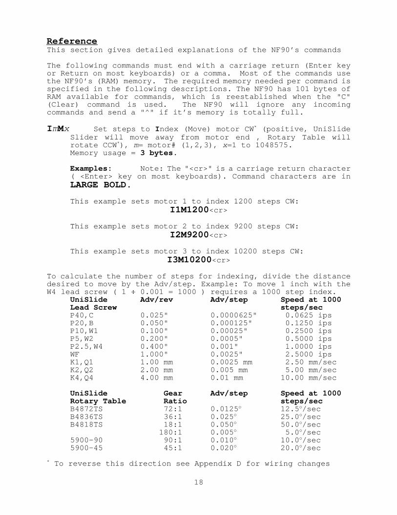
I mMx Set steps to I ndex (Move) motor CW * (positive, UniSlideSlider will move away from motor end , Rotary Table willrotate CCW * ), m= motor# (1,2,3), x=1 to 1048575.Memory usage = 3 bytes .
Examples: Note: The "<cr>" is a carriage return character( <Enter> key on most keyboards). Command characters are inLARGE BOLD.
This example sets motor 1 to index 1200 steps CW:I1M1200 <cr>
This example sets motor 2 to index 9200 steps CW:I2M9200 <cr>
This example sets motor 3 to index 10200 steps CW:I3M10200 <cr>
To calculate the number of steps for indexing, divide the distancedesired to move by the Adv/step. Example: To move 1 inch with theW4 lead scre w ( 1 ÷ 0.001 = 1000 ) requires a 1000 step index.
UniSlide Adv/rev Adv/step Speed at 1000Lead Screw steps/secP40,C 0.025" 0.0000625" 0.0625 ipsP20,B 0.050" 0.000125" 0.1250 ipsP10,W1 0.100" 0.00025" 0.2500 ipsP5,W2 0.200" 0.0005" 0.5000 ipsP2.5,W4 0.400" 0.001" 1.0000 ipsWF 1.000" 0.0025" 2.5000 ipsK1,Q1 1.00 mm 0.0025 mm 2.50 mm/secK2,Q2 2.00 mm 0.005 mm 5.00 mm/secK4,Q4 4.00 mm 0.01 mm 10.00 mm/sec
UniSlide Gear Adv/step Speed at 1000Rotary Table Ratio steps/secB4872TS 72:1 0.0125 o 12.5 o/secB4836TS 36:1 0.025 o 25.0 o/secB4818TS 18:1 0.050 o 50.0 o/sec
180:1 0.005 o 5.0 o/sec5900-90 90:1 0.010 o 10.0 o/sec5900-45 45:1 0.020 o 20.0 o/sec
* To reverse this direction see Appendix D for wiring changes
18
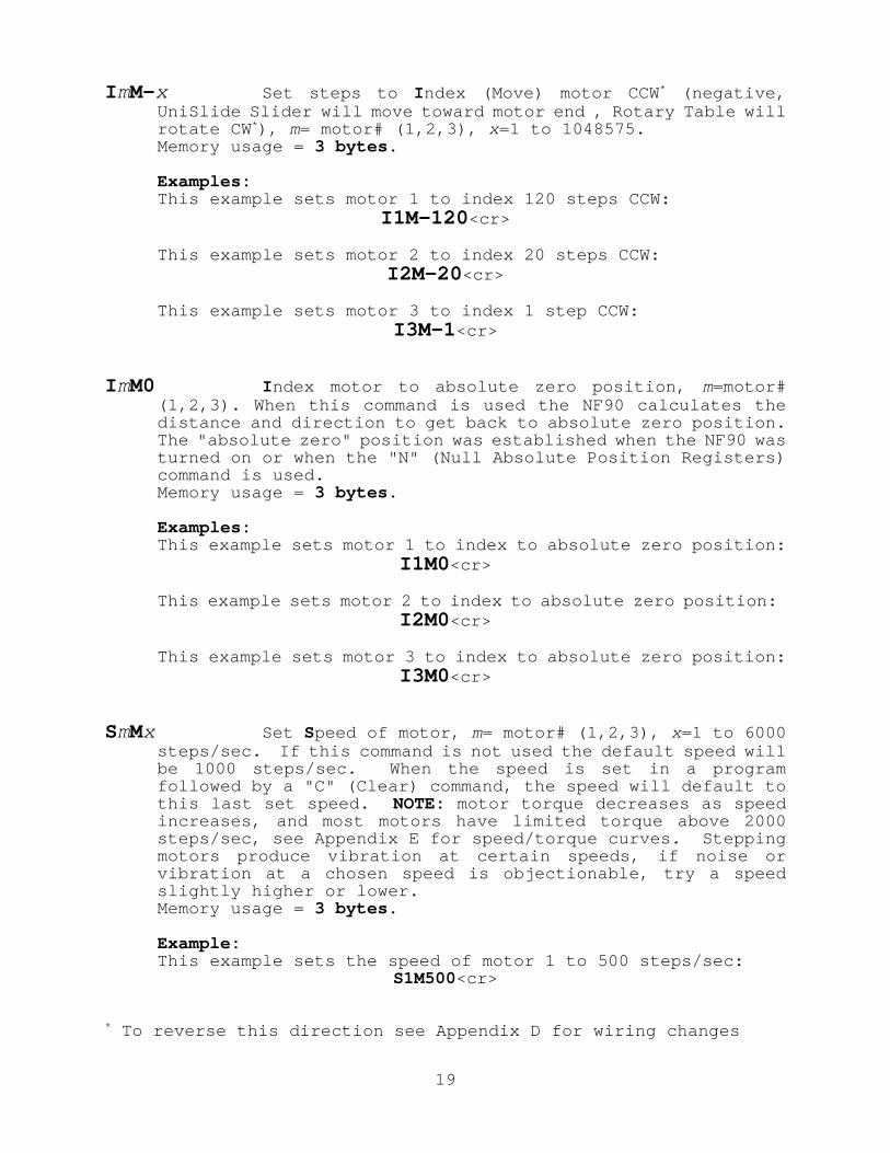
I mM-x Set steps to I ndex (Move) motor CCW * (negative,UniSlide Slider will move toward motor end , Rotary Table willrotate CW * ), m= motor# (1,2,3), x=1 to 1048575.Memory usage = 3 bytes .
Examples:This example sets motor 1 to index 120 steps CCW:
I1M-120 <cr>
This example sets motor 2 to index 20 steps CCW:I2M-20 <cr>
This example sets motor 3 to index 1 step CCW:I3M-1 <cr>
I mM0 I ndex motor to absolute zero position, m=motor#(1,2,3). When this command is used the NF90 calculates thedistance and direction to get back to absolute zero position.The "absolute zero" position was established when the NF90 wasturned on or when the "N" (Null Absolute Position Registers)command is used.Memory usage = 3 bytes .
Examples:This example sets motor 1 to index to absolute zero position:
I1M0 <cr>
This example sets motor 2 to index to absolute zero position:I2M0 <cr>
This example sets motor 3 to index to absolute zero position:I3M0 <cr>
SmMx Set Speed of motor, m= motor# (1,2,3), x=1 to 6000steps/sec. If this command is not used the default speed willbe 1000 steps/sec. When the speed is set in a programfollowed by a "C" (Clear) command, the speed will default tothis last set speed. NOTE: motor torque decreases as speedincreases, and most motors have limited torque above 2000steps/sec, see Appendix E for speed/torque curves. Steppingmotors produce vibration at certain speeds, if noise orvibration at a chosen speed is objectionable, try a speedslightly higher or lower.Memory usage = 3 bytes .
Example:This example sets the speed of motor 1 to 500 steps/sec:
S1M500<cr>
* To reverse this direction see Appendix D for wiring changes
19

AmMx Acceleration/deceleration, m= motor# (1,2,3), x=1 to50. A value of 1 is 2000 steps/sec 2, 2 is 4000 steps/sec 2, 50is 100000 steps/sec 2, etc. If this command is not used thedefault will be 1 (2000 step/sec 2). The higher the numberused, the faster the motor will reach the set speed, and thefaster it will slow down to a stop. CAUTION: motors may stallif this value is set to high.Memory usage = 0 bytes (this command is immediate, and usesa reserved memory location)
Example:
This example sets the acceleration/deceleration of motor 1 to6000 steps/sec 2:
A1M3<cr>
L0 Loop continually from the beginning. This command can beused once in a program as the last command, it functions thesame as a "continuous run input".Memory usage = 2 bytes .
L-0 Sets the Loop-to-marker at the current location in theprogram. All looping commands, except "L0", that follow thiscommand will branch to here. Loop commands prior to this onewill branch to the beginning of the program. NOTE: Thiscommand can be used only once in a program.The maximum number of loop commands a program can hold is 10before and 10 after the loop-to-marker.Memory usage = 0 bytes (this command is immediate, and uses areserved memory location)
Lx Loop from beginning or Loop-to-marker x-1 times ( x=2 to255). Loop commands can be nested for looping more than 255-1times.Memory usage = 2 bytes .
The following example loops equal (100x100x10)-1 = 99,999times:
L100,L100,L10 <cr>
NOTE: When the Loop reaches its last count, the non-loopcommand directly preceding the Loop will be ignored.
20

L- x Loop from beginning or Loop-to-marker x-1 times,alternating direction of motor 1 indexes ( x=2 to 255). Loopcommands can be nested for looping more than 255-1 times.Memory usage = 2 bytes .
The following example loops equal (100x5)-1 = 499 times:
L-100,L5 <cr>
NOTE: When the Loop reaches its last count, the non-loopcommand directly preceding the Loop will be ignored.
LM-2 Loop once from beginning or Loop-to-marker reversingindex direction of motor 2. See Example Program section foruse of this command.Memory usage = 2 bytes .
LM-3 Loop once from beginning or Loop-to-marker reversingindex direction of motor 1 and motor 2. See Example Programsection for use of this command.Memory usage = 2 bytes .
Px Pause x tenths of a second and output if output enabled( x=0 to 8191, 10 µsec pause when x=0). The USER OUT (J1,2)will go to +5V (if "pause control" is enabled) for theduration of the pause. The default is output enabled whenpausing (see U2 and U3 commands for "pause control").Memory usage = 2 bytes .
Example:
This example pauses for 15 seconds:
P150<cr>
U0 Wait for a "high" on the user input. A "high" is avoltage between +3V and +25V applied to USER IN (J1,3). Asimple pushbutton or toggle switch can be used between +5V(J1,1) and USER IN (J1,3) to satisfy this input.Memory usage = 1 byte .
U1 Wait for a "high" on the user input, holding the useroutput high while waiting. A "high" is a voltage between +3Vand +25V applied to USER IN (J1,3). The USER OUT (J1,2) willgo to +5V for the duration of the wait.Memory usage = 1 byte .
21

U2 Disable user output when pausing. Use this command whenyou do not want pauses to affect the state of USER OUT (J1,2).Memory usage = 1 byte .
U3 Enable output on USER OUT (J1,2) when pausing (resetstate)Memory usage = 1 byte .
U4 User output low. The USER OUT (J1,2) will go to +0V.This is the state of the user output on power-up. Thiscommand is used in conjunction with the "U5" command.Memory usage = 1 byte .
U5 User output high. The USER OUT (J1,2) will go to +5V.This command is used in conjunction with the "U4" command.Memory usage = 1 byte .
U6 Send "W" to the host and wait for a "G" to continue. TheNF90 sends the single character "W" to the host when thiscommand is executed. The NF90 will wait until a "G" isreceived from the host before proceeding in the program.Memory usage = 1 byte .
U7 Start of Continuous Index with pulse output. Thiscommand is used when it is desirable to make several Indexeson one axis without stopping or slowing between each Index.Instead of stopping a 20 µsec wide pulse will appear on theUSER OUT (J1,2) at each Index distance. This pulse would beused to trigger measurement/sampling equipment. The "U9"command must be used as the last command to decelerateproperly to a stop from the last Index.Memory usage = 1 byte .
Continuous Indexes require the following:
a) Each Index must be the same motor, speed, and direction.
b) After the last Index the motor will move an extradistance determined by the deceleration.
c) The first Index should be long enough (or accelerationhigh enough) for motor to reach set speed.
d) The maximum speed that should be used is 2000 steps/sec.
e) The "D" and the "H" commands can not be used.
22

Examples:
This example produces a pulse when motor 1 reaches positions1000,1100,1150,1250, and then runs back to the start position:
S1M1500,U7,I1M1000,I1M100,I1M50,I1M100,U9,I1M0 <cr>
This example will Index motor 2 and pulse 100 times:
U7,I2M400,L101,U9 <cr>
This example will run continuously producing a pulse eachrevolution of Motor 1:
U7,I1M400,L0 <cr>
U8 Start of Continuous Index sending "@" to the host. Thiscommand is the same as the "U7" except the single character"@" is transmitted at each Index distance, instead of a pulseon the USER OUT (J1,2). Always use the highest baud ratepossible (9600).Memory usage = 1 byte .
U9 End of Continuous Index. This command is used, as theending command of a Continuous Index, in conjunction with the"U7" or "U8" commands.Memory usage = 1 byte .
Bx Backlash Compensation, compensation is on when x=1, offwhen x=0 (reset state). The NF90 can compensate for mechanicalbacklash by ending every index in the positive direction.When backlash compensation is on, and a motor makes a negativeIndex, 20 steps will be added to the Index. The Motor willthen immediately reverse, indexing positive 20 steps.Memory usage = 0 bytes (this command is immediate, and uses areserved memory location)
Ox Indicate Limit Switch Over-travel to the host, off whenx=0 (reset state), NF90 sends "O" when x=1 and a limit switchis encountered. This command is useful when the host needs toknow if a positioner’s travel has been exceeded due to a motorstall or an index(es) that are too long. When Indicate LimitSwitch Over-travel is on, the NF90 transmits the singlecharacter "O" to the host when an indexing motor activatesit’s limit switch input.Memory usage = 0 bytes (this command is immediate, and uses areserved memory location)
NOTE: limit switches also stop motor motion immediately.
23
The following are immediate (not stored) commands, therefore theydo not use any of the NF90’s memory and do not need an endingcarriage return or comma:
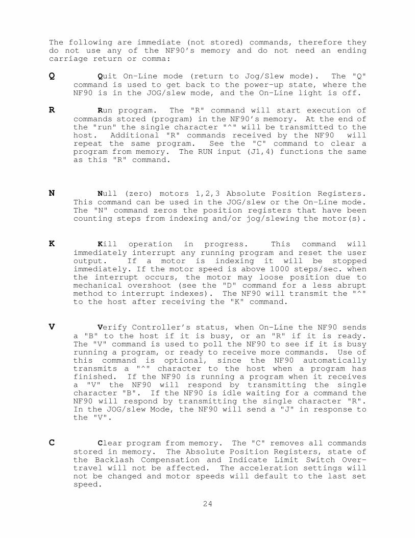
Q Quit On-Line mode (return to Jog/Slew mode). The "Q"command is used to get back to the power-up state, where theNF90 is in the JOG/slew mode, and the On-Line light is off.
R Run program. The "R" command will start execution ofcommands stored (program) in the NF90’s memory. At the end ofthe "run" the single character "^" will be transmitted to thehost. Additional "R" commands received by the NF90 willrepeat the same program. See the "C" command to clear aprogram from memory. The RUN input (J1,4) functions the sameas this "R" command.
N Null (zero) motors 1,2,3 Absolute Position Registers.This command can be used in the JOG/slew or the On-Line mode.The "N" command zeros the position registers that have beencounting steps from indexing and/or jog/slewing the motor(s).
K Kill operation in progress. This command willimmediately interrupt any running program and reset the useroutput. If a motor is indexing it will be stoppedimmediately. If the motor speed is above 1000 steps/sec. whenthe interrupt occurs, the motor may loose position due tomechanical overshoot (see the "D" command for a less abruptmethod to interrupt indexes). The NF90 will transmit the "^"to the host after receiving the "K" command.
V Verify Controller’s status, when On-Line the NF90 sendsa "B" to the host if it is busy, or an "R" if it is ready.The "V" command is used to poll the NF90 to see if it is busyrunning a program, or ready to receive more commands. Use ofthis command is optional, since the NF90 automaticallytransmits a "^" character to the host when a program hasfinished. If the NF90 is running a program when it receivesa "V" the NF90 will respond by transmitting the singlecharacter "B". If the NF90 is idle waiting for a command theNF90 will respond by transmitting the single character "R".In the JOG/slew Mode, the NF90 will send a "J" in response tothe "V".
C Clear program from memory. The "C" removes all commandsstored in memory. The Absolute Position Registers, state ofthe Backlash Compensation and Indicate Limit Switch Over-travel will not be affected. The acceleration settings willnot be changed and motor speeds will default to the last setspeed.
24

D Decelerate to a stop (interrupts current index inprogress). When the NF90 receives the single character "D"while it is indexing a motor, that motor will be deceleratedto a stop at the set deceleration. The NF90 will then proceedto the next command in the program. The "D" command has adifferent function when in the JOG/slew mode, refer to thesection on Digitizing for more information.
E Enable On-Line mode with echo on. The single character"E" is used to put the NF90 in the On-Line mode after power-up. All characters the NF90 receives will be echoed back tothe host. Refer to the section On-Line Mode for moreinformation.
F Enable On-Line mode with echo o FF. The single character"F" is used to put the NF90 in the On-Line mode after power-up. No characters will be echoed back to the host. The NF90will still respond to motor position and status requests.Refer to the section On-Line Mode for more information.
G Go after waiting or holding. The single character "G" isused to continue when the NF90 is in a single step mode ("H"command) or when a "U6" command is being executed.
H Put Controller on Hold (single step mode). When the NF90receives the single character "H" the Hold Flag will be set.With the Hold Flag set, a "running" program stops after eachoperation (command) and sends a ":" to the host. Anadditional stop occurs at the beginning and end of the programand when a loop reaches its last count. When stopped, the"X", "Y", and "Z" commands can be used to read motor position.A "G" will cause the program to continue to the nextoperation. An "H" toggles the flag off and the programcontinues as normal. The "K" terminates the program andclears the Hold Flag. This Command allows single steppingthrough a program for debugging or as a program interrupt fromthe host.
<Delete >(ASCII 127) Deletes current partial value "keyed-in". Any ASCII character greater than the value 57 willfunction as a <Delete>. The NF90 will send a "^" characterwhen it receives a <Delete>.
25

X Send position of motor 1 to the host. When the NF90receives the single character "X" it will transmit the valuefrom it’s motor 1 Absolute Position Register. Below is whatthe host would receive if motor 1 is at negative 1200. Thiscommand can be used when the motor is indexing, however speedshould be limited to 500 steps/sec. and the baud rate shouldbe 9600. See the "N" command for information on zeroing theAbsolute Position Registers.
-0001200 <cr>
Y Send position of motor 2 to the host. When the NF90receives the single character "Y" it will transmit the valuefrom it’s motor 2 Absolute Position Register. Below is whatthe host would receive if motor 2 is at positive 9201. Thiscommand can be used when the motor is indexing, however speedshould be limited to 500 steps/sec. and the baud rate shouldbe 9600. See the "N" command for information on zeroing theAbsolute Position Registers.
+0009201 <cr>
Z Send position of motor 3 to the host. When the NF90receives the single character "Z" it will transmit the valuefrom it’s motor 3 Absolute Position Register. Below is whatthe host would receive if motor 3 is at negative 20. Thiscommand can be used when the motor is indexing, however speedshould be limited to 500 steps/sec. and the baud rate shouldbe 9600. See the "N" command for information on zeroing theAbsolute Position Registers.
-0000020 <cr>
NOTE: When using the above commands, with PCs that operate below7MHz clock speed, a buffer overflow may occur in the PC’s inputbuffer. Use a lower baud rate if this error condition occurs.
The following commands are for NF90 controllers that are daisy-chained together.
[ x ] Send commands to the next NF90 in the "chain", x are anyof the previous commands. Refer to the section Daisy-chaining NF90 Controllers (P.16) for more information.
& Enable multiple NF90s that are daisy-chained. The "&"command is used in place of the "E" or "F" command when NF90controllers are daisy-chained together. Refer to the sectionDaisy-chaining NF90 Controllers (P.16) for more information.
26

Troubleshooting Procedure
SYMPTOM POSSIBLE CAUSE CORRECTIVE ACTION
Power light doesnot "light" whenNF90 is switchedon.
Blown fuse. Check fuse located on theback of the Controller.
Line cord notfully plugged in
Check line cord at powerreceptacle on back ofController
Motor does notoperate.
Limit switch(es)circuit open orswitchesimproperly wiredor missing.
Wire connectionsor connector J2may have comeloose
In-l ine fuselocated on sideof NF90 may haveblown.
Check limit switches forproper action andconnection. Make sureconnector J1 is fullyseated
Make sure connector J2 isf u l l y s e a t e d a n dconnector’s screws aretight.
Check fuse. If fuse isblown, check motor andmotor cables.
On-Line lightf l ashescontinuouslyafter power-up
Controller doesnot come On-Linewhen sent "E" or"F".
RUN input (J1,4)is activated byuser switch orjumper.
RS-232C may notbe connectedproperly.
Open connection to RUNinput (J1,4).
Trace Transmitted Data,Received Data, and SignalGround wires from yourcomputer to the NF90.
Your computer orterminal is notsending uppercase letters.
Transmit only upper caseletters. The Controllerwill not respond to lowercase.
Your computermay require ahigh on its DataSet Ready (DSR)line.
Check with the computermanufacturer to see ifthe DSR line must bepulled high, or if it canbe disabled in software.
NF90 does notcome On-Line orprogram does notoperate.
The RS-232-Cparameters arenot setproperly.
Match the RS-232-Csettings on the NF90 tothose of your computer orterminal.
27

Your computerdoes not receivedata from theController.
Your computermay require a"high" on itsRequest To Send(RTS) line.
Check with the computermanufacturer to see ifthe RTS line must bepulled high, or if it canbe disabled in software.
Motor stalls, itdoes not move atall.
Inertia insystem is tooh i g h , o rmechanism hasseized.
Hand rotate the system tolocate any binding. Alarger motor, or adifferent ratio (pitch)may be required.
Motor stalls,after rotatingslightly.
Acceleration toohigh.
Use a lower acceleration/deceleration.
Motor cannotovercomef r i c t i o n o rload.
Check mechanism for easeof movement. Load willhave to be reduced orcounterbalanced.
Motor stal lsbefore reachingmaximum speed.
Motor torque de-creases as it’sspeed increases.
Reduce steps/sec. settingof motor.
With Motorremoved fromequipment, Motorruns erraticallyat all speeds,has no torque.
Broken motorcable.
Faulty Motor.(Rare)
Check cable andconnector for brokenwires and repair breaks.
Replace Motor.
Motor or systemresonates(vibratesloudly).
The motor speedis the motor orsystem’s naturalresonant fre-quency (commonat low speeds).
Increase or decreasespeed to avoid resonancepoints. A damper orflywheel added to themotor shaft or lead screwmay dampen the resonance.
Controller stopsoperating for noapparent reason.
Inductive surgeon AC power-line.
Inductive/Staticsurges coming int h e I / Oconnections.
Isolate or remove anyequipment that may beputting "spikes" on thepower-line.
Make sure all externalequipment connected isproperly grounded andinductive loads areisolated from the NF90.
28

Specifications
FUNCTIONAL
Packaged Controller/Driver, using Microcomputer control of steppingmotors. Operates one to three (dependent on model) motors,one-at-a-time.
Interactive limit switch inputs (TTL), (CW and CCW for each axis).
One User Input (0V to +3V min., -25V to +25V max.), and one UserOutput (0 or +5V, 10 ma sinking and 3 ma sourcing capability).
Programming through full-duplex RS-232-C; 300,1200,4800,9600 Baud(switch settable), 7 Data bits, Even parity, 2 Stop bits, ASCII;special configurations with 8 data bits, odd or no parity, areavailable.
User available RAM for program storage is 101 bytes
Remote Run and joystick Inputs (TTL).
Eight foot ( 244 cm ) motor and limit switch cables with connectors
MOTOR COMPATIBILITY
1.8 o PM 6 or 8 lead stepping motors, 4.7 amp/phase maximum.Factory matched for a particular motor current, motors on each axisto be the same amp/phase value.
PHYSICAL
Weight: 7.2 lbs. ( 3.2 kg )Height: 5.0 inches ( 12.7 cm )Width: 10.8 inches ( 27.4 cm )Depth: 7.8 inches ( 19.8 cm )
ELECTRICAL REQUIREMENTS
90 to 130 VAC 50/60Hz, 150 watts
ENVIRONMENTAL
35o to 95 o F ( 2 o to 35 o C ) Convection cooled
MODELS
Model # NF90-1 One motor versionModel # NF90-2 Two motor versionModel # NF90-3 Three motor version
29

Appendix ASwitch settings and RS-232-C Connections (7 Data,Even,2 Stop)
Suggested RS-232 Cable Configuration
IBM PC,XT,AT, & NF90Compatibles Controller
Serial (25 Pin) J1
TX 2 18 RXRX 3 17 TXGND 7 16 GNDRTS 4CTS 5DSR 6DTR 20
Serial (9 Pin) J1
RX 2 17 TXTX 3 18 RXGND 5 16 GNDDTR 4DSR 6RTS 7CTS 8
30

Appendix B
Limit Switch and Joystick Connections
31

Appendix CUSER OUT, USER IN, and RUN Connections
32

Appendix D
Motor Connections
33
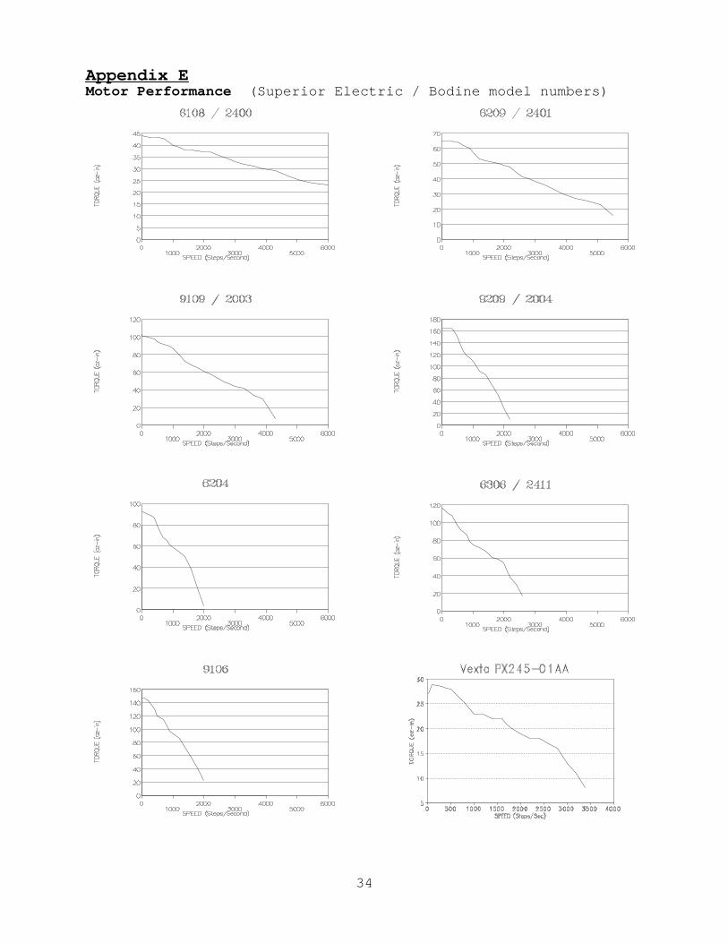
Appendix EMotor Performance (Superior Electric / Bodine model numbers)
34

Limited Two Year WarrantyVelmex warrants this Controller against defects in material and workmanship for a period of twoyears from date of shipment. In case of defect, Velmex will repair this Controller withoutcharge. The user will be responsible for shipment to Velmex, and will be charged a minimum of$45.00 for non-warranty service.
For service under this warranty:
1. Contact Velmex to obtain a Return Authorization number (Tel. 716-657-6151).2. Pack Controller in the original container or equal.3. Enclose a description of the problem, along with the return address, the name of
the end user, his/her telephone and fax number. 4. Ship Controller Prepaid and insured to :
Velmex, Inc7550 State Route 5&20Bloomfield, NY 14469
Exclusions and Limitations:
This warranty covers step motor controllers manufactured by Velmex, Inc. Externalelectrical cables and connectors are not covered for wear and breakage. This warrantydoes not extend to any damage or malfunction resulting from misuse, neglect or accident. Except for any implied warranty, this warranty contains the entire obligation of Velmex,and the remedies described above are the exclusive remedies under this warranty or anyimplied warranty. The duration of any implied warranty is limited to two years. In NoEvent Shall Velmex Be Liable For Incidental or ConsequentialDamages.


