5.1 Three steps of the OptiTrack calibration process . . . . . . . . . . . . 355.2 Default skeleton for the OptiTrack system . . . . . . . . . . . . . . . . 36
6.1 Skeleton weights applied on clothes. . . . . . . . . . . . . . . . . . . . 406.2 Test: the process took more than usual, and the embedding is incorrect. 416.3 The skeleton is completely rotated, plus the feet joints are incorrect. . 416.4 The joints of the arms are incorrect. . . . . . . . . . . . . . . . . . . . 42
I would like to thank Dr. Bernhard Spanlang for his patience during the longdevelopment stage and the inestimable support and guidance given throughoutthe whole project. Also many thanks to Prof. Mel Slater, Dr. Marta Fairen, andDr. Frederic Perez for reviewing this thesis; and to Claudia, my family, friendsand colleagues for all the support and love given while I was busy.
Barcelona June 25th 2008
Marc Boquet Bertran
v
Abstract
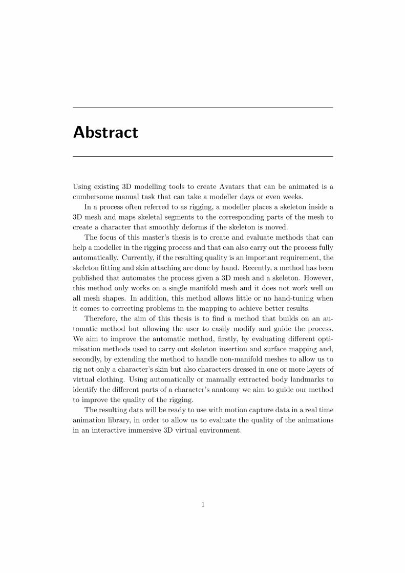
Using existing 3D modelling tools to create Avatars that can be animated is acumbersome manual task that can take a modeller days or even weeks.
In a process often referred to as rigging, a modeller places a skeleton inside a3D mesh and maps skeletal segments to the corresponding parts of the mesh tocreate a character that smoothly deforms if the skeleton is moved.
The focus of this master’s thesis is to create and evaluate methods that canhelp a modeller in the rigging process and that can also carry out the process fullyautomatically. Currently, if the resulting quality is an important requirement, theskeleton fitting and skin attaching are done by hand. Recently, a method has beenpublished that automates the process given a 3D mesh and a skeleton. However,this method only works on a single manifold mesh and it does not work well onall mesh shapes. In addition, this method allows little or no hand-tuning whenit comes to correcting problems in the mapping to achieve better results.
Therefore, the aim of this thesis is to find a method that builds on an au-tomatic method but allowing the user to easily modify and guide the process.We aim to improve the automatic method, firstly, by evaluating different opti-misation methods used to carry out skeleton insertion and surface mapping and,secondly, by extending the method to handle non-manifold meshes to allow us torig not only a character’s skin but also characters dressed in one or more layers ofvirtual clothing. Using automatically or manually extracted body landmarks toidentify the different parts of a character’s anatomy we aim to guide our methodto improve the quality of the rigging.
The resulting data will be ready to use with motion capture data in a real timeanimation library, in order to allow us to evaluate the quality of the animationsin an interactive immersive 3D virtual environment.
1
Chapter 1
Introduction
The objective of this Master’s Thesis is to provide modellers with a comprehen-sive method of rigging, clothing and animation of virtual characters. Riggingis the process of creating the necessary information for a static character to beanimated. It will be described in detail through the following chapters.
This chapter starts with a short introduction to the basics of 3D characteranimation, its use in various fields and the different requirements that each ofthese fields present with respect to the resulting animated virtual human, oftenreferred to as an ’avatar’. In addition, a description of the process of creatingavatars is given. Afterwards, the objective of this thesis is presented, as well as abrief summary of the contributions made. The chapter finishes with an overviewof the rest of the chapters.
1.1 Introduction to 3D character animation
This section reviews some of the many areas that take advantage of 3D avatars,focusing on the different requirements of every field. In addition, the creationprocess of a 3D character will be described.
Application areas
One of the main fields where the presence of animated 3D characters is morenoticeable is the film industry. The growing number of movies produced usingcomputer graphics contributes to innovations in the field. Some film makingcompanies such as Pixar have research groups working on new techniques ofmodelling, animation or illumination among others, and the improvements madeby this industry often benefit other fields. The requirements for movies are usually
2
CHAPTER 1. INTRODUCTION 3
quite high, the characters must be nearly perfect, both for their appearance andtheir movements.
The presence of avatars has also been growing in the other major industry ofentertainment, video games. For many years now, there are an increasing numberof games that make use of 3D graphics, which require in most cases the creationof new animated characters from scratch. As in the case of movies, the charactersin video games often need to look very real while permitting interactive framerates, and their movements have to be sufficiently accurate.
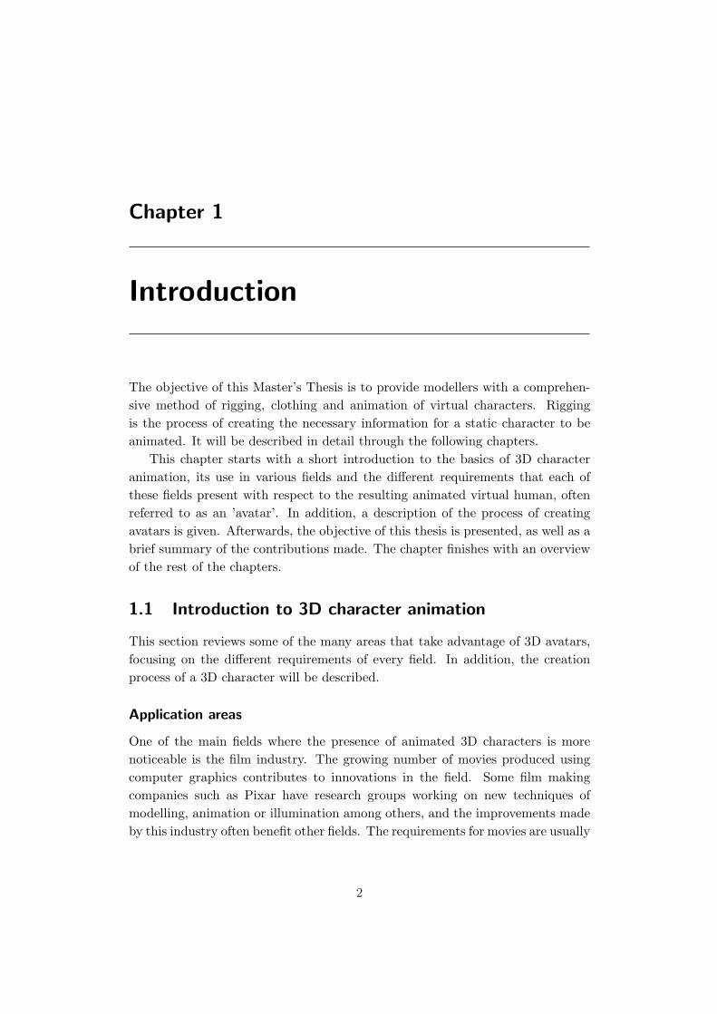
Online worlds, such as Second Life [49], represent another approach to thesubject. While still being considered as a type of video games, its requirementswith respect to the avatars differ. These applications must allow quite a highnumber of people to connect together from any part of the world, and the move-ment of the avatars must be close to real time. The fact that the data mustbe able to travel through the internet may require the 3D models to have a lowresolution, otherwise the amount of data transferred could be prohibitive for theapplication to run smoothly. Figure 1.1 shows Second Life characters; the lowpolygon level is noticeable, most of the detail is offered by the textures.
Figure 1.1: Some Second Life avatars.
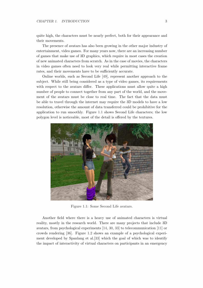
Another field where there is a heavy use of animated characters is virtualreality, mostly in the research world. There are many projects that include 3Davatars, from psychological experiments [14, 30, 33] to telecommunication [11] orcrowds rendering [36]. Figure 1.2 shows an example of a psychological experi-ment developed by Spanlang et al.[33] which the goal of which was to identifythe impact of interactivity of virtual characters on participants in an emergency
CHAPTER 1. INTRODUCTION 4
situation. Furthermore, some recent researches [31] have demonstrated that invirtual reality visual realism does not influences as much as it may seem withrespect to the user perception.
Figure 1.2: Emergency situations in virtual reality.
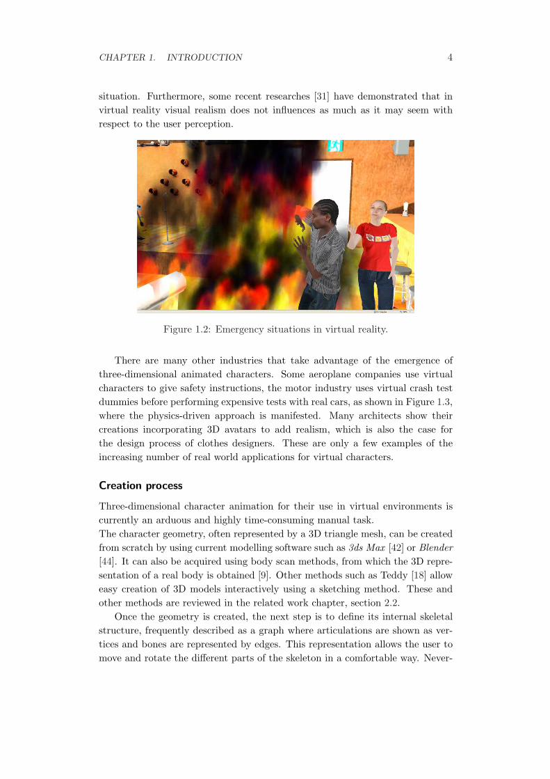
There are many other industries that take advantage of the emergence ofthree-dimensional animated characters. Some aeroplane companies use virtualcharacters to give safety instructions, the motor industry uses virtual crash testdummies before performing expensive tests with real cars, as shown in Figure 1.3,where the physics-driven approach is manifested. Many architects show theircreations incorporating 3D avatars to add realism, which is also the case forthe design process of clothes designers. These are only a few examples of theincreasing number of real world applications for virtual characters.
Creation process
Three-dimensional character animation for their use in virtual environments iscurrently an arduous and highly time-consuming manual task.The character geometry, often represented by a 3D triangle mesh, can be createdfrom scratch by using current modelling software such as 3ds Max [42] or Blender[44]. It can also be acquired using body scan methods, from which the 3D repre-sentation of a real body is obtained [9]. Other methods such as Teddy [18] alloweasy creation of 3D models interactively using a sketching method. These andother methods are reviewed in the related work chapter, section 2.2.
Once the geometry is created, the next step is to define its internal skeletalstructure, frequently described as a graph where articulations are shown as ver-tices and bones are represented by edges. This representation allows the user tomove and rotate the different parts of the skeleton in a comfortable way. Never-
CHAPTER 1. INTRODUCTION 5
Figure 1.3: Virtual Crash Dummy.
theless, the skeleton is not attached to the actual character, so there is a need tospecify which parts of the surface are attached to which bone, a process calledrigging or skinning. Manual rigging is a tedious task, which requires assigningweights to all the bones with respect to every polygon of the mesh. Fortunatelythere are some automatic methods to establish the rigging, such as Pinocchio [2].
Once the rigging is done, the character moves along with the skeleton, butit may need clothes, and these will have to move too. For this step, the toolcreated by Spanlang et al. [34] was used, which is capable of computing adjustedclothes to a given model. The next step is to attach the clothes to the skin inorder to be able to animate them too, using the previously computed weightinformation from the bones and the skin. After these steps, the user should beable to animate the model, using motion-capture or other animation methods, asexplained in chapter 5.
Different needs, different solutions
As we have seen, there are many areas where virtual characters may be needed.Depending on the field of work, however, the final quality of this avatar may bemore or less important compared within the context of the whole project. Forexample, in most of the current video games, their final success depends in agreat measure on the quality of their graphics and animations. This fact justifiesthe high number of hours spent on the creation of the characters. In some otherfields, however, the job of modelling and animating virtual characters is not that
CHAPTER 1. INTRODUCTION 6
significant for the success of the project. For instance, researchers in virtual re-ality or other areas may need easy-to-create characters in order to perform theactual study. These characters have to be animated, but a quality loss on thefinal animation may be justified by the saved amount of time.The current automatic techniques do not offer a global approach that minimisesthe manual effort needed to accomplish the whole process, thus compelling mod-ellers to require several days working on the animation of a single avatar.
1.2 Objective
This master’s thesis presents a fast and easy-to-use method for animating 3Dcharacters automatically while allowing the user to tweak the results if necessary.This method should be able to automatically provide a correct result in mostof the cases, as well as it should offer an easy way of manual tuning of theprocess when necessary. The result should be saved in a well known file format,directly usable in most professional modelling and animation systems. There aresome existing methods of automatic rigging, but user interaction is difficult, andtheir integration with current modelling software is nonexistent. This processis applicable to polygonal biped models, either human or fantasy characters. Itcould also be applied to other models such as quadruped, but unfortunately thelack of free 3d models for these kind of characters has prevented us to test it.
1.3 Contributions
The following contributions have been made in this thesis:
• An integration of the Pinocchio automatic rigging method with the FBXfile format [50], allowing to incorporate the results in some of the mostlyused modelling and animation software.
• Attaching clothes to the rigged character. An existing technique of clothcreation has been used to obtain static clothes, and the deformation hasbeen applied to them so the clothes move along with the character. In orderto achieve more realistic results, textures have been added to the clothes.
• A separation of the different steps of the rigging process in order to let theuser review or modify the automatic result after each step. It is also allowedto run each step of the process individually.
• The resulting character has been animated using motion-capture. We pro-vide and discuss an analysis of the different results based on various pa-rameters used during the rigging process.
CHAPTER 1. INTRODUCTION 7
1.4 Overview of the rest of the thesis
The structure of the rest of this thesis is outlined in the following.
Chapter 2: Related work
In this chapter existing methods of rigging and animation of 3D characters arereviewed. The different parts of the process –skeletal placement, rigging, clothingand animation– are examined separately, and the advantages and disadvantagesof the different approaches are analysed. Finally, one of these methods is chosenas a basis for the thesis.
Chapter 3: Rigging
In this chapter the automatic rigging process is explained and reviewed in de-tail. First, the fundamentals of the mathematical theory behind the Pinocchiolibrary [2] are given, then some implementation details are shown. Furthermore,we describe the integration of this existing library with our software, using theSoftware Development Kit (SDK) of the FBX file format [50].
Chapter 4: Clothing
In this chapter the method used for the creation of the clothes is described. Theclothing system from Spanlang and others [34] is used to obtain static clothesvirtually tried on geometry obtained by a whole body scanner. The clothes mustbe attached to the skin in order to allow their deformation along with the skeletalmodel. The procedure to find the correct attachment for the clothes meshes isexplained.
Chapter 5: Animation
In order to review the results of the process, realistic animations are needed.Several animations have been captured and applied to the resulting models. Thischapter gives details of the motion-capture technique that has been used to obtainthe animations that will be applied to the character, the Optitrack software Arena[32].
Chapter 6: Results
Some results are shown and analysed, searching for inconsistencies in the var-ious animations and different configuration options used. We present a set oftechniques to identify these inconsistencies in order to avoid them.
CHAPTER 1. INTRODUCTION 8
Chapter 7: Conclusions and Future Work
This chapter presents the conclusions of the thesis. Also possible lines of furtherresearch are suggested.
1.5 Summary
In this chapter an overview of the different fields using 3D characters has beengiven, as well as a short description of their creation process and a review of someof the creation techniques. Also, the objective of this thesis has been presented,along with the contributions made. The chapter has ended with an overview ofthe rest of the chapters.
The next chapter will present the existing research work in the field, brieflyreviewing the most important techniques with respect to this thesis.
Chapter 2
Related work
This chapter describes some of the existing methods of character modelling andanimation in 3D, stating their advantages and disadvantages. Solving some ofthese disadvantages is an objective of this thesis, and this chapter briefly describeshow they are addressed.
2.1 Overview
Professional modellers and animators use 3D software such as Maya [43], 3ds Max[42] or LightWave [47] for the creation of new characters, and they tend to do agreat part of the process manually. This situation is not likely to change in thenext few years, as this software gives modellers the freedom they need to manuallycreate high-detail models for their use in movies or video games, and most of these3D artists prefer to sculpt their creations contributing with their human touch,rather than having a machine doing all the work [10]. However, this approachis not affordable by amateur animators or researchers that may need an easy-to-create animated character; therefore some other approaches have appeared toprovide a faster way of creating and animating an avatar, even though the finalresult may not be as refined as if performed by a skilled modeller.
2.2 Modelling
The first step in the creation of an animated character is modelling. Starting fromscratch the objective is to obtain a three-dimensional triangle mesh representinga real-life model, in this case a person. A brief review of some of the severalexisting methods is given in this section.
9
CHAPTER 2. RELATED WORK 10
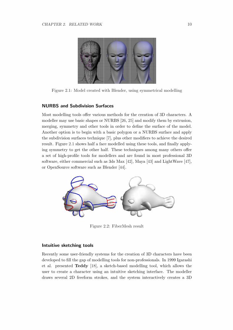
Figure 2.1: Model created with Blender, using symmetrical modelling
NURBS and Subdivision Surfaces
Most modelling tools offer various methods for the creation of 3D characters. Amodeller may use basic shapes or NURBS [26, 25] and modify them by extrusion,merging, symmetry and other tools in order to define the surface of the model.Another option is to begin with a basic polygon or a NURBS surface and applythe subdivision surfaces technique [7], plus other modifiers to achieve the desiredresult. Figure 2.1 shows half a face modelled using these tools, and finally apply-ing symmetry to get the other half. These techniques among many others offera set of high-profile tools for modellers and are found in most professional 3Dsoftware, either commercial such as 3ds Max [42], Maya [43] and LightWave [47],or OpenSource software such as Blender [44].
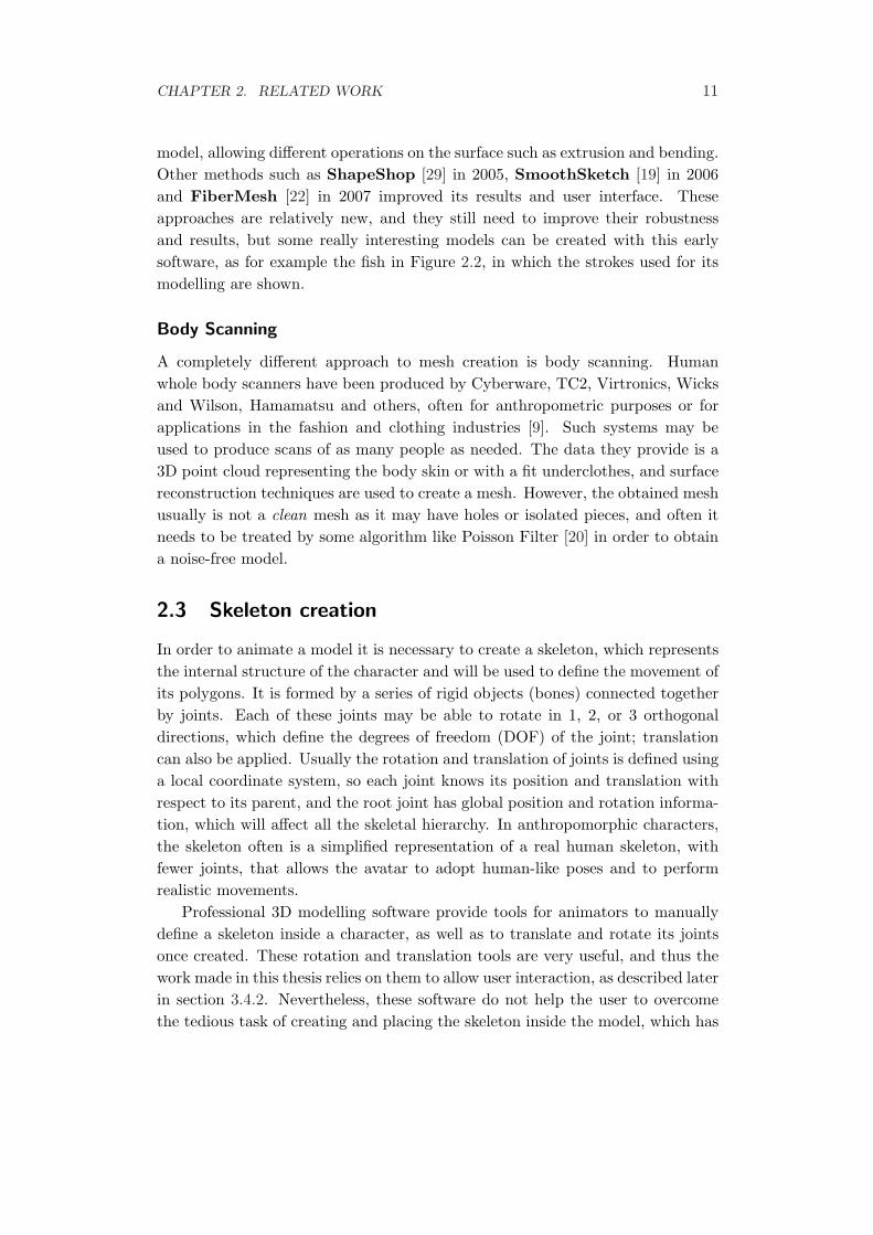
Figure 2.2: FiberMesh result
Intuitive sketching tools
Recently some user-friendly systems for the creation of 3D characters have beendeveloped to fill the gap of modelling tools for non-professionals. In 1999 Igarashiet al. presented Teddy [18], a sketch-based modelling tool, which allows theuser to create a character using an intuitive sketching interface. The modellerdraws several 2D freeform strokes, and the system interactively creates a 3D
CHAPTER 2. RELATED WORK 11
model, allowing different operations on the surface such as extrusion and bending.Other methods such as ShapeShop [29] in 2005, SmoothSketch [19] in 2006and FiberMesh [22] in 2007 improved its results and user interface. Theseapproaches are relatively new, and they still need to improve their robustnessand results, but some really interesting models can be created with this earlysoftware, as for example the fish in Figure 2.2, in which the strokes used for itsmodelling are shown.
Body Scanning
A completely different approach to mesh creation is body scanning. Humanwhole body scanners have been produced by Cyberware, TC2, Virtronics, Wicksand Wilson, Hamamatsu and others, often for anthropometric purposes or forapplications in the fashion and clothing industries [9]. Such systems may beused to produce scans of as many people as needed. The data they provide is a3D point cloud representing the body skin or with a fit underclothes, and surfacereconstruction techniques are used to create a mesh. However, the obtained meshusually is not a clean mesh as it may have holes or isolated pieces, and often itneeds to be treated by some algorithm like Poisson Filter [20] in order to obtaina noise-free model.
2.3 Skeleton creation
In order to animate a model it is necessary to create a skeleton, which representsthe internal structure of the character and will be used to define the movement ofits polygons. It is formed by a series of rigid objects (bones) connected togetherby joints. Each of these joints may be able to rotate in 1, 2, or 3 orthogonaldirections, which define the degrees of freedom (DOF) of the joint; translationcan also be applied. Usually the rotation and translation of joints is defined usinga local coordinate system, so each joint knows its position and translation withrespect to its parent, and the root joint has global position and rotation informa-tion, which will affect all the skeletal hierarchy. In anthropomorphic characters,the skeleton often is a simplified representation of a real human skeleton, withfewer joints, that allows the avatar to adopt human-like poses and to performrealistic movements.
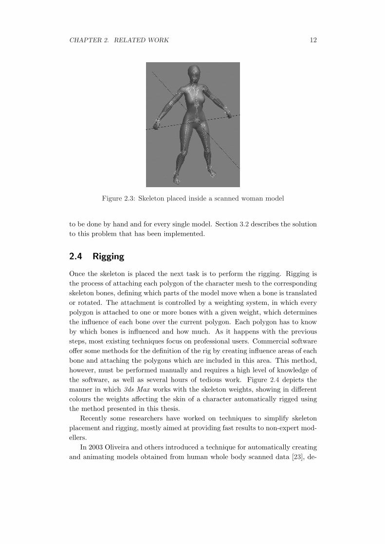
Professional 3D modelling software provide tools for animators to manuallydefine a skeleton inside a character, as well as to translate and rotate its jointsonce created. These rotation and translation tools are very useful, and thus thework made in this thesis relies on them to allow user interaction, as described laterin section 3.4.2. Nevertheless, these software do not help the user to overcomethe tedious task of creating and placing the skeleton inside the model, which has
CHAPTER 2. RELATED WORK 12
Figure 2.3: Skeleton placed inside a scanned woman model
to be done by hand and for every single model. Section 3.2 describes the solutionto this problem that has been implemented.
2.4 Rigging
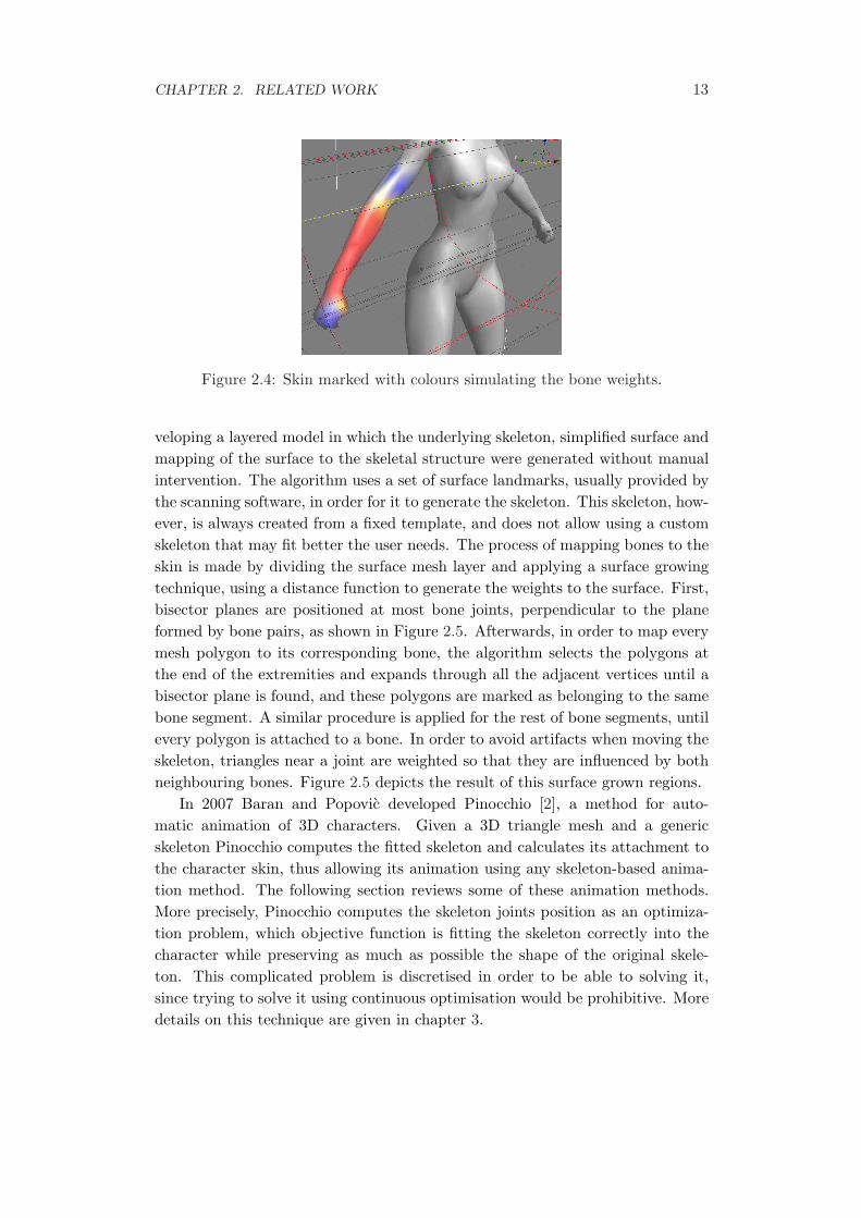
Once the skeleton is placed the next task is to perform the rigging. Rigging isthe process of attaching each polygon of the character mesh to the correspondingskeleton bones, defining which parts of the model move when a bone is translatedor rotated. The attachment is controlled by a weighting system, in which everypolygon is attached to one or more bones with a given weight, which determinesthe influence of each bone over the current polygon. Each polygon has to knowby which bones is influenced and how much. As it happens with the previoussteps, most existing techniques focus on professional users. Commercial softwareoffer some methods for the definition of the rig by creating influence areas of eachbone and attaching the polygons which are included in this area. This method,however, must be performed manually and requires a high level of knowledge ofthe software, as well as several hours of tedious work. Figure 2.4 depicts themanner in which 3ds Max works with the skeleton weights, showing in differentcolours the weights affecting the skin of a character automatically rigged usingthe method presented in this thesis.
Recently some researchers have worked on techniques to simplify skeletonplacement and rigging, mostly aimed at providing fast results to non-expert mod-ellers.
In 2003 Oliveira and others introduced a technique for automatically creatingand animating models obtained from human whole body scanned data [23], de-
CHAPTER 2. RELATED WORK 13
Figure 2.4: Skin marked with colours simulating the bone weights.
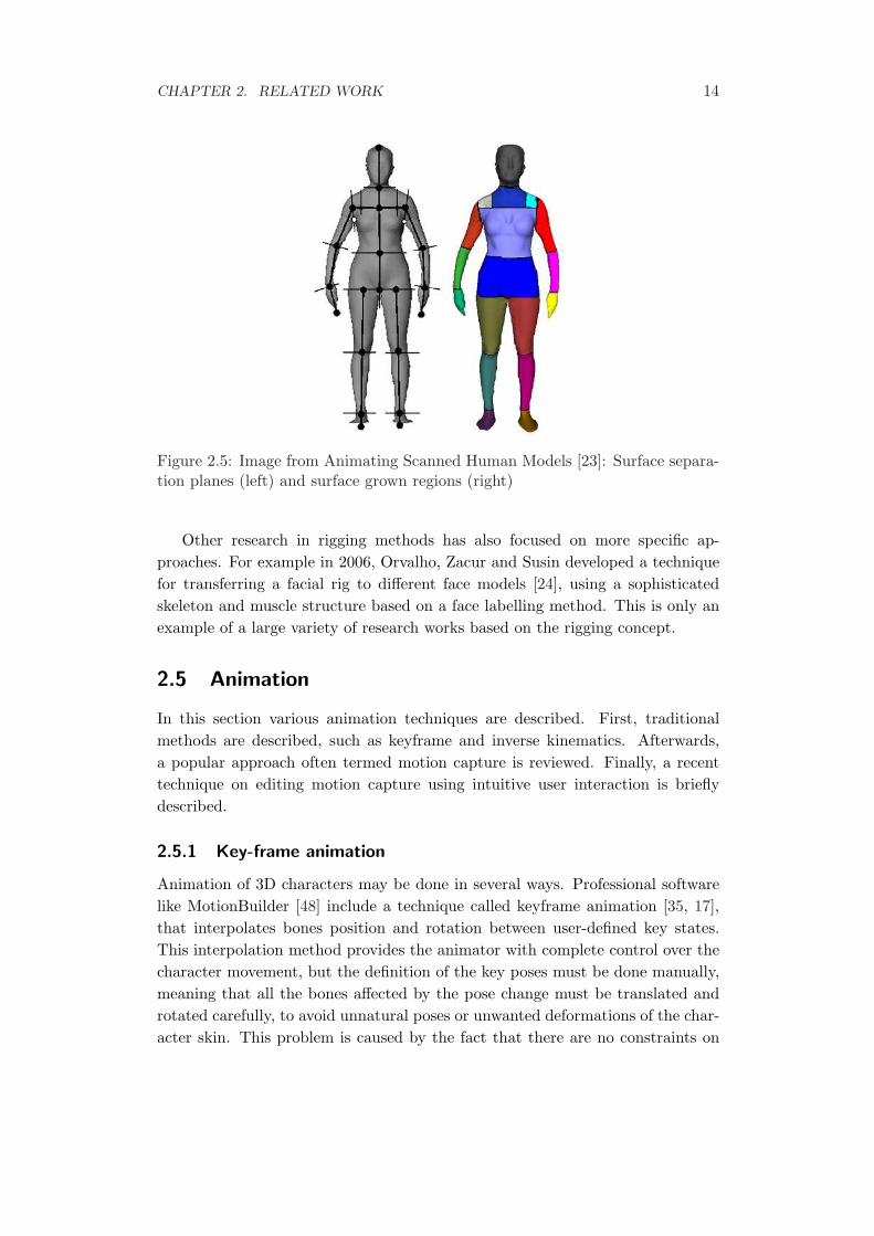
veloping a layered model in which the underlying skeleton, simplified surface andmapping of the surface to the skeletal structure were generated without manualintervention. The algorithm uses a set of surface landmarks, usually provided bythe scanning software, in order for it to generate the skeleton. This skeleton, how-ever, is always created from a fixed template, and does not allow using a customskeleton that may fit better the user needs. The process of mapping bones to theskin is made by dividing the surface mesh layer and applying a surface growingtechnique, using a distance function to generate the weights to the surface. First,bisector planes are positioned at most bone joints, perpendicular to the planeformed by bone pairs, as shown in Figure 2.5. Afterwards, in order to map everymesh polygon to its corresponding bone, the algorithm selects the polygons atthe end of the extremities and expands through all the adjacent vertices until abisector plane is found, and these polygons are marked as belonging to the samebone segment. A similar procedure is applied for the rest of bone segments, untilevery polygon is attached to a bone. In order to avoid artifacts when moving theskeleton, triangles near a joint are weighted so that they are influenced by bothneighbouring bones. Figure 2.5 depicts the result of this surface grown regions.
In 2007 Baran and Popovic developed Pinocchio [2], a method for auto-matic animation of 3D characters. Given a 3D triangle mesh and a genericskeleton Pinocchio computes the fitted skeleton and calculates its attachment tothe character skin, thus allowing its animation using any skeleton-based anima-tion method. The following section reviews some of these animation methods.More precisely, Pinocchio computes the skeleton joints position as an optimiza-tion problem, which objective function is fitting the skeleton correctly into thecharacter while preserving as much as possible the shape of the original skele-ton. This complicated problem is discretised in order to be able to solving it,since trying to solve it using continuous optimisation would be prohibitive. Moredetails on this technique are given in chapter 3.
CHAPTER 2. RELATED WORK 14
Figure 2.5: Image from Animating Scanned Human Models [23]: Surface separa-tion planes (left) and surface grown regions (right)
Other research in rigging methods has also focused on more specific ap-proaches. For example in 2006, Orvalho, Zacur and Susin developed a techniquefor transferring a facial rig to different face models [24], using a sophisticatedskeleton and muscle structure based on a face labelling method. This is only anexample of a large variety of research works based on the rigging concept.
2.5 Animation
In this section various animation techniques are described. First, traditionalmethods are described, such as keyframe and inverse kinematics. Afterwards,a popular approach often termed motion capture is reviewed. Finally, a recenttechnique on editing motion capture using intuitive user interaction is brieflydescribed.
2.5.1 Key-frame animation
Animation of 3D characters may be done in several ways. Professional softwarelike MotionBuilder [48] include a technique called keyframe animation [35, 17],that interpolates bones position and rotation between user-defined key states.This interpolation method provides the animator with complete control over thecharacter movement, but the definition of the key poses must be done manually,meaning that all the bones affected by the pose change must be translated androtated carefully, to avoid unnatural poses or unwanted deformations of the char-acter skin. This problem is caused by the fact that there are no constraints on
CHAPTER 2. RELATED WORK 15
the bones. For example, if an animator wants to move an arm of the character,the shoulder will have to be rotated, and the elbow and the wrist probably willhave to be adjusted too, taking care not to achieve an anatomically wrong posi-tion. The subsequent interpolation between the two key positions will create theintermediate states, generating an animation.
2.5.2 Inverse Kinematics
These deficiencies in the basic key-frame animation method led to the incorpora-tion of inverse kinematics techniques [51, 16], adopted from the existing researchand application in the field of robotics. This method adds a series of constraintsto the character skeleton to achieve realistic poses with less effort than using basicrotation and translation of joints. To summarise, inverse kinematics work witha hierarchical kinematic chain of joints, some of which may be defined as end-effectors, usually the ones at the end of a chain. These end-effectors are the jointsover which the animator has control, translating them directly to any location,and the inverse kinematics will solve the necessary rotations for the rest of thejoints. No joint rotations must be given at all, the method takes care of the hardwork of positioning the whole skeleton to match the translation constraint givenby the user. As presented by Chadwick and others in their Critter system [8],this technique combined with the keyframe interpolation contributes to relievingthe animator from some of the more tedious aspects of creating new animationsby hand.
Because of these advantages nowadays most of the professional animationsoftware includes inverse kinematics and key-framing techniques as the defaultanimation mode, since it reduces in great measure the time and effort needed tocreate a realistic animation.
2.5.3 Motion capture
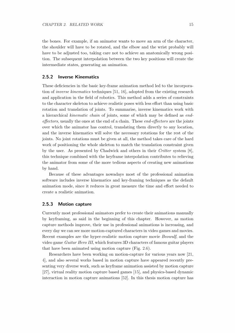
Currently most professional animators prefer to create their animations manuallyby keyframing, as said in the beginning of this chapter. However, as motioncapture methods improve, their use in professional animations is increasing, andevery day we can see more motion-captured characters in video games and movies.Recent examples are the hyper-realistic motion capture movie Beowulf, and thevideo game Guitar Hero III, which features 3D characters of famous guitar playersthat have been animated using motion capture (Fig. 2.6).
Researchers have been working on motion-capture for various years now [21,4], and also several works based in motion capture have appeared recently pre-senting very diverse work, such as keyframe animation assisted by motion capture[27], virtual reality motion capture based games [15], and physics-based dynamicinteraction in motion capture animations [52]. In this thesis motion capture has
CHAPTER 2. RELATED WORK 16
been used to obtain the animations that are used on the character. In Chapter 5the motion capture process is described in detail.
2.5.4 Alternative animation methods
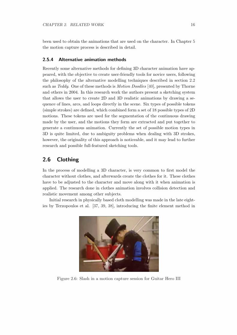
Recently some alternative methods for defining 3D character animation have ap-peared, with the objective to create user-friendly tools for novice users, followingthe philosophy of the alternative modelling techniques described in section 2.2such as Teddy. One of these methods is Motion Doodles [40], presented by Thorneand others in 2004. In this research work the authors present a sketching systemthat allows the user to create 2D and 3D realistic animations by drawing a se-quence of lines, arcs, and loops directly in the scene. Six types of possible tokens(simple strokes) are defined, which combined form a set of 18 possible types of 2Dmotions. These tokens are used for the segmentation of the continuous drawingmade by the user, and the motions they form are extracted and put together togenerate a continuous animation. Currently the set of possible motion types in3D is quite limited, due to ambiguity problems when dealing with 3D strokes,however, the originality of this approach is noticeable, and it may lead to furtherresearch and possible full-featured sketching tools.
2.6 Clothing
In the process of modelling a 3D character, is very common to first model thecharacter without clothes, and afterwards create the clothes for it. These clotheshave to be adjusted to the character and move along with it when animation isapplied. The research done in clothes animation involves collision detection andrealistic movement among other subjects.
Initial research in physically based cloth modelling was made in the late eight-ies by Terzopoulos et al. [37, 39, 38], introducing the finite element method in
Figure 2.6: Slash in a motion capture session for Guitar Hero III
CHAPTER 2. RELATED WORK 17
Figure 2.7: Motion Doodles example sequence
this field. Ten years later, Baraff and Witkin solved some of the initial problemsof this technique [1].
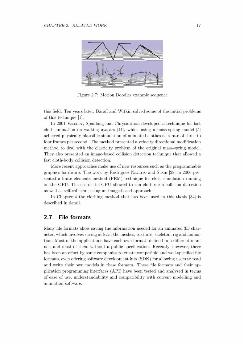
In 2001 Vassilev, Spanlang and Chrysanthou developed a technique for fastcloth animation on walking avatars [41], which using a mass-spring model [5]achieved physically plausible simulation of animated clothes at a rate of three tofour frames per second. The method presented a velocity directional modificationmethod to deal with the elasticity problem of the original mass-spring model.They also presented an image-based collision detection technique that allowed afast cloth-body collision detection.
More recent approaches make use of new resources such as the programmablegraphics hardware. The work by Rodriguez-Navarro and Susin [28] in 2006 pre-sented a finite elements method (FEM) technique for cloth simulation runningon the GPU. The use of the GPU allowed to run cloth-mesh collision detectionas well as self-collision, using an image-based approach.
In Chapter 4 the clothing method that has been used in this thesis [34] isdescribed in detail.
2.7 File formats
Many file formats allow saving the information needed for an animated 3D char-acter, which involves saving at least the meshes, textures, skeleton, rig and anima-tion. Most of the applications have each own format, defined in a different man-ner, and most of them without a public specification. Recently, however, therehas been an effort by some companies to create compatible and well-specified fileformats, even offering software development kits (SDK) for allowing users to readand write their own models in these formats. These file formats and their ap-plication programming interfaces (API) have been tested and analysed in termsof ease of use, understandability and compatibility with current modelling andanimation software.
CHAPTER 2. RELATED WORK 18
2.7.1 Cal3D
Cal3D [45] is an opensource skeletal-based animation library providing its ownfile format, originally developed for its use in video games and currently be-ing maintained by the opensource community. Despite initial efforts like im-porters/exporters for the major modelling software, its development is in stand-by since 2006 and the community is not very active. Furthermore, its integrationwith current software is very poor.
2.7.2 Collada
Collada [46] is an interchange file format, defined in XML and implementing allthe features needed in a 3D application. It is widely supported, so most of thecurrent tools have importers and exporters of Collada files. Its main use is in videogames, but also is widely used in other fields. It has a very active communityand a solid user base, formed by modellers and animators as well as developersthat use its open source SDK. Collada also contains some other packages otherthan the file format, such as physics support or definition of shader effects for thevisualisation.
2.7.3 FBX
The FBX [50] file format was originally developed by Kaydara, a 3D companythat was bought by Autodesk. Since the acquisition, the FBX became widelysupported by professional software, and has a free to use proprietary SDK. Asfor its features, it is very similar to Collada. And like Collada it has a largenumber of users, but its major weakness is the fact that it is not opensource andso its lack of an active community supporting it.
The file format that would have been more interesting to use in this thesisis Collada, for its large user base and its promising future. However, since thesoftware used for character modelling and animation was from Autodesk (3dsMax and MotionBuilder), the Collada files had to be loaded and saved usinga plug-in. This plug-in for export and import was tested and presented sometrouble, thus finally the decision was to use FBX, which is native on Autodeskproducts and have a highly documented SDK as well, although not such a biguser community. A more detailed description of the incorporation of this fileformat in the thesis can be found in section 3.4.1.
2.8 Summary
This chapter has shown a review of related work on the whole process of mod-elling, rigging, and animation of a 3D character, explaining briefly some of the
CHAPTER 2. RELATED WORK 19
related work. Other related work such as cloth animation has also been brieflyreviewed, as well as the different file formats for 3D content storage.
In the next chapter a detailed description of the rigging process is given, aswell as implementation details for the integration made with the FBX file format.
Chapter 3
Rigging
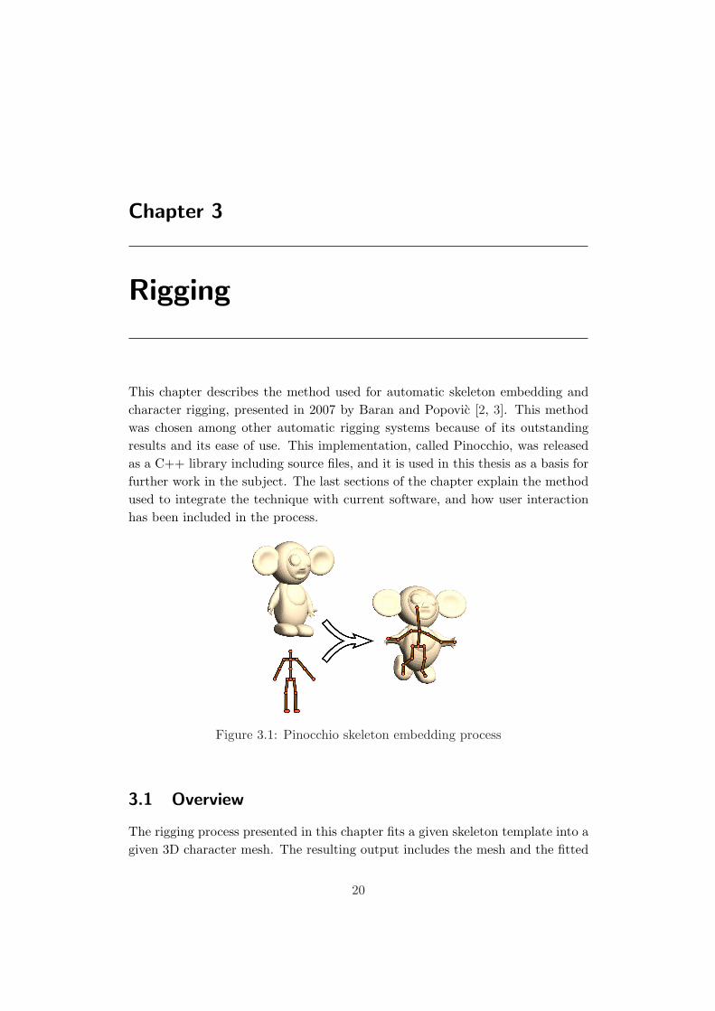
This chapter describes the method used for automatic skeleton embedding andcharacter rigging, presented in 2007 by Baran and Popovic [2, 3]. This methodwas chosen among other automatic rigging systems because of its outstandingresults and its ease of use. This implementation, called Pinocchio, was releasedas a C++ library including source files, and it is used in this thesis as a basis forfurther work in the subject. The last sections of the chapter explain the methodused to integrate the technique with current software, and how user interactionhas been included in the process.
Figure 3.1: Pinocchio skeleton embedding process
3.1 Overview
The rigging process presented in this chapter fits a given skeleton template into agiven 3D character mesh. The resulting output includes the mesh and the fitted
20
CHAPTER 3. RIGGING 21
and rigged skeleton, saved in a well known file format in order to allow furtherediting and animation in popular 3D software. Figure 3.1 represents this processgraphically. For simplification of the embedding, there are some requirementsfor the input data. The character must be a single connected mesh. Also, theskeleton and mesh must be in a similar pose and orientation, and should havesimilar proportions. Size differences between the skeleton and the mesh do notaffect the result, as a rescaling is always applied to fit inside a unit cube.
The algorithm first finds an optimal skeleton embeddings fitted into the inputmesh. This new skeleton maintains the same structure and roughly the same poseas the input skeleton. Afterwards, it computes the attachment of the new skeletonto the skin, and saves the result.
3.2 Skeleton Embedding
Given a character mesh and a template skeleton Pinocchio adjusts the skeletonto fit inside the model, by resizing and positioning its bones and joints. Thisadjustment is made by treating the issue as an optimization problem, the objec-tive of which is to compute the skeleton adjustment that fits better inside thecharacter while maintaining as much as possible its resemblance with the origi-nal skeleton. Solving this using continuous optimization is infeasible, since for askeleton with n joints this would mean solving a 3n-dimensional problem with acomplex objective function.
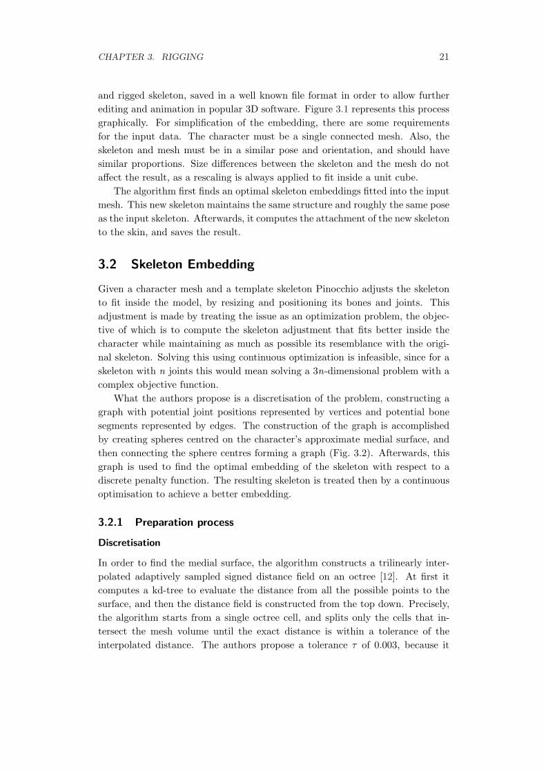
What the authors propose is a discretisation of the problem, constructing agraph with potential joint positions represented by vertices and potential bonesegments represented by edges. The construction of the graph is accomplishedby creating spheres centred on the character’s approximate medial surface, andthen connecting the sphere centres forming a graph (Fig. 3.2). Afterwards, thisgraph is used to find the optimal embedding of the skeleton with respect to adiscrete penalty function. The resulting skeleton is treated then by a continuousoptimisation to achieve a better embedding.
3.2.1 Preparation process
Discretisation
In order to find the medial surface, the algorithm constructs a trilinearly inter-polated adaptively sampled signed distance field on an octree [12]. At first itcomputes a kd-tree to evaluate the distance from all the possible points to thesurface, and then the distance field is constructed from the top down. Precisely,the algorithm starts from a single octree cell, and splits only the cells that in-tersect the mesh volume until the exact distance is within a tolerance of theinterpolated distance. The authors propose a tolerance τ of 0.003, because it
CHAPTER 3. RIGGING 22
Figure 3.2: Approximate Medial Surface, Packed Spheres, and Computed Graph.
presents the best relation between speed and precision. The distance field is thenused to compute an approximate medial surface (Fig. 3.2, left image). To ac-complish this, the octree is traversed, inspecting the nearby points for each faceof each cell and computing the gradient vectors for their adjacent cells. Thesepoints are added to the medial surface only if the vectors form an angle of morethan 120◦, in order to only adding those points in which the skeleton is moreprobably to be placed. In addition, points within a distance to the surface minorthan 2τ are also discarded for the same reason.
Once the medial surface is created, its points are sorted by their distance to thesurface and used to calculate the packed spheres, starting with the points whichare farther from the surface. If the current point is outside all the previouslyadded spheres a new sphere centred at the point is added, using as a radius thedistance to the surface. This way, the resulting spheres will be the largest ones,and no sphere will contain other sphere centres (Fig. 3.2, centre image).
Finally, the graph of potential joint and bone positions is constructed byconnecting sphere centres. An edge is added between two spheres if the spheresintersect. An additional condition has been used to add spheres that do notintersect but are important to the structure. This condition is that the distancefrom any point of the edge to the surface must be at least half of the radius ofthe smaller sphere, and the additional edge must be in the Gabriel graph [13] ofthe sphere centres. This way, spheres that do not intersect but are necessary willbe added, as seen in Figure 3.2 (centre and right) with the neck and left shoulderspheres, which do not intersect but an edge between them is created.
Before proceeding to the embedding step, Pinocchio performs a precomputa-tion of the shortest paths between all pairs of vertices in the graph of potentialjoint positions.
Simplifications
The graph of potential joint positions will be used in the next step of the processto fit the skeleton into the mesh. However, since the given skeleton may have an
CHAPTER 3. RIGGING 23
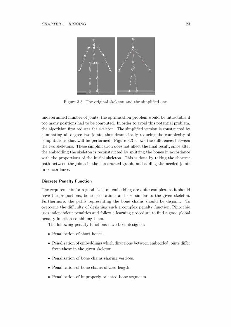
Figure 3.3: The original skeleton and the simplified one.
undetermined number of joints, the optimisation problem would be intractable iftoo many positions had to be computed. In order to avoid this potential problem,the algorithm first reduces the skeleton. The simplified version is constructed byeliminating all degree two joints, thus dramatically reducing the complexity ofcomputations that will be performed. Figure 3.3 shows the differences betweenthe two skeletons. These simplification does not affect the final result, since afterthe embedding the skeleton is reconstructed by splitting the bones in accordancewith the proportions of the initial skeleton. This is done by taking the shortestpath between the joints in the constructed graph, and adding the needed jointsin concordance.
Discrete Penalty Function
The requirements for a good skeleton embedding are quite complex, as it shouldhave the proportions, bone orientations and size similar to the given skeleton.Furthermore, the paths representing the bone chains should be disjoint. Toovercome the difficulty of designing such a complex penalty function, Pinocchiouses independent penalties and follow a learning procedure to find a good globalpenalty function combining them.
The following penalty functions have been designed:
• Penalisation of short bones.
• Penalisation of embeddings which directions between embedded joints differfrom those in the given skeleton.
• Penalisation of bone chains sharing vertices.
• Penalisation of bone chains of zero length.
• Penalisation of improperly oriented bone segments.
CHAPTER 3. RIGGING 24
• Penalisation of degree-one joints that are not embedded farthest from theirparent.
• Penalisation of joints that are close to each other but are not close in thegraph hierarchy.
The global penalty function f is a linear combination of these k simple penaltyfunctions: f(V ) =
∑ki=1 γibi(V ), where γi represents the weight that the penalty
function bi(V ) has been given by the learning procedure, being V the tuple ofvertices of the skeleton.
The learning procedure to assign the weights to each penalty function is basedon the theory of support vector machines [6]. A full description of the learningprocedure used in the finding of the global penalty function can be found in [2].
3.2.2 Embedding process
Discrete Embedding
It is computationally difficult to compute a discrete embedding that minimisesthe general penalty function. To solve this problem the authors propose the useof an estimation of a lower bound on the function from a partial embedding, anduse a branch-and-bound method to extend the embedding. A priority queue isused to keep the partial embeddings ordered by their lower bound estimates. Thebest partial embedding is taken from the queue at every step, extending it to thenext joint, and pushing the result or results back to the queue. In this manner,the first complete embedding taken from the queue is the optimal one. This isbasically the A* algorithm on the tree of possible embeddings.
Embedding Optimisation
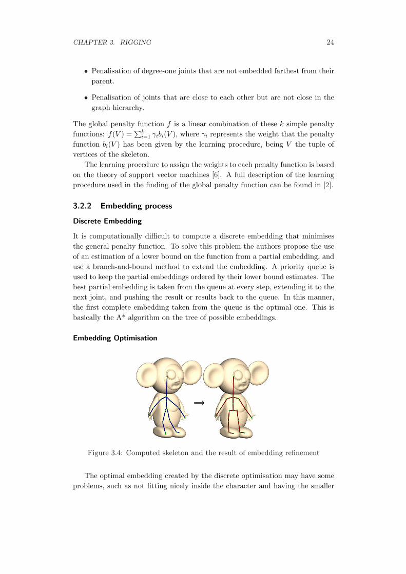
Figure 3.4: Computed skeleton and the result of embedding refinement
The optimal embedding created by the discrete optimisation may have someproblems, such as not fitting nicely inside the character and having the smaller
CHAPTER 3. RIGGING 25
bones incorrectly oriented. The latter happens because these small bones do notinfluence enough when the optimisation is run. A refinement step with a simplepenalty function solves these problems in most of the cases. Figure 3.4 shows aresult of the refinement, which is found by using a gradient descent method.
3.3 Skin Attachment
Once the skeleton is placed inside the model, it needs to be attached to the skinso when a joint is rotated or translated the mesh acts accordingly. To this end,is necessary to compute the weights of the bones for each vertex.
Some conditions have to be met in order for the weights to be correct:
• The weights should be independent of the mesh resolution.
• The distribution of these weights should be smooth.
• The width of a transition between two bones meeting at a joint should beroughly proportional to the distance from the joint to the surface.
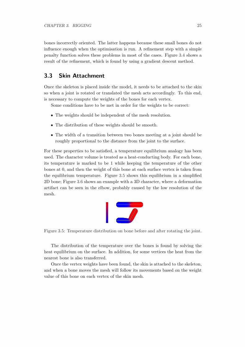
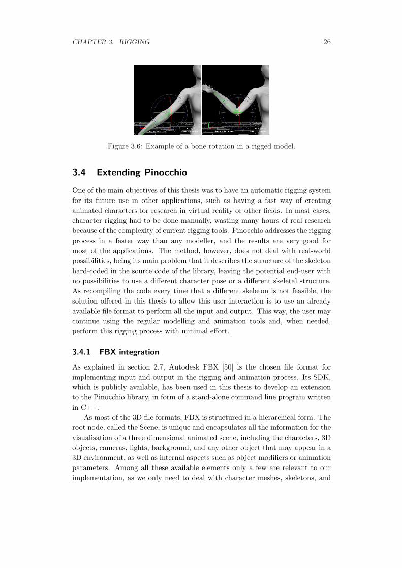
For these properties to be satisfied, a temperature equilibrium analogy has beenused. The character volume is treated as a heat-conducting body. For each bone,its temperature is marked to be 1 while keeping the temperature of the otherbones at 0, and then the weight of this bone at each surface vertex is taken fromthe equilibrium temperature. Figure 3.5 shows this equilibrium in a simplified2D bone; Figure 3.6 shows an example with a 3D character, where a deformationartifact can be seen in the elbow, probably caused by the low resolution of themesh.
Figure 3.5: Temperature distribution on bone before and after rotating the joint.
The distribution of the temperature over the bones is found by solving theheat equilibrium on the surface. In addition, for some vertices the heat from thenearest bone is also transferred.
Once the vertex weights have been found, the skin is attached to the skeleton,and when a bone moves the mesh will follow its movements based on the weightvalue of this bone on each vertex of the skin mesh.
CHAPTER 3. RIGGING 26
Figure 3.6: Example of a bone rotation in a rigged model.
3.4 Extending Pinocchio
One of the main objectives of this thesis was to have an automatic rigging systemfor its future use in other applications, such as having a fast way of creatinganimated characters for research in virtual reality or other fields. In most cases,character rigging had to be done manually, wasting many hours of real researchbecause of the complexity of current rigging tools. Pinocchio addresses the riggingprocess in a faster way than any modeller, and the results are very good formost of the applications. The method, however, does not deal with real-worldpossibilities, being its main problem that it describes the structure of the skeletonhard-coded in the source code of the library, leaving the potential end-user withno possibilities to use a different character pose or a different skeletal structure.As recompiling the code every time that a different skeleton is not feasible, thesolution offered in this thesis to allow this user interaction is to use an alreadyavailable file format to perform all the input and output. This way, the user maycontinue using the regular modelling and animation tools and, when needed,perform this rigging process with minimal effort.
3.4.1 FBX integration
As explained in section 2.7, Autodesk FBX [50] is the chosen file format forimplementing input and output in the rigging and animation process. Its SDK,which is publicly available, has been used in this thesis to develop an extensionto the Pinocchio library, in form of a stand-alone command line program writtenin C++.
As most of the 3D file formats, FBX is structured in a hierarchical form. Theroot node, called the Scene, is unique and encapsulates all the information for thevisualisation of a three dimensional animated scene, including the characters, 3Dobjects, cameras, lights, background, and any other object that may appear in a3D environment, as well as internal aspects such as object modifiers or animationparameters. Among all these available elements only a few are relevant to ourimplementation, as we only need to deal with character meshes, skeletons, and
CHAPTER 3. RIGGING 27
their attachment.
3.4.2 User interaction
The program that has been developed is thought as a helping software for re-searchers that work with 3D characters, obtained either by body scanning or bymodelling. These avatars need to be animated, and possibly this animation willcome from motion capture.
This situation led to the design a system that may receive different kinds ofmodels as well as different types of skeletons. In addition, it must allow some kindof user guidance of the process, in order to fix possible deficiencies when dealingwith a specific model or skeleton. The developed software allows the input of askeleton in FBX format plus a character mesh, and its process is the following.
• The skeleton is parsed and converted into the internal format of the Pinoc-chio library. The mesh is also passed to the library.
• The skeleton embedding process is executed. After this step the skeleton isfitted into the character mesh.
• At this point the process is paused. An intermediate output containing themesh and the fitted skeleton is handed to the user in FBX format. Theprogram waits for the user to confirm this intermediate state, or to modifythe fitting if there is some problem.
• The FBX file is re-loaded in order to incorporate any modifications madeby the user.
• The rigging step is executed. The result containing the rigged mesh is savedin a different FBX file, for if the user wants to change something and rerunonly the rigging step.
As seen, this application can be used as a rigging method for relieving the hardwork, allowing to spend quality time working with the usual tools. This is asimplified version of the application behaviour, as it not includes the clothesprocessing. In the next chapter the modifications made in order to include theclothes are described.
3.5 Summary
In this chapter a description of the Pinocchio rigging library has been presented.The method creates a rigging for the wanted mesh, but does not allow much userinteraction. This interaction is achieved by the software described in the lastsection, which integrates the powerful rigging method with the common tools auser may need, plus allowing some interaction with the process.
CHAPTER 3. RIGGING 28
However, the resulting character is naked, as the process detailed in thischapter only works with simple connected meshes. Hence, a method for addingvirtual clothes to the character may be needed. In the next chapter such a methodis reviewed.
Chapter 4
Clothing
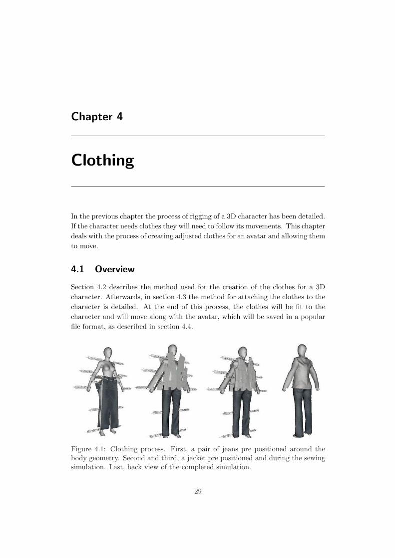
In the previous chapter the process of rigging of a 3D character has been detailed.If the character needs clothes they will need to follow its movements. This chapterdeals with the process of creating adjusted clothes for an avatar and allowing themto move.
4.1 Overview
Section 4.2 describes the method used for the creation of the clothes for a 3Dcharacter. Afterwards, in section 4.3 the method for attaching the clothes to thecharacter is detailed. At the end of this process, the clothes will be fit to thecharacter and will move along with the avatar, which will be saved in a popularfile format, as described in section 4.4.
Figure 4.1: Clothing process. First, a pair of jeans pre positioned around thebody geometry. Second and third, a jacket pre positioned and during the sewingsimulation. Last, back view of the completed simulation.
29
CHAPTER 4. CLOTHING 30
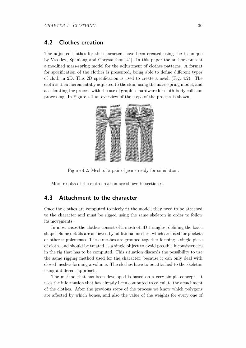
4.2 Clothes creation
The adjusted clothes for the characters have been created using the techniqueby Vassilev, Spanlang and Chrysanthou [41]. In this paper the authors presenta modified mass-spring model for the adjustment of clothes patterns. A formatfor specification of the clothes is presented, being able to define different typesof cloth in 2D. This 2D specification is used to create a mesh (Fig. 4.2). Thecloth is then incrementally adjusted to the skin, using the mass-spring model, andaccelerating the process with the use of graphics hardware for cloth-body collisionprocessing. In Figure 4.1 an overview of the steps of the process is shown.
Figure 4.2: Mesh of a pair of jeans ready for simulation.
More results of the cloth creation are shown in section 6.
4.3 Attachment to the character
Once the clothes are computed to nicely fit the model, they need to be attachedto the character and must be rigged using the same skeleton in order to followits movements.
In most cases the clothes consist of a mesh of 3D triangles, defining the basicshape. Some details are achieved by additional meshes, which are used for pocketsor other supplements. These meshes are grouped together forming a single pieceof cloth, and should be treated as a single object to avoid possible inconsistenciesin the rig that has to be computed. This situation discards the possibility to usethe same rigging method used for the character, because it can only deal withclosed meshes forming a volume. The clothes have to be attached to the skeletonusing a different approach.
The method that has been developed is based on a very simple concept. Ituses the information that has already been computed to calculate the attachmentof the clothes. After the previous steps of the process we know which polygonsare affected by which bones, and also the value of the weights for every one of
CHAPTER 4. CLOTHING 31
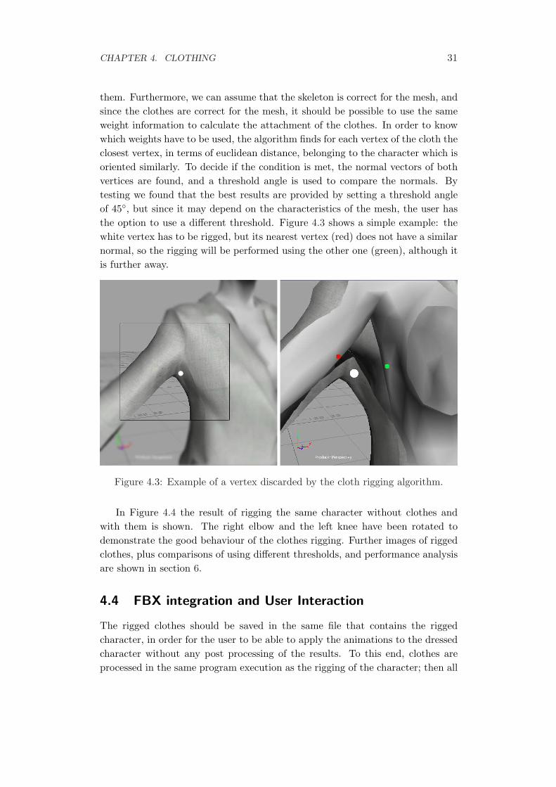
them. Furthermore, we can assume that the skeleton is correct for the mesh, andsince the clothes are correct for the mesh, it should be possible to use the sameweight information to calculate the attachment of the clothes. In order to knowwhich weights have to be used, the algorithm finds for each vertex of the cloth theclosest vertex, in terms of euclidean distance, belonging to the character which isoriented similarly. To decide if the condition is met, the normal vectors of bothvertices are found, and a threshold angle is used to compare the normals. Bytesting we found that the best results are provided by setting a threshold angleof 45◦, but since it may depend on the characteristics of the mesh, the user hasthe option to use a different threshold. Figure 4.3 shows a simple example: thewhite vertex has to be rigged, but its nearest vertex (red) does not have a similarnormal, so the rigging will be performed using the other one (green), although itis further away.
Figure 4.3: Example of a vertex discarded by the cloth rigging algorithm.
In Figure 4.4 the result of rigging the same character without clothes andwith them is shown. The right elbow and the left knee have been rotated todemonstrate the good behaviour of the clothes rigging. Further images of riggedclothes, plus comparisons of using different thresholds, and performance analysisare shown in section 6.
4.4 FBX integration and User Interaction
The rigged clothes should be saved in the same file that contains the riggedcharacter, in order for the user to be able to apply the animations to the dressedcharacter without any post processing of the results. To this end, clothes areprocessed in the same program execution as the rigging of the character; then all
CHAPTER 4. CLOTHING 32
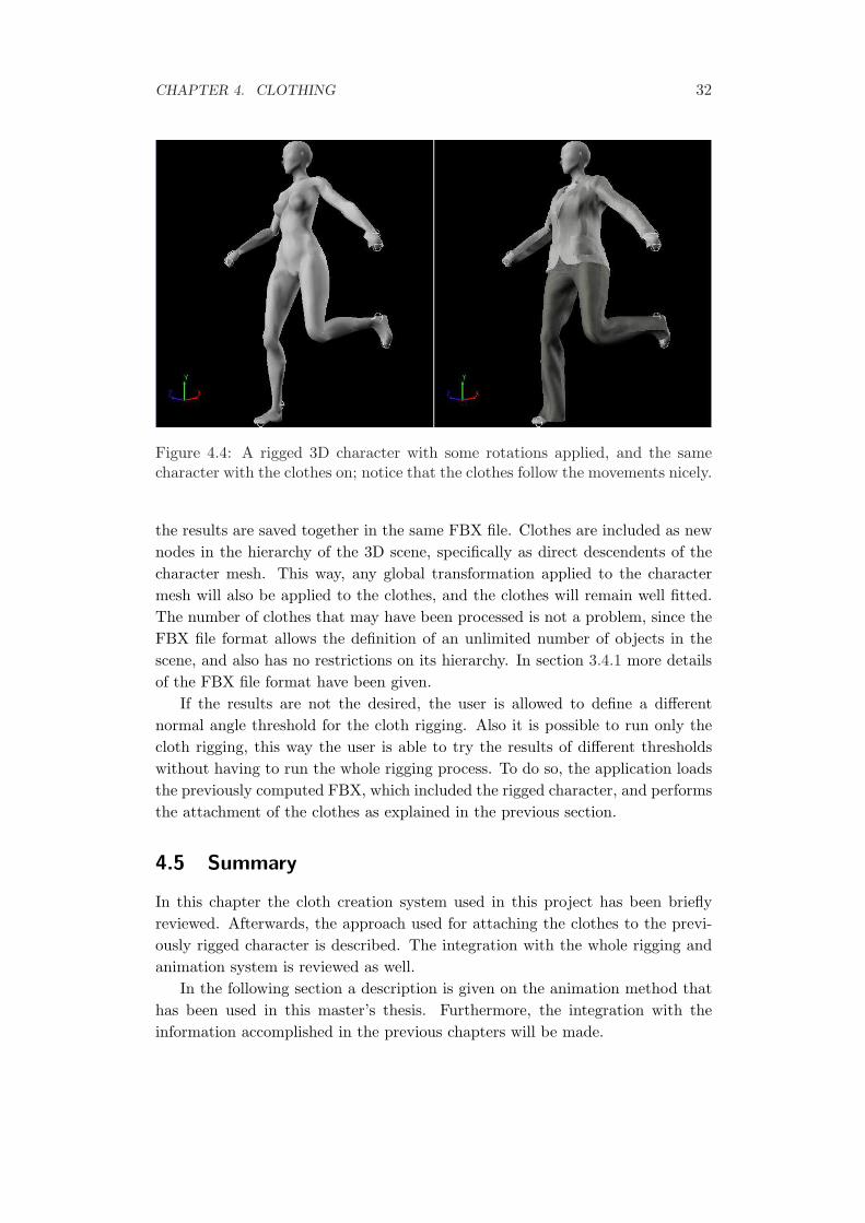
Figure 4.4: A rigged 3D character with some rotations applied, and the samecharacter with the clothes on; notice that the clothes follow the movements nicely.
the results are saved together in the same FBX file. Clothes are included as newnodes in the hierarchy of the 3D scene, specifically as direct descendents of thecharacter mesh. This way, any global transformation applied to the charactermesh will also be applied to the clothes, and the clothes will remain well fitted.The number of clothes that may have been processed is not a problem, since theFBX file format allows the definition of an unlimited number of objects in thescene, and also has no restrictions on its hierarchy. In section 3.4.1 more detailsof the FBX file format have been given.
If the results are not the desired, the user is allowed to define a differentnormal angle threshold for the cloth rigging. Also it is possible to run only thecloth rigging, this way the user is able to try the results of different thresholdswithout having to run the whole rigging process. To do so, the application loadsthe previously computed FBX, which included the rigged character, and performsthe attachment of the clothes as explained in the previous section.
4.5 Summary
In this chapter the cloth creation system used in this project has been brieflyreviewed. Afterwards, the approach used for attaching the clothes to the previ-ously rigged character is described. The integration with the whole rigging andanimation system is reviewed as well.
In the following section a description is given on the animation method thathas been used in this master’s thesis. Furthermore, the integration with theinformation accomplished in the previous chapters will be made.
Chapter 5
Animation
5.1 Overview
This chapter presents the animation method that has been used to integrate withthe results of the rigging and clothing of 3D characters. The chosen technique ismotion-capture –often abbreviated mocap– because of its realistic results and itseasy integration with current animation software.
5.2 OptiTrack
OptiTrack [32] is a complete and affordable motion-capture system. It is com-mercialised by NaturalPoint, a company specialised in tracking systems, whichalso offers other solutions such as a head-tracking display for video game playersand an infrared eye-tracking system for PCs. Many other manufacturers, likeVicon, also offer motion-capture systems, but to our knowledge OptiTrack is thesystem with a better quality-price ratio.
5.2.1 System Setup
The OptiTrack system is formed by a varying number of USB cameras connectedto a personal computer and a set of reflecting markers which will be worn bythe subject. The recommended configuration is of no less than 6 cameras, andoffering optimal results with 8 cameras or more, but it may depend in a greatmeasure on the conditions of the setup scenario, as well as possible reflectionsor blocking objects, which may have a negative effect on the precision of theanimations. The cameras are able to capture infrared light as well as black andwhite images. The main difference from other systems is that the cameras have asmall CPU which allows them to perform live image processing such as applying
33
CHAPTER 5. ANIMATION 34
a threshold on the image, or blocking certain areas where reflections are present.The goal is to have a final image where the points to be tracked (markers) areeasily recognisable, and so the only things that have to be transferred to the PCare the 2D positions of the markers. This feature allows several cameras to beconnected to a single PC, as very low bandwidth is used. In addition the PCdoes not need to process any image, only direct points, so the processor is morecapable of dealing with the animation. The system includes a specific software togather the information given by the cameras and compute the movements, andthis application is also used for calibrating the cameras before starting the actualcapture.
First of all, the cameras have to be distributed throughout the room, takingcare in avoiding as much as possible blocking objects and cameras seeing othercameras, and trying to avoid points seen by only one or two cameras. In thisthesis a setup of 8 cameras has been used.
5.2.2 Calibration
Once the cameras are positioned and connected to the PC, they may need someadjustments. The software provides a tool for reviewing what is seen by eachcamera, allowing to adjust some parameters, such as ignoring some invalid pointscaused by reflections, or tweak the image processing made by the cameras. Af-terwards, the OptiTrack software asks to perform a calibration process, in orderfor the PC to learn interpreting the data which it receives from all the cameras.In Figure 5.1 an overview of the calibration process is shown. First of all, theuser has to move a single marker around the room, trying to reach all the possi-ble points seen by each camera. This process is helped by an interface showingthe path drawn so far (Fig. 5.1 top). The PC gathers all the data received andperform a series of calculations that will indicate the relative position of all thecameras. Once these positions are known, a reference system must be created,in order for the software to know where the floor is and how is it oriented withrespect to the cameras. This is done by placing three markers on the floor form-ing a triangle (Fig. 5.1 centre). The last step is the reviewing of the calibrationprocess, in which the software shows a picture of all the camera frustums andthe effective motion capture volume (Fig. 5.1 bottom). In this step the user isallowed to move the markers through the scene to confirm that the positions arewell computed.
5.2.3 Motion Capture
Once the system is calibrated, the user dresses in the mocap suit and places allthe markers on it, guided by the software. Then a skeleton calibration needsto be done in order for the system to know the physical characteristics of the
CHAPTER 5. ANIMATION 35
Figure 5.1: Three steps of the OptiTrack calibration process
CHAPTER 5. ANIMATION 36
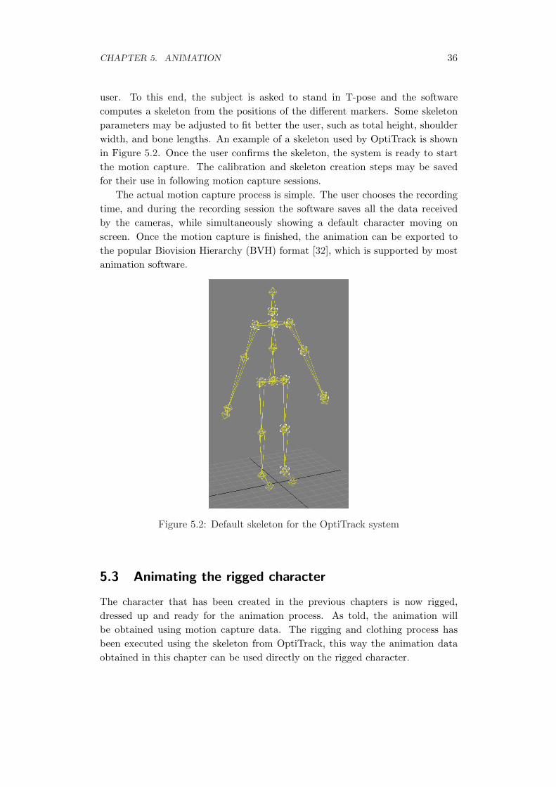
user. To this end, the subject is asked to stand in T-pose and the softwarecomputes a skeleton from the positions of the different markers. Some skeletonparameters may be adjusted to fit better the user, such as total height, shoulderwidth, and bone lengths. An example of a skeleton used by OptiTrack is shownin Figure 5.2. Once the user confirms the skeleton, the system is ready to startthe motion capture. The calibration and skeleton creation steps may be savedfor their use in following motion capture sessions.
The actual motion capture process is simple. The user chooses the recordingtime, and during the recording session the software saves all the data receivedby the cameras, while simultaneously showing a default character moving onscreen. Once the motion capture is finished, the animation can be exported tothe popular Biovision Hierarchy (BVH) format [32], which is supported by mostanimation software.
Figure 5.2: Default skeleton for the OptiTrack system
5.3 Animating the rigged character
The character that has been created in the previous chapters is now rigged,dressed up and ready for the animation process. As told, the animation willbe obtained using motion capture data. The rigging and clothing process hasbeen executed using the skeleton from OptiTrack, this way the animation dataobtained in this chapter can be used directly on the rigged character.
CHAPTER 5. ANIMATION 37
The motion capture system that has been used allows different methods ofusing the animation data in any system:
• Data may be exported to BVH file format, and then imported into any 3Danimation software.
• An OptiTrack plug-in for MotionBuilder is available, allowing real-timemotion capture with a custom character.
• A Software Development Kit (SDK) offering animation streaming data isalso available. Using this library, any software is able to obtain the ani-mation data in real-time during motion capture. Applications such as im-mersive virtual environments may use this SDK for implementing real-timefeedback to the user.
The animation software that has been used to animate the character is Mo-tionBuilder [48]. This application makes use of a predefined complex skeletalstructure to which all the movements are applied, and offers a mapping tool inorder to transfer the movements to any custom skeleton. The skeleton used byMotionBuilder is very complete in order to allow the maximum number of detailswhen animating the character, but also allows the use of a subset of the availablejoints. This is what has been done in this thesis: the rigged character processedusing the OptiTrack skeleton has been mapped to the MotionBuilder controlskeleton, and the animation from motion capture has been applied straightfor-ward. Results and analysis of this animation step are shown in chapter 6.
5.4 Summary
In this chapter a review of a popular motion capture system was presented, anddetails on its usage were given. The integration of animations with the workmade on previous chapters was described.
In the next chapter results and tests of the automatic animation system willbe shown.
Chapter 6
Results
This chapter presents some results obtained using the method described through-out the whole thesis. Some pictures of the different steps of the process are shown.In addition, some tests have been executed and its results are presented.
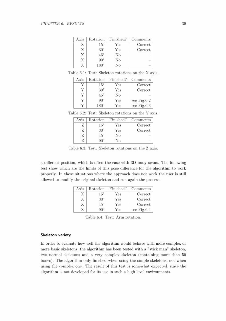
This thesis aims to provide an easy-to-use tool for non-professional modellers.To this end, the process has been tested from a practical point of view, with theobjective to discover its limits. Following this criteria, the following tests havebeen made on the character rigging step:
• Orientation limits. The input skeleton is rotated previous to the processingin different angles and axis.
• Pose variation limits. Extremities are rotated so the initial pose of theskeleton differs from the character one.
• Possibility to use different skeletons. From a basic ”stick man” to a verycomplex skeleton have been tested.
Results from the clothing step are also reviewed.
Orientation limits
The input skeleton may not be always oriented exactly like the character mesh. Inorder to know which are the limits in which a good embedding is found, differentorientations of the same skeleton have been tried. In tables 6.1 to 6.3 the resultsare shown.
Pose variation
The pose that is normally used for the skeletons is the so-called T-pose. However,it is possible that the mesh is not in this exact pose, but may have the arms in
38
CHAPTER 6. RESULTS 39
Axis Rotation Finished? CommentsX 15◦ Yes CorrectX 30◦ Yes CorrectX 45◦ No –X 90◦ No –X 180◦ No –
Table 6.1: Test: Skeleton rotations on the X axis.
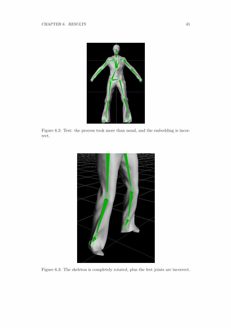
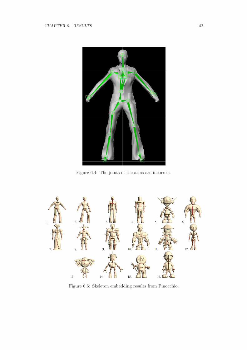
Axis Rotation Finished? CommentsY 15◦ Yes CorrectY 30◦ Yes CorrectY 45◦ No –Y 90◦ Yes see Fig.6.2Y 180◦ Yes see Fig.6.3
Table 6.2: Test: Skeleton rotations on the Y axis.
Axis Rotation Finished? CommentsZ 15◦ Yes CorrectZ 30◦ Yes CorrectZ 45◦ No –Z 90◦ No –
Table 6.3: Test: Skeleton rotations on the Z axis.
a different position, which is often the case with 3D body scans. The followingtest show which are the limits of this pose difference for the algorithm to workproperly. In those situations where the approach does not work the user is stillallowed to modify the original skeleton and run again the process.
In order to evaluate how well the algorithm would behave with more complex ormore basic skeletons, the algorithm has been tested with a ”stick man” skeleton,two normal skeletons and a very complex skeleton (containing more than 50bones). The algorithm only finished when using the simple skeletons, not whenusing the complex one. The result of this test is somewhat expected, since thealgorithm is not developed for its use in such a high level environments.
CHAPTER 6. RESULTS 40
Clothing
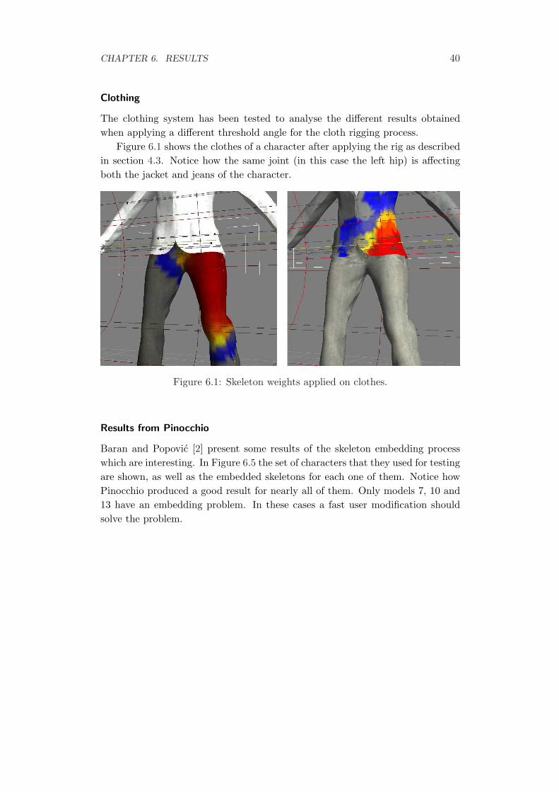
The clothing system has been tested to analyse the different results obtainedwhen applying a different threshold angle for the cloth rigging process.
Figure 6.1 shows the clothes of a character after applying the rig as describedin section 4.3. Notice how the same joint (in this case the left hip) is affectingboth the jacket and jeans of the character.
Figure 6.1: Skeleton weights applied on clothes.
Results from Pinocchio
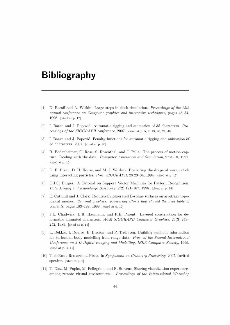
Baran and Popovic [2] present some results of the skeleton embedding processwhich are interesting. In Figure 6.5 the set of characters that they used for testingare shown, as well as the embedded skeletons for each one of them. Notice howPinocchio produced a good result for nearly all of them. Only models 7, 10 and13 have an embedding problem. In these cases a fast user modification shouldsolve the problem.
CHAPTER 6. RESULTS 41
Figure 6.2: Test: the process took more than usual, and the embedding is incor-rect.
Figure 6.3: The skeleton is completely rotated, plus the feet joints are incorrect.
CHAPTER 6. RESULTS 42
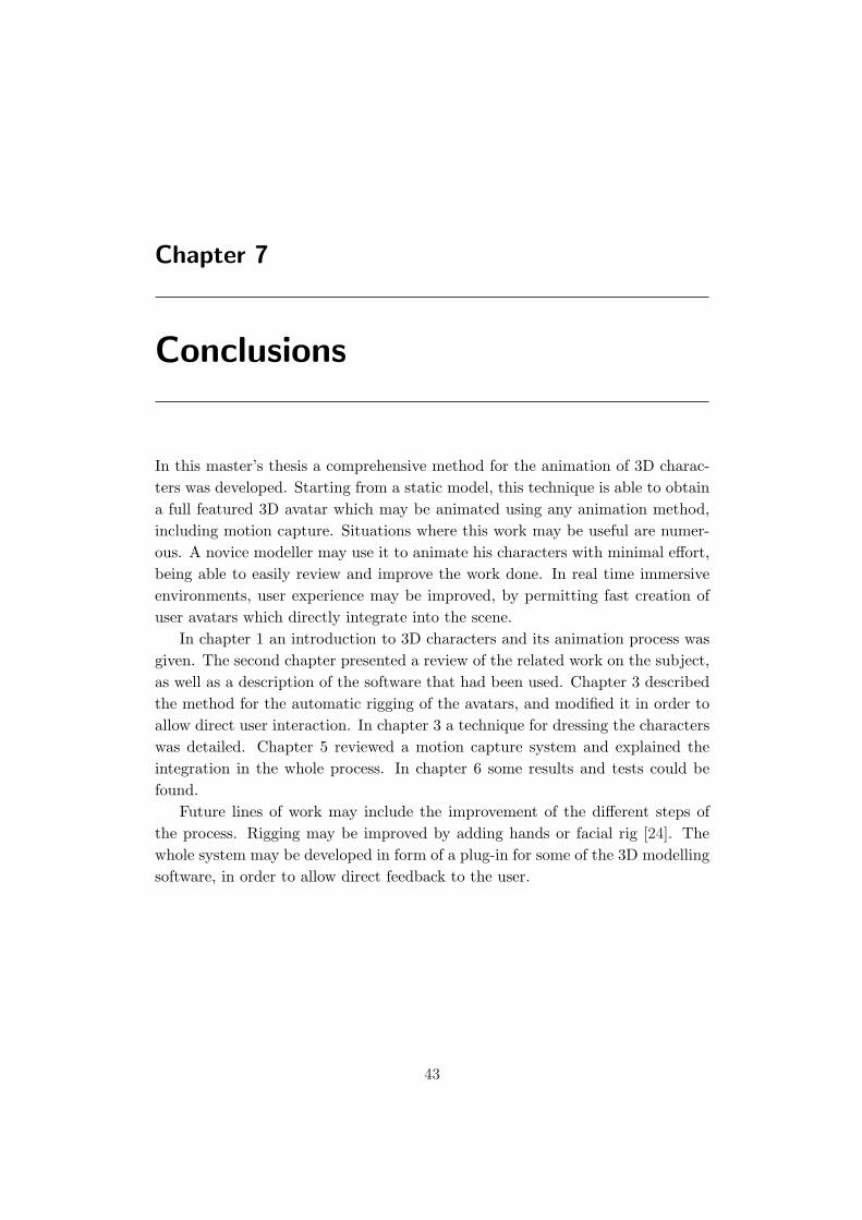
Figure 6.4: The joints of the arms are incorrect.
Figure 6.5: Skeleton embedding results from Pinocchio.
Chapter 7
Conclusions
In this master’s thesis a comprehensive method for the animation of 3D charac-ters was developed. Starting from a static model, this technique is able to obtaina full featured 3D avatar which may be animated using any animation method,including motion capture. Situations where this work may be useful are numer-ous. A novice modeller may use it to animate his characters with minimal effort,being able to easily review and improve the work done. In real time immersiveenvironments, user experience may be improved, by permitting fast creation ofuser avatars which directly integrate into the scene.
In chapter 1 an introduction to 3D characters and its animation process wasgiven. The second chapter presented a review of the related work on the subject,as well as a description of the software that had been used. Chapter 3 describedthe method for the automatic rigging of the avatars, and modified it in order toallow direct user interaction. In chapter 3 a technique for dressing the characterswas detailed. Chapter 5 reviewed a motion capture system and explained theintegration in the whole process. In chapter 6 some results and tests could befound.
Future lines of work may include the improvement of the different steps ofthe process. Rigging may be improved by adding hands or facial rig [24]. Thewhole system may be developed in form of a plug-in for some of the 3D modellingsoftware, in order to allow direct feedback to the user.
43
Bibliography
[1] D. Baraff and A. Witkin. Large steps in cloth simulation. Proceedings of the 25thannual conference on Computer graphics and interactive techniques, pages 43–54,1998. [cited at p. 17]
[2] I. Baran and J. Popovic. Automatic rigging and animation of 3d characters. Pro-ceedings of the SIGGRAPH conference, 2007. [cited at p. 5, 7, 13, 20, 24, 40]
[3] I. Baran and J. Popovic. Penalty functions for automatic rigging and animation of3d characters. 2007. [cited at p. 20]
[4] B. Bodenheimer, C. Rose, S. Rosenthal, and J. Pella. The process of motion cap-ture: Dealing with the data. Computer Animation and Simulation, 97:3–18, 1997.[cited at p. 15]
[5] D. E. Breen, D. H. House, and M. J. Wozhny. Predicting the drape of woven clothusing interacting particles. Proc. SIGGRAPH, 28:23–34, 1994. [cited at p. 17]
[6] C.J.C. Burges. A Tutorial on Support Vector Machines for Pattern Recognition.Data Mining and Knowledge Discovery, 2(2):121–167, 1998. [cited at p. 24]
[7] E. Catmull and J. Clark. Recursively generated B-spline surfaces on arbitrary topo-logical meshes. Seminal graphics: poineering efforts that shaped the field table ofcontents, pages 183–188, 1998. [cited at p. 10]
[8] J.E. Chadwick, D.R. Haumann, and R.E. Parent. Layered construction for de-formable animated characters. ACM SIGGRAPH Computer Graphics, 23(3):243–252, 1989. [cited at p. 15]
[9] L. Dekker, I. Douros, B. Buxton, and P. Treleaven. Building symbolic informationfor 3d human body modelling from range data. Proc. of the Second InternationalConference on 3-D Digital Imaging and Modelling, IEEE Computer Society, 1999.[cited at p. 4, 11]
[10] T. deRose. Research at Pixar. In Symposium on Geometry Processing, 2007, Invitedspeaker. [cited at p. 9]
[11] T. Disz, M. Papka, M. Pellegrino, and R. Stevens. Sharing visualization experiencesamong remote virtual environments. Proceedings of the International Workshop
44
BIBLIOGRAPHY 45
on High Performance Computing for Computer Graphics and Visualization, 1995.[cited at p. 3]
[12] S. F. Frisken, R. N. Perry, A. P. Rockwood, and T. R. Jones. Adaptively sampleddistance fields: A general representation of shape for computer graphics. Proceedingsof ACM SIGGRAPH, 2000. [cited at p. 21]
[13] K.R. Gabriel and R.R. Sokal. A new statistical approach to geographic variationanalysis. Systematic Zoology, 18(3):259–278, 1969. [cited at p. 22]
[14] M. Garau, M. Slater, D.P. Pertaub, and S. Razzaque. The responses of people tovirtual humans in an immersive virtual environment. Presence: Teleoperators &Virtual Environments, MIT Press, 2005. [cited at p. 3]
[15] C. Geiger, J. Stoecklein, F. Klompmaker, and R. Fritze. Development of an aug-mented reality game by extendinga 3D authoring system. Proceedings of the in-ternational conference on Advances in computer entertainment technology, pages230–231, 2007. [cited at p. 15]
[16] M. Gleicher. Comparing constraint-based motion editing methods. Graphical Mod-els, 2001. [cited at p. 15]
[17] J. E. Gomez. Twixt: A 3d animation system. Comp. Graphics, 1985. [cited at p. 14]
[18] T. Igarashi, S. Matsuoka, and H. Tanaka. Teddy: a sketching interface for 3dfreeform design. Proceedings of the ACM SIGGRAPH, 1999. [cited at p. 4, 10]
[19] O. A. Karpenko and J. F. Hughes. Smoothsketch: 3d free-form shapes from complexsketches. ACM Trans. Graph, 2006. [cited at p. 11]
[20] M. Kazhdan, M. Bolitho, and H. Hoppe. Poisson surface reconstruction. In SGP’06: Proceedings of the fourth Eurographics symposium on Geometry processing,pages 61–70, Aire-la-Ville, Switzerland, Switzerland, 2006. Eurographics Associa-tion. [cited at p. 11]
[21] R. Maiocchi. 3-D character animation using motion capture. 1996. [cited at p. 15]
[22] A. Nealen, T. Igarashi, O. Sorkine, and M. Alexa. Fibermesh: Designing freeformsurfaces with 3d curves. ACM Trans. Graph, 2007. [cited at p. 11]
[23] J. Oliveira, D. Zhang, B. Spanlang, and B. Buxton. Animating scanned humanmodels. Journal of WSCG, 2003. [cited at p. 12, 14]
[24] V.C.T. Orvalho, E. Zacur, and A. Susin. Transferring Facial Expressions to DifferentFace Models. Ibero-American Symposium on Computer Graphics -SIACG, 2006.[cited at p. 14, 43]
[25] L. Piegl. On NURBS: a survey. Computer Graphics and Applications, IEEE,11(1):55–71, 1991. [cited at p. 10]
[26] L.A. Piegl and W. Tiller. The Nurbs Book. Springer, 1997. [cited at p. 10]
[27] K. Pullen and C. Bregler. Motion capture assisted animation: texturing and syn-thesis. ACM Transactions on Graphics (TOG), 21(3):501–508, 2002. [cited at p. 15]
BIBLIOGRAPHY 46
[28] X. Rodrıguez-Navarro and A. Susin. Non structured meshes for cloth gpu simulationusing fem. In I. Navazo. C. Mendoza, editor, Proc. VRIPHYS’06. 3rd. Workshop inVirtual Reality, Interactions, and Physical Simulations (VRIPHYS’06)., pages 1–7.Eurographics Ed, 2006. [cited at p. 17]
[29] R. Schmidt, B. Wyvill, M. Sousa, and J. Jorge. Shapeshop: Sketch-based solidmodeling with blobtrees. Eurographics Workshop on Sketch-Based Interfaces andModeling, 2005. [cited at p. 11]
[30] M. Slater, A. Antley, A. Davison, D. Swapp, and C. Guger. A virtual reprise of theStanley Milgram Obedience Experiments. PLoS ONE, 2006. [cited at p. 3]
[31] M. Slater, M. Usoh, and A. Steed. Depth of presence in virtual environments.Presence: Teleoperators and Virtual Environments, 3(2):130–144, 1994. [cited at p. 4]
[32] Optitrack software. http://www.naturalpoint.com/optitrack/. [cited at p. 7, 33, 36]
[33] B. Spanlang, T. Frohlich, V. Descalzo, A. Antley, and M. Slater. The making of apresence experiment: Responses to virtual fire. In Annual International Workshopon Presence, pages 303–307. Presence, 2007. [cited at p. 3]
[34] B. Spanlang, T. Vassilev, J.Walters, and B. F. Buxton. A virtual clothing systemfor retail and design. Research Journal of Textile and Apparel, 9(1):74–87, Feb 2005.[cited at p. 5, 7, 17]
[35] D. Sturman. Interactive keyframe animation of 3d articulated models. SIGGRAPH. Course Notes: Computer Animation: 3D Motion Specification and Control, pages17–26, 1987. [cited at p. 14]
[36] F. Tecchia, C. Loscos, and Y. Chrysanthou. Visualizing crowds in real-time. Com-puter Graphics Forum, 2002. [cited at p. 3]
[37] D. Terzopoulos and K. Fleischer. Deformable models. The Visual Computer,4(6):306–331, 1988. [cited at p. 16]
[38] D. Terzopoulos and K. Fleischer. Modeling inelastic deformation: viscolelasticity,plasticity, fracture. Proceedings of the 15th annual conference on Computer graphicsand interactive techniques, pages 269–278, 1988. [cited at p. 16]
[39] D. Terzopoulos, J. Platt, A. Barr, and K. Fleischer. Elastically deformable models.ACM SIGGRAPH Computer Graphics, 21(4):205–214, 1987. [cited at p. 16]
[40] M. Thorne, D. Burke, and M. van de Panne. Motion doodles: an interface forsketching character motion. International Conference on Computer Graphics andInteractive Techniques, pages 424–431, 2004. [cited at p. 16]
[41] T. Vassilev, B. Spanlang, and Y. Chrysanthou. Fast cloth animation on walkingavatars. Computer Graphics Forum 20, 2001. [cited at p. 17, 30]
[42] Autodesk 3ds Max web site. http://www.autodesk.com/3dsmax/. [cited at p. 4, 9, 10]
[43] Autodesk Maya web site. http://www.autodesk.com/maya/. [cited at p. 9, 10]
[44] Blender web site. http://www.blender.org/. [cited at p. 4, 10]
BIBLIOGRAPHY 47
[45] Cal3D web site. http://home.gna.org/cal3d/. [cited at p. 18]
[46] Collada web site. http://www.collada.org/. [cited at p. 18]
[47] LightWave web site. http://www.newtek.com/lightwave/. [cited at p. 9, 10]
[48] MotionBuilder web site. http://www.autodesk.com/motionbuilder/. [cited at p. 14,
37]
[49] Second Life web site. http://secondlife.com/. [cited at p. 3]
[50] FBX web site: file format specification and Software Development Kit.http://www.alias.com/fbx/. [cited at p. 6, 7, 18, 26]
[51] C. Welman. Inverse kinematics and geometric constraints for articulated figuremanipulation. Master’s thesis, Simon Fraser University, 1993. [cited at p. 15]
[52] V.B. Zordan, A. Majkowska, B. Chiu, and M. Fast. Dynamic response for motioncapture animation. International Conference on Computer Graphics and InteractiveTechniques, pages 697–701, 2005. [cited at p. 15]