A R C H I V E S O F M E T A L L U R G Y A N D M A T E R I A L S Volume 60 2015 Issue 2 DOI: 10.1515/amm-2015-0195 G. GUMIENNY * ,] , T. GIĘTKA ** CONTINUOUS COOLING TRANSFORMATION (CCT) DIAGRAMS OF CARBIDIC NODULAR CAST IRON WYKRESY CTP c ŻELIWA SFEROIDALNEGO Z WĘGLIKAMI This work presents continuous cooling transformation diagrams for different kinds of carbidic nodular cast iron. We investigated the cast iron, chemical composition of which in nodular cast iron allows the obtainment of a metal matrix which consists of: pearlite, upper bainite and its mixture with lower bainite, ausferrite and martensite when the casts were cooled in the mold. The influence of the rate of cooling on the obtained microstructure and hardness of the casts was shown. The work describes the influence of the alloy additives on the curves of austenite decomposition in the carbidic nodular cast iron. Diagrams were plotted which enable an understanding of the kinetics of the transformations of austenite in carbidic nodular cast iron. The diagrams also indicate the possibility of obtaining pearlite, bainite, martensite and ausferrite with the established chemical composition and the wall thickness of the cast. Keywords: carbidic nodular cast iron, bainite, ausferrite, continuous cooling transformation diagrams W pracy przedstawiono wykresy CTP c różnych rodzajów żeliwa sferoidalnego z węglikami. Zbadano żeliwo o skladzie chemicznym zapewniającym uzyskanie w żeliwie sferoidalnym osnowy metalowej zlożonej z: perlitu, bainitu górnego oraz jego mieszaniny z dolnym, ausferrytu i martenzytu przy studzeniu odlewów w formie. Pokazano wplyw szybkości studzenia na uzyskiwaną mikrostrukturę i twardość odlewów. Opisano wplyw dodatków stopowych na krzywe rozpadu austenitu w żeliwie sferoidalnym z węglikami. Opracowane wykresy umożliwią poznanie kinetyki przemian austenitu w żeliwie sferoidalnym z węglikami oraz ocenę możliwości uzyskania perlitu, bainitu, martenzytu i ausferrytu przy zadanym skladzie chemicznym oraz grubości ściany odlewu. 1. Introduction Previous research on the subject indicates that in nodular non-alloy cast iron the bainitic or ausferritic microstructure can be obtained by hardening through isothermal holding in the range of austenite → bainite transformation [1, 2]. The end of isothermal holding before the beginning of carbide precipitation from carbon supersaturated austenite and ferrite produces the ausferritic microstructure. Subsequently, austem- pered ductile iron (ADI) is obtained, which is known in dif- ferent types [3]. It is used for machine units and devices used in the conditions of wear and adhesive wear. It is possible to obtain ausferrite in non-alloy cast iron only for the casts whose wall thickness is less than 8 mm [4]. In the case of casts with thicker walls, elements which increase the hardenability of the cast iron should be added. Elements such as Mo, Cr, Cu, Ni cause displacement of the curve of the beginning of austenite decomposition in the direction of the longer periods of time and that nickel has the most intensive influence. The influence of copper on austenite stability is less intensive. In order to obtain the pearlitic metal matrix, Cu and Ni are added to cast iron. For this reason the concentration of Mn is increased by a maximum of 0.8%. Chromium and molybdenum are carbide forming elements, but to some extent they dissolve in austen- ite, influencing its stability. The influence of molybdenum is also typical, in that it increases the stability of austenite in the range of its transformation to pearlite. However, it does not have an important influence on its stability in the bainitic range. The schematic influence of Mo on austenite stability in cast iron is presented in Figure 1 [5]. It follows from this that for the rate of cooling of the cast v, in cast iron without a Mo additive, the austenite is subjected to transformation into a mixture of ferrite and pearlite. How- ever, in cast iron with a Mo additive, the transformation is one into bainite or ausferrite. Obtaining the bainitic or ausfer- ritic microstructure is conditioned by the content of Mo and other alloy additives, e.g. Cu and Ni, the correct concentra- tion of which enables the obtention of the above mentioned microstructure without ferrite or pearlite inclusion [5÷9]. In order to obtain the martensitic microstructure it is necessary to add elements which increase the hardness in such a quantity that when cooling the cast in the mold, it would be possible to obtain the rate of cooling equal to, or larger than, the critical one, both in the range of austenite transformation into pearlite and into bainite. * DEPARTMENT OF MATERIALS ENGINEERING AND PRODUCTION SYSTEMS, LODZ UNIVERSITY OF TECHNOLOGY, 1/15 STEFANOWSKIEGO STR., 90-924 LÓDŹ, POLAND ** MATERIAL ENGINEERING UNIT, MECHANICAL ENGINEERING DEPARTMENT, UNIVERSITY OF TECHNOLOGY AND LIFE SCIENCE IN BYDGOSZCZ, 7 PROF. S. KALISKIEGO STR., 85-796 BYDGOSZCZ, POLAND ] Corresponding author: [email protected]
Transcript
A R C H I V E S O F M E T A L L U R G Y A N D M A T E R I A L S
Volume 60 2015 Issue 2
DOI: 10.1515/amm-2015-0195
G. GUMIENNY∗ ,], T. GIĘTKA∗∗
CONTINUOUS COOLING TRANSFORMATION (CCT) DIAGRAMS OF CARBIDIC NODULAR CAST IRON
WYKRESY CTPc ŻELIWA SFEROIDALNEGO Z WĘGLIKAMI
This work presents continuous cooling transformation diagrams for different kinds of carbidic nodular cast iron. Weinvestigated the cast iron, chemical composition of which in nodular cast iron allows the obtainment of a metal matrix whichconsists of: pearlite, upper bainite and its mixture with lower bainite, ausferrite and martensite when the casts were cooledin the mold. The influence of the rate of cooling on the obtained microstructure and hardness of the casts was shown. Thework describes the influence of the alloy additives on the curves of austenite decomposition in the carbidic nodular cast iron.Diagrams were plotted which enable an understanding of the kinetics of the transformations of austenite in carbidic nodularcast iron. The diagrams also indicate the possibility of obtaining pearlite, bainite, martensite and ausferrite with the establishedchemical composition and the wall thickness of the cast.
W pracy przedstawiono wykresy CTPc różnych rodzajów żeliwa sferoidalnego z węglikami. Zbadano żeliwo o składziechemicznym zapewniającym uzyskanie w żeliwie sferoidalnym osnowy metalowej złożonej z: perlitu, bainitu górnego orazjego mieszaniny z dolnym, ausferrytu i martenzytu przy studzeniu odlewów w formie. Pokazano wpływ szybkości studzenia nauzyskiwaną mikrostrukturę i twardość odlewów. Opisano wpływ dodatków stopowych na krzywe rozpadu austenitu w żeliwiesferoidalnym z węglikami. Opracowane wykresy umożliwią poznanie kinetyki przemian austenitu w żeliwie sferoidalnym zwęglikami oraz ocenę możliwości uzyskania perlitu, bainitu, martenzytu i ausferrytu przy zadanym składzie chemicznym orazgrubości ściany odlewu.
1. Introduction
Previous research on the subject indicates that in nodularnon-alloy cast iron the bainitic or ausferritic microstructurecan be obtained by hardening through isothermal holding inthe range of austenite → bainite transformation [1, 2]. Theend of isothermal holding before the beginning of carbideprecipitation from carbon supersaturated austenite and ferriteproduces the ausferritic microstructure. Subsequently, austem-pered ductile iron (ADI) is obtained, which is known in dif-ferent types [3]. It is used for machine units and devices usedin the conditions of wear and adhesive wear. It is possible toobtain ausferrite in non-alloy cast iron only for the casts whosewall thickness is less than 8 mm [4]. In the case of casts withthicker walls, elements which increase the hardenability of thecast iron should be added. Elements such as Mo, Cr, Cu, Nicause displacement of the curve of the beginning of austenitedecomposition in the direction of the longer periods of timeand that nickel has the most intensive influence. The influenceof copper on austenite stability is less intensive. In order toobtain the pearlitic metal matrix, Cu and Ni are added to castiron. For this reason the concentration of Mn is increased by a
maximum of 0.8%. Chromium and molybdenum are carbideforming elements, but to some extent they dissolve in austen-ite, influencing its stability. The influence of molybdenum isalso typical, in that it increases the stability of austenite inthe range of its transformation to pearlite. However, it doesnot have an important influence on its stability in the bainiticrange. The schematic influence of Mo on austenite stability incast iron is presented in Figure 1 [5].
It follows from this that for the rate of cooling of the castv, in cast iron without a Mo additive, the austenite is subjectedto transformation into a mixture of ferrite and pearlite. How-ever, in cast iron with a Mo additive, the transformation isone into bainite or ausferrite. Obtaining the bainitic or ausfer-ritic microstructure is conditioned by the content of Mo andother alloy additives, e.g. Cu and Ni, the correct concentra-tion of which enables the obtention of the above mentionedmicrostructure without ferrite or pearlite inclusion [5÷9]. Inorder to obtain the martensitic microstructure it is necessaryto add elements which increase the hardness in such a quantitythat when cooling the cast in the mold, it would be possible toobtain the rate of cooling equal to, or larger than, the criticalone, both in the range of austenite transformation into pearliteand into bainite.
∗ DEPARTMENT OF MATERIALS ENGINEERING AND PRODUCTION SYSTEMS, LODZ UNIVERSITY OF TECHNOLOGY, 1/15 STEFANOWSKIEGO STR., 90-924 ŁÓDŹ, POLAND∗∗ MATERIAL ENGINEERING UNIT, MECHANICAL ENGINEERING DEPARTMENT, UNIVERSITY OF TECHNOLOGY AND LIFE SCIENCE IN BYDGOSZCZ, 7 PROF. S. KALISKIEGO STR.,85-796 BYDGOSZCZ, POLAND] Corresponding author: [email protected]
706
Fig. 1. The scheme of molybdenum influence on the curves of thebeginning of austenite decomposition in cast iron [4]
Research detailing time-temperature-transformation dia-grams of the nodular cast iron is presented, among others, inwork [10]. On the basis of TTT diagrams systems that supportthe production of ductile iron or other alloys are created [11].The continuous cooling transformation diagrams for carbidicnodular cast iron have not been drawn so far. It is for thisreason the aim of this research was to devise continuous cool-ing transformation diagrams of carbidic nodular cast iron andto present the influence of molybdenum, chromium, nickeland copper on the curves of decomposition of austenite inthe tested cast iron. The continuous cooling transformationdiagrams in this paper should be helpful when selecting thechemical composition of nodular cast iron for obtaining theunwrought (without thermal treatment) different microstruc-ture of the metal matrix.
2. Methodology of the research
The cast iron used in the research was melted in an in-duction furnace with the capacity of 30 kg. The nodularisingwas carried out using the Inmold method which is based onthe use of master alloy in the gate assembly of the mold.
The chemical composition of certain types of cast ironwas tested on an emissive spectrometer with spark excita-tion SPECTROMAXx by SPECTRO Analytical InstrumentsGmbH (see Table 1).
The maximum concentration of P and S was 0.04% and0.01% respectively.
The microstructure of cast iron was tested on the polishedsections etched by nital under ×1000 magnification using anEclipse MA200 metallographic microscope by Nikon.
The surface percentage was investigated using the NISElements BR software designed to analyze the image.
The chemical composition of the carbidic nodular castiron was selected in order to guarantee the obtainment of themetal matrix consisting of: pealite, upper bainite, mixture ofupper and lower bainite, ausferrite and martensite after cool-ing the cast in the sand mold (without thermal treatment).With regards to the high “vulnerability” of the cast iron onthe rate of cooling, the sample cast was made in the shape of
a step with a wall thickness of 3, 6, 12 and 25 mm in orderto estimate the microstructure of the initial cast iron. To carryout the dilatometric tests, casts in the form of a roll with thediameter of 18 mm were made, and the specimens of ϕ 3 mmand length 10 mm were scattered. The microstructure of thecast iron in the cast in the shape of a roll was similar to thatobtained in the sample cast with the wall thickness of 12 mm.
TABLE 1Chemical composition of the tested kinds of carbidic nodular cast
iron
NoChemical composition, %
C Si Mn Cr Mo Ni Cu
3.78 2.26 0.24 0.89 0.03 0.78 1.50
3.29 2.35 0.07 0.03 1.90 0.94 0.02
3.83 2.36 0.06 0.03 2.00 1.62 0.02
3.75 2.40 0.33 0.51 1.41 0.03 1.03
3.72 2.32 0.31 0.50 0.02 3.85 1.03
A high speed quenching dilatometer RITA L78 by LIN-SEIS was used to make the continuous cooling transformationdiagrams. This is presented in Figure 2 (a, b).
The continuous cooling transformation diagrams weremade on the basis of the analysis of the dilatometric curvesobtained for different constant cooling rates of the specimensfrom the temperature of austenitizing to the ambient temper-ature. The analysis was based on determining the temperaturepoints of the beginning and the end of the phase transition ofthe austenite. The rates of cooling fell into a wide range fromdozens ◦C/s to some ◦C/min. In terms of the graphitization of
707
the cast iron during the heating and the annealing (austenitiz-ing), each specimen for the dilatometric tests was used onlyonce.
Before the tests, dilatometric measures were carried outfor each type of specimen (heating with the rate q = 5◦C/min)in order to select the austenitizing parameters (920◦C/30 min).
When the specimens had been measured, two furthermeasures of hardness HV30 were carried out, their average ispresented in the continuous cooling transformation diagrams.
3. The results of the research
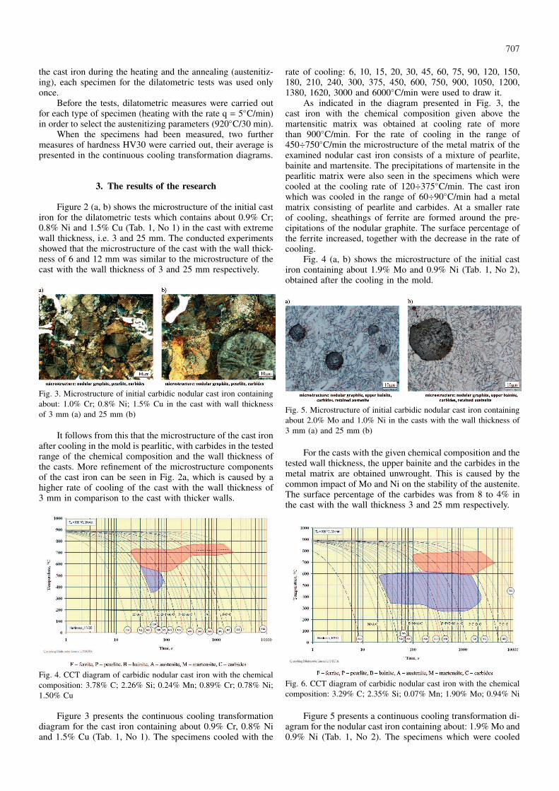
Figure 2 (a, b) shows the microstructure of the initial castiron for the dilatometric tests which contains about 0.9% Cr;0.8% Ni and 1.5% Cu (Tab. 1, No 1) in the cast with extremewall thickness, i.e. 3 and 25 mm. The conducted experimentsshowed that the microstructure of the cast with the wall thick-ness of 6 and 12 mm was similar to the microstructure of thecast with the wall thickness of 3 and 25 mm respectively.
Fig. 3. Microstructure of initial carbidic nodular cast iron containingabout: 1.0% Cr; 0.8% Ni; 1.5% Cu in the cast with wall thicknessof 3 mm (a) and 25 mm (b)
It follows from this that the microstructure of the cast ironafter cooling in the mold is pearlitic, with carbides in the testedrange of the chemical composition and the wall thickness ofthe casts. More refinement of the microstructure componentsof the cast iron can be seen in Fig. 2a, which is caused by ahigher rate of cooling of the cast with the wall thickness of3 mm in comparison to the cast with thicker walls.
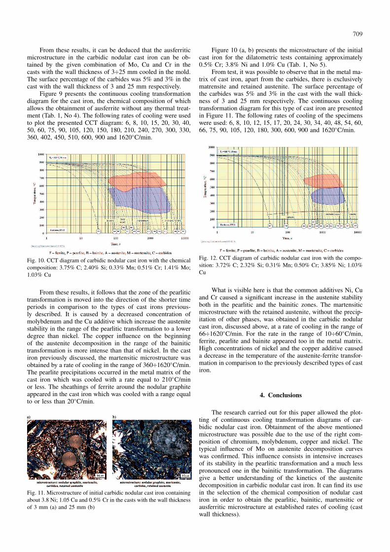
Fig. 4. CCT diagram of carbidic nodular cast iron with the chemicalcomposition: 3.78% C; 2.26% Si; 0.24% Mn; 0.89% Cr; 0.78% Ni;1.50% Cu
Figure 3 presents the continuous cooling transformationdiagram for the cast iron containing about 0.9% Cr, 0.8% Niand 1.5% Cu (Tab. 1, No 1). The specimens cooled with the
rate of cooling: 6, 10, 15, 20, 30, 45, 60, 75, 90, 120, 150,180, 210, 240, 300, 375, 450, 600, 750, 900, 1050, 1200,1380, 1620, 3000 and 6000◦C/min were used to draw it.
As indicated in the diagram presented in Fig. 3, thecast iron with the chemical composition given above themartensitic matrix was obtained at cooling rate of morethan 900◦C/min. For the rate of cooling in the range of450÷750◦C/min the microstructure of the metal matrix of theexamined nodular cast iron consists of a mixture of pearlite,bainite and martensite. The precipitations of martensite in thepearlitic matrix were also seen in the specimens which werecooled at the cooling rate of 120÷375◦C/min. The cast ironwhich was cooled in the range of 60÷90◦C/min had a metalmatrix consisting of pearlite and carbides. At a smaller rateof cooling, sheathings of ferrite are formed around the pre-cipitations of the nodular graphite. The surface percentage ofthe ferrite increased, together with the decrease in the rate ofcooling.
Fig. 4 (a, b) shows the microstructure of the initial castiron containing about 1.9% Mo and 0.9% Ni (Tab. 1, No 2),obtained after the cooling in the mold.
Fig. 5. Microstructure of initial carbidic nodular cast iron containingabout 2.0% Mo and 1.0% Ni in the casts with the wall thickness of3 mm (a) and 25 mm (b)
For the casts with the given chemical composition and thetested wall thickness, the upper bainite and the carbides in themetal matrix are obtained unwrought. This is caused by thecommon impact of Mo and Ni on the stability of the austenite.The surface percentage of the carbides was from 8 to 4% inthe cast with the wall thickness 3 and 25 mm respectively.
Fig. 6. CCT diagram of carbidic nodular cast iron with the chemicalcomposition: 3.29% C; 2.35% Si; 0.07% Mn; 1.90% Mo; 0.94% Ni
Figure 5 presents a continuous cooling transformation di-agram for the nodular cast iron containing about: 1.9% Mo and0.9% Ni (Tab. 1, No 2). The specimens which were cooled
708
with the rate of cooling: 3, 6, 8, 10, 15, 20, 24, 30, 45, 60,75, 90, 105, 120, 135, 150, 180, 240, 300, 375, 450, 600, 675,750, 900, 1050, 1200, 1620, 2100 and 6000◦C/min were usedto draw it.
From this diagram, it is clear that the molybdenum andnickel, with concentrations of about 1.9% and 0.9% respec-tively, caused the movement of the pearlitic transformationzone in the direction of longer periods of time in comparisonto the cast iron without Mo. The austenite stability in thebainitic range is similar to that in the cast iron without theMo additive. This indicates that molybdenum increases theaustenite stability essentially in the range of its transformationinto pearlite. However, it does not have much influence on itsstability in the bainitic transformation. At the same time, thiselement caused the expansion of the bainitic transformationrange in the direction of longer times (lower rates of cooling).The temperature at the beginning of the martensitic transfor-mation is higher in comparison to the previously describedkind of cast iron. It is caused by the lack of copper and alow concentration of manganese. The presence of the abovementioned elements causes a decrease in the temperature Ms.The presence of about 1.9% Mo did not have any influence onthe decrease in temperature of the beginning of the martensitictransformation because the majority of its atoms form part ofthe carbides. It is for this reason that its concentration in theaustenite is low [12].
The bainitic microstructure without the precipitations offerrite and pearlite was obtained in the cast iron being cooledat the rate of 105÷900◦C/min. Apart from the bainite the met-al matrix contained the carbides and the martensite whosesurface percentage decreased when the rate of cooling alsodecreased. At smaller rates of cooling, ferrite and pearlite ap-peared in the cast iron matrix. Martensite precipitations wereobserved for the specimens cooled at a rate no lower than30◦C/min. At the rate of cooling in the range of 10÷24◦C/minthe microstructure of the metal matrix consisted of a mixtureof the ferrite, pearlite and bainite. At lower rates of cooling,the ferrite and pearlite was observed in the tested nodular castiron.
Figure 6 (a, b) presents the microstructure of the initialcarbidic nodular cast iron containing about 2.0% Mo and 1.6%Ni.
Fig. 7. Microstructure of initial carbidic nodular cast iron containingabout 2.0% Mo and 1.6% Ni in the casts with wall thickness of 3mm (a) and 25 mm (b)
The increase in the nickel content with a similar contentof molybdenum caused the presence of upper and lower bai-nite and the carbides in the metal matrix of the initial castiron used for the dilatometric tests. In the casts with a wallthickness of 3 mm in the metal matrix, a small quantity ofmartensite additionally appeared. This is caused by a higherrate of cooling in comparison to the cast with a wall thicknessof 25 mm. The research showed that in order to eliminate the
martensite in the thin-wall casts, it is necessary to decreasethe content of nickel to about 1.3%. The surface percentageof the carbides was similar to the cast iron containing 1.9%Mo and 0.9% Ni.
Figure 7 presents the continuous cooling transformationdiagram of the cast iron containing about 2.0% Mo and 1.6%Ni (Tab. 1, No 3). The following rates of cooling were applied:6, 7, 8, 10, 12, 15, 20, 24, 30, 36, 45, 60, 75, 90, 105, 120,150, 180, 240, 300, 360, 396, 450, 510, 600, 750, 900 and1620◦C/min.
Fig. 8. CCT diagram of carbidic nodular cast iron with the chemicalcomposition: 3.83% C; 2.36% Si; 0.06% Mn; 2.00% Mo; 1.62% Ni
From CCT diagram presented in Figure 7 it is clear thatthe increase of the nickel content in 0.7% at a similar molyb-denum content caused the increase in the austenite stabilityin the range of transformation in pearlite and bainite. Thedecrease of the temperature of the γ ⇐⇒ α transformationwas caused by the pearlitogenic activity of the nickel. Withregard for the movement of the curve of the beginning ofthe austenite decomposition in the bainitic zone to the direc-tion of longer periods of time, the cast iron is characterizedby increased quenching. The temperature of the end of theγ → bainite transformation is lower in comparison to the castiron containing about 0.9% Ni. The bainitic-martensitic mi-crostructure in the cast iron in question was obtained by a rateof cooling in the range of 90÷750◦C/min.
The increase in the content of nickel also caused a de-crease in temperature Ms and thus, a decrease in the hardnessof the tested cast iron as a result of increased levels of retainedaustenite.
The microstructure of the initial cast iron for the dilato-metric tests, containing approximately 1.4% Mo; 0.5% Cr and1.0% Cu, is presented in Figure 8 (a, b).
Fig. 9. Microstructure of initial carbidic nodular cast iron containingabout: 1.5% Mo; 1.0% Cu and 0.5% Cr in the casts with the wallthickness of 3 mm (a) and 25 mm (b)
709
From these results, it can be deduced that the ausferriticmicrostructure in the carbidic nodular cast iron can be ob-tained by the given combination of Mo, Cu and Cr in thecasts with the wall thickness of 3÷25 mm cooled in the mold.The surface percentage of the carbides was 5% and 3% in thecast with the wall thickness of 3 and 25 mm respectively.
Figure 9 presents the continuous cooling transformationdiagram for the cast iron, the chemical composition of whichallows the obtainment of ausferrite without any thermal treat-ment (Tab. 1, No 4). The following rates of cooling were usedto plot the presented CCT diagram: 6, 8, 10, 15, 20, 30, 40,50, 60, 75, 90, 105, 120, 150, 180, 210, 240, 270, 300, 330,360, 402, 450, 510, 600, 900 and 1620◦C/min.
Fig. 10. CCT diagram of carbidic nodular cast iron with the chemicalcomposition: 3.75% C; 2.40% Si; 0.33% Mn; 0.51% Cr; 1.41% Mo;1.03% Cu
From these results, it follows that the zone of the pearlitictransformation is moved into the direction of the shorter timeperiods in comparison to the types of cast irons previous-ly described. It is caused by a decreased concentration ofmolybdenum and the Cu additive which increase the austenitestability in the range of the pearlitic transformation to a lowerdegree than nickel. The copper influence on the beginningof the austenite decomposition in the range of the bainitictransformation is more intense than that of nickel. In the castiron previously discussed, the martensitic microstructure wasobtained by a rate of cooling in the range of 360÷1620◦C/min.The pearlite precipitations occurred in the metal matrix of thecast iron which was cooled with a rate equal to 210◦C/minor less. The sheathings of ferrite around the nodular graphiteappeared in the cast iron which was cooled with a range equalto or less than 20◦C/min.
Fig. 11. Microstructure of initial carbidic nodular cast iron containingabout 3.8 Ni; 1.05 Cu and 0.5% Cr in the casts with the wall thicknessof 3 mm (a) and 25 mm (b)
Figure 10 (a, b) presents the microstructure of the initialcast iron for the dilatometric tests containing approximately0.5% Cr; 3.8% Ni and 1.0% Cu (Tab. 1, No 5).
From test, it was possible to observe that in the metal ma-trix of cast iron, apart from the carbides, there is exclusivelymatrensite and retained austenite. The surface percentage ofthe carbides was 5% and 3% in the cast with the wall thick-ness of 3 and 25 mm respectively. The continuous coolingtransformation diagram for this type of cast iron are presentedin Figure 11. The following rates of cooling of the specimenswere used: 6, 8, 10, 12, 15, 17, 20, 24, 30, 34, 40, 48, 54, 60,66, 75, 90, 105, 120, 180, 300, 600, 900 and 1620◦C/min.
Fig. 12. CCT diagram of carbidic nodular cast iron with the compo-sition: 3.72% C; 2.32% Si; 0.31% Mn; 0.50% Cr; 3.85% Ni; 1.03%Cu
What is visible here is that the common additives Ni, Cuand Cr caused a significant increase in the austenite stabilityboth in the pearlitic and the bainitic zones. The martensiticmicrostructure with the retained austenite, without the precip-itation of other phases, was obtained in the carbidic nodularcast iron, discussed above, at a rate of cooling in the range of66÷1620◦C/min. For the rate in the range of 10÷60◦C/min,ferrite, pearlite and bainite appeared too in the metal matrix.High concentrations of nickel and the copper additive causeda decrease in the temperature of the austenite-ferrite transfor-mation in comparison to the previously described types of castiron.
4. Conclusions
The research carried out for this paper allowed the plot-ting of continuous cooling transformation diagrams of car-bidic nodular cast iron. Obtainment of the above mentionedmicrostructure was possible due to the use of the right com-position of chromium, molybdenum, copper and nickel. Thetypical influence of Mo on austenite decomposition curveswas confirmed. This influence consists in intensive increasesof its stability in the pearlitic transformation and a much lesspronounced one in the bainitic transformation. The diagramsgive a better understanding of the kinetics of the austenitedecomposition in carbidic nodular cast iron. It can find its usein the selection of the chemical composition of nodular castiron in order to obtain the pearlitic, bainitic, martensitic orausferritic microstructure at established rates of cooling (castwall thickness).
710
REFERENCES
[1] E. Guzik, The Processes of Cast Iron Refining, Archives ofFoundry Engineering, 2001, Monography No 1M [in Polish].
[2] E. Guzik, W. Kapturkiewicz, J. Lelito, Principles of Obtainingof the Ausferritic Cast Iron. International Science Conference,on the topic of ADI – foundry offer for the designers and castsusers. Krakow, 23-24.IX.2000, p. I/11 [in Polish].
[3] E. Guzik, Ausferritic Cast Iron and Its Kinds, Productive Sys-tems Optimization Tendencies in Foundries, Team work un-der the editorship of Stanisław Pietrowski, Katowice – Gliwice2010, pp. 105-110 [in Polish].
[4] S. Pietrowski, Nodular Cast Iron with the Structure of BainiticFerrite with Austenite or Bainitic, Material Science Archives4, 18, 253-273 (1997) [in Polish].
[5] G. Gumienny, Bainitic Nodular Cast Iron with Carbides Ob-taining with Use of Inmold Method, Archives of Foundry En-gineering 9, 3, 243-248 (2009).
[6] G. Gumienny, Bainitic-martensitic Nodular Cast Iron with Car-bides, Archives of Foundry Engineering 10, 2, 63-68 (2010).
[7] S. Pietrowski, G. Gumienny, Crystallization of Nodular CastIron with Carbides, Archives of Foundry Engineering 8, 4,236-240 (2008).
[8] S. Pietrowski, G. Gumienny, Carbides in Nodular Cast Ironwith Cr and Mo, Archives of Foundry Engineering 7, 3, 223(2007).
[9] M. Ferry, W. Xu, Microstructural and Crystallographic Featuresof Ausferrite in As-cast Gray Iron, Materials Characterization53, 43-49 (2004).
[10] I. Olejarczyk-Wożeńska, A. Adrian, H. Adrian, B. Mrzygłód,Parametric Representation of TTT Diagrams of ADI Cast Iron,Archives of Metallurgy and Materials 57, 2, 613-617 (2012).
[11] Z. Górny, S. Kluska-Nawarecka, D. Wilk-Kołodziejczyk,Heuristic Models of the Toughening Process to improvethe Properties of Non-Ferrous Metal Alloys. Archives ofMetallurgy and Materials 58, 3, 849-852 (2013) DOI:10.2478/amm-2013-0085.
[12] S. Pietrowski, G. Gumienny, Microsegregation in Nodular CastIron with Carbides, Archives of Foundry Engineering 12, 4,127-134 (2012).


![eAID ICSSCCET.2016.106 Production of Carbidic Austempered ...edlib.net/2016/icssccet/ICSSCCET2016106.pdf · “ Production of Carbidic Austempered Ductile Iron [CADI] ”. International](https://static.documents.pub/doc/80x56/5aba8d0d7f8b9a24028b9b30/eaid-icssccet2016106-production-of-carbidic-austempered-edlibnet2016icssccet.jpg)


