24
The Compaction People Continuous Dry Granulation by Roller Compaction An Introduction to the Alexanderwerk Roller Compaction Process By Marcus Becker-Hardt 05.07.2018
The Compaction People
Continuous Dry Granulation by Roller Compaction
An Introduction to the Alexanderwerk Roller Compaction Process
By Marcus Becker-Hardt
05.07.2018

Continuous Dry Granulation by Roller Compaction
2
Content 1 Background on Continuous Dry Granulation by Roller Compaction ............................................... 3
1.1 Introduction ............................................................................................................................. 3
1.2 From Raw Material Powder to Flake ....................................................................................... 4
1.2.1 Feed Hopper .................................................................................................................... 4
1.2.2 Feed Screw with Vacuum Unit ........................................................................................ 5
1.2.3 Rollers .............................................................................................................................. 7
Bonding mechanism .................................................................................................... 7
The key parameters: Compaction Force and Roller-Gap ............................................ 7
Dragging the material in. The right Roller Surface ...................................................... 8
Side Sealings and Separation of Side Seal Losses ...................................................... 10
1.3 From Flake to Granulate ........................................................................................................ 11
1.3.1 Flake Crusher, Pre- and Fine-Granulator ....................................................................... 11
Granulator Speed and Mesh size .............................................................................. 11
2 Demonstration .............................................................................................................................. 14
2.1 Materials and Methods ......................................................................................................... 14
2.1.1 Experimental Setup ....................................................................................................... 14
2.1.2 Experiments ................................................................................................................... 15
2.1.3 Analysis by Alexanderwerk ............................................................................................ 15
Screening analysis ..................................................................................................... 15
Throughput measurement ........................................................................................ 15
2.1.4 Analysis by Shin-Etsu ..................................................................................................... 15
2.1.5 Chemicals used .............................................................................................................. 15
2.2 Comparative Formulation with PVA ...................................................................................... 16
2.2.1 Results on the Powder and impact of the compaction variables .................................. 16
2.2.2 Evaluation of the Tablets from the Comparative Formulation ..................................... 17
2.3 Additional Work .................................................................................................................... 18
3 Summary ....................................................................................................................................... 21
4 References ..................................................................................................................................... 22
5 Appendix ........................................................................................................................................ 23

Continuous Dry Granulation by Roller Compaction
3
1 Background on Continuous Dry Granulation by Roller Compaction
1.1 Introduction
Continuous dry granulation by roller compaction is a well-established process in pharmaceutical, chemical and life science industry. In pharmaceutical applications the most common target is to increase the flowability of a powder or powder blend to enable the fast and homogeneous filling of a tablet press. The challenge is to produce tablets of constant weight and sufficient strength, while maintaining an even distribution of the Active Pharmaceutical Ingredients (API). This can be achieved by roller compaction for a wide range of products and without the need of additional ingredients such as binders, moisture or lubricants. Furthermore, dry granulation by roller compaction is used to eliminate dust, increase the bulk density, reduce the storage volume, improve handling and manipulate the dissolution properties.
Dry granulation by roller compaction consists of two separate steps. The first step is an agglomeration step, starting From Raw Material Powder to Flake (1.2). The flake (also referred to as ribbon) is a tablet like band that comes out of the roller compactor. The poor flowing raw material powder is conveyed from the Feed Hopper (1.2.1) by using a Feed Screw with Vacuum Unit (1.2.2) to bring it to the Rollers (1.2.3), where it is compressed into a flake. The second step is a size reduction step, From Flake to Granulate (1.3). Here the flake is milled and reduced to a well flowing granulate by using a Flake Crusher, Pre- and Fine-Granulator (1.3.1). A Detailed view on a Roller Compactor can be seen in Figure 1 and the flow diagram can be seen in Figure 2. To ensure a good granulate quality the quality of the flake as an intermediate product is a key factor. The flake quality is determined by The key parameters: Compaction Force and Roller-Gap (1.2.3.2) as well as by the feed of the raw material to the rollers. For feeding, it is important to have an even distribution of the material along the roller width to guarantee an even application of the compaction force to the powder along the roller width. Yet due to the milling there will always be a small quantity of fine material produced in the granulation. Therefore, the granulation of the flake is done in three steps, to avoid excessive amounts of energy being put into the product when it is milled down from a large flake into small granulates. If the milling were done in one step, this would lead to the production of more fine material. Therefore, the granulation is done by a Flake Crusher, Pre- and Fine-Granulator (1.3.1). The most important variables for the granulation are the Granulator Speed and Mesh size (1.3.1.1). The remaining fines can either be kept in the granulate and compressed in the tablet press or it can be screened off and recycled into the raw material feed.
Figure 1:Detailed view on a Roller Compactor
Figure 2: Flow Diagram of a Roller Compactor

Continuous Dry Granulation by Roller Compaction
4
1.2 From Raw Material Powder to Flake In order to form a stable flake, the powdery raw material must be fed from the raw material hopper to the rollers. The mechanics of how this is done is given by the orientation of the rollers which can be horizontally, vertically or inclined. Horizontally or inclined rollers can be fed by gravity. However, since gravity is constant and usually poor flowing powders are roller compacted this will lead to a poor process control and a high amount of uncompacted material falling through the roller gap especially during start up and shut down but also during the regular operation. This effect can be minimized by the use of a feed screw, but in horizontally or inclined rollers, gravity will always be a constant that makes it hard to control the uncompacted material. Furthermore, leakages will always fall into the same direction as the flake which makes it difficult to separate the leakages from the produced flakes. When the rollers are vertically oriented, the feeding of the material to the rollers can be controlled precisely by a feed screw which decreases the amount of losses during start up and shut down. In addition, the uncompacted powder that escapes can be separated (see tube in Figure 1 on the lower left side) from the flake and can be collected and recycled.
Figure 3: From left to right, raw material, flake, granulate of paracetamol blend with Lactose, Cellulose and PVA.
1.2.1 Feed Hopper The optimal way of bringing the powder between the rollers is of major importance for the flake quality. Because the material gets compacted, which essentialy means that the air is pushed out of the product, it is nessecary to provide a path for the air to escape from the product. Therefore the raw material powder should not be pre-compacted in the feed screw, since this would decrease the permeability of the powder and block the way back through the feed screw for the air. When the feed screw is conveying the raw material without pre-compacting it, the air can go back through the screw and come out of the hopper or through a second, so called Combi-Vent Feeder® (CVF) chamber (see blue arrows in Figure 4). The CVF can also be used for recycle and mixing of material into the process

Continuous Dry Granulation by Roller Compaction
5
(see 1.2.3.4 Side Sealings and Separation). The material falling into the second CVF chamber (marked red) will be conveyed immediatly and than be mixed with the raw material in the first chamber (marked grey) by the feed screw. This enables the production of a constant and homogeneous flake quality. On small scale equipment like the WP 120 Pharma the feeding hopper is relativly small, which would lead to solid bridging and rat holing in the hopper if space would be occupied by the second CVF camber. In this case the Advanced-Feeding-System (AFS), which is a small pipe at the rear end of the feed screw can be used to deaerate. This is especially needed if the machine is used in an isolator for high containment solutions or if the raw material is fed automaticly by e.g. a level sensor contolled rotary valve or from an inert container into the feed hopper or an otherwise closed system. However, due to the small size of the hopper the raw material layer in the hopper is small and permeable enough for many products to let the material deareate through the feed hopper, if the machine is hand filled.
Figure 4: Schematic view on the feeding and compaction zone when a Combi-Vent-Feeder® is installed.
Due to the purpose of the Roller Compactor the raw materials that are processed usually are poor flowing or even sticking. Therefore, the formation of solid bridges or rat holes in the feed hopper can’t always be avoided and are a known issue. Therefore, a stirrer is installed in the hopper of all roller compactors. If this is not sufficient, solid bridges and rat holes can be destroyed by the use of a knocker or vibrator that is attached to the feed hopper and works in intervals which are adjustable by timers.
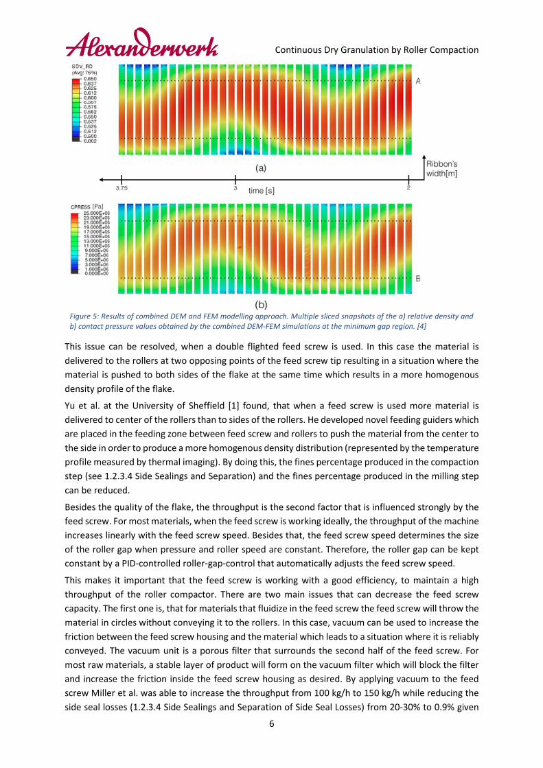
1.2.2 Feed Screw with Vacuum Unit The quality of the final granulate is directly related to the quality of the flake. In most cases a flake with a higher tensile strength will lead to a granulate with less fines [1]. The tensile strength can be correlated to the porosity of a given material [2] [3]. This makes it important that a flake is produced with a homogenous density profile along the flake width and length. When a feed screw is used with a single flight this will lead to a condition, where the material is always pushed out at one point of the feed screw. This will then lead to more product between the rollers, more compaction force applied and subsequently a higher flake density at this point. This will result in an uneven flake density that fluctuates depending on the feed screw rotation. The density profile was modeled by Mazor et al. using a combined DEM and FEM approach [4]. In Figure 5 a part of their results can be seen. This observation can be confirmed by the experience of Alexanderwerk.
Continuous Dry Granulation by Roller Compaction
6
Figure 5: Results of combined DEM and FEM modelling approach. Multiple sliced snapshots of the a) relative density and b) contact pressure values obtained by the combined DEM-FEM simulations at the minimum gap region. [4]
This issue can be resolved, when a double flighted feed screw is used. In this case the material is delivered to the rollers at two opposing points of the feed screw tip resulting in a situation where the material is pushed to both sides of the flake at the same time which results in a more homogenous density profile of the flake.
Yu et al. at the University of Sheffield [1] found, that when a feed screw is used more material is delivered to center of the rollers than to sides of the rollers. He developed novel feeding guiders which are placed in the feeding zone between feed screw and rollers to push the material from the center to the side in order to produce a more homogenous density distribution (represented by the temperature profile measured by thermal imaging). By doing this, the fines percentage produced in the compaction step (see 1.2.3.4 Side Sealings and Separation) and the fines percentage produced in the milling step can be reduced.
Besides the quality of the flake, the throughput is the second factor that is influenced strongly by the feed screw. For most materials, when the feed screw is working ideally, the throughput of the machine increases linearly with the feed screw speed. Besides that, the feed screw speed determines the size of the roller gap when pressure and roller speed are constant. Therefore, the roller gap can be kept constant by a PID-controlled roller-gap-control that automatically adjusts the feed screw speed.
This makes it important that the feed screw is working with a good efficiency, to maintain a high throughput of the roller compactor. There are two main issues that can decrease the feed screw capacity. The first one is, that for materials that fluidize in the feed screw the feed screw will throw the material in circles without conveying it to the rollers. In this case, vacuum can be used to increase the friction between the feed screw housing and the material which leads to a situation where it is reliably conveyed. The vacuum unit is a porous filter that surrounds the second half of the feed screw. For most raw materials, a stable layer of product will form on the vacuum filter which will block the filter and increase the friction inside the feed screw housing as desired. By applying vacuum to the feed screw Miller et al. was able to increase the throughput from 100 kg/h to 150 kg/h while reducing the side seal losses (1.2.3.4 Side Sealings and Separation of Side Seal Losses) from 20-30% to 0.9% given
Continuous Dry Granulation by Roller Compaction
7
otherwise constant settings [5]. If the layer becomes too hard and starts to block the feed screw the vacuum pressure can either be reduced or a blow back system can be installed to clean off the filter from time to time. However, especially for very fine and low bulk density materials with a high grain hardness the product layer will still be permeable and can in some cases be used to deaerate the material in addition to the CVF. The second issue that can reduce the feed screw efficiency is material can stick to the feed screw. In this case a plastic (PEEK) feed screw can be used to avoid or reduce the sticking of the material on the feed screw and keep the process running.
1.2.3 Rollers Bonding mechanism
Similar to tablet presses, roller compaction uses interparticulate bond formation. The bond formation can be characterized by the following steps which happen in this order [6]:
1. Particle rearrangement: occurs initially as powder movement begins filling void spaces. Air begins to move closer together, thereby increasing the powder blend’s density. Particle shape and size are key factors in the rearrangement process. Spherical particles will move less than other-shaped particles because of their close initial packing.
2. Particle deformation: occurs as compressional forces are increased. This deformation increases the points of contact between particles where bonding occurs and is described as plastic deformation.
3. Particle fragmentation: is the next stage of bonding formation. It happens at higher compressional force levels. Here, particle fracturing creates multiple new surface sites, additional contact points, and potential bonding sites.
4. Particle bonding: occurs when plastic deformation and fragmentation happen. It is generally accepted that bonding happens at the molecular level and is due to van der Waals forces.
The similarity of the bonding mechanisms in the tablet press and roller compaction are an advantage and disadvantage at the same time. The disadvantage is, that in some cases it can happen, that the tablets produced from roller compactor granulate can be weaker than tablets produced from the initial powder because the surfaces needed for the bonding are already occupied. In this case it can be found, that the tablets become weaker as more compaction force was applied in the roller compactor [7]. Yet in other cases it was found that the roller compaction does not have an impact on the tableting process, or even improves the tablet strength and can be used to affect the release time [7] or produce a smoother tablet surface [8]. Also, for most materials e.g. calcium carbonate, a certain degree of fine material is needed to reach a sufficient tablet hardness [9]. The advantage is, that due to the similar bonding mechanism no additional process steps, binders, or moisture is needed to be added before and removed after the roller compaction to produce a granulate suitable for the tablet press. Therefore, additional mixing and drying equipment to add and remove water or solvents can be avoided and no thermal stress is applied to the product. This makes continuous dry granulation by roller compaction suitable for heat and moisture sensitive products.
The key parameters: Compaction Force and Roller-Gap The compaction force and roller gap are the most dominant process parameters, in this order. The roller speed can also have an impact but is usually not dominant compared to Compaction Force and Gap. As a measure of the flake quality, different material properties can be used. Some of the more common ones are the porosity, density or relative density but also the tensile strength of the flake. In some cases, the flake temperature as it comes out of the roller gap is measured. However, since the temperature is a property that depends on many boundary conditions such as e.g. the inlet temperature, if and to which extent the roller cooling was used, the flake temperature can only be used as a measure for the homogeneity of flake [10].

Continuous Dry Granulation by Roller Compaction
8
How much each parameter is affecting the flake quality is strongly depending on the raw material characteristics. Yet for the vast majority of products the compaction force is the dominant parameter. Followed by the roller gap (also called separation) and the roller speed. In Figure 6 the impact of compaction force (roller force) and roller separation on the relative density (solid contours) and the throughput (dashed contours) on an arbitrary material is presented. The values are derived from a model that was developed by AstraZeneca [11]. It can be seen, that the relative density increases strongly with roller force and decreases slightly with the roller separation (roller gap). Even though it can be seen, that for this arbitrary material the impact of the roller gap increases when higher roller forces are applied. However, it can also be seen, that the throughput can be increased by increasing the roller gap, this correlation is linear in most cases and can be linked to the feed screw speed. But to compensate the effect of the higher roller gap the compaction force needs to be increased to compensate for the loss in relative density. The impact of the roller speed is similar to the impact of the roller gap and will not be discussed further.
Even though the flake density rises when the compaction force is increased, this effect has its limits. Usually the flake density rises linear with the pressure (for low and medium pressure) and starts to level off for higher pressures. The latter also reflects in the bulk density of the final granulate (see Figure 7). Here it can also be seen, that the slope as well as the maximum bulk density differ strongly and depend on the raw material that was used.
Figure 6: The influence of roller force and roller separation (gap) on ribbon relative density (solid contours) and mass throughput in g/min (dashed contours). Mass throughput corresponds to a roll speed of 10 rpm. Plot generated using arbitrary material and roller geometric in a compaction processing model developed by AstraZeneca. [11]
Figure 7: Influence of pressure on bulk density for different products produced on different Alexanderwerk roller compactors.
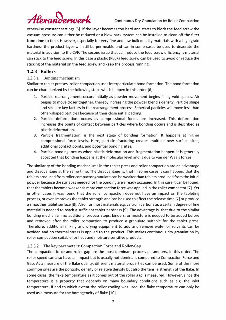
Dragging the material in. The right Roller Surface To avoid pre-compaction in the feed screw (see 1.2.1 Feed Hopper) the design of the roller surface is a leading factor. The idea is to create a situation in which the material is drawn into the gap between the rollers (roller gap) by the rollers themselves. When the material is fed towards the rollers they enter the region that is called the slip area, marked blue, green and yellow in Figure 8. In this area the friction between the rollers and the powder will accelerate the powder until it reaches the same velocity as the roller. The area of zero velocity difference between powder and roller is the so-called nip-area, marked red in Figure 8. After the powder has entered the nip area the density of the powder increases rapidly, which can be seen in Figure 9 (green, yellow and red). This area is where the powder is converted into the flake.
0,0
0,2
0,4
0,6
0,8
0,0
0,1
0,2
0,3
0,4
0 3 6 9 12 15BD
(g/c
c La
ctos
e)
BD (g
/cc
Poly
carb
onat
and
Sili
ca)
Roller Force (kN/cm)
Polycarbonat WP 200 PharmaSilica WP 50N/75Lactose WP 120 Pharma
Continuous Dry Granulation by Roller Compaction
9
Figure 8: Isometric view on the 3-D FEM modeled material VELOCITY distribution in the WP 120 Pharma developed at the University of Purdue [12]
Figure 9: Isometric view on the 3-D FEM modeled material DENSITY distribution in the WP 120 Pharma developed at the University of Purdue [12]
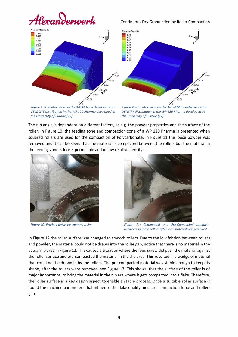
The nip angle is dependent on different factors, as e.g. the powder properties and the surface of the roller. In Figure 10, the feeding zone and compaction zone of a WP 120 Pharma is presented when squared rollers are used for the compaction of Polycarbonate. In Figure 11 the loose powder was removed and it can be seen, that the material is compacted between the rollers but the material in the feeding zone is loose, permeable and of low relative density.
Figure 10: Product between squared roller
Figure 11: Compacted and Pre-Compacted product between squared rollers after loos material was removed.
In Figure 12 the roller surface was changed to smooth rollers. Due to the low friction between rollers and powder, the material could not be drawn into the roller gap, notice that there is no material in the actual nip area in Figure 12. This caused a situation where the feed screw did push the material against the roller surface and pre-compacted the material in the slip area. This resulted in a wedge of material that could not be drawn in by the rollers. The pre-compacted material was stable enough to keep its shape, after the rollers were removed, see Figure 13. This shows, that the surface of the roller is of major importance, to bring the material in the nip are where it gets compacted into a flake. Therefore, the roller surface is a key design aspect to enable a stable process. Once a suitable roller surface is found the machine parameters that influence the flake quality most are compaction force and roller-gap.

Continuous Dry Granulation by Roller Compaction
10
Figure 12: Product being stuck in the slip area when smooth rollers are used.
Figure 13: Pre-Compacted material from the smooth rollers after the rollers and loose material was removed.
Side Sealings and Separation of Side Seal Losses As mentioned earlier, side seal losses will occur on roller compactors. Side seal losses are uncompacted material, that falls off at the sides of the rollers. When the rollers are oriented vertically, they can be separated from the flakes via a separation chute by gravity, see Figure 1 and Figure 2 in chapter 1.1. These losses can be minimized by using the vacuum system on the feed screw [5], using the novel guiders developed by Yu et al. [1] and/ or by using the adequate side sealing system on the rollers. There are two approaches for the side seals. The first option are static side seals, which are plastic plates that are mounted at the side of the roller gap, see Figure 14. This option will lead to a situation, where more material is pushed to the center than to the sides of the rollers [1] (see arrows in Figure 14). This subsequently leads to more pressure being applied to the product at the center than at the sides of the rollers. Depending on the product, this can lead to weak edges of the flake. As an alternative, circumferential side seals can be used. This means that rims are mounted to the lower roller and the upper roller is running in between these rims (see Figure 15). Since the rim will drag some of the material into the roller gap, more material is at the sides of the rollers (see arrows in Figure 15). At high pressure this can lead to over compression and material sticking in the edges of the circumferential side seals. For the static side seals this cannot happen, since small amounts of product can still fall off at the sides off the rollers, which will prevent over-compression at the sides of the rollers.
Figure 14: Schematic view on static side seals, the arrows indicate how the material is dragged in.
Figure 15: Schematic view on circumferential side seals, the arrows indicate how the material is dragged in.
Continuous Dry Granulation by Roller Compaction
11
1.3 From Flake to Granulate
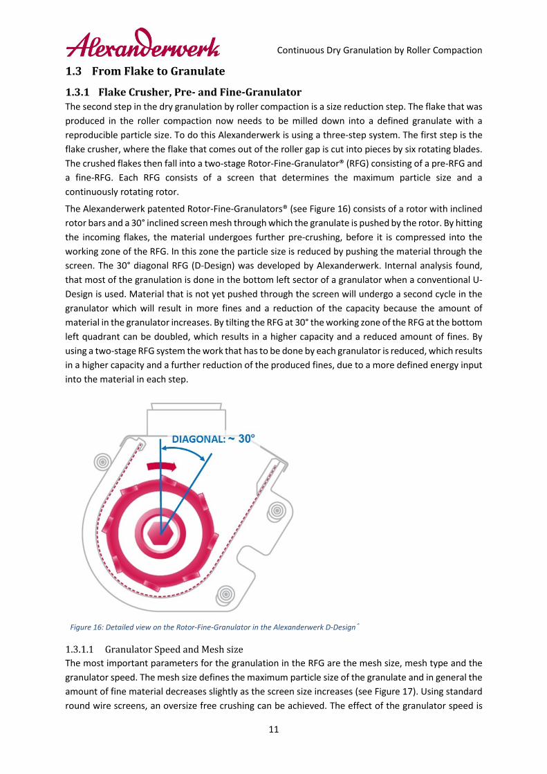
1.3.1 Flake Crusher, Pre- and Fine-Granulator The second step in the dry granulation by roller compaction is a size reduction step. The flake that was produced in the roller compaction now needs to be milled down into a defined granulate with a reproducible particle size. To do this Alexanderwerk is using a three-step system. The first step is the flake crusher, where the flake that comes out of the roller gap is cut into pieces by six rotating blades. The crushed flakes then fall into a two-stage Rotor-Fine-Granulator® (RFG) consisting of a pre-RFG and a fine-RFG. Each RFG consists of a screen that determines the maximum particle size and a continuously rotating rotor.
The Alexanderwerk patented Rotor-Fine-Granulators® (see Figure 16) consists of a rotor with inclined rotor bars and a 30° inclined screen mesh through which the granulate is pushed by the rotor. By hitting the incoming flakes, the material undergoes further pre-crushing, before it is compressed into the working zone of the RFG. In this zone the particle size is reduced by pushing the material through the screen. The 30° diagonal RFG (D-Design) was developed by Alexanderwerk. Internal analysis found, that most of the granulation is done in the bottom left sector of a granulator when a conventional U-Design is used. Material that is not yet pushed through the screen will undergo a second cycle in the granulator which will result in more fines and a reduction of the capacity because the amount of material in the granulator increases. By tilting the RFG at 30° the working zone of the RFG at the bottom left quadrant can be doubled, which results in a higher capacity and a reduced amount of fines. By using a two-stage RFG system the work that has to be done by each granulator is reduced, which results in a higher capacity and a further reduction of the produced fines, due to a more defined energy input into the material in each step.
Figure 16: Detailed view on the Rotor-Fine-Granulator in the Alexanderwerk D-Design®
Granulator Speed and Mesh size The most important parameters for the granulation in the RFG are the mesh size, mesh type and the granulator speed. The mesh size defines the maximum particle size of the granulate and in general the amount of fine material decreases slightly as the screen size increases (see Figure 17). Using standard round wire screens, an oversize free crushing can be achieved. The effect of the granulator speed is

Continuous Dry Granulation by Roller Compaction
12
less intuitive than the effect of the mesh size. When a stable flake is granulated, a higher granulator-speed will lead to a reduction of the amount of fine material produced in the granulator (see Figure 17). Only when the flake is very porous and soft the number of fines will increase as the granulator speed increases.
Figure 17: Influence of RFG speed and screen size on a Paracetamol blend (CF) produced on the WP 120 Pharma.
An additional factor for the granulation is the gap between the rotor and the screen. This position can be adjusted and should be as close as possible without making metal to metal contact. A large gap can result in a reduction of the throughput due to blockages of the screen or the number of fines can increase as the material is not being pushed through the screen in one granulation cycle. To avoid a gap between the granulator and the screen, it can either be adjusted manually or the newly developed Automatic Granulation System (AGS) can be used to auto adjust the gap.
Regarding the quality of the flake it can be said that for most cases a hard flake with a high tensile strength will lead to less fines but also will decrease the lifetime of the screens that are used in the granulator. For very hard materials it is therefore better to change to different screen types such as square wire mesh or conidur screens, which have a longer life time, but also can lead to slight increases in the fines produced, which eventually also increases the bulk density. The tendency, that materials with a higher flake (ribbon) tensile strength produce less fines, was also indicated by Yu et al. [1] (see Figure 18), where fines are defined as material that is smaller than the d90 of the initial raw material powder and the flakes (ribbons) were produced with (TB-3) and without (original) the novel feeding guiders developed by Yu et al.
0%
10%
20%
30%
40%
50%
60%
70%
80%
90%
100%
0 0,2 0,4 0,6 0,8 1
Perc
enta
ge P
ass [
%]
Mesh Size [mm]
Accumulated Sum Curve
1.0 mm Screen, 108 RPM0.8 mm Screen, 108 RPM0.8 mm Screen, 50 RPM

Continuous Dry Granulation by Roller Compaction
13
Figure 18: Effect of ribbon tensile strength on fines percentage from crushing stage. The red dots represent samples that are produced using the original guiders. The black dots are from samples produced using the novel-feeding-guider TB-3 for microcrystalline cellulose MCC PH 101, Maltodextrin 6, Light sodium carbonate and Pharmatose 200 M.

Continuous Dry Granulation by Roller Compaction
14
2 Demonstration The demonstration of the Alexanderwerk Dry Granulation by Roller Compaction is part of a seminar, in which different granulation technologies are presented and compared on a tablet press. The objective is to obtain comparative results of these technologies. This paper focuses only on the granulates produced on the Alexanderwerk Roller Compaction and Dry Granulation technology and how they behave on the tablet press.
2.1 Materials and Methods
2.1.1 Experimental Setup The trials are carried out on an Alexanderwerk WP 120 Pharma (serial no.: 900-1080) roller compactor, located in the technical lab at the Alexanderwerk headquarter in Remscheid Germany. The machine is equipped with a feed hopper (with vibrator), single to double flighted stainless-steel feed screw, a 10 μm sintered metal vacuum filter, knurled 25 mm rollers, static side seals and a two stage RFG with Automatic Granulation System (AGS). The RFG is equipped with a 1.6 mm, 2.0 mm or a 3.15 mm round wire screen mesh in the pre-granulator and a 0.6 mm, 0.8 mm, 1 mm or 1.6 mm round wire screen mesh in the fine granulator. When the screen size is 1.0 mm or smaller a screen support is used. Side seal leakages are kept in the granulate or are discharged via the separation chute. The process flow diagram is shown in Figure 19 and a picture of the used machine is presented in Figure 20.
Figure 19: Process Flow Diagram. Figure 20: WP 120 Pharma (serial no.: 900-1080) as used.

Continuous Dry Granulation by Roller Compaction
15
2.1.2 Experiments - The raw material is fed in to the hopper by hand. - The machine is set up to the desired process parameters. - As soon as the process runs stable a sample of final granulates is taken for screening analysis. - The produced granulate gets collected and samples are send to Shin Etsu for further analysis
and to Romaco Kilian for tableting.
2.1.3 Analysis by Alexanderwerk Screening analysis
Screening analysis is carried out on a Haver & Böcker screening-analysis-machine. For the analysis, a sample of the granulates is screened using the following screens: 1 mm, 0.8 mm, 0.63 mm, 0.4 mm and 0.2 mm. The time is set to 7 minutes, the interval to 7 seconds and the amplitude to 0.5 mm. The D50 is calculated by linear interpolation.
Throughput measurement For the throughput measurement, all granulates are collected in a drum for 6 minutes and the collected sample is weighted.
2.1.4 Analysis by Shin-Etsu Granulate shape is analyzed using a JEOL JSM-IT100 scanning electron microscope in LV mode. Granulates are characterized for their particle size using a Retsch Camsizer XT. Tablet compression is performed after blending of granulate with magnesium stearate on a Romaco Kilian STYL’ONE Evolution (650 mg, EU-D 12 mm R18), simulating a KTP420X production press, at different compaction forces (10-40 kN). Tablet hardness, tablet friability, and tablet dissolution are tested on an Erweka TBH225, Erweka TA120, and Erweka DT720 dissolution tester equipped with UV analysis (n=6, USP apparatus 2, 50 rpm, 0.1 N HCl, pH=1.2, 900 mL, 37 °C, λ = 280 nm).
2.1.5 Chemicals used The powders that are tested are provided by Shin-Etsu. The first tests are carried out using a comparative formulation (CF). The CF is a mixture of paracetamol (the API), L-HPC LH-21 (low-substituted hydroxypropyl cellulose, a binder and disintegrant), lactose, and PVA JVP PE05-JPS as binder. This formulation is also used in the other granulation technologies for comparative results. Because the CF was not designed for Roller Compaction, in additional trials the formulation is adjusted to be more suitable for roller compaction. Three additional roller compaction specific formulations (AW-AF1, AW-AF2 and AW-AF3), where L-HPC LH-31 (micronized) and LH-21 and Metolose® SM-4 and PVA are varied, are tested (Table 1). Table 1: Recipe for the paracetamol blend (*magnesium stearate was not mixed into the blend for the roller compaction)
Formulation: Comparative (CF)
w/w [%] Additional 1 (AW-
AF1) w/w [%] Additional 2 (AW-
AF2) w/w [%] Additional 3 (AW-
AF3) w/w [%]
Paracetamol 20 20 20 20
L-HPC LH-21 12.5 - - 12.5
L-HPC LH-31 - 12.5 12.5 -
Lactose 64 64 64 64
PVA JVP PE05-JPS 3 3 - -
METOLOSE® SM-4 - - 3 3
Magnesium stearate* 0.5 0.5 0.5 0.5

Continuous Dry Granulation by Roller Compaction
16
Magnesium stearate is added after the roller compaction granulation and just before tableting by Romaco Kilian.
2.2 Comparative Formulation with PVA
2.2.1 Results on the Powder and impact of the compaction variables The first ten trials were carried out with the comparative formulation to find the best parameters for dry granulation by roller compaction and to demonstrate the effect of the different process variables on the granulate quality. For tableting tests granulates from trial A-8, which was produced at medium-high pressure (85 bar), a large granulator screen (1.6 mm) and a high granulator speed (100 RPM), was selected because it had a low angle of repose (AOR) and only few fines. The settings and results are presented in Table 2 and in greater detail in Table 4 in the Appendix. Table 2: Granulate Analysis provided of CF provided by Shin-Etsu (LOD is the Loss on Drying, Particle size analysis on the Camsizer XT, xc,min shown)
Trial Parameter [Force / Fine-RFG]
Bulk Density [g/cm³]
AOR [°]
LOD [%]
Q10 [mm]
Q50 [mm]
Q90 [mm]
A-4 70 bar / 0.6 mm 0.598 46.8 1.21 0.009 0.037 0.132 A-5 40 bar / 0.6 mm 0.584 50.5 1.08 0.008 0.035 0.136 A-7 85 bar / 0.6 mm 0.600 47.3 1.19 0.009 0.038 0.234 A-8 85 bar / 1.6 mm 0.661 47.1 1.03 0.011 0.065 1.103 A-9 100 bar / 1.6 mm 0.676 48.3 1.00 0.012 0.080 1.120 A-10 100 bar / 1.0 mm 0.661 44.8 1.05 0.011 0.060 0.524
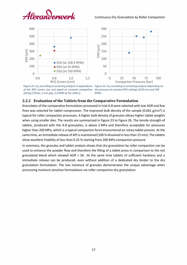
In trial A-1 to A-4 the effect of the RFG settings (speed and mesh size) on the granulate were tested at constant compaction settings. In trial A-5 to A-7 the effect of the pressure on the granulates were tested at constant RFG settings. The impact of the RFG settings on the D50 (according to screening analysis) can be seen in Figure 21 on the next page. The D50 increases as the screen size increases and decreases as the RFG speed increases. Both trends are typical for the RFG. The impact of the compaction pressure on the D50 can be seen in Figure 22. It can be seen that the particle size rises considerably from 40 bar to 55 bar (from 140 μm to 251 μm) and is nearly constant afterwards (251 μm at 55 bar, 243 μm at 70 bar and 283 μm at 85 bar). This could be an indicator, that the tensile strength of the produced flake increases considerably from 40 bar to 55 bar and starts to level out at higher pressure.
To produce a sample with a good flowability (low AOR) and few fines three samples were produced in trial A-8 to A-10. In these trials the side seal losses were separated to further decrease the number of fines in the final granulate. It might be worth noting that in all trials, small rollers with a roller width of 25 mm were used, while the standard rollers have a width of 40 mm. The 25 mm rollers were selected to generate results from smaller batches. Increasing the pressure to 100 bar (A-9 and A-10) did not result in a significantly lower AOR compared to the sample produced at 85 bar. Therefore A-8 was selected for the comparative formulation trials on the tablet press.
Continuous Dry Granulation by Roller Compaction
17
Figure 21: D50 according to screening analysis in dependence of the RFG screen size and speed at constant compaction setting (70 bar, 2 mm gap, 3.4 RPM at the rollers).
Figure 22: D50 according to screening analysis depending on the pressure at constant RFG settings (0.63 mm and 100 RPM).
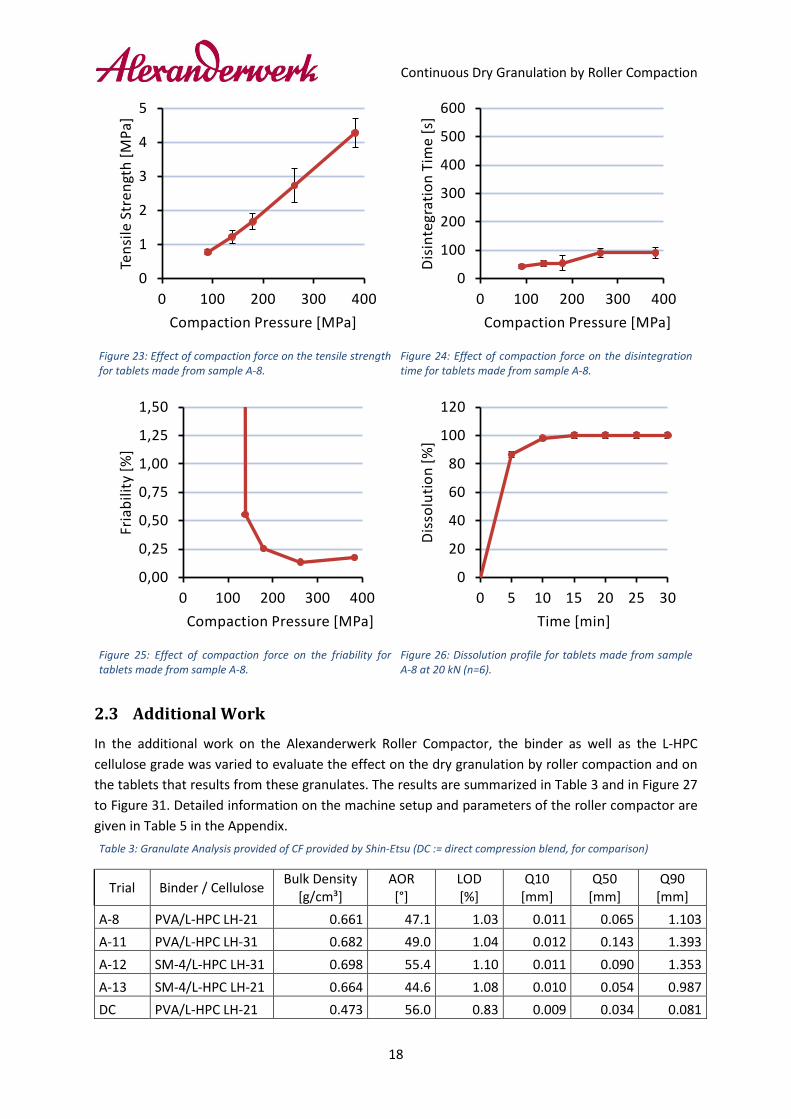
2.2.2 Evaluation of the Tablets from the Comparative Formulation Granulates of the comparative formulation processed in trial A-8 were selected with low AOR and few fines was selected for tablet compression. The improved bulk density of the sample (0.661 g/cm³) is typical for roller compaction processes. A higher bulk density of granules allows higher tablet weights when using smaller dies. The results are summarized in Figure 23 to Figure 26. The tensile strength of tablets, produced with the A-8 granulates, is above 2 MPa and therefore acceptable for pressures higher than 200 MPa, which is a typical compaction force encountered on rotary tablet presses. At the same time, an immediate release of API is maintained (100 % dissolved in less than 15 min). The tablets show excellent friability of less than 0.25 % starting from 200 MPa compaction pressure
In summary, the granules and tablet analysis shows that dry granulation by roller compaction can be used to enhance the powder flow and therefore the filling of a tablet press in comparison to the not granulated blend which showed AOR > 56 . At the same time tablets of sufficient hardness and a immediate release can be produced, even without addition of a dedicated dry binder to the dry granulation formulation. The low moisture of granules demonstrates the unique advantage when processing moisture sensitive formulations via roller compaction dry granulation.
0
100
200
300
400
500
600
0,6 0,8 1,0 1,2
D50
[μm
]
RFG Screen [mm]
D50 (at 108.4 RPM)D50 (at 50 RPM)D50 (at 100 RPM)
0
50
100
150
200
250
300
0 25 50 75 100
D50
[μm
]
Compaction Pressure [bar]
Continuous Dry Granulation by Roller Compaction
18
Figure 23: Effect of compaction force on the tensile strength for tablets made from sample A-8.
Figure 24: Effect of compaction force on the disintegration time for tablets made from sample A-8.
Figure 25: Effect of compaction force on the friability for tablets made from sample A-8.
Figure 26: Dissolution profile for tablets made from sample A-8 at 20 kN (n=6).
2.3 Additional Work
In the additional work on the Alexanderwerk Roller Compactor, the binder as well as the L-HPC cellulose grade was varied to evaluate the effect on the dry granulation by roller compaction and on the tablets that results from these granulates. The results are summarized in Table 3 and in Figure 27 to Figure 31. Detailed information on the machine setup and parameters of the roller compactor are given in Table 5 in the Appendix. Table 3: Granulate Analysis provided of CF provided by Shin-Etsu (DC := direct compression blend, for comparison)
Trial Binder / Cellulose Bulk Density [g/cm³]
AOR [°]
LOD [%]
Q10 [mm]
Q50 [mm]
Q90 [mm]
A-8 PVA/L-HPC LH-21 0.661 47.1 1.03 0.011 0.065 1.103 A-11 PVA/L-HPC LH-31 0.682 49.0 1.04 0.012 0.143 1.393 A-12 SM-4/L-HPC LH-31 0.698 55.4 1.10 0.011 0.090 1.353 A-13 SM-4/L-HPC LH-21 0.664 44.6 1.08 0.010 0.054 0.987 DC PVA/L-HPC LH-21 0.473 56.0 0.83 0.009 0.034 0.081
0
1
2
3
4
5
0 100 200 300 400
Tens
ile S
tren
gth
[MPa
]
Compaction Pressure [MPa]
0
100
200
300
400
500
600
0 100 200 300 400
Dis
inte
grat
ion
Tim
e [s
]
Compaction Pressure [MPa]
0,00
0,25
0,50
0,75
1,00
1,25
1,50
0 100 200 300 400
Fria
bilit
y [%
]
Compaction Pressure [MPa]
0
20
40
60
80
100
120
0 5 10 15 20 25 30
Dis
solu
tion
[%]
Time [min]
Continuous Dry Granulation by Roller Compaction
19
It was found, that the granulate particles are coarser when LH-31 is used compared to when LH-21 is used. This can be explained by higher specific surface area of the LH-31 (LH-31 is a micronized grade) which provides more bonding area within the powder blend during roller compaction. In addition, it was found, that the PVA produces coarser granulates than SM-4, even though the effect of the binder is much smaller than for the cellulose grade. The AOR was decreased for all roller compacted samples, except for the samples produced with SM-4 and LH-31. Here it is similar to the non-granulated direct compression blend, even though the bulk density is significantly higher.
Upon compression of these 4 trials on the tablet press, it was found that the changes in the formulation had only a minor effect on the tensile strength and on the dissolution time, Figure 27 and Figure 30. Only at a very high compaction pressure of 526 MPa, the tensile strength of tablet from the PVA / L-HPC LH-31 granulate dropped in comparison to the other samples. This is attributed to over-compression on the tablet press. The friability does become lower that 0.25 % for all formulations when the compaction pressure is larger than 250 MPa. The overall lowest friability (0.01 %) was reached using SM-4 / L-HPC LH-21 at 400 MPa. The dissolution time was higher, when the SM-4 was used, see Figure 28.
Overall it can be concluded, that of the two tested binders, due to the low friability and the increased disintegration time SM-4 is the favorable binder in dry granulation by roller compaction. Even though tablets of sufficient tensile strength (>2 MPa) and friability (<1%) can be achieved with every tested formulation on the roller compactor.

Continuous Dry Granulation by Roller Compaction
20
Figure 27: Effect of compaction force on the tensile strength for tablets made, using different dry granulation blend.
Figure 28: Effect of compaction force on the disintegration time for tablets made, using different dry granulation blend.
Figure 29: Effect of compaction force on the friability for tablets made, using different dry granulation blend.
Figure 30: Dissolution profile for tablets made, using different dry granulation blend at 20 kN (n=6).
Figure 31: Particle size distribution according to Camsizer for granulates made, using different dry granulation blends.
0
1
2
3
4
5
6
0 200 400 600
Tens
ile S
tren
gth
[MPa
]
Compaction Force [MPa]
050
100150200250300350
0 200 400 600
Dis
inte
grat
ion
Tim
e [s
]
Compaction Force [MPa]
0,0
0,5
1,0
1,5
0 200 400 600
Fria
bilit
y [%
]
Compaction Force [MPa]
0
20
40
60
80
100
120
0 5 10 15 20 25 30
Dis
solu
tion
[%]
Time [min]
0
25
50
75
100
0,0 0,5 1,0 1,5
Q3
[%]
xc,min [mm]
PVA/L-HPC LH-21
PVA/L-HPC LH-31
SM-4/L-HPC LH-31
SM-4/L-HPC LH-21
DC Blend

Continuous Dry Granulation by Roller Compaction
21
3 Summary This case-study is part of a seminar in which different granulation technologies are compared, regarding their behavior on the tablet press. The focus of this study was on the dry granulation by roller compaction of different paracetamol blends using the Alexanderwerk WP 120 Pharma roller compactor. First trials were carried out, using a comparative formulation (CF), that was used on all different granulation technologies. The CF comprised of paracetamol, lactose, low-substituted hydroxypropyl cellulose L-HPC LH-21 and PVA JVP PE05-JPS as a binder. Using the CF the effect of granulation process parameters as pressure and granulator settings were tested. It was found, that for this respective formulation the particle size is shifted towards coarser particles, when the pressure increases up to a certain level, when larger screens are used in the RFG and when the granulator speed increases. The lowest AOR (47°) in combination with a coarse PSD (Q50: 0.065 mm according to Camsizer) for the CF was reached in trial A-8. The settings were: 85 bar compaction pressure, 2 mm roller gap, 1.6 mm screen mesh in the fine granulator and 100 RPM granulator speed of the fine granulator. The bulk density at this setting was 0.661 g/cm³. Even though the PVA binder used was is not a dedicated binder for dry granulation it was possible to produce immediate release tables with acceptable tensile strength (>2 MPa) and low friability (<0.25 %) when compaction pressures >200 MPa where applied on the tablet press.
Additional trials were carried out, where the L-HPC grade (LH-21 or LH-31) and the binder (PVA or METOLOSE® SM-4) was varied. It was found, that the coarsest granulate was produced using PVA in combination with LH-31. However, the changes within the formulation had little to no effect on the resulting tensile strength and dissolution time of the tablets (always below 15 minutes). However, the disintegration time was slightly increased and the friability was reduced, when SM-4 was selected as a dry binder. The bulk density of the granulates produced from different formulation was always >0.66 g/cm³ which allows enough material to be filled into the tablet press die.
In summary, it can be concluded, that SM-4 is the better binder in comparison with PVA for dry granulation by roller compaction. However, with all tested formulations an immediate release paracetamol tablets of sufficient tensile strength and low disintegration time can be produced on the Alexanderwerk WP 120 Pharma Roller Compactor The higher bulk density of granules produced in roller compaction process allows a higher tablet weight to be achieved using smaller dies. The absence of moisture in the granulation process allows for easy processing of moisture sensitive formulations. In addition, the continuous granulation process makes the roller compaction dry granulation suitable for continuous manufacturing lines.
Continuous Dry Granulation by Roller Compaction
22
4 References
[1] M. Yu, C. Omar, A. Schmidt, J. D. Lister and A. D. Salman, "Improving feeding powder distribution to the compaction zone in the roller compaction," European Journal of Pharmaceutics and Biopharmaceutics, pp. 57-68, 07 2018.
[2] A. M. Miguélez-Morán, C.-Y. Wu, H. Dong and J. P. Seville, "Characterisation of density distributions in roller-compacted ribbons using micro-indentation and X-ray micro-computed tomography," European Journal of Pharmaceutics and Biopharmaceutics, pp. 173-182, 12 2009.
[3] W.-J. Sun, S. Kothari and C. C. Sun, "The relationship among tensile strength, Young's modulus, and indentation hardness of pharmaceutical compacts," Powder Technology, pp. 1-6, 02 2018.
[4] A. Mazor, L. Orefice, A. Michrafy, A. de Ryck and J. G. Khinast, "A combined DEM & FEM approach for modelling roll compaction process," Powder Technology, 04 2017.
[5] R. W. Miller, "Roller Compaction Technology," in Handbook of Pharmaceutical Granulation Technology, New York, Marcel Dekker, 1997, pp. 127-132.
[6] R. W. Miller, "Roller Compaction Technology," in Handbook of Pharmaceutical Granulation Technology, New York, USA, Marcel Dekker, 2010, pp. 163-182.
[7] E. Hadzovic, G. Betz, S. Hadzidedic, S. K. El-Arini and H. Leuenberger, "Roller compaction of different pseudopolymorphic forms of Theophylline: Effect onc ompressibility and tablet properties," International Journal of Pharmaceutics, pp. 53-62, 06 2010.
[8] M. Allesø, P. Holm, J. M. Carstensen and R. Holm, "Quantitative surface topography assessment of directly compressed and roller compacted tablet cores using photometric stereo image analysis," European Journal of Pharmaceutical Sciences, pp. 79-87, 01 2016.
[9] C. Bacher, P. Olsen, P. Bertelsen, J. Kristensen and J. Sonnergaard, "Improving the compaction properties of roller compacted calcium carbonate," International Journal of Pharmaceutics, pp. 115-123, 05 2007.
[10] C. S. Omar, M. J. Hounslow and A. D. Salman, Implementation of an online thermal imaging to study the effect of process parameters of roller compactor, Sheffield, 2017.
[11] G. Reynolds, R. Ingale, R. Roberts, S. Kothari and B. Gururajan, "Practical application of roller compaction process modeling," Computers and Chemical Engineering, pp. 1049-1057, 34 2010.
[12] A. R. Muliadi, J. D. Lister and C. R. Wassgren, "Validation of 3-D finite element analysis for predicting the density distribution of roll compacted pharmaceutical powder," Powder Technology, pp. 386-399, 237 2013.
Continuous Dry Granulation by Roller Compaction
23
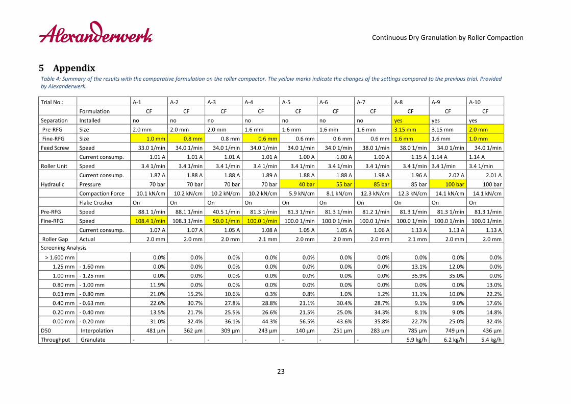
5 Appendix Table 4: Summary of the results with the comparative formulation on the roller compactor. The yellow marks indicate the changes of the settings compared to the previous trial. Provided by Alexanderwerk.
Trial No.: A-1 A-2 A-3 A-4 A-5 A-6 A-7 A-8 A-9 A-10 Formulation CF CF CF CF CF CF CF CF CF CF Separation Installed no no no no no no no yes yes yes Pre-RFG Size 2.0 mm 2.0 mm 2.0 mm 1.6 mm 1.6 mm 1.6 mm 1.6 mm 3.15 mm 3.15 mm 2.0 mm Fine-RFG Size 1.0 mm 0.8 mm 0.8 mm 0.6 mm 0.6 mm 0.6 mm 0.6 mm 1.6 mm 1.6 mm 1.0 mm Feed Screw Speed 33.0 1/min 34.0 1/min 34.0 1/min 34.0 1/min 34.0 1/min 34.0 1/min 38.0 1/min 38.0 1/min 34.0 1/min 34.0 1/min Current consump. 1.01 A 1.01 A 1.01 A 1.01 A 1.00 A 1.00 A 1.00 A 1.15 A 1.14 A 1.14 A Roller Unit Speed 3.4 1/min 3.4 1/min 3.4 1/min 3.4 1/min 3.4 1/min 3.4 1/min 3.4 1/min 3.4 1/min 3.4 1/min 3.4 1/min Current consump. 1.87 A 1.88 A 1.88 A 1.89 A 1.88 A 1.88 A 1.98 A 1.96 A 2.02 A 2.01 A Hydraulic Pressure 70 bar 70 bar 70 bar 70 bar 40 bar 55 bar 85 bar 85 bar 100 bar 100 bar Compaction Force 10.1 kN/cm 10.2 kN/cm 10.2 kN/cm 10.2 kN/cm 5.9 kN/cm 8.1 kN/cm 12.3 kN/cm 12.3 kN/cm 14.1 kN/cm 14.1 kN/cm Flake Crusher On On On On On On On On On On Pre-RFG Speed 88.1 1/min 88.1 1/min 40.5 1/min 81.3 1/min 81.3 1/min 81.3 1/min 81.2 1/min 81.3 1/min 81.3 1/min 81.3 1/min Fine-RFG Speed 108.4 1/min 108.3 1/min 50.0 1/min 100.0 1/min 100.0 1/min 100.0 1/min 100.0 1/min 100.0 1/min 100.0 1/min 100.0 1/min Current consump. 1.07 A 1.07 A 1.05 A 1.08 A 1.05 A 1.05 A 1.06 A 1.13 A 1.13 A 1.13 A Roller Gap Actual 2.0 mm 2.0 mm 2.0 mm 2.1 mm 2.0 mm 2.0 mm 2.0 mm 2.1 mm 2.0 mm 2.0 mm Screening Analysis
> 1.600 mm 0.0% 0.0% 0.0% 0.0% 0.0% 0.0% 0.0% 0.0% 0.0% 0.0% 1.25 mm - 1.60 mm 0.0% 0.0% 0.0% 0.0% 0.0% 0.0% 0.0% 13.1% 12.0% 0.0% 1.00 mm - 1.25 mm 0.0% 0.0% 0.0% 0.0% 0.0% 0.0% 0.0% 35.9% 35.0% 0.0% 0.80 mm - 1.00 mm 11.9% 0.0% 0.0% 0.0% 0.0% 0.0% 0.0% 0.0% 0.0% 13.0% 0.63 mm - 0.80 mm 21.0% 15.2% 10.6% 0.3% 0.8% 1.0% 1.2% 11.1% 10.0% 22.2% 0.40 mm - 0.63 mm 22.6% 30.7% 27.8% 28.8% 21.1% 30.4% 28.7% 9.1% 9.0% 17.6% 0.20 mm - 0.40 mm 13.5% 21.7% 25.5% 26.6% 21.5% 25.0% 34.3% 8.1% 9.0% 14.8% 0.00 mm - 0.20 mm 31.0% 32.4% 36.1% 44.3% 56.5% 43.6% 35.8% 22.7% 25.0% 32.4%
D50 Interpolation 481 μm 362 μm 309 μm 243 μm 140 μm 251 μm 283 μm 785 μm 749 μm 436 μm Throughput Granulate - - - - - - - 5.9 kg/h 6.2 kg/h 5.4 kg/h

Continuous Dry Granulation by Roller Compaction
24
Table 5: Summary of the additional work on the roller compactor. The yellow marks indicate the changes of the settings to the previous trial. Provided by Alexanderwerk.
Trial No.: A-8 A-11 A-12 A-13 Formulation CF AW-AF1 AW-AF2 AW-AF3 Binder PVA PVA SM4 SM4 L-HPC LH 21 LH31 LH 31 LH 21 Bulk density Raw Material 512 g/l 0.542 kg/l 0.538 kg/l 0.512 kg/l Separation Installed yes yes yes yes Pre-RFG Size 3.15 mm 3.15 mm 3.15 mm 3.15 mm Fine-RFG Size 1.6 mm 1.6 mm 1.6 mm 1.6 mm
Feed Screw Speed 38.0 1/min 31.0 1/min 33.0 1/min 33.0 1/min
Current consump. 1.15 A 1.10 A 1.09 A 1.10 A Roller Unit Speed 3.4 1/min 3.4 1/min 3.4 1/min 3.4 1/min Current consump. 1.96 A 2.02 A 2.05 A 1.96 A Hydraulic Pressure 85 bar 85 bar 85 bar 85 bar Compaction Force 12.3 kN/cm 12.3 kN/cm 12.3 kN/cm 12.3 kN/cm Flake Crusher On On On On Pre-RFG Speed 81.3 1/min 81.3 1/min 81.3 1/min 81.3 1/min Fine-RFG Speed 100.0 1/min 100.0 1/min 100.0 1/min 100.0 1/min Current consump. 1.13 A 1.13 A 1.12 A 1.14 A Roller Gap Actual 2.0 mm 2.0 mm 2.0 mm 2.0 mm Screening Analysis
> 1.600 mm 0.0% 0.5% 0.0% 0.0% 1.25 mm - 1.60 mm 13.1% 25.9% 22.5% 11.1% 1.00 mm - 1.25 mm 35.9% 19.0% 17.9% 20.6% 0.80 mm - 1.00 mm 0.0% 13.8% 13.3% 14.5% 0.63 mm - 0.80 mm 11.1% 7.9% 8.7% 11.6% 0.40 mm - 0.63 mm 9.1% 7.4% 7.8% 8.4% 0.20 mm - 0.40 mm 8.1% 5.8% 6.4% 9.8% 0.00 mm - 0.20 mm 22.7% 19.6% 23.4% 24.0%
D50 Interpolation 785 μm 935 μm 855 μm 744 μm Throughput Granulate 5.9 kg/h - - -


