338


CONTRACT DOCUMENTS FOR PROJECT 0631A, DIVISION 026
REHABILITATION AND REPAINTING OF ANNANDALE RESERVOIRS #1 AND #2
OWNER FAIRFAX COUNTY WATER AUTHORITY
d/b/a: FAIRFAX WATER 8570 Executive Park Avenue
Fairfax, Virginia 22031 Tel. (703) 289-6265 Fax (703) 289-6262
FAIRFAX WATER Invitation for Bid No. 20-053
October 2020

SECTION 00010
TABLE OF CONTENTS
DRAWINGS No. Title AT-001 Site Plan - Annandale #1 and #2 (for general information only) AT-002 Existing Tank Plan - Annandale #1 AT-003 Existing Tank Plan - Annandale #2 AT-004 Proposed Tank Plan - Annandale #1 AT-005 Proposed Tank Plan - Annandale #2 AT-006 Conduits Detail #1 AT-007 Conduits Detail #2 AT-008 Conduits Detail #3 A1 Annandale Reservoirs Overview of Modifications AB Antenna Mounting Support CRV Clog-Resistant Roof Vent, Sheets 1-4 LR Exterior Ladder LV Vandal Deterrent OFP Overflow OFW Overflow Weir Box RA Angle Bracing Between Rafters RM Roof Manhole SM1 Shell Manhole - Annandale Reservoir #1 SM2 Shell Manhole - Annandale Reservoir #2 SMD Shell Manhole Davit SRA1 Roof Platform and Safety Railing – Annandale Reservoir #1 SRA2 Roof Platform and Safety Railing – Annandale Reservoir #2 SRA3 Roof Platform and Safety Railing SRA4 Roof Platform Floor SRA5 Roof Manhole Safety Railing SWS Swivel Anchor TO Threadolet SPECIFICATIONS DIVISION 1 – GENERAL REQUIREMENTS Section Title 01110 Summary of Work 01120 Coordination 01130 Standards and Regulations 01140 Limitations on Sequence of Construction 01200 Measurement and Payment 01250 Contract Modification Procedures 01260 Standard Project Forms 01290 Applications for Payment 01310 Project Meetings 01320 Construction Schedule

01330 Submittals 01410 Regulatory Requirements 01420 References 01450 Quality Control 01500 Construction Facilities and Temporary Controls 01600 Materials and Equipment 01615 Wire and Equipment Index 01630 Product Options and Substitutions 01710 Cleaning 01730 Cutting and Patching 01770 Contract Closeout 01782 Operation and Maintenance Data 01800 Equipment and System Training DIVISION 2 – SITE CONSTRUCTION Section Title 02370 Erosion and Sediment Control 02675 Disinfection of Water Distribution Systems 02920 Lawns and Grasses DIVISION 9 – FINISHES Section Title 09800 General Specifications for Coating Systems 09871 Exterior Coating System for Steel Storage Tank 09872 Interior Coating System for Steel Storage Tank 09880 Concrete Coating DIVISION 13 – SPECIAL CONSTRUCTION Section Title 13201 Annandale Reservoir #1 Rehabilitation 13202 Annandale Reservoir #2 Rehabilitation DIVISION 16 – ELECTRICAL Section Title 16111 Conduit, Fittings, and Supports ATTACHMENTS Title Summarized Tank Information Sheet – Annandale Reservoir #1 Summarized Tank Information Sheet – Annandale Reservoir #2 Pre-Job Soil Sampling Procedure & Chain of Custody Form

Post-Job Soil Sampling Procedure & Chain of Custody Form Spent Abrasive Sampling Procedure and Chain of Custody Form Job Safety Analysis Form Contractor Safety Checklist Daily Jobsite Safety Survey Report Submittal Checklist Submittal Cover Sheet Photographs from Annandale Reservoir #1 Evaluation Report 6-23-17 and 10-31-17 (for general information only) Photographs from Annandale Reservoir #2 Evaluation Report 10-31-17 and 5-22-18 (for general information only)
END OF SECTION 00010

INDEX OF DRAWINGS
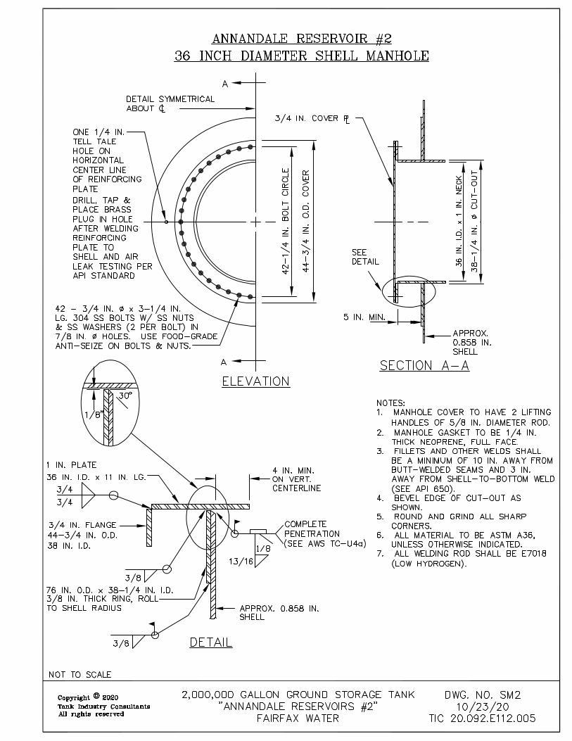
No. Title AT-001 Site Plan - Annandale #1 and #2 (for general information only) AT-002 Existing Tank Plan - Annandale #1 AT-003 Existing Tank Plan - Annandale #2 AT-004 Proposed Tank Plan - Annandale #1 AT-005 Proposed Tank Plan - Annandale #2 AT-006 Conduits Detail #1 AT-007 Conduits Detail #2 AT-008 Conduits Detail #3 A1 Annandale Reservoirs Overview of Modifications AB Antenna Mounting Support CRV Clog-Resistant Roof Vent, Sheets 1-4 LR Exterior Ladder LV Vandal Deterrent OFP Overflow OFW Overflow Weir Box RA Angle Bracing Between Rafters RM Roof Manhole SM1 Shell Manhole - Annandale Reservoir #1 SM2 Shell Manhole - Annandale Reservoir #2 SMD Shell Manhole Davit SRA1 Roof Platform and Safety Railing – Annandale Reservoir #1 SRA2 Roof Platform and Safety Railing – Annandale Reservoir #2 SRA3 Roof Platform and Safety Railing SRA4 Roof Platform Floor SRA5 Roof Manhole Safety Railing SWS Swivel Anchor TO Threadolet

400
400
402
400
402
404
402
404
402
404
404
402
395
390
385
380
404
395
390
385
385
400
400
402
402
Rip Rap
INTERMEDIATEPOE
SCHOOL
12" Storm
80' -
12"
RC
P
12" S
TOR
M
S
S
S
S
156' - 12" RCP
Kandel Court
TANK #22MG
TANK #35MG
GRA
VEL
D
RIVE
16"
16"16"
16"30"
30"
30"
36" DIP
36" D
IP
36" D
IP
30" P
CCP
12" A
CP
12" A
CP
30" P
CCP
36" D
IP
36" D
IP
30" P
CCP
24" P
CCP
24" P
CCP30" PCCP
30" D
IP
24" DIP
20" PCCP24" PCCP
24" PCCP
20" PCCP
6"
30"
36"
30"
6"
Control ValveVault
PRVPRV
Check Valve
Ball Valve
Ball Valve
UNDERGROUNDELECTRIC
ELECTRICALEQUIPMENT
CONCRETE PAD
ELECTRICALEQUIPMENTCONCRETE PAD
CHAIN LINKFENCE
ELECTRICALEQUIPMENT
ELECTRICALEQUIPMENT
ELECTRICALBOX ON 6" x 6"WOOD POST
CHAIN LINK FENCE (LOCATEDAPPROX. ALONG PROPERTYLINE)
PROPERTY LINE (TYP)
FIREHYDRANT
LIGHT ONPOLE #6489V
AT&TANTENNA
OVERHEAD AT&T LINES
CORROSIONCONTROL BOX
OVERHEADLINE
ELECTRICALEQUIPMENT
APPROX. LOCATION OFACCESS GATE
ELECTRICAL VAULT
EX. GATE
EX.ANTENNA
CABLE
TANK #12MG
EX. UTILITY SHED
EX. ALTITUDEVAULT
FIREHYDRANT
EX. VAULT
LIMITS OFDISTURBANCE
LIMITS OFDISTURBANCE
LIMITS OFDISTURBANCE
TREE BRANCHES SHALL NOT BETRIMMED BEYOND 15 FT. FROMTANK #1
TREE BRANCHES SHALL NOTBE TRIMMED BEYOND 15 FT.
FROM TANK #2
Feet0 20 40
PROJECT DIVISIONDRAWING
0260631A
SHEET
FAIRFAX WATERPLANNING AND ENGINEERING DIVISION
8560 ARLINGTON BOULEVARDFAIRFAX, VA 22031 ANNANDALE #1 AND #2 REHABILITATION
1 OF 1
AUGUST 2020
TAX MAP: 71-1
AT-001
SITE PLAN

COMMCOMM
COM
M
COMM
COMM
COMM
COMM
COMM
COMM
COMM
COMM
COMM
COMM
COMM
COMM
COMM
COMM
COMM
COMM
COMM
R47'-6"
EX. LEVEL TRANSDUCERINSIDE HOUSING TO BE
REMOVED AND REINSTALLEDBY FAIRFAX WATER.
EX. CONDUIT TO BEDEMOLISHED
EX. HIGH LEVEL FLOATLOCATED INSIDE ACCESSMANHOLE TO BE REMOVEDAND REINSTALLED BYFAIRFAX WATER
EX. VENTTO BE DEMOLISHED
EX. VENT
EX. VENTTO BE DEMOLISHED
EX. ANTENNA CABLESAND BRACKETS TO BE
DEMONISHED
EX. ACCESS HATCH
EX. OVERFLOW PIPETO BE DEMOLISHED
EX. RAILING TOBE DEMOLISHED
EX. RAILING TOBE DEMOLISHED
EX. RAILING TOBE DEMOLISHED
EX. RAILING TOBE DEMOLISHED
EX. LADDER TOBE DEMOLISHED
EX. ANTENNA MAST TO BEREMOVED BY FAIRFAXWATER
EX. 2'-6" SHELL MANHOLE
EX. 2'-6" SHELL MANHOLE
EX. CATHODICPROTECTION PANELTO BE DEMOLISHED
EX. ACCESS HATCHTO BE DEMOLISHED
FAIRFAX WATER
DATE:
SCALE:
DRAWING NO:
AT-00207/28/2020
1/16"=1'
EXISTING TANK PLANANNANDALE TANK #1
ANNANDALE #1 AND #2 REHABILITATION

COMM
COMM
COMM
COMM
COMM
COMM
COMM
CO
MM
R47'-6"
EX. ACCESS HATCH
EX. VENTTO BE DEMOLISHED
EX. VENT
EX. VENTTO BE DEMOLISHED
EX. OVERFLOW PIPETO BE DEMOLISHED
EX. CONDUIT TO BEDEMOLISHED
EX. HIGH LEVEL FLOATLOCATED INSIDE ACCESS
MANHOLE TO BE REMOVEDAND REINSTALLED BY
FAIRFAX WATER
EX. RAILING TOBE DEMOLISHED
EX. RAILING TOBE DEMOLISHED
EX. LADDER TOBE DEMOLISHED
EX. RAILING TOBE DEMOLISHED
EX. RAILING TOBE DEMOLISHED
EX. LEVEL TRANSDUCERINSIDE HOUSING TO BE
REMOVED AND REINSTALLEDBY FAIRFAX WATER.
EX. 2'-6" SHELL MANHOLE
EX. CATHODICPROTECTION PANEL TOBE DEMOLISHED
EX. 2'-6" SHELL MANHOLE
EX. ACCESS HATCHTO BE DEMOLISHED
FAIRFAX WATER
DATE:
SCALE:
DRAWING NO:
AT-00307/28/2020
1/16"=1"
EXISTING TANK PLANANNANDALE TANK #2
ANNANDALE #1 AND #2 REHABILITATION

R47'-6" 4'
2'-0"
2'-0"
4'-10"MIN3'-0"
MIN
2'-6"
3'-0"
MIN
3'-0"
MIN
4'-10"
2'-0"EX. LEVEL
TRANSDUCERHOUSING
PROPOSED 2'-6"SQUARE ACCESS
HATCHPROPOSED 2'-0" DIA VENT
EX. VENT
PROPOSED 2'-0" DIA VENT
EX. ACCESS HATCH
PROPOSEDRAILING
PROPOSEDRAILING
PROPOSED 3' X 3' ROOFPLATFORM
PROPOSEDELECTRICAL TROUGH. SEEDETAIL ON SHEET AT-006
PROPOSEDELECTRICAL TROUGH.SEE DETAIL ON SHEETAT-008PROPOSED
ANTENNA MAST
PROPOSED RAILING
PROPOSEDCONDUITS
PROPOSEDLADDER
EX. 2'-6" SHELL MANHOLEEX. 2'-6" SHELL MANHOLE
PROPOSEDCATHODIC
PROTECTION BOX
PROPOSEDANCHOR POINT
PROPOSEDANCHOR POINT
PROPOSED 3'-0"SHELL MANHOLE
PROPOSED 1'-4" DIA OVERFLOW PIPE
PROPOSED 2'-6"SQUARE ACCESS
HATCH
PROPOSEDRAILING
3'-0"MIN
3'-0"MIN
PROPOSED THREADOLET
BRACE WITH CARBON STEEL UNISTRUTAT 4' OC MAX. WELD TO TANK. LENGTHOF 12" (TYP)
UNISTRUT TO BE 1'-6" FROM BASE OFPROPOSED ANTENNA MAST
UNISTRUT TO BE 1'-6" FROMPROPOSED ELECTRICAL
TROUGH
FAIRFAX WATER
DATE:
SCALE:
DRAWING NO:
AT-00407/28/2020
1/16"=1"
PROPOSED TANK PLANANNANDALE TANK #1
ANNANDALE #1 AND #2 REHABILITATION

R47'-6" 4'
2'-0"
2'-0"
4'-10"MIN
3'-0"
MIN
3'-0"
MIN
3'-0"
MIN
4'-10"
2'-0"EX. LEVEL TRANSDUCER
HOUSING
EX. ACCESS HATCH
PROPOSED 2'-0" DIA VENT
EX. VENT
PROPOSED 2'-0" DIA VENT
PROPOSED 1'-4" DIA OVERFLOW PIPE
PROPOSED 2'-6"SQUARE ACCESS HATCH
PROPOSEDRAILING
PROPOSED ROOFPLATFORM
PROPOSEDLADDER
PROPOSEDELECTRICAL TROUGH.SEE DETAIL ON SHEETAT-006
PROPOSEDELECTRICAL TROUGH.SEE DETAIL ON SHEETAT-008
PROPOSED RAILING
PROPOSEDCONDUITS
PROPOSEDANTENNA MAST
PROPOSEDCATHODICPROTECTION BOX
PROPOSEDANCHOR POINT
PROPOSEDANCHOR POINT
EX. 2'-6" SHELL MANHOLE
PROPOSED 3'-0"SHELL MANHOLE
EX. 2'-6" SHELL MANHOLE
PROPOSED THREADOLET
3'-0"
MIN
BRACE WITH CARBON STEEL UNISTRUTAT 4' OC MAX. WELD TO TANK. LENGTHOF 12" (TYP)
UNISTRUT TO BE 1'-6" FROM BASE OFPROPOSED ANTENNA MAST
UNISTRUT TO BE 1'-6" FROMPROPOSED ELECTRICAL
TROUGH
FAIRFAX WATER
DATE:
SCALE:
DRAWING NO:
AT-00507/28/2020
1/16"=1"
PROPOSED TANK PLANANNANDALE TANK #2
ANNANDALE #1 AND #2 REHABILITATION

NOTES:1. BRACES SHALL BE INSTALLED NO GREATER THAN 8' SEPARATION2. CARBON STEEL UNISTRUT SHALL BE P1003 - 1-5/8" CHANNEL-P1000 VARIATION, 12 GAGE,
PLAIN FINISH OR APPROVED EQUAL.
1/4TYP.
2'-0"
BRACE WITH CARBON STEEL UNISTRUT AT 8'OC MAX.WELD TO TANK. LENGTH OF 12".
WATER TANK
THREE (3) 1-1/2" GALVANIZEDCONDUITS 4" -
EXTERIOR LADDER
FAIRFAX WATER
DATE:
SCALE:
DRAWING NO:
AT-00607/28/2020
1/2"=1"
CONDUITS DETAIL #1
ANNANDALE #1 AND #2 REHABILITATION

2'-0
"2'-0"
THREE (3) MYERS HUBS
TOP OF TANK FOUNDATION
BRACE CONDUITS AT 18"ABOVE TROUGH. CONDUITSSHALL BE A MINIMUM OF 24"
FROM LADDER
8"H X 16"W X 24"LGALVANIZED TROUGH
THREE (3) 1-1/2" GALVANIZEDCONDUITS 4" ℄-℄
EX. 30" SHELL MANHOLE
PROPOSED LADDER
FAIRFAX WATER
DATE:
SCALE:
DRAWING NO:
AT-00707/28/2020
1/2"=1"
CONDUITS DETAIL #2
ANNANDALE #1 AND #2 REHABILITATION

2'-6
"
1'-6"
8"H X 12"W X24"LGALVANIZED TROUGHWRAP OVER LID ON TOP
TANK RAILING
WATER TANK
THREE (3) 1-1/2"GALVANIZED CONDUITS4" ℄-℄.
SECURE CONDUITS
THREE (3) 1-1/2" GALVANIZEDCONDUITS 4" ℄-℄.
WATER TANK
BRACE CONDUITS AT ONE(1) FOOT FROM TRANSITIONFROM TANK SHELL TO ROOF
BRACE CONDUITS
8"H X 12"W X24"LGALVANIZED TROUGHWRAP OVER LID ONTOP
(2) STEEL UNISTRUTSWELD TO TANK.LENGTH OF 16"
(3) MYERS HUBS
(3) MYERS HUBS
FAIRFAX WATER
DATE:
SCALE:
DRAWING NO:
AT-00807/28/2020
1/2"=1"
CONDUITS DETAIL #3
ANNANDALE #1 AND #2 REHABILITATION


(4) 5/8" THREADEDSTEEL STUDS
3/4" CLASS 3000 THREADOLET PRESSURETAP, SEAL WELD TO TANK WALL.
CONTRACTOR TO CUT 1-3/16" Ø HOLE INTANK WALL
6"
6"
3"
3-1/4"
NOTE:PRESSURE TAP TO BE MOUNTED 4'-6" ABOVE GRADE
TYP.
TANK SHELL
FAIRFAX WATER
DATE:
SCALE:
DRAWING NO:
TO10/26/2020
NTS
THREADOLET OUTLET
ANNANDALE #1 AND #2 REHABILITATION
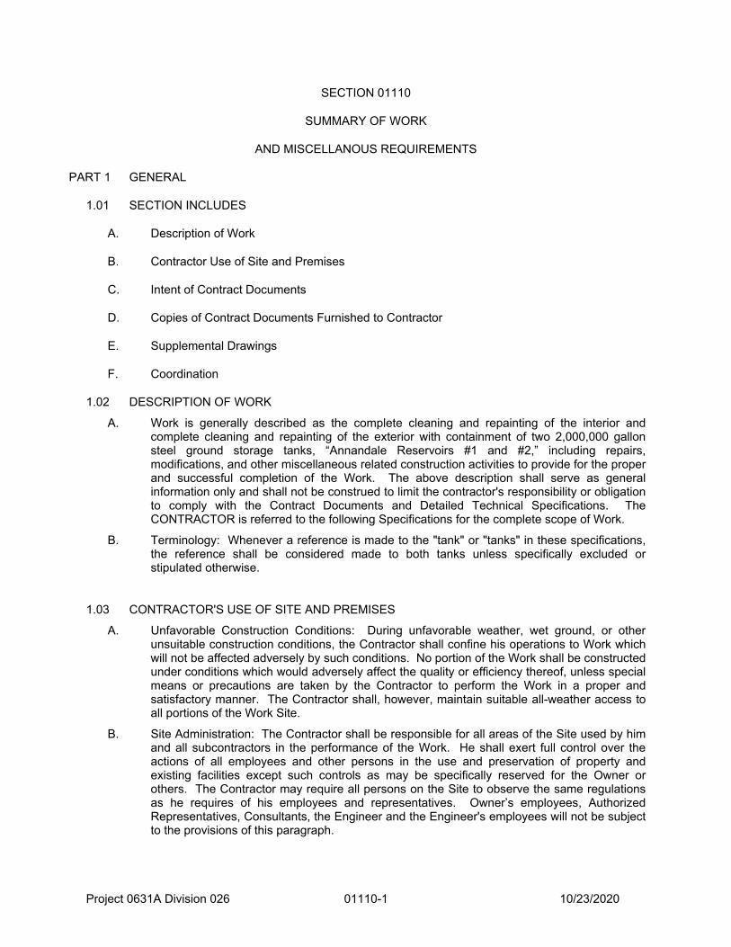
Project 0631A Division 026 01110-1 10/23/2020
SECTION 01110
SUMMARY OF WORK
AND MISCELLANOUS REQUIREMENTS
PART 1 GENERAL
1.01 SECTION INCLUDES
A. Description of Work
B. Contractor Use of Site and Premises
C. Intent of Contract Documents
D. Copies of Contract Documents Furnished to Contractor
E. Supplemental Drawings
F. Coordination
1.02 DESCRIPTION OF WORK
A. Work is generally described as the complete cleaning and repainting of the interior and complete cleaning and repainting of the exterior with containment of two 2,000,000 gallon steel ground storage tanks, “Annandale Reservoirs #1 and #2,” including repairs, modifications, and other miscellaneous related construction activities to provide for the proper and successful completion of the Work. The above description shall serve as general information only and shall not be construed to limit the contractor's responsibility or obligation to comply with the Contract Documents and Detailed Technical Specifications. The CONTRACTOR is referred to the following Specifications for the complete scope of Work.
B. Terminology: Whenever a reference is made to the "tank" or "tanks" in these specifications, the reference shall be considered made to both tanks unless specifically excluded or stipulated otherwise.
1.03 CONTRACTOR'S USE OF SITE AND PREMISES
A. Unfavorable Construction Conditions: During unfavorable weather, wet ground, or other unsuitable construction conditions, the Contractor shall confine his operations to Work which will not be affected adversely by such conditions. No portion of the Work shall be constructed under conditions which would adversely affect the quality or efficiency thereof, unless special means or precautions are taken by the Contractor to perform the Work in a proper and satisfactory manner. The Contractor shall, however, maintain suitable all-weather access to all portions of the Work Site.
B. Site Administration: The Contractor shall be responsible for all areas of the Site used by him and all subcontractors in the performance of the Work. He shall exert full control over the actions of all employees and other persons in the use and preservation of property and existing facilities except such controls as may be specifically reserved for the Owner or others. The Contractor may require all persons on the Site to observe the same regulations as he requires of his employees and representatives. Owner’s employees, Authorized Representatives, Consultants, the Engineer and the Engineer's employees will not be subject to the provisions of this paragraph.

Project 0631A Division 026 01110-2 10/23/2020
1.04 INTENT OF CONTRACT DOCUMENTS
A. Contract Documents Complementary: All Work called for in the Contract Documents applicable to this Contract, but not shown in the Drawings in their present form, or shown in the Drawings and not specifically called for in the Specifications, shall be of like effect as if shown or mentioned in both. Work not specified in either the Drawings or in the Specifications, but involved in carrying out their intent or in the complete and proper execution of the Work, is required, and shall be performed by the Contractor as though it were specifically delineated or described.
B. Omission or Silence of Contract Documents: The apparent silence of the Contract Documents as to any detail, or the apparent omission from them of a detailed description concerning any Work to be performed or materials to be furnished, shall be regarded as meaning that only the best general practice is to prevail and that only materials and Workmanship of the best quality are to be used and interpretation of these Specifications shall be made upon that basis.
1.05 DOCUMENTS FURNISHED TO CONTRACTOR
A. The Contractor will be furnished, at no cost, with a CD containing Contract Documents if required at the Preconstruction Conference. All electronic files will be provided in PDF format.
B. Copies of Contract Documents for Subcontractors: The Contractor shall, without expense to the Owner, furnish each of the subcontractors, manufacturers, and materialmen such copies of the Contract Documents as may be required for his Work.
C. Record Copy of Contract Documents: The Contractor shall keep one record copy of all Specifications, Drawings, Addenda, Change Orders, Supplemental Drawings, and Shop Drawings at the Contractor's office at the Site, if applicable, in good order and annotated to show all changes made during the construction process. The Engineer will inspect the record set of drawings and specifications on a monthly basis prior to preparation of the monthly progress payment; and in the event said drawings and specifications are not up-to-date, the monthly progress payment may be withheld until the record set of drawings and specifications are brought up-to-date. Such Documents shall be made available to the Engineer at all times and shall be delivered to the Owner upon completion of the Work.
1.06 SUPPLEMENTAL DRAWINGS
A. Supplemental Drawings: When, in the opinion of the Engineer, it becomes necessary to explain more fully the Work to be done, or to illustrate the Work further, or to show any changes which may be required, Drawings known as Supplemental Drawings with specifications pertaining thereto will be prepared by the Engineer and 10 copies thereof will be given to the Contractor.
B. Clarification Procedure: The Contractor may request a clarification of the Drawings or Specifications from the Engineer through the following procedure:
1. Forms: The standard clarification form shall be used. The upper portion of this form shall be completed and signed by the Contractor. The completed form shall be forwarded to the Engineer for a response. The Contractor should indicate a preferred reply date. The Engineer’s clarification review period shall be 14 consecutive calendar days in length and shall commence on the first calendar day immediately following the date of arrival of the clarification at the Engineer’s office. In no cases shall the Contractor’s preferred reply date be less than the 14 day review period.
a. The Contractor will assign the clarification a sequential number.
b. The Engineer will review the clarification with the appropriate parties and the Owner.
c. The Engineer will complete and sign the lower portion of the clarification.

Project 0631A Division 026 01110-3 10/23/2020
d. A copy of the completed clarification will be returned to the Contractor.
e. The completed clarification distribution will be noted on the clarification form.
f. A copy of the completed clarification will be sent to the Owner.
2. Clarification Log: A clarification log will be maintained by the Engineer and will be used to review the status of outstanding clarifications during each progress meeting.
1.07 COORDINATION
A. The Contractor shall verify all dimensions, quantities and details shown on the Drawings and Supplemental Drawings, equipment, material, finishes, and other such listings or other data received from the Engineer, and shall notify him of all errors, omissions, conflicts and discrepancies. This shall not relieve the Contractor of full responsibility for unsatisfactory Work, faulty construction, or improper operation resulting therefrom, or from rectifying such conditions at his own expense. He shall not be allowed to take advantage of any errors or omissions. All equipment, materials, finishes, and other such listings are given for the convenience of the Engineer and Contractor and are not guaranteed to be complete. The Contractor shall assume all responsibility for the making of estimates of the size, kind, and quality of materials and equipment included in Work to be done under the Contract.
1.08 CLARIFICATION REQUEST FORM
A. Clarification request form found in Section 01260 shall be used for clarification.
1.09 PIPING ALIGNMENT AND EQUIPMENT LOCATION VERIFICATIONS
A. The Contractor shall field verify the suitability of pipe alignments and equipment locations with respect to the location of existing facilities. These verifications shall be made on the submitted layout and shop drawings and before pipe and fittings are ordered from suppliers.
B. The Contractor shall be responsible to make minor adjustments of lengths or elevations in new construction necessary to suit existing facilities at no additional cost to the Owner.
PART 2 PRODUCTS
Not Used
PART 3 EXECUTION
Not Used
END OF SECTION 01110

01120-1 TIC 20.092.E112.004 & 005 Fairfax Water 23-Oct-20
SECTION 01120
COORDINATION
Copyright 2020 Tank Industry Consultants All rights reserved
. PART 1 -- GENERAL
1.1. GENERAL
A. Coordination of the Project, and each portion of the Work on this Project shall be performed by the CONTRACTOR to achieve a quality product in an expedient manner in general accordance with this Section.
1.2. PROJECT CONDITIONS
A. Safety Analysis Forms and Meetings: The CONTRACTOR is required to thoroughly review all phases of the project and complete and submit the “Job Safety Analysis Form” and the “Contractor Safety Checklist” at least 5 days prior to mobilizing to the site. Each subcontractor shall submit these forms for their work at the site as well. The CONTRACTOR shall update the forms as the project progresses or if there is a change of personnel at the site. Once the site work begins, the CONTRACTOR’S COMPETENT PERSON shall complete the “Daily Jobsite Safety Survey Report” and a “Contractor Daily Sign-in Form” to be presented to the ENGINEER at the end of each day. The CONTRACTOR shall hold daily safety meetings to discuss specific activities and events for the day and the safety ramifications. This shall be recorded each day, with a list of the attendees.
CONTRACTOR shall establish a safety program in accordance with applicable State and Federal laws. CONTRACTOR shall designate a specific individual as the Project Safety Officer and provide the necessary contact information to OWNER.
The CONTRACTOR shall, at least 5 days prior to the start of construction, submit for OWNER’s review the following information:
1. A Company Safety Plan. This plan shall include general safety information including but not limited to responsibilities, safety meetings, and reporting requirements.
2. A Site Specific Safety Plan. This plan shall identify specific safety requirements
associated with all portions of the work. 3. A Job Safety Analysis (JSA). The JSA shall be submitted for major work
activities including but not limited to traffic control, facilities demolition, and handling of waste. The JSA shall list the activity, and for each activity, shall evaluate the safety hazard and develop the recommended safety solution in terms of field procedures.
01120-2 TIC 20.092.E112.004 & 005 Fairfax Water 23-Oct-20
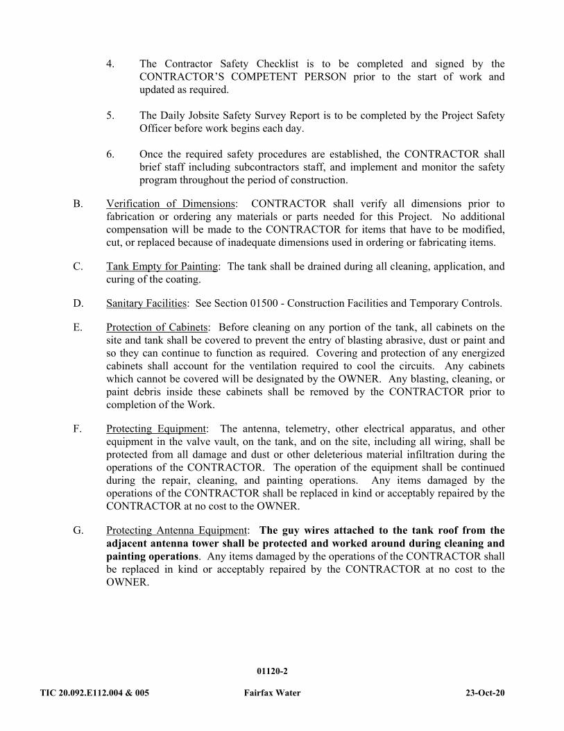
4. The Contractor Safety Checklist is to be completed and signed by the
CONTRACTOR’S COMPETENT PERSON prior to the start of work and updated as required.
5. The Daily Jobsite Safety Survey Report is to be completed by the Project Safety
Officer before work begins each day. 6. Once the required safety procedures are established, the CONTRACTOR shall
brief staff including subcontractors staff, and implement and monitor the safety program throughout the period of construction.
B. Verification of Dimensions: CONTRACTOR shall verify all dimensions prior to
fabrication or ordering any materials or parts needed for this Project. No additional compensation will be made to the CONTRACTOR for items that have to be modified, cut, or replaced because of inadequate dimensions used in ordering or fabricating items.
C. Tank Empty for Painting: The tank shall be drained during all cleaning, application, and curing of the coating.
D. Sanitary Facilities: See Section 01500 - Construction Facilities and Temporary Controls.
E. Protection of Cabinets: Before cleaning on any portion of the tank, all cabinets on the site and tank shall be covered to prevent the entry of blasting abrasive, dust or paint and so they can continue to function as required. Covering and protection of any energized cabinets shall account for the ventilation required to cool the circuits. Any cabinets which cannot be covered will be designated by the OWNER. Any blasting, cleaning, or paint debris inside these cabinets shall be removed by the CONTRACTOR prior to completion of the Work.
F. Protecting Equipment: The antenna, telemetry, other electrical apparatus, and other equipment in the valve vault, on the tank, and on the site, including all wiring, shall be protected from all damage and dust or other deleterious material infiltration during the operations of the CONTRACTOR. The operation of the equipment shall be continued during the repair, cleaning, and painting operations. Any items damaged by the operations of the CONTRACTOR shall be replaced in kind or acceptably repaired by the CONTRACTOR at no cost to the OWNER.
G. Protecting Antenna Equipment: The guy wires attached to the tank roof from the adjacent antenna tower shall be protected and worked around during cleaning and painting operations. Any items damaged by the operations of the CONTRACTOR shall be replaced in kind or acceptably repaired by the CONTRACTOR at no cost to the OWNER.

01120-3 TIC 20.092.E112.004 & 005 Fairfax Water 23-Oct-20
H. Fire Watch: All equipment and wiring shall be protected from sparks, fire, weld spatter or other potential heat and/or ignition sources. CONTRACTOR shall have a trained employee equipped with proper fire suppression equipment stationed on the ground at all times that personnel are cutting, welding, or grinding on the tank or structure.
I. Welding Repairs: All welding repairs to the interior or exterior of the tank are to be made prior to all painting operations. Any resulting burrs, weld spatter, sharp edges, corners, or rough welds which would cause difficulty in applying a holiday-free coating shall be ground smooth. This grinding is considered incidental to the welding work and is to be included in the Base Bid. After grinding, these areas shall be cleaned to produce the profile recommended by the manufacturer of the coating system. (See Welding and Cutting Precautions paragraph in Section 01130 - Standards and Regulations of these specifications for more requirements on welding.)
J. Cleaning Areas of Welding and/or Grinding: It shall be necessary to remove the coating prior to the welding of the new items to the tank. All areas that have been welded and/or ground smooth shall be cleaned prior to painting to provide proper profile for the coating system. Areas to be welded shall be welded prior to the final cleaning and painting of surfaces within the heat-affected zone. The heat-affected zone includes the opposite side of the plate or member being welded. Even if not specifically mentioned as a part of the Work under this Agreement, those areas of paint or coatings in the heat-affected zone of areas not specified to be painted shall be cleaned and painted in accordance with the requirements listed in these Detailed Technical Specifications.
K. Operation of Valves and Equipment: All operations which would include closing valves, switching, starting, stopping, or removal from service of any equipment shall be done by the OWNER'S personnel. If the CONTRACTOR desires the OWNER to close valves, operate switches, start, stop, or remove any equipment from service, the CONTRACTOR shall submit a written request to the OWNER, and if the OWNER determines that such action will not adversely affect the operations of the OWNER to provide water, then the OWNER may close valves, operate switches, start, stop, or remove the equipment from service. Such requests shall be directed to the OWNER so interruptions, if any, of the OWNER'S operations or systems will be no longer than necessary. The CONTRACTOR shall have a full complement of personnel working on a continuous basis until the Work causing the interruption is completed. All Work performed under this Agreement shall be performed in close cooperation with the OWNER.
L. Site Security: When not working on the tank or site (such as during the evening, weekends, holidays, or rain days), the CONTRACTOR shall secure all openings in the tank (greater than 8 in.), the exterior ladder, and access or rigging devices. Openings in the tank needed during ventilation of the tank shall be secured with bars, grating, or other means to allow sufficient air flow through the opening. The CONTRACTOR shall be solely responsible for the security of the site, tank, equipment, and supplies during both working and non-working hours. The OWNER will control and issue Electronic Keys to the CONTRACTOR to secure access to the general site and other locations that require shared access by both the OWNER and the CONTRACTOR personnel. See Section 01500 paragraph 1.08.F.6.

01120-4 TIC 20.092.E112.004 & 005 Fairfax Water 23-Oct-20
M. Public Safety: CONTRACTOR shall protect the public from harm caused by the CONTRACTOR'S actions and performance of the work. Prior to start of work or mobilization on site, the CONTRACTOR shall submit a site-specific Public Safety Plan based on the CONTRACTOR'S selected work methods to the ENGINEER. The Public Safety Plan shall include necessary plans and procedures to protect the general public from harm. The Plan should include such items, but not be limited to, requirements for safety exclusion zones, warning sign type and placements, protective barriers, safety and warning devices, devices for daylight and nighttime protection, and all devices required by state and local requirements. CONTRACTOR shall include a site plan summarizing the requirements of the Public Safety Plan for the specific work on the tank. CONTRACTOR'S Plan shall include the name of the Competent Person responsible for enforcing the certified Public Safety Plan.
N. Traffic Control Plan: The CONTRACTOR shall permit traffic to pass around the Project site with the least possible inconvenience or delay. The CONTRACTOR shall maintain existing roads and streets within the Project limits, keeping them open, and in good, clean, and safe condition at all times. If any traffic lane closures are necessary, the CONTRACTOR shall provide all flaggers, signs, and other traffic control devices necessary to warn and protect the public at all times from injury or damage as a result of the CONTRACTOR’S operations that may occur on highways, roads, and streets. The CONTRACTOR shall submit a traffic control plan to the ENGINEER. If no disruption of traffic is anticipated, then the CONTRACTOR shall submit a statement indicating this.
O. OWNER Performed Work: The CONTRACTOR shall cooperate with the OWNER who may be conducting other operations on or near the tank. The CONTRACTOR shall clean and paint all areas added or disturbed by the OWNER on the tank and attached accessories.
P. Furnishing and Installation of Items: Any reference in these specifications to furnishing an item or installing an item shall mean the item shall be both furnished and installed by the CONTRACTOR, unless specifically stated otherwise. Replacement shall mean the removal and legal disposal of the existing items, and furnishing and installation of the new items specified.
Q. Electrical Hazards: The CONTRACTOR shall at a minimum take the following safety measures to prevent accidents due to electrical hazards:
1. Electric Service Deactivation: The OWNER shall deactivate and lock out the electric service to the tank. The CONTRACTOR shall verify the deactivated status of the electric service to the tank prior to beginning each day's Work functions and throughout the work day. The verification of the electric service deactivation is the sole responsibility of the CONTRACTOR and shall be accomplished without supervision from the OWNER, ENGINEER, or other direct or indirect agents of the OWNER.
2. Electric Service Wiring: The CONTRACTOR shall be aware of the electric service wiring attached to and located adjacent to the tank. The CONTRACTOR shall relocate, deactivate, or provide necessary electric shock hazard protective

01120-5 TIC 20.092.E112.004 & 005 Fairfax Water 23-Oct-20
devices to prevent exposure of workers and/or equipment to electric shock hazards. The CONTRACTOR shall verify that there is sufficient electric shock hazard protection for the workers and equipment prior to and throughout each working period on the job. The verification of the electric shock hazard protection is the sole responsibility of the CONTRACTOR and shall be accomplished without supervision from the OWNER, ENGINEER, or other direct or indirect agents of the OWNER.
. PART 2 -- PRODUCTS
NOT USED
. PART 3 -- EXECUTION
3.1. QUALITY ASSURANCE
A. CONTRACTOR'S Personnel: The CONTRACTOR shall have a full complement of personnel, for the proper coordination and expedition of the work, on a continuous basis until the work is completed.
B. Notification: The CONTRACTOR shall notify the OWNER and the ENGINEER at least twenty-one (21) calendar days before starting the Work at the site. The CONTRACTOR shall reconfirm the commencement of Work with the OWNER and ENGINEER twenty-four (24) hours prior to starting work at the site.
C. Contractor Supervision: The CONTRACTOR shall provide a competent superintendent, satisfactory to the OWNER, for the Work at all times during working hours with full authority to act for him/her. The on-site superintendent shall not be replaced without prior written notification and written approval of the ENGINEER. The CONTRACTOR shall also provide an adequate staff for the proper coordination and expedition of his work. Should, in the opinion of the OWNER, any language barrier exist between the on-site superintendent and the OWNER or ENGINEER, the CONTRACTOR shall employ a qualified full-time interpreter or provide a new on-site superintendent at no additional cost to the OWNER. The on-site superintendent shall be bi-lingual if any workers are not proficient in English.
D. Work Schedule: The repairing, cleaning, and painting shall be accomplished in such a way as to minimize the length of time the tank is out of service and to minimize the number of days required for observing the repairing, cleaning, and painting operations. The CONTRACTOR'S attention is directed to the OWNER’S Requirements concerning Contract Time.
E. Times for Work: See Section 01500 paragraph 1.09.D. No repairing, cleaning or painting is to be done in the night period between sunset and sunrise. The times for Work shall also comply with local, state, and federal regulations and laws regarding days of week, noise, and interference with activities of surrounding property owners. The following exceptions may apply:

01120-6 TIC 20.092.E112.004 & 005 Fairfax Water 23-Oct-20
1. Repair Work: Should tank interior temperatures be excessive for personnel welfare during daylight hours or should other job conditions make nighttime Work beneficial to the CONTRACTOR and OWNER, written permission may be granted by the ENGINEER and OWNER to conduct repair Work at night. This permission shall only be granted if the CONTRACTOR provides the proper lighting and safety equipment and informs the neighboring occupants and property owners.
2. Cleaning and Painting Work: Should tank interior temperatures be excessive for paint application or personnel welfare during daylight hours or should other job conditions make nighttime Work beneficial to the CONTRACTOR and OWNER, written permission may be granted by the ENGINEER and OWNER to conduct Work at night. This permission shall only be granted if the necessary steel temperature, air temperature, humidity and dew point conditions are present and recorded during the application and initial drying or curing of the coatings. Also, the CONTRACTOR must provide the proper lighting and safety equipment and informs the neighboring occupants and property owners.
F. Observation: The OWNER plans to engage Tank Industry Consultants or another designated representative of the OWNER, to perform full-time observation of the repair Work, cleaning, and painting. However, the OWNER reserves the right to engage only intermittent observation services. The CONTRACTOR shall notify and make available to the ENGINEER for observation of the fit-up of any new and/or replacement parts prior to welding and following post-weld cleanup. The CONTRACTOR shall notify and make available to the ENGINEER for observation all surfaces to be coated.
G. Accessibility for Observation: All Work shall be made accessible to the ENGINEER and OWNER using the CONTRACTOR'S rigging and equipment. If assistance is required for the ENGINEER and OWNER to safely access the work, the CONTRACTOR shall furnish labor to assist the ENGINEER and OWNER. The cost of this labor shall be included in the base contract amount.
H. Attractive Nuisances and Cleanup: The job site shall be kept in a clean and safe condition at all times. Hazards or attractive nuisances shall be protected at all times. Upon completion of the Work, the job site and all nearby sites impacted by the Work activities shall be left clean of all debris or any other items resulting from the operations of the CONTRACTOR. The cost of any cleanup which must be done by the OWNER shall be deducted from funds due the CONTRACTOR. Impervious drip pans or double layers of plastic sheeting (each at least 6 mil thick) shall be placed under any compressors, generators, paint pumps, mixers, welding machines, etc. to prevent oils, solvents, organic compounds, or other contaminants from leaching into the soil. Fuel storage tanks, thinners, and other potentially hazardous materials shall be placed inside secondary containment structures to prevent contaminants from leaching into the soil. Any oils, solvents, organic compounds, or contaminants spilled on the site during the process of the Work shall be immediately removed and cleaned up by the CONTRACTOR. Any earth contaminated by a spill shall also be removed and replaced with new certified clean material to the satisfaction of the OWNER and the ENGINEER. If the OWNER has to remove the oils, solvents, organic compounds,

01120-7 TIC 20.092.E112.004 & 005 Fairfax Water 23-Oct-20
contaminants, or earth, the OWNER may deduct the costs of removal and clean-up from the total contract amount owed the CONTRACTOR.
END OF SECTION
Copyright 2020 Tank Industry Consultants All rights reserved

01130-1 TIC 20.092.E112.004 & 005 Fairfax Water 23-Oct-20
SECTION 01130
STANDARDS AND REGULATIONS
Copyright 2020 Tank Industry Consultants All rights reserved
. PART 1 -- GENERAL
1.1. REGULATORY REQUIREMENTS
A. It is consistent with the intent of these Specifications to describe those performance standards, often broad and general in nature, required to provide a complete and operating system. It shall be the responsibility of the CONTRACTOR to familiarize himself fully regarding the detailed needs and requirements of any and all regulatory agencies having jurisdiction over this work. These detailed needs and requirements shall be accommodated, as part of the Work, in every manner just as if they were prescribed in these Contract Documents and Specifications.
B. Repair Standards: All design and repairs shall be in accordance with the local building code. All design and welding shall be done in accordance with AWWA D100-11 Standard for Welded Steel Tanks for Water Storage. Where tolerances, stresses, details, and modifications are not limited or provided by the AWWA Standard, the applicable sections of the following American Petroleum Institute (API) Standards shall apply. Unless otherwise specified, all steel structural and bar components shall be fabricated from new ASTM A-36 material, all steel plate components shall be fabricated from new ASTM A-36, and all steel pipe shall be fabricated from new ASTM A-53 material.
1. API Standard 650, Welded Tanks for Oil Storage, Twelfth Edition, Includes Errata 1 (2013), Errata 2 (2014), and Addendum 1 (2014) and Addendum 2 (2016)
2. API Standard 653, Tank Inspection, Repair, Alteration, and Reconstruction, Fifth Edition (2014)
C. Painting Standards: All Work shall be done in accordance with the following requirements. The SSPC-Vis 1-02, the SSPC-Vis 3-04, and the SSPC-Vis 4-01 shall also be used taking into account staining from prior paint applications. The SSPC Standards SSPC-SP 6, Commercial Blast Cleaning and SSPC-SP 10, Near-White Blast Cleaning shall be modified to apply to each square inch instead of the approximately 9 square inch area indicated in paragraph 2.6 of each of these standards and shall be referred to hereinafter as SSPC-SP 6, Commercial Blast Cleaning (modified) and SSPC-SP 10, Near-White Blast Cleaning (modified). Where the foregoing standards, recommendations, and specifications are conflicting, said conflicts shall be brought to the attention of the ENGINEER. Manufacturer's published product data shall be adhered to unless changed in writing by the home office of the manufacturer.

01130-2 TIC 20.092.E112.004 & 005 Fairfax Water 23-Oct-20
1. SSPC: The Society for Protective Coatings (SSPC)
a. Steel Structures Painting Manual (Volume 1, 4th Edition and Volume 2, 2012 Edition, including Commentary Sections and Appendices).
b. SSPC-AB 1 “Mineral and Slag Abrasives”
c. SSPC-AB 2 “Specification for Cleanliness of Recycled Ferrous Metallic Abrasives”
d. SSPC-AB 3 “Newly Manufactured or Re-Manufactured Steel Abrasives”
e. SSPC-VIS 1-02 "Visual Standard for Abrasive Blast Cleaned Steel"
f. SSPC-VIS 3-04 "Visual Standard for Power- and Hand-Tool Cleaned Steel"
g. SSPC-VIS 4-01 "Guide and Reference Photographs for Steel Surfaces Prepared by Waterjetting"
h. SSPC-VIS 5-01 "Guide and Reference Photographs for Steel Surfaces Prepared by Wet Abrasive Blast Cleaning"
i. SSPC-Guide 6 (CON) “Guide for Containing Debris Generated During Paint Removal Operations”
j. SSPC-PA 2 “Measurement of Dry Paint Thickness with Magnetic Gages”
k. SSPC-PA Guide 10 “Guide to Safety and Health Requirements for Industrial Painting Projects”
l. SSPC-SP 12, Surface Preparation and Cleaning of Steel and Other Hard Materials by High- and Ultrahigh-Pressure Water Jetting Prior to Recoating
m. SSPC-SP 13, Surface Preparation of Concrete
n. SSPC-SP 14, Industrial Blast Cleaning
2. American Water Works Association Standards
a. AWWA D100-11, Standard for Welded Steel Tanks for Water Storage
b. AWWA D102-17, Standard for Painting Steel Water-Storage Tanks
c. AWWA C652-19, Disinfection of Water-Storage Facilities
3. NSF International (NSF)
a. ANSI/NSF Standard 61 "Drinking Water System Components - Health Effects"

01130-3 TIC 20.092.E112.004 & 005 Fairfax Water 23-Oct-20
4. the paint manufacturer's published product data
5. these Detailed Technical Specifications
D. Confined Space Entry: The CONTRACTOR shall comply with and have documented Confined Space Entry Procedures available at the tank site at all times as required by OSHA 29 CFR 1926 Subpart AA. The CONTRACTOR shall also comply with any state and/or local requirements which are more restrictive than the federal requirements.
E. Compliance with Environmental Regulations: Compliance with local, state and federal regulations concerning emissions or disposal of solid, particulate, liquid, or gaseous matter as a result of the cleaning, painting, or other operations under this Agreement shall be the responsibility of the CONTRACTOR. This compliance shall be accomplished without supervision from the OWNER, ENGINEER, or other direct or indirect agents of the OWNER. No additional compensations for changes in the laws, regulations, or the interpretation thereof shall be granted by the OWNER. No burning of trash (including abrasive bags or other paper or wood products) on the site shall be permitted. All shielding, abrasive retrieval, or other methods of using precautions required by the regulating agencies shall also be accomplished at no additional cost to the OWNER unless otherwise provided herein. Any fines imposed on the OWNER or ENGINEER by any regulatory agency as a result of the CONTRACTOR'S noncompliance with environmental regulations shall be paid or reimbursed by the CONTRACTOR.
F. Safety and Health: The CONTRACTOR shall comply with safe working practices for abrasive blasting, cleaning, burning, welding, and handling lead-based and nonlead-based coated steel, and all health and safety regulations and requirements of Federal OSHA (specifically OSHA Standard for Construction Industry, 29 CFR 1926.62, entitled “Lead Exposure in Construction; Interim Final Rule,” regarding occupational exposure to lead, and 29 CFR 1926.1126, entitled “Chromium (VI),” regarding occupational exposure to hexavalent chromium), state and local health regulatory agencies, Safety Data Sheets (SDS), SSPC-PA Guide 10, and the paint and abrasive manufacturers. This compliance shall be accomplished without supervision from the OWNER, ENGINEER, or other direct or indirect agents of the OWNER. Should vents, holes, rigging attachments, or any other modification, cutting, or welding be required to meet safety standards or otherwise accomplish the Work, they may be accomplished at the expense of the CONTRACTOR upon submitting of details in writing to, and with subsequent permission by the ENGINEER.
G. Rigging Attachments: All rigging attachments present on the tank shall be carefully evaluated by the CONTRACTOR immediately prior to use for the type and magnitude of loads which CONTRACTOR intends to impose on them. Any rigging attachments installed on the tank by the CONTRACTOR shall be removed at the completion of the Work and areas damaged by the removal of these attachments shall be cleaned and painted in accordance with these specifications. The CONTRACTOR assumes all responsibility for use of any existing or added attachments.
H. Welder's Certification: All welders and welding operators shall be certified in accordance with ASME, Section IX or AWS D1.1-96 (tests as described in AWS B2.1) to the procedures and processes required to accomplish the Work. Welder's certification

01130-4 TIC 20.092.E112.004 & 005 Fairfax Water 23-Oct-20
papers shall be furnished to the ENGINEER for review prior to the commencement of welding on the tank.
I. Welding and Cutting Precautions: No welding or flame cutting through the existing coating system shall be permitted, unless adequate worker protection is provided in accordance with the instructions in ANSI Z49.1, "Safety in Welding and Cutting," OSHA Standard for Construction Industry, 29 CFR 1926.62 entitled "Lead Exposure in Construction; Interim Final Rule," and 29 CFR 1926.1126, entitled “Chromium (VI),” regarding occupational exposure to hexavalent chromium.
J. Authority of CONTRACTOR'S COMPETENT PERSON(S): The CONTRACTOR'S COMPETENT PERSON(S) shall have the complete support of top management and written authority to ensure these operations are carried out in accordance with compliance plans and governmental regulations, independent of production pressures. To ensure independence, CONTRACTOR'S COMPETENT PERSON(S) shall report directly to the headquarters office and not to the site foreman. The CONTRACTOR'S COMPETENT PERSON(S) may have additional responsibilities and carry out other work assignments, but shall not routinely be a member of the crew that actually performs surface preparation work.
K. Responsibility of CONTRACTOR'S COMPETENT PERSON(S): CONTRACTOR'S COMPETENT PERSON(S) shall be responsible for overseeing surface preparation operations without supervision of the OWNER and/or ENGINEER. Responsibilities shall include:
1. Monitoring effectiveness and ensuring the continued integrity of environmental controls.
2. Supervising worker exposure monitoring.
3. Ensuring that a hazard communication program has been conducted for the CONTRACTOR'S personnel on site.
4. Ensuring that the Confined Space Entry Procedures are followed.
5. Ensuring that employees are wearing personal protective equipment and are trained in the use of such equipment and in the use of exposure control methods, personal hygiene facilities, respiratory protection, and decontamination practices.
6. Ensuring that employees are utilizing fall protection and are trained in accordance with all OSHA regulations.
7. Daily inspection and approval of the rigging equipment and scaffolding utilized.
8. Ensuring that the engineering controls in use are in operating condition and functioning properly.
9. Ensuring that fugitive emissions to air, water, or soil are minimized and that handling of all waste streams is in compliance with applicable regulations and contract specifications.

01130-5 TIC 20.092.E112.004 & 005 Fairfax Water 23-Oct-20
10. Controlling access to the work site and ensuring that contaminated control boundaries are marked off.
11. Maintaining project documentation.
L. Medical Surveillance: The CONTRACTOR shall institute a medical surveillance program in complete accordance with "OSHA Standard for Construction Industry, 29 CFR 1926.62 entitled "Lead Exposure in Construction; Interim Final Rule," and 29 CFR 1926.1126, entitled “Chromium (VI),” regarding occupational exposure to hexavalent chromium or more restrictive regulations. As part of the program, the CONTRACTOR shall make available biological monitoring in the form of blood sampling and analysis for lead. The costs of biological monitoring shall be paid for by the CONTRACTOR. The CONTRACTOR'S medical surveillance program shall be submitted to the ENGINEER and OWNER prior to award of the Contract and shall be submitted to the ENGINEER in the field during the Work.
M. Air Sampling Professional: The CONTRACTOR shall provide an Air Sampling Professional, on site at all times during which lead-based paint removal is being performed to confirm compliance with applicable OSHA regulations. The Air Sampling Professional shall observe, be aware of, and comment on general work site conditions which relate to the profession of industrial hygiene. The Air Sampling Professional shall document daily work activities and recommendations pertaining to the lead removal work. Of utmost importance is for the Air Sampling Professional to continuously observe via visual inspections with the unaided eye for visible emissions emitted from the lead work area. Field notes shall be maintained by the Air Sampling Professional as the permanent in-house record of on-site coverage and sampling services. Air Sampling Professional shall perform sampling of lead concentrations inside and outside of the Lead Control Area, in a manner which is representative of the airborne concentrations of lead and chromium present at a given point in time. Area monitoring results cannot be used to estimate worker exposure. Employee exposures must be measured by personal air monitoring only, as required by 29 CFR 1926.62 and 1926.1126. CONTRACTOR shall conduct all lead removal activities so that the release of paint chips/dust/debris onto the unprotected ground does not occur. Abrasive blasting operations will be suspended when high wind direction and speeds result in a potential release of airborne dust from the containment system. Visible airborne emissions are prohibited and are cause for immediate project shutdown. If at any time, work conditions present a potentially serious hazard (e.g., work conditions present visible, fugitive emissions, airborne lead concentrations exceeding the limits identified in this specification, and/or other potentially hazardous conditions as identified by the OWNER), to workers, the public, or the environment the OWNER may require an immediate cessation of lead-based paint removal work, until the CONTRACTOR rectifies the situation, at no additional cost to OWNER.
N. Soil Sampling: The ENGINEER and CONTRACTOR shall remove one soil sample per 4000 sq. ft within the limits of the site or as directed by the ENGINEER prior to the start of Work at the site, identify the soil samples, and deliver the soil samples to the ENGINEER to have inductively coupled plasma-atomic emission spectrometry analyses (total lead) performed on the soil samples. For purposes of defining the tank site for soil sampling, the site shall consist of all land where work occurs or debris will be

01130-6 TIC 20.092.E112.004 & 005 Fairfax Water 23-Oct-20
temporarily stored, or otherwise determined by the ENGINEER. This will result in approximately 6 sets of samples both before the start of the Project and after completion of the Project. Each set of soil samples shall consist of five 3/4 in. diameter plugs by 1/2 in. deep taken from a 1 square foot area. The location where the soil samples were taken shall also be documented. After achievement of Beneficial Use for the project, the ENGINEER and CONTRACTOR shall remove additional sets of soil samples from the same locations as before, identify the soil samples, and deliver the soil samples to the ENGINEER to have inductively coupled plasma-atomic emission spectrometry analyses (total lead) performed on the soil samples. The cost of testing the initial and final soil samples shall be borne by the OWNER. The CONTRACTOR shall be responsible for seeing that the "Chain of Custody Form" is used on the initial and final sampling of the soil. If the initial and final total lead levels in the soil fall in a category which requires action by the CONTRACTOR, then the CONTRACTOR shall perform the required action as stipulated in the following.
Initial Total Lead Levels in Soil, “Initial” (mg/kg)
Final Total Lead Levels in Soil, “Final” (mg/kg)
Required Action By Contractor
Initial < 5,000 Final < 5,000 none Initial < 5,000 5,000 < Final Abatement of Soil 5,000 < Initial 5,000 < Final none
1. Abatement of Soil: Abatement of Soil techniques include, but are not limited to
the following:
a. Remove and legally dispose of the contaminated soil. Then place an OWNER approved topsoil and ground cover over the abated area or if selected by OWNER pave the site with asphalt.
b. Post public notice of contaminated common area as required.
O. Compliance with Requirements: The CONTRACTOR shall comply with all applicable requirements of the Occupational Safety and Health Act of 1970 (Public Law 91-596) and will hold the OWNER and ENGINEER harmless from any civil or criminal penalties imposed as a result of the CONTRACTOR'S noncompliance with such requirements. No additional compensations for changes in the laws, regulations, or the interpretation thereof shall be granted by the OWNER. The CONTRACTOR shall be responsible for complying with all laws and regulations, even if not specifically listed in these Specifications.
P. Removal and Disposal of Interior Cleaning Residue: The interior cleaning debris shall be kept separate from the exterior cleaning debris, and the cleaning debris for each tank shall be kept separate. The cleaning debris shall be cleaned up and stored daily in leak-proof covered dumpsters/containers lined with polyethylene. Each cover shall be designed and installed to keep all rainwater from entering the dumpster/container or the contents. All operations associated with this project shall be in conformance with the Occupational Safety and Health Act (OSHA) of 1970 and all regulations and standards promulgated under this Act, as well as all applicable state and local standards and regulations governing worker safety and health.

01130-7 TIC 20.092.E112.004 & 005 Fairfax Water 23-Oct-20
1. The material shall be legally disposed of by the CONTRACTOR in accordance with local, state, and federal laws. The CONTRACTOR shall be responsible for removing and properly transporting all the material from the project site. The material shall be transported in containers approved by the United States Environmental Protection Agency (USEPA) and local, state, and federal regulations. Bidders should prepare their Base Bid to include the cost of the transporting of the combined paint and spent cleaning material to a landfill and any disposal costs at that facility. All testing required by regulations or by the selected waste hauler or landfill, including any follow-up testing and the collection of the samples, shall be done at the CONTRACTOR'S expense. Copies of all manifests, testing results and treatment procedure documents shall be sent to the ENGINEER and OWNER.
2. All dumpsters/containers and labeling of the dumpsters/containers shall adhere to the US Department of Transportation's regulations (49 CFR Part 172) and the HMTA.
Q. Removal and Disposal of Exterior Cleaning Residue - Expendable Abrasive: If the CONTRACTOR uses a commercially available, non-metallic, expendable, abrasive, blended with Blastox or a commercially available, non-metallic, expendable, abrasive, used after the application of PreTox 2000 to clean the exterior surfaces, the removal and disposal of the exterior cleaning residue shall be performed in accordance with this paragraph. The exterior cleaning debris shall be kept separate from the interior cleaning debris, and the cleaning debris for each tank shall be kept separate. The cleaning debris shall be cleaned up and stored daily in separate leak-proof covered dumpsters/containers lined with polyethylene. Each dumpster/container shall be labeled or marked clearly with the date the first waste is deposited in the dumpster/container and with the words "Hazardous Waste", and this labeling shall be visible for inspection. Each cover shall be designed and installed to keep all rainwater from entering the dumpster/container or the contents.
1. Regardless of whether or not the material is determined to be a hazardous material according to the tests described in this Section, the following precautions shall be taken. All operations associated with this project shall be in conformance with the Occupational Safety and Health Act (OSHA) of 1970 and all regulations and standards promulgated under this Act, as well as all applicable state and local standards and regulations governing worker safety and health.
2. SAMPLING AND TESTING: The CONTRACTOR shall hire a Virginia state licensed testing laboratory or disposal company (DISPOSAL SUBCONTRACTOR) to collect random representative samples of the combined paint and spent cleaning materials from each waste stream in accordance with US EPA regulations in the presence of the FIELD OBSERVER and the CONTRACTOR. Each separate sample shall contain at least 100 grams (approximately 1 cup) and shall be transported to an approved testing laboratory in accordance with all laws and regulations. The purpose of gathering these samples is to perform on each sample all necessary testing, such as Toxicity Characteristic Leaching Procedure Testing (TCLP Testing), or subsequent testing required by the Resource Conservation and Recovery Act (RCRA) or local or

01130-8 TIC 20.092.E112.004 & 005 Fairfax Water 23-Oct-20
state regulations, to determine proper treatment and/or disposal requirements. All testing required by regulations or by the selected waste hauler or landfill, including any follow-up testing and the collection of the samples, shall be done at the CONTRACTOR'S expense. The number of samples from each waste stream will be determined by the degree of variation of the results of the initial samples. The cost of all disposal and/or recycling on this Project shall be paid for by the CONTRACTOR regardless if the material is considered nonhazardous or hazardous. Copies of all testing results shall be sent to the ENGINEER and OWNER prior to the removal of any debris from the site. Copies of all manifests, chain of custody forms, testing results, and treatment procedure documents shall be sent to the ENGINEER and OWNER prior to final payment on the Project. Certification that each sample was taken and tested properly, and that the combined paint and spent cleaning materials were treated and disposed of in accordance with all US EPA and state requirements shall be submitted to the ENGINEER and OWNER.
3. Should the results of the random testing of the contents of a waste stream determine that the removed paint and spent cleaning material does not constitute a hazardous material, the material shall be legally disposed of by the CONTRACTOR in accordance with local, state, and federal laws. The CONTRACTOR shall be responsible for removing and properly transporting all the material from the project site. The material shall be transported in containers approved by the United States Environmental Protection Agency (USEPA) and local, state, and federal regulations.
4. Should the results of the random testing of the contents of a waste stream determine that the combined paint and spent cleaning material does in fact constitute a hazardous material, the material must either be: treated by the disposal facility by an approved method to reduce the leachable concentration levels to below the regulatory limits and disposed of in accordance with all local and/or state regulations; or recycled and used as a raw material in a product approved by the appropriate regulatory agencies. Disposal, treatment or recycling of the material shall be in strict accordance with the federal, state and local laws including, but not limited to RCRA, Toxic Substance Control Act (TSCA), Hazardous Materials Transportation Act (HMTA), USEPA, and Virginia Department of Health, Solid & Hazardous Waste Management Division (VDH) regulations. The hauler shall obtain the necessary insurance and the necessary permits for transportation and shall provide evidence of such to the ENGINEER and OWNER.
5. Included under this item is the furnishing of all materials, equipment, tools, utilities, labor, and supervision necessary for the completion of the work contained in this item in accordance with the drawings and specifications. The item generally includes the recycling, or treatment and transporting and deposition of all hazardous removed paint and spent abrasive material in an approved recycling facility or disposal site, including obtaining all the necessary insurance and the necessary permits for transportation and providing evidence of such to the ENGINEER and OWNER. On-site treatment of hazardous waste shall not be allowed.

01130-9 TIC 20.092.E112.004 & 005 Fairfax Water 23-Oct-20
6. TRANSPORTATION: All material classified as hazardous, as determined by the aforementioned TCLP Testing or subsequent testing required by RCRA, shall be transported to an approved recycling facility or hazardous waste landfill. The hauler shall obtain the necessary insurance and the necessary permits for transportation and shall provide evidence of such to the additional insureds listed elsewhere in this specification. The transporter shall submit copies of his/her "Spill Contingency Plan" to the ENGINEER and OWNER prior to transporting any material from the site. The "Spill Contingency Plan" shall detail how spills or leaks which occur during transport shall be dealt with. The hauler shall have or shall obtain an identification number from the USEPA, the VDH, and all other applicable state and local licenses and permits.
7. All dumpsters/containers and labeling of the dumpsters/containers shall adhere to the US Department of Transportation's regulations (49 CFR Part 172) and the HMTA.
8. DISPOSAL OF MATERIAL: All material classified as hazardous, as determined by the aforementioned TCLP Testing or subsequent testing required by RCRA, shall be transported to: an approved recycling facility; an approved treatment facility to reduce the leachable concentration levels to below the allowable regulatory limits and disposed in a local and/or state approved waste landfill. All transporting, recycling, treatment, and disposal shall be in strict accordance with federal and state laws including but not limited to RCRA, TSCA, HMTA, the USEPA, and the VDH regulations. The name of the recycling, treatment and/or disposal facility shall be submitted to the ENGINEER and OWNER for approval prior to removing any material from the project site. The disposal or recycling facility shall have or shall obtain an identification number from the USEPA, the VDH, and all other applicable state and local licenses and permits.
9. The CONTRACTOR shall be responsible for obtaining the proper signatures of the hauler and designated receiving facility on the "manifest" form. Payment will not be released for this item until this documentation has been received by the OWNER.
10. PAYMENT: All costs associated with the transporting, recycling of the material or treatment, and disposal of the material in an approved hazardous waste facility shall be included in the Base Bid.
R. Removal and Disposal of Exterior Cleaning Residue - Recyclable Abrasive: If the CONTRACTOR uses a recyclable abrasive to clean the exterior surfaces, the removal and disposal of the exterior cleaning residue shall be performed in accordance with this paragraph. The exterior cleaning debris shall be kept separate from the interior cleaning debris, and the cleaning debris for each tank shall be kept separate. The cleaning debris shall be cleaned up and stored daily in separate leak-proof covered dumpsters/containers lined with polyethylene. Each container shall be labeled or marked clearly with the date the first waste is deposited in the container and with the words "Hazardous Waste", and this labeling shall be visible for inspection. Each cover shall be designed and installed to keep all rain water from entering the container or the contents.

01130-10 TIC 20.092.E112.004 & 005 Fairfax Water 23-Oct-20
1. Regardless of whether or not the material is determined to be a hazardous material according to any required testing, the following precautions shall be taken. All operations associated with this project shall be in conformance with the Occupational Safety and Health Act (OSHA) of 1970 and all regulations and standards promulgated under this Act, as well as all applicable state and local standards and regulations governing worker safety and health.
2. The cost of all disposal on this Project shall be paid for by the CONTRACTOR. Due to the high concentration of total lead or other regulated heavy metals in the paint, the material shall be disposed of as a hazardous material regardless if the material tests hazardous or not. The CONTRACTOR shall hire a Virginia state licensed testing laboratory or disposal company (DISPOSAL SUBCONTRACTOR) to collect random representative samples of the combined paint and spent cleaning materials from each waste stream in accordance with US EPA regulations in the presence of the FIELD OBSERVER and the CONTRACTOR. All testing required by regulations or by the selected waste hauler or landfill, including any follow-up testing and the collection of the samples, shall be done at the CONTRACTOR'S expense. Copies of all testing results shall be sent to the ENGINEER and OWNER prior to the removal of any debris from the site. Copies of all manifests, chain of custody forms, testing results, and treatment procedure documents shall be sent to the ENGINEER and OWNER prior to final payment on the Project. Certification that each sample was taken and tested properly, and that the combined paint and spent cleaning materials were treated and disposed of in accordance with all US EPA and state requirements shall be submitted to the ENGINEER and OWNER.
3. The combined paint and spent cleaning material shall either be: treated by the disposal facility by an approved method to reduce the leachable concentration levels to below the regulatory limits and disposed of in accordance with all local and/or state regulations; or recycled and used as a raw material in a product approved by the appropriate regulatory agencies. Disposal, treatment or recycling of the material shall be in strict accordance with the federal, state and local laws including, but not limited to RCRA, Toxic Substance Control Act (TSCA), Hazardous Materials Transportation Act (HMTA), USEPA, and Virginia Department of Health, Solid & Hazardous Waste Management Division (VDH) regulations. The hauler shall obtain the necessary insurance and the necessary permits for transportation and shall provide evidence of such to the ENGINEER and OWNER.
4. Included under this item is the furnishing of all materials, equipment, tools, utilities, labor, and supervision necessary for the completion of the work contained in this item in accordance with the drawings and specifications. The item generally includes the recycling, or treatment and transporting and deposition of all hazardous removed paint and spent abrasive material in an approved recycling facility or disposal site, including obtaining all the necessary insurance and the necessary permits for transportation and providing evidence of such to the ENGINEER and OWNER. On-site treatment of hazardous waste shall not be allowed.

01130-11 TIC 20.092.E112.004 & 005 Fairfax Water 23-Oct-20
5. TRANSPORTATION: All material, including, but not limited to, the material removed by the recyclable steel grit, shall be transported to an approved recycling facility or hazardous waste landfill. The hauler shall obtain the necessary insurance and the necessary permits for transportation and shall provide evidence of such to the additional insureds listed elsewhere in this specification. The transporter shall submit copies of his "Spill Contingency Plan" to the ENGINEER and OWNER prior to transporting any material from the site. The "Spill Contingency Plan" shall detail how spills or leaks which occur during transport shall be dealt with. The hauler shall have or shall obtain an identification number from the USEPA, the VDH, and all other applicable state and local licenses and permits.
6. All containers and the labeling of the containers shall adhere to the US Department of Transportation's regulations (49 CFR Part 172) and the HMTA.
7. DISPOSAL OF MATERIAL: All material, including, but not limited to, the material removed by the recyclable steel grit, shall be transported to: an approved recycling facility; an approved treatment facility to reduce the leachable concentration levels to below the allowable regulatory limits and disposed in a local and/or state approved waste landfill. All transporting, recycling, treatment, and disposal shall be in strict accordance with federal and state laws including but not limited to RCRA, TSCA, HMTA, the USEPA and the VDH regulations. The name of the recycling, treatment and/or disposal facility shall be submitted to the ENGINEER and OWNER for approval prior to removing any material from the project site. The disposal or recycling facility shall have or shall obtain an identification number from the USEPA, the VDH, and all other applicable state and local licenses and permits.
8. The CONTRACTOR shall be responsible for obtaining the proper signatures of the hauler and designated receiving facility on the "manifest" form.
9. PAYMENT: All costs associated with the transporting, recycling of the material or treatment, and disposal of the material in an approved hazardous waste facility shall be included in the Base Bid.
S. Safety Data Sheets: Safety Data Sheets (SDS) shall be posted at the job site for each chemical product on the job site, including but not limited to coatings, thinners, other solvents, disinfecting agents, abrasives, welding materials, and flexible sealant material.
1.2. REQUIREMENTS
A. Provide required personnel, equipment, and materials, to construct project according to applicable codes and standards.
1.3. APPLICABLE CODES AND STANDARDS
A. As a minimum standard of quality and workmanship, construction Work is to comply with the latest edition of the following codes and standards insofar as they are applicable:
1. American Water Works Association (AWWA) Standards

01130-12 TIC 20.092.E112.004 & 005 Fairfax Water 23-Oct-20
2. American Welding Society (AWS) Standards
3. American Petroleum Institute (API) Standards
4. American Institute of Steel Construction (AISC)
5. American Society for Testing and Materials (ASTM) Standards
6. American Concrete Institute (ACI) Standards
7. Concrete Reinforcing Steel Institute (CRSI) Standards
8. SSPC: The Society for Protective Coatings (SSPC) Standards {formerly Steel Structures Painting Council}
9. Occupational Safety and Health Administration (OSHA) Standards
10. American National Standards Institute (ANSI) Standards
11. United States Environmental Protection Agency (USEPA)
12. United States Resource Conservation and Recovery Act (US RCRA)
13. National Electric Code (NEC)
14. NSF International (NSF) {formerly National Sanitation Foundation}
15. Underwriter's Laboratories (UL)
16. International Building Code (IBC)
17. NACE International (NACE) Standards {formerly National Association of Corrosion Engineers}
18. American Society of Civil Engineers (ASCE)
B. The above codes and standards are hereinafter referred to as "Reference Specifications."
PART 2 -- PRODUCTS
NOT USED
PART 3 -- EXECUTION
3.1. PROCEDURES
A. CONTRACTOR shall comply with all regulations and requirements listed or inferred by this Section. CONTRACTOR shall pay all fees, obtain necessary permits as may be required for the prosecution of his work.
END OF SECTION
Copyright 2020 Tank Industry Consultants All rights reserved

Project 0631A Division 026 01140-1 10/23/2020
SECTION 01140
LIMITATIONS ON SEQUENCE OF CONSTRUCTION PART 1 GENERAL 1.01 SECTION INCLUDES
A. Operation of Existing Facilities B. Limitation of Sequence of Construction
1.02 RELATED SECTIONS
A. Section 01320 - Construction Schedule 1.03 OPERATION OF EXISTING FACILITIES
A. The work under this project shall be so conducted that the Owner’s existing facilities will be maintained in full operation at all times except for operation interruptions provided for under this section.
B. Each tank shall be drained during all cleaning, application, and curing of the coating. The repairing, cleaning and painting of each tank shall be accomplished in such a way as to minimize the length of time each tank is out of service and to minimize the number of days required for observing the repairing, cleaning and painting operations.
C. The Contractor shall keep the Engineer and the Owner fully advised by prior written documentation as to his proposed plans for carrying out the work and obtain the Owner’s and Engineer's prior approval for all phases of his operations as hereinafter specified.
D. Any temporary structures, connections, piping, and other work necessary to maintain service
during the construction period shall be made as a part of the work. E. All work shall be performed with care to avoid damage to existing structures and equipment.
Before starting work on any modifications to existing facilities, the Contractor shall submit a plan to the Engineer for approval, comprising a detailed sequence of operations for these modifications and complete details of temporary facilities which demonstrates that operation of these existing facilities will be maintained. All construction shall be in accordance with the schedule accepted per Section 01320. At no time shall the service performed by any operating pipeline, equipment or structures be interrupted without specific prior approval of the Owner and Engineer.
F. Temporary facilities and equipment shall be provided as required and directed to maintain
pipelines, equipment, systems, processes, auxiliaries, appurtenances and structures in service. Any temporary work not required after completion of the final work shall be promptly removed.
G. All costs associated with maintaining the existing facilities in operation shall be included in the
lump sum Contract Items Nos. 1 and 2 and no separate payment will be made therefor.
H. The Contractor shall not operate or adjust the operation of any existing facility except under the specific direction of the Owner or Engineer.
I. The Contractor shall at all times maintain Owner access to sample stations and areas that must
be accessed for facility operations.

Project 0631A Division 026 01140-2 10/23/2020
1.04 LIMITATIONS ON SEQUENCE OF CONSTRUCTION
A. In accordance with the requirements of Section 01320 – Construction Schedule, the Contractor shall prepare and submit a comprehensive schedule of his proposed sequence of construction of the various parts of the project for review by the Engineer.
B. At all times during the Contract Period, the Contractor will, as part of the Work and at no
additional cost to the Owner, coordinate its performance of the Work with the activities and operations of the Owner and with those of any separate contractors who are engaged by the Owner to perform construction or construction-related services at the site of the Project (the “Separate Contractors”). The Contractor will coordinate its construction and related operations with the Owner’s operations and with the construction and related operations of any Separate Contractors, in each case to the extent necessary to achieve the timely and satisfactory completion of the Work in accordance with the Contract Documents, and in such a manner as to avoid delaying, interfering with, or otherwise placing undue burden upon the activities and operations of the Owner or any Separate Contractor. At all times during performance of the Work, the Contractor will afford the Owner and each Separate Contractor reasonable access to the existing facilities for performance of their respective activities. Except as expressly authorized in advance by the Owner, the Contractor will not take any action, or omit to take any action, that will: (i) delay, interfere with, or otherwise unduly burden the activities of the Owner or of any Separate Contractor; (ii) obstruct reasonable access by Owner and any Separate Contractor to or from the site of the Owner’s or any Separate Contractor’s activities and operations.
C. The schedule shall identify and allow for all necessary coordination with such other contracts.
D. Contractor shall provide 21 calendar days notification prior to the start of work. E. Any temporary structures, connections, piping and other work necessary to maintain service
during the construction period shall be provided and made as part of the work under the lump sum Contract Items Nos. 1 and 2 and no separate payment will be made therefor.
F. Work on this Contract shall be coordinated with the operation of the facility. The Contractor shall
notify the Engineer of the Contractor's planned procedures for each specific alteration of existing facilities before the alteration begins. The Contractor shall not begin any alteration until specific permission has been granted by the Owner in each case and shall provide the Engineer and the Owner with sufficient advance notice as not to impact the Contractor's schedule. The making of connections to existing facilities or other operations that interfere with the operation of the existing equipment shall be completed within the time frames specified herein.
G. Authorized Owner personnel will perform all operations for the operational functions of the
existing facilities identified as necessary to facilitate the Work of the Contractor and approved by the Owner, upon recommendation of the Engineer.
H. If it is necessary for proper operation or maintenance of the existing facilities, the Contractor
shall reschedule his operations, at no additional cost, so that his work will not conflict with necessary operation or maintenance of the facility. Such rescheduling shall not be cause for a time extension except as provided for in Article 8 of the General Conditions.
I. The Contractor shall maintain safe passage through all access roads to existing facilities and to
all parts of existing facilities. J. The Engineer shall be the sole judge of when the Contractor's operations are causing
interference with existing facility operations, and his orders and instructions shall be carried out without delay.

Project 0631A Division 026 01140-3 10/23/2020
K. The Contractor is required to perform certain functions in an order which will allow the existing facilities to remain in operation and to allow other facilities to be completed on schedule. The requirements specified herein shall be incorporated into the Contractor's sequence of construction and shall apply at all times, except as may be modified in writing by the Engineer.
END OF SECTION

Project 0631A Division 026 01200-1 10/23/2020
SECTION 01200
MEASUREMENT AND PAYMENT PART 1 GENERAL 1.01 SECTION INCLUDES
A. Measurement Authority
B. Unit Quantities Specified
C. Schedule of Contract Items
D. Payment
E. Defect Assessment
F. Non-Payment for Rejected Work 1.02 MEASUREMENT AUTHORITY
A. Measurement: The Owner will take all measurements and compute quantities accordingly.
B. Assistance: Assistance to the Owner in the form of necessary equipment, and qualified personnel shall be provided by the Contractor as required for taking measurements.
1.03 UNIT QUANTITIES SPECIFIED
A. Quantities: Quantities and measurements indicated in the Bid Form are for bidding and contract purposes only. Quantities and measurements supplied or placed in the Work and verified by the Engineer and recorded in his daily report shall determine the payment.
B. Actual Work: If the actual Work requires more or fewer quantities than those quantities
indicated, the required quantities shall be provided at the unit prices contracted. C. Units of Work: The intention of the unit prices is to provide a complete, functioning unit
which may include Work from several Specification Sections. All the Work which is required or which can reasonably be inferred to be required in a unit price item to deliver a complete, functioning unit shall be included.
1.04 DEFINITION OF BID ITEMS A. “Lump Sum”: The price bid for each Lump Sum Contract Item shall include all costs in
connection with the proper and successful completion of the Work, including furnishing all materials, equipment, supplies and appurtenances; providing all construction plant equipment and tools; and performing all necessary labor and supervision and training to fully complete the Work. All Work not specifically set forth as a Contract item in the Bid Form shall be considered a subsidiary obligation of the Contractor and all costs in connection therewith shall be included in the prices bid.
B. “Bid Allowance”: Contract Items in the Bid Form that are designated “Bid Allowance” cover
certain items of work that will be paid for separately from other Contract items. Payment will be made to the Contractor by the Owner for actual costs invoiced to the Contractor for services and other items selected by the Owner as defined herein and under each Bid

Project 0631A Division 026 01200-2 10/23/2020
Allowance item. No Contractor mark-up shall be permitted for such invoices. The Contractor shall include under other items all of his costs including profit and overhead associated with processing of invoices and all costs related to his participation in activities covered under Bid Allowances. A change order may be issued for the work associated with each Bid Allowance item to adjust the contract amount based on the difference between the actual costs and the Bid Allowance amount. Contractor shall submit original invoices from suppliers to support requests for payment for all bid allowance items.
C. “Contingent Contract Item”: The purpose of Contract Items in the Bid Form that are
designated “Contingent Contract Item” is to establish unit prices for work not included in other bid items that is (a) ordered by the Engineer beyond the lines and grades shown on the Drawings or (b) indicated for payment on a unit price basis. No payment shall be made under any Contingent Contract Item for work performed by the Contractor for his own convenience or due to his negligence in executing the Work. Work under Contingent Contract Items shall be performed only as and when ordered by the Engineer. The Engineer has the right to order that contingent work be provided in smaller or larger quantities than the estimated quantity indicated in the Bid Form. The Contractor shall not have any right to demand payment for, and will not be paid for, any costs associated with the item, including but not limited to overhead and profit, due to the fact that the item was not used in the Work or was used in smaller or larger quantities than those indicated in the Bid Form. The Contract Sum will be subject to adjustment according to final measured quantities and the unit prices in the Bid will apply to such final quantities.
D. “Bid Option”: Contract Items in the Bid Form that are designated “Bid Option” cover certain
items that may or may not be selected by the Owner for construction. If a bid alternative is selected by the Owner, the lump sum price bid for that Contract Item will be included in the Contract Sum. The Contractor shall not have any right to demand payment for, and will not be paid for, any costs associated with the item, including but not limited to overhead and profit, due to the fact that the item was not selected by the Owner for construction.
1.05 ALLOWANCE REQUIREMENTS A. At the earliest feasible date after Contract Award, advise the Owner of the date when the
final selection and purchase of each product or system described by an allowance must be completed in order to avoid delay in performance of the Work.
1. When requested by the Owner, obtain a minimum of three proposals for each
allowance for use in making final selections; include recommendations that are relevant to performance of the Work.
2. Purchase products and systems as selected by the Owner from the designated
supplier. B. Submit proposals for purchase of products or systems included in allowances in the form
specified for Change Order. C. Submit invoices or delivery slips to indicate actual quantities of materials delivered to the
site for use in fulfillment of each allowance. D. Inspect products covered by an allowance promptly upon delivery for damage or defects. E. Coordinate materials and their installation for each allowance with related materials and
installation to ensure that each allowance item is completely integrated and interfaced with related construction activities.

Project 0631A Division 026 01200-3 10/23/2020
1.06 SCHEDULE OF CONTRACT ITEMS
A. Bid Items
1. Contract Item 1 (Lump Sum): All Work to Complete Annandale Reservoir #1 under Project P0631A Division 026, “Rehabilitation and Repainting of Annandale Reservoirs #1 and #2,” except that included in under Contract Items 2 through 11.
2. Contract Item 2 (Lump Sum): All Work to Complete Annandale Reservoir #2 under
Project P0631A Division 026, “Rehabilitation and Repainting of Annandale Reservoirs #1 and #2,” except that included in under Contract Items 1 and 3 through 11.
3. Contract Item 3 (Contingent Contract Item) Repair Welding:
a. After the initial abrasive blast cleaning, any pits defined for pit welding by the
ENGINEER shall be repaired by welding. All areas of apparent seam deterioration shall be initially abrasive blast cleaned, and any seam corrosion or undercut defined by the ENGINEER shall be repaired by arc-gouging or grinding the deteriorated weld seam (if determined necessary by the ENGINEER) and welding. The number of man-hours of repair welding shall be paid for by the unit price per man-hour listed on the Bid Form.
4. Contract Item 4 (Contingent Contract Item) Pit Filling and Surfacing:
a. After the specified surface preparation, any pits, rough areas or seams defined for
pit filling or surfacing by the ENGINEER shall be filled with solventless polyamide epoxy seam sealer of the type recommended by the supplier of the interior paint system. The epoxy seam sealer shall be applied neatly and smoothly to the steel surfaces and any rough areas of the seam sealer shall be sanded smooth prior to the application of the coating system. Costs for all labor, equipment, supplies, rigging, and other associated costs for application of the solventless polyamide epoxy seam sealer shall be included in the unit price per gallon. The number of gallons of pit filling shall be paid for by the unit price per gallon listed on the Bid Form.
5. Contract Item 5 (Contingent Contract Item) Interior Chipping and/or Grinding:
a. Any existing irregular surfaces defined by the ENGINEER, including but not limited
to surface protrusions, burrs, fitting scars, sharp edges or corners, weld spatter, weld overlap and rough weld beads shall be removed from all interior surfaces of the tank, including appurtenances, by chipping and/or grinding these irregular surfaces to a smooth curve. The protruding parts of lugs or brackets shall be removed and ground flush. The objective of chipping and/or grinding is to eliminate irregular surfaces to provide a surface that is sufficiently smooth for the application of a uniform thickness coating without voids and free from defects. This chipping and/or grinding is also intended to make it easier for the interior coating to pass the holiday test. The number of chipping and/or grinding man-hours on the tank interior shall be paid for by the unit price per man-hour listed on the Bid Form.
6. Contract Item 6 (Contingent Contract Item) Roof Patch Plates:
a. After the initial abrasive blast cleaning, any length of holes or metal loss in the roof
plates defined for patch plating by the FIELD OBSERVER shall be repaired by removal of the area of metal loss and covering the area with a 1/4 in. thick welded

Project 0631A Division 026 01200-4 10/23/2020
steel patch plate. Any areas of extensive metal loss or holes identified by the CONTRACTOR and agreed to by the FIELD OBSERVER shall be cut out and the edges of the hole shall be ground smooth prior to installation of the patch plate. No patch plate shall be smaller than 6 in. in diameter. Edges of the patch plate shall lap no less than 2 in. from the edge of a hole. Corners on the patch plate shall be rounded to 2 in. radius minimum or the plates shall be circular. All exposed edges of the patch plates shall be ground to 1/16 in. radius minimum. The plates shall be installed in accordance with API 653. Patch plates shall be a minimum of 3 in. from existing weld seams, or if an existing weld seam must be overlapped the patch plate shall be rectangular with radiused corners and extend a minimum of 6 in. beyond the existing weld seam. The patch plate shall be welded to the roof plate on the exterior only with continuous fillet welds all around. All welds shall be multi-pass welds. Note the tank steel is likely to be thin in the areas of the patch plates, and as such attachment welds and the weld procedures (e.g., electrode size and heat input) should account for this likelihood. The cost of removal of roof plate section of metal loss, grinding of hole edges, and furnishing and installing patch plate, including material cost, and welding shall be paid for by the unit price per linear foot of patch plate listed on the Bid Form. The linear foot unit price shall be based on an 8 in. wide area of roof plate removed and a 12 in. wide patch plate installed to cover the area.
7. Contract Item 7 (Contingent Contract Item) Roof Structure Bolts:
a. After the initial abrasive blast cleaning of the interior, the CONTRACTOR shall
replace any bolts and nuts, defined for replacement by the FIELD OBSERVER, in kind. CONTRACTOR shall verify size prior to ordering. Each bolt shall be equipped with two washers. The cost for replacing a bolt and the associated nut and washers shall be paid for by the unit price per bolt listed on the Bid Form.
8. Contract Item 8 (Contingent Contract Item) Rafter Bracing:
a. After the initial abrasive blast cleaning of the interior, the existing rafters shall be
evaluated and any rafters determined to be askew shall be rotated to a plumb position by the CONTRACTOR. The CONTRACTOR shall furnish and install new 2 in. x 2 in. x 3/8 in. angle rafter bracing between rafters as shown in Drawing RA. The rafter bracing shall be abrasive blast cleaned to SSPC-SP10 and primed prior to installation and shall then be coated in accordance with the interior coating specifications. The angle rafter bracing shall be located near the mid-point of the existing rafters. The angles shall be welded to the webs of the rafters with continuous fillet welds all around and shall be oriented as shown in Drawing RA. The cost for furnishing and installing angle rafter bracing shall be paid for by the unit price per bracing listed on the Bid Form.
9. Contract Item 9 (Contingent Contract Item) Annandale Reservoir #1 - Roof Rafter
Replacement: a. After the initial abrasive blast cleaning of the interior, the roof rafters shall be
evaluated, and those rafters which are deteriorated or bowed as defined by the OWNER and ENGINEER shall be replaced in kind. The existing rafters are approximately 6 in. x 1-7/8 in., channels. CONTRACTOR shall verify size prior to ordering. The rafters shall be abrasive blast cleaned to SSPC-SP10 and primed prior to installation and shall then be coated in accordance with the interior coating specifications. The sequence and performance of this repair shall be such that the structural integrity of the roof is not compromised. The cost for roof rafter replacement shall be paid for by the unit price per rafter listed on the Bid Form.

Project 0631A Division 026 01200-5 10/23/2020
10. Contract Item 10 (Contingent Contract Item) Annandale Reservoir #2 - Roof Rafter
Replacement:
a. After the initial abrasive blast cleaning of the interior, the roof rafters shall be evaluated, and those rafters which are deteriorated or bowed as defined by the OWNER and ENGINEER shall be replaced in kind. The existing rafters are approximately 8 in. x 2-1/4 in., channels. CONTRACTOR shall verify size prior to ordering. The rafters shall be abrasive blast cleaned to SSPC-SP10 and primed prior to installation and shall then be coated in accordance with the interior coating specifications. The sequence and performance of this repair shall be such that the structural integrity of the roof is not compromised. The cost for roof rafter replacement shall be paid for by the unit price per rafter listed on the Bid Form.
11. Contract Item 11 (Bid Allowance) for Structural Repairs:
a. It is believed that these Specifications adequately describe the Work to be
performed. If during the Work, it is found that additional work is required and it is authorized in writing by the OWNER, this Work shall be paid for under the bid allowance, including all welding, equipment, rigging, labor, supplies, overhead, insurance, and profit.
1.07 PAYMENT
A. Payment Includes: Full compensation for all required labor, products tools, equipment, plant, transportation, services and incidentals; erection or application of an Item of the Works, overhead and profit.
B. Final Payment: Final Payment for Work governed by unit prices will be made on the basis
of the actual measurements and quantities accepted by the Engineer multiplied by the unit price for the Work which is incorporated in or made necessary by the Work.
1.08 DEFECT ASSESSMENT
A. Replace the Work, or portions of the Work, not conforming to the specified requirements. B. If, in the opinion of the Engineer, it is not practical to remove and replace the Work, the
Engineer will direct that the defective Work may remain or be partially replaced and the price will be adjusted to a new price at the discretion of the Owner.
1.09 NON-PAYMENT FOR REJECTED PRODUCTS
A. Payment will not be made for any of the following:
1. Products wasted or disposed of in a manner that is not acceptable. 2. Products determined as unacceptable before or after placement. 3. Products not completely unloaded from the vehicle. 4. Products placed beyond the lines and grades of the required Work. 5. Contractor supplied products remaining on hand after completion of the Work. 6. Loading, hauling and disposing of rejected Products.

Project 0631A Division 026 01200-6 10/23/2020
PART 2 PRODUCTS (Not Used) PART 3 EXECUTION (Not Used)
END OF SECTION

Project 0631A Division 026 01250-1 10/23/2020
SECTION 01250
CONTRACT MODIFICATION PROCEDURES
PART 1 GENERAL
1.01 SECTION INCLUDES
A. Change Orders
B. Work Orders
1.02 DEFINITIONS
A. Change Order: Refer to the definition in the General Conditions.
B. Work Order: Refer to the definition in the General Conditions.
C. Overhead: Refer to the definition in the General Conditions.
D. Extra Work: Refer to the definition in the General Conditions.
1.03 SUBMITTALS
A. Labor Rates: Submit a listing of employees, in accordance with Section 01330, providing the employee’s name, job title or description and the hourly rate of pay including straight and overtime rates, labor burden rate, and the resulting billable rates for straight and overtime work.
1. Provide submittal within 14 days after the issuance of the Notice to Proceed for review and acceptance. Annual updates of labor rates may be submitted for review and acceptance if necessary.
2. Documentation including certified payrolls may be required to validate the rates.
3. Payment for Extra Work will be based on the rates that are validated and approved by the Owner.
1.04 CHANGE ORDERS
A. Initiation: Change Order Proposal
1. The Owner or the Engineer may issue a Request for Change Order Proposal (RCP). The RCP will contain a description of the intended change with supplementary or revised Drawings and Specifications as applicable and the projected time for accomplishing the change.
2. The Contractor shall submit a Proposed Change Order (PCO) in response to the Owner’s RCP as required by contract requirements. The PCO shall include detailed cost breakdown of labor, material, and equipment, and applicable contract mark-ups. The PCO must also include any time extension request with detailed supporting documentation.
3. By submittal of a Proposed Change Order hereunder, the Contractor certifies and agrees as follows:
a. He has carefully reviewed and evaluated the proposed change to the Work; and
b. The information set forth in the Proposed Change Order is accurate and complete, to the best of his knowledge and belief.
B. Execution of Change Order:
1. When a Proposal is requested for a change in the Work, the Contractor shall submit his proposal within 14 days following receipt of the Request for Change Order Proposal. The Proposal shall state the increase or decrease, if any, in Contract Period and Contract Sum.

Project 0631A Division 026 01250-2 10/23/2020
Failure to submit a bona fide proposal within the time required shall be deemed to constitute the Contractor’s agreement to the Engineer’s estimated adjustments, if any, to the Contract Sum or Contract Period for the Work pertaining to the Proposal.
2. The Contractor shall explain the proposal in as much detail as requested by the Owner.
3. Any decrease in Contract Sum on account of omitted Work will include appropriate amounts for profit and overhead.
4. The Owner and Engineer will review the Proposal and may request additional information and documentation which the Contractor shall provide promptly.
5. If the Owner decides to proceed with the change, it will issue a change order for signature first by the Contractor and then by the Owner.
6. The Contractor shall promptly complete the approved change in the Work on receipt of the executed Change Order.
a. Failure to sign the Change Order by the Contractor shall not relieve him from performing the Work if the Change Order is signed by the Owner or if a Work Order has been signed by the Owner.
C. Costs: The cost of both additive and deductive changes in the Work shall be determined as follows:
1. Labor: Applied labor cost, crew foreman or general foreman performing or directly supervising the Work on the Site.
2. Labor Burden: Net premium for Workman’s Compensation Insurance, taxes pursuant to the Federal Social Security Act, payments required under State and Federal unemployment laws.
3. Additional Materials: Necessary extra materials, delivered at the site including the actual cost of consumable supplies. Consumable supplies shall not be determined by the percentage of cost basis.
4. Plant and Equipment: Rent for plant and equipment shall be at the cost for rentals from an independent firm (i.e. a firm which is not owned in whole or in part by the Contractor). If the equipment is owned by the Contractor or rented from a firm in which the Contractor has an interest, the rent shall be calculated in accordance with the applicable provisions and terms for contractor owned equipment in the current “Rental Rate Blue Book” service provided by Equipment Watch.
5. Subcontractor Costs: Subcontractor’s costs including subtier contractors shall be determined by items 1 through 4 in the immediately preceding subparagraphs, including a maximum profit and overhead of 20 percent regardless of the number of subtier subcontractors.
6. Overhead and Profit:
a. Plus a maximum of 20 percent, for overhead and profit, of items1 through 4 above. Plus a maximum of 10 percent for overhead and profit of item 5.
7. During periods of unreasonable downtime caused or required by the Owner, the following conditions shall also apply:
a. Payment for equipment will be on the basis of an 8-hour day.
b. No overtime will be included.
c. The rates for overhead and profit will be 10 percent.
d. No compensation for equipment overhaul, field repair and fuel expenses shall be included.

Project 0631A Division 026 01250-3 10/23/2020
1.05 CORRELATION WITH CONTRACTOR’S SUBMITTALS
A. Revise Schedule of Values and Application for Payment forms to record each change as a separate item of Work and to record the adjusted Contract Price.
B. Revise the Construction Schedule monthly to reflect each change in Contract Time.
1. Revise subschedules to show changes for other items of work affected by the changes.
C. Upon completion of work under a Change Order, enter pertinent changes in Record Documents.
1.06 WORK ORDERS
A. Initiation: The Owner may issue a Work Order with a Notice to Proceed without a prior Request for a Change Order Proposal or the Contractor’s signature.
B. Method of Compensation: The Owner will designate the method of determining the amount of compensation or credit, if any, based on one of the methods contained in this Section and the General Conditions.
C. Timing of the Work: The Contractor shall proceed with the change in the Work immediately upon receipt of the Work Order.
D. Incorporation in Contract Documents: The Work Order will be incorporated into the Contract Documents via a Change Order at a later date.
PART 2 PRODUCTS
Not Used
PART 3 EXECUTION
Not Used
END OF SECTION 01250

Project 0631A Division 026 01260 - 1 10/23/2020
SECTION 01260
STANDARD PROJECT FORMS
PART 1 – GENERAL 1.01 SCOPE OF WORK
A. The standard forms listed in this Section shall be utilized by all parties in the administration of this Contract. In an effort to promote more efficient communications between the Contractor and the Owner, the forms identified in paragraphs 3.01 and 3.02 shall be used as applicable for this Contract. Additional standard forms to be used for this project can be found in other Specification Sections. Electronic versions are available upon request but are not to be changed unless authorized in writing by the Owner.
PART 2 – PRODUCTS (NOT USED) PART 3 – EXECUTION 3.01 OWNER TO CONTRACTOR
A. Request for Change Proposal B. Work Order C. Record of Minor Change D. Change Order E. Certificate of Beneficial Use F. Certificate of Final Completion
3.02 CONTRACTOR TO OWNER
A. Payment Breakdown B. Application and Certification for Payment C. Request for Clarification D. Proposed Change Order E. Subcontractor Qualification Form F. Pre-Approved Contractor Form
1. This form will also be used as the updated log transmitted to the Owner on a monthly basis as a pre-requisite to any monthly progress payment.
G. Electronic Access Request and Authorization Form
1. This form is to be filled out by the Contractor and submitted to the Owner for processing. H. Contractor’s Notice of Beneficial Use

Project 0631A Division 026 01260 - 2 10/23/2020
I. Contractor’s Certificate of Final Completion J. Consent of Surety to Final Payment K. Final Payment Affidavit and Release of Claims
END OF SECTION

PAGE 1 OF _
PLANNING AND ENGINEERING DIVISION
FCWA PROJECT #0631A DIVISION 026 CONTRACT NO. PROJECT NAME: REHABILITATION AND REPAINTING OF ANNANDALE RESERVOIRS #1
AND #2
DISTRIBUTION: (Please check) Construction Department [Contractor] Consultant
Rev. 1/16
REQUEST FOR CHANGE PROPOSAL (RCP)
TO: RCP No.: ATTN: TO CONTRACTOR: You are hereby directed, pursuant to the Contract Documents, to submit a complete proposal that includes:
(1) Your estimated cost, with applicable markups, for the performance of the proposed change or deletion of a part of the work described below; and
(2) If applicable, an increase in the Contract Time or extensions of Milestone Dates supported by scheduling analysis required by the Contract Documents for such requested time extensions.
DESCRIPTION OF CHANGE: Sketch Attached: ☐ yes ☐ no Fairfax Water Representative (Printed Name and Signature) DATE

PLANNING AND ENGINEERING DIVISION FCWA PROJECT #0631A DIVISION 026 CONTRACT NO.
PROJECT NAME: REHABILITATION AND REPAINTING OF ANNANDALE RESERVOIRS #1 AND #2
DISTRIBUTION: (Please check) Construction Department [Contractor] Consultant
FORM D
WORK ORDER NO.
TO: Contractor ATTN: REFERENCE: YOU ARE DIRECTED TO PERFORM/OMIT THE FOLLOWING WORK IN ACCORDNACE WITH THE CONTRACT DOCUMENT: Sketch Attached: ☐ yes ☐ no Proposed Adjustments:
1. The proposed basis of adjustments to the Contract Sum is: ☐ Lump Sum ☐ Increase ☐ Decrease $
☐ Unit Price of $ per
☐ Time and Material basis per the Contract Documents, Not to Exceed $
☐ As Follow:
2. The Contract Time is Proposed to be ☐ Adjusted ☐ Remains Unchanged
The proposed adjustment, if any, is ☐ Increase ☐ Decrease of calendar days *When signed by the Owner and received by the Contractor, this document becomes effective immediately as a Construction Work Order and the Contractor shall proceed immediately with the work promptly.*
3. Preparation and execution of an appropriate Change Order will follow 4.
This Work is recommended by: Date: Consultant Signature This Work is accepted by: Date: [Contractor] Signature This Work is authorized by: Date: Manager, Construction Signature

PAGE 1 OF _
PLANNING AND ENGINEERING DIVISION
FCWA PROJECT #0631A DIVISION 026 CONTRACT NO. PROJECT NAME: REHABILITATION AND REPAINTING OF ANNANDALE RESERVOIRS #1
AND #2
DISTRIBUTION: (Please check) Construction Department [Contractor] Consultant
Rev. 1/16
RECORD OF MINOR CHANGE No. FORM E
Contractor: Plan Sheet No.: Description of Minor Change: Reason: Requested By: The above change is for record purposes only and does not alter the Contract requirements, Period or Sum. You are hereby directed to execute this minor change(s) in the work promptly. CONTRACTOR: By: Date: (Printed Name and Signature) FAIRFAX WATER PROJECT ENGINEER By: Date: (Printed Name and Signature)
Sketch Attached: ☐ yes ☐ no

PLANNING AND ENGINEERING DIVISION
FCWA PROJECT #0631A DIVISION 026 CONTRACT NO. PROJECT NAME: REHABILITATION AND REPAINTING OF ANNANDALE RESERVOIRS #1
AND #2
DISTRIBUTION: (Please check)
FORM CM/7 Construction Department [Contractor] Consultant
REV.01/16
CONTRACT CHANGE ORDER NO. __ TO: ATTN: DESCRIPTION OF CHANGE ORDER: The following changes to the Contract Documents were agreed upon in accordance with Section 01250 Contract Modification Procedures. ______________________________________________________________________________ ADJUSTMENT OF CONTRACT SUM: The net change in the Contract Sum by this Change Order is summarized as follows: Contract Sum as Awarded $__________________ Adjustment by Previous Change Orders $__________________ Adjusted Contract Sum $__________________ Addition by this Change Order No.______ $__________________ Total Adjusted Contract Sum $__________________

Contract No. Project 0631A Division 026
DISTRIBUTION: (Please check)
FORM CM/7 Construction Department [Contractor] Consultant
REV.01/16
ADJUSTMENT OF CONTRACT PERIOD: Commencing Original Contract Period Previous Change Orders Change Order No. Total Days Original Beneficial Use Date Original Final Completion Date Revised completion dates are as follows: Beneficial Use Final Completion This Change order constitutes full and final compensation for all matters directly or indirectly related to or arising from the changes to the Work ordered hereby (the “Changed Work”), including but not limited to, all direct and indirect costs associated with the Changed Work and any and all adjustments (of whatever nature) to the Contract Sum or to the Contract Period attributable to the Changed Work. RECOMMENDED: CONSULTANT DATE: ____________ BY: ________________________________ ACCEPTED: [CONTRACTOR] DATE: ____________ BY: ________________________________ APPROVED: FAIRFAX WATER DATE: ____________ BY: ________________________________ Charles M. Murray, General Manager

PAGE 1 OF _
PLANNING AND ENGINEERING DIVISION FCWA PROJECT #0631A DIVISION 026 CONTRACT NO.
PROJECT NAME: REHABILITATION AND REPAINTING OF ANNANDALE RESERVOIRS #1 AND #2
DISTRIBUTION: (Please check) FW Construction FW Director, P&E FW End User (Director, T&D – water mains, Manager, Security – security, etc) Consultant Contractor
REV. 01/16
CERTIFICATE OF BENEFICIAL USE FORM F
CONTRACTOR: CONTRACT DATE: THE WORK SHALL INCLUDE: The designated Work described above has been reviewed and found to be sufficiently complete for beneficial use. The date of Beneficial Use for the designated Work is hereby established as . DEFINITION OF DATE OF BENEFICIAL USE FOR THE WORK Date of Beneficial Use shall be the date as certified by the Engineer when the construction of the Work or a specified part thereof is sufficiently completed, in accordance with the Contract Documents, so that the Work or specified part can be utilized for the purpose for which it was intended. A list of items to be completed or corrected by the Contractor is attached hereto. The failure to include any items on such list does not alter the responsibility of the Contractor to complete all Work in accordance with the Contract Documents. CONSULTANT BY (Printed Name and Signature) DATE The Contractor accepts the Beneficial Use Date and agrees to complete the work on the List of items attached hereto as promptly as practical. CONTRACTOR BY (Printed Name and Signature) DATE Fairfax Water accepts the Work or designated portion thereof for beneficial use. FAIRFAX WATER BY (Printed Name and Signature) DATE The responsibilities of Fairfax Water and the Contractor for security, maintenance, heat utilities, damage to the designated portion of the Work and insurance shall be as attached.

PAGE 1 OF _
PLANNING AND ENGINEERING DIVISION FCWA PROJECT #0631A DIVISION 026 CONTRACT NO.
PROJECT NAME: REHABILITATION AND REPAINTING OF ANNANDALE RESERVOIRS #1 AND #2
DISTRIBUTION: (Please check) FW Construction CONSULTANT OTHER CONTRACTOR
REV. 01/16
CERTIFICATE OF FINAL COMPLETION FORM G CONTRACTOR: CONTRACT DATE: ENGINEER: CONSULTANT
Fairfax Water has inspected the Work and determined that the Work has been satisfactorily completed in accordance with the intent of the Contract Documents and that all deficient Work (if any) has been completed to the satisfaction of Fairfax Water. The date of the final Completion of the project is established as , which date also identifies the commencement of the warranty period. Nothing contained herein shall operate to release the Contractor or its sureties from any obligations under the Contract Documents or the Performance and Payment Bonds. Agreed to by: (The undersigned certify that they are duly authorized representatives as defined in the Contract Document) Contractor (Printed Name and Signature) Notary Date: CONSULTANT (Printed Name and Signature) Date: Fairfax Water, Manager of Construction Date:
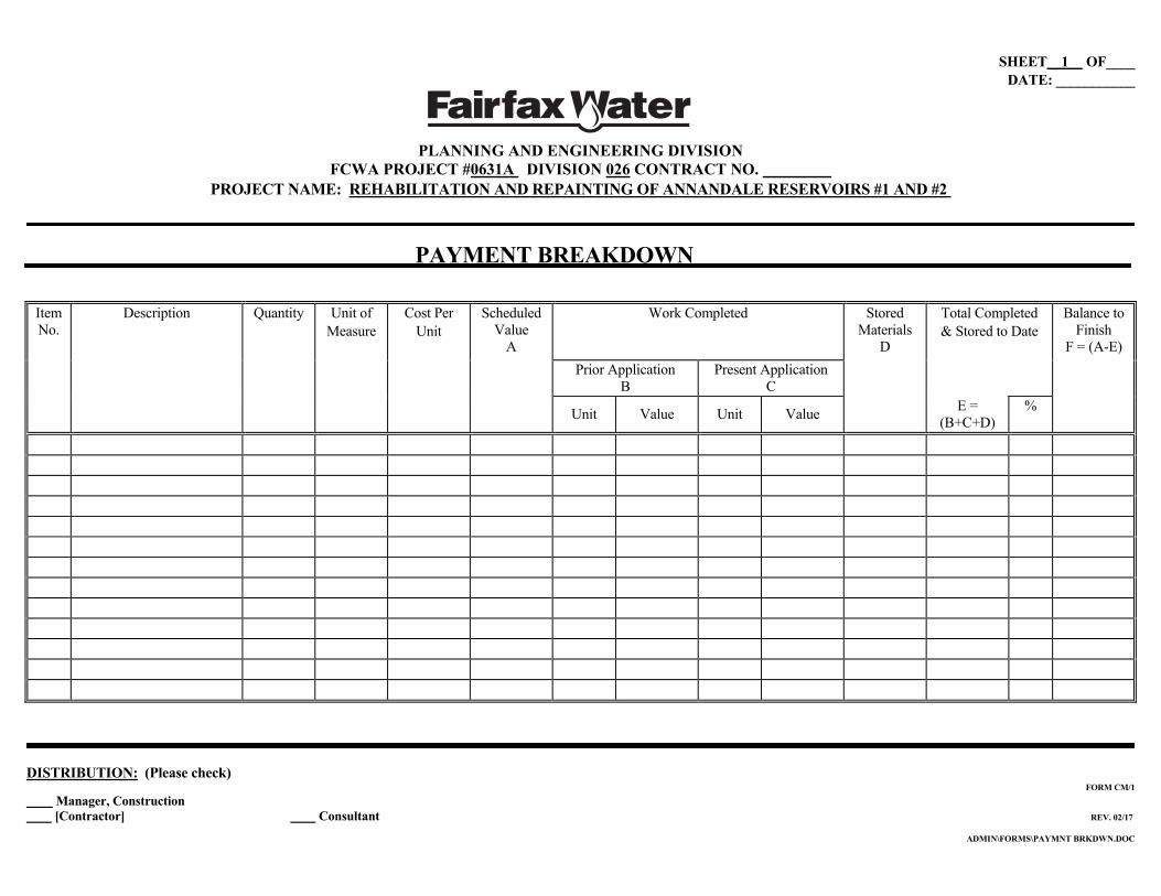
SHEET _ 1 OF____ DATE: ___________
PLANNING AND ENGINEERING DIVISION
FCWA PROJECT #0631A DIVISION 026 CONTRACT NO. PROJECT NAME: REHABILITATION AND REPAINTING OF ANNANDALE RESERVOIRS #1 AND #2
DISTRIBUTION: (Please check) FORM CM/1
Manager, Construction [Contractor] Consultant REV. 02/17
ADMIN\FORMS\PAYMNT BRKDWN.DOC
PAYMENT BREAKDOWN
Item No.
Description
Quantity Unit of Measure
Cost Per Unit
Scheduled Value
A
Work Completed Stored Materials
D
Total Completed & Stored to Date
Balance to Finish
F = (A-E) Prior Application
B Present Application
C
Unit Value Unit Value E = (B+C+D)
%
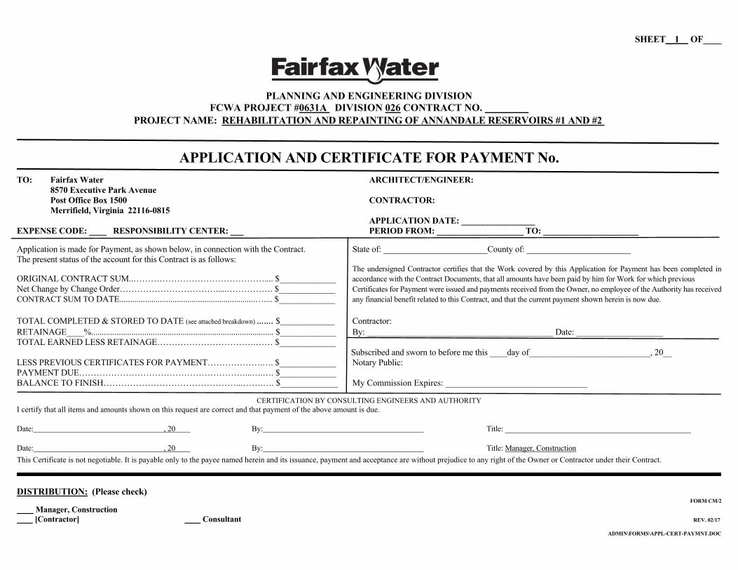
SHEET _ 1 OF____
PLANNING AND ENGINEERING DIVISION
FCWA PROJECT #0631A DIVISION 026 CONTRACT NO. PROJECT NAME: REHABILITATION AND REPAINTING OF ANNANDALE RESERVOIRS #1 AND #2
DISTRIBUTION: (Please check) FORM CM/2
Manager, Construction [Contractor] Consultant REV. 02/17
ADMIN\FORMS\APPL-CERT-PAYMNT.DOC
APPLICATION AND CERTIFICATE FOR PAYMENT No.
TO: Fairfax Water ARCHITECT/ENGINEER: 8570 Executive Park Avenue Post Office Box 1500 CONTRACTOR: Merrifield, Virginia 22116-0815 APPLICATION DATE: _________________ EXPENSE CODE: ____ RESPONSIBILITY CENTER: ___ PERIOD FROM: ____________________ TO: ______________________
Application is made for Payment, as shown below, in connection with the Contract. State of: ________________________County of: ________________________ The present status of the account for this Contract is as follows:
The undersigned Contractor certifies that the Work covered by this Application for Payment has been completed in ORIGINAL CONTRACT SUM..……………………………………….... $_____________ accordance with the Contract Documents, that all amounts have been paid by him for Work for which previous Net Change by Change Order…………………………….....……………. $_____________ Certificates for Payment were issued and payments received from the Owner, no employee of the Authority has received CONTRACT SUM TO DATE................................................................….... $_____________ any financial benefit related to this Contract, and that the current payment shown herein is now due. TOTAL COMPLETED & STORED TO DATE (see attached breakdown) ……. $________________ Contractor: RETAINAGE____%...................................................................................... $_____________ By: ___________________________________________ Date: ____________________ TOTAL EARNED LESS RETAINAGE…………………………….…… $_____________
Subscribed and sworn to before me this ____day of____________________________, 20__ LESS PREVIOUS CERTIFICATES FOR PAYMENT……………….…. $_____________ Notary Public: PAYMENT DUE…………………………………………………...….…. $_____________ BALANCE TO FINISH………………………………………...…….…. $_____________ My Commission Expires: ________________________________
CERTIFICATION BY CONSULTING ENGINEERS AND AUTHORITY
I certify that all items and amounts shown on this request are correct and that payment of the above amount is due. Date: , 20 By: Title: ________________________________________________
Date: , 20 By: Title: Manager, Construction This Certificate is not negotiable. It is payable only to the payee named herein and its issuance, payment and acceptance are without prejudice to any right of the Owner or Contractor under their Contract.

SHEET _ 2 OF____
PLANNING AND ENGINEERING DIVISION
FCWA PROJECT #0631A DIVISION 026 CONTRACT NO. PROJECT NAME: REHABILITATION AND REPAINTING OF ANNANDALE RESERVOIRS #1 AND #2
DISTRIBUTION: (Please check) FORM CM/2
Manager, Construction [Contractor] Consultant REV. 02/17
ADMIN\FORMS\APPL-CERT-PAYMNT.DOC
CONTRACTOR’S CERTIFICATION STATEMENT
CONTRACTOR: PAYMENT APPLICATION NO.:
The undersigned Contractor represents and certifies that to the best of his knowledge, information and belief that:
(1) All Work for which this Application for Payment is submitted has been completed in full and in accordance with the Contract Documents;
(2) The only outstanding and due items for payment (by the Owner) with respect to the Contract are those to be paid from the funds for which Application is being made;
(3) Title to all Work, stored materials and equipment covered by this Application for Payment will pass to the Owner either upon incorporation in the construction or upon receipt of payment by the Contractor, whichever occurs first, free and clear of all liens, claims, security interests or encumbrances; and no Work, materials or equipment covered by this Application for Payment will have been acquired by the Contractor or by any other person performing the Work at the site or furnishing materials and equipment for the Project, subject to an agreement under which an interest therein or an encumbrance thereon is retained by the seller or otherwise imposed by the Contractor or such other person;
(4) All materials stored on-site or at any other location, for which payment is requested by this Application, have been properly stored and protected as required by the Contract Documents;
(5) No employee of the Authority has received any financial benefit related to this Contract;
(6) That the current payment shown herein is now due; and
(7) Due and payable amounts and bills have been paid by the Contractor for work for which previous Certificates of Payment were issued and payments received from the Owner; and all Subcontractors or suppliers have been fully and timely paid, except for retainage per the subcontract, for all work performed prior to the time encompassed within this Application for Payment, except for the following (please state Subcontractor name, amount outstanding and reason for nonpayment; if there is no exception, please write none in the following blank):
By: Date:
State of ) County of ) to wit: On the day of , 20 before me
personally came and appeared to me known, who by me duly sworn, did depose and say that he is the of the that he has the authority to bind the above named
firm; and he represents and certifies the foregoing statements are true and complete to the best of his knowledge, information and belief.
My Commission Expires: By: (Seal)

PLANNING AND ENGINEERING DIVISION
FCWA PROJECT #0631A DIVISION 026 CONTRACT NO. PROJECT NAME: REHABILITATION AND REPAINTING OF ANNANDALE RESERVOIRS #1 AND #2
DISTRIBUTION: (Please check) FORM CM/4
Manager, Construction [Contractor] Consultant REV. 02/17
REQUEST FOR CLARIFICATION NO. ____ Transmitted To: Date: Requested By: Drawings No: Spec Section: Questions: (Provide complete description of request with sketches or photos if necessary. Present status of work and suggest a solution, if any) Response: By: (Printed Name and Signature) Date:

Rev 1/16
Planning and Engineering Division PROPOSED CHANGE ORDER PROJECT: REHABILITATION AND REPAINTING OF ANNANDALE RESERVOIRS #1 AND #2 PCO NO.: _ DATE: FROM: CONTRACT NO.: PROJECT NO.: 0631A , Division 026 TO: FAIRFAX WATER REFERENCES: CONTRACTOR hereby submits this request for a change in the Contract Sum and/or the Contract Period to perform all Work associated with the above-referenced Work Order or to perform or delete Work in response to the above-referenced Request for Change Order Proposal as follows:
(1) The total direct and indirect costs, with applicable mark-ups for the performance of the proposed change in the work is as follows:
$ (Detailed Breakdown Attached)
(2) The increase in the Contract period or extensions of Contract Milestone Dates requested for this proposed Change, supported by the scheduling analysis required by the Contract Documents for such requested time extensions, is as follows:
Calendar Days - Contract Period (Details Attached)
Calendar Days - Milestone: ___________________________________
The Contractor understands and certifies that the proposal stated herein represents all estimated direct and indirect costs and applicable mark-ups allowed by the Contract Documents and/or additional time of performance of the Work associated with this proposed Change. The Contractor further certifies that to the best of his knowledge and belief the cost and pricing data and scheduling analysis submitted herein regarding the performance of the proposed Change in the Work or the deletion of a part of the Work is complete, accurate and current. The Contractor will perform the proposed Change in the Work as directed by the Owner or Engineer.
CONTRACTOR: _____________________________________
BY: _______________________________________________
DATE: _____________________________________________

SHEET 1 OF 4_
PLANNING AND ENGINEERING DIVISION FCWA PROJECT #0631A DIVISION 026 CONTRACT NO.
PROJECT NAME: REHABILITATION AND REPAINTING OF ANNANDALE RESERVOIRS #1 AND #2
SUBCONTRACTOR QUALIFICATION FORM
The Contractor must provide all information requested herein with respect to each
proposed subcontractor. Duplicates of this form may be used in order to supply the requested information with respect to each such proposed subcontractor. Any doubt on the part of the Contractor with respect to the necessity of disclosing information shall be resolved in favor of disclosure.
Please type or print clearly in black ink. The Contractor may attach additional pages if
necessary, and should number any such additional pages consecutively, referencing applicable sections of this form.
PROPRIETARY INFORMATION
The Contractor, at the request of the Proposed Subcontractor, may elect to designate all
information contained in this Subcontractor Qualification Form as proprietary by checking the appropriate box.
☐ The information contained in this Subcontractor Qualification Form is submitted
voluntarily and deemed a trade secret or proprietary information pursuant to §11-52 of the Code of Virginia, as amended.
☐ The information contained in this Subcontractor Qualification Form is submitted
voluntarily and is not considered a trade secret or proprietary information.
Subcontractor Name:
Subcontractor’s Trade or Specialty:
Street Address:
City, State, Zip Code:
Telephone No. Fax No. E-Mail: Primary contact with the firm:
Name: Title: Telephone:

SHEET 2 OF 4_
Type of Firm:
☐ Corporation (if a corporation, provide date and state of incorporation in space below)
☐ Partnership (if a partnership, provide names of all partners, general and limited, and state of organization, as well as date of formation of partnership in space below)
☐ Individual Owner (if individual owner, provide name of owner and date of
commencement of business in space below)
☐ Joint Venture (if joint venture, provide information for each party to venture and date of formation of joint venture in space below)
☐ Limited Liability Company (if limited liability company, provide names for all
members as well as state of organization in space below)
Federal Employer Identification Number:
Virginia Contractor’s License Number dated . (If the Subcontractor does not currently hold a Virginia Contractor’s License, provide a detailed description of how the Subcontractor will obtain a license prior to its commencement of any Work ((as such term is defined in the Contract Documents.))
In the spaces set forth below, please provide the information requested with regard to three contracts performed by the Subcontractor within the past 4 months which were similar in nature and scope to that proposed to be performed on behalf of the Contractor for the above-referenced Project.
1. (a) Project identification and location:
(b) Names, title, addresses and phone numbers of the owner and the general contractor:
Owner: Address: Telephone: Individual to Contact and Title:

SHEET 3 OF 4_
General Contractor: Address: Telephone: Individual to Contact and Title:
(c) Description of specific work performed:
(d) Subcontract price:
Original subcontract value: Final subcontract value:
2. (a) Project identification and location:
(b) Names, titles, addresses and phone numbers of owner and general contractor:
Owner: Address: Telephone: Individual to contact and title:
General Contractor: Address: Telephone: Individual to contact and title:
(c) Description of specific work performed:

SHEET 4 OF 4_
DISTRIBUTION: (Please check) FORM CM/12
Manager, Construction Other
Rev. 01/07ADMIN\FORMS\SUBCON QUALIF.DOC
(d) Subcontract price:
Original subcontract value: Final subcontract value:
3. (a) Project identification and location:
(b) Names, titles, addresses and phone numbers of owner and general contractor:
Owner: Address: Telephone: Individual to contact and title:
General Contractor: Address: Telephone: Individual to contact and title:
(c) Description of specific work performed:
(d) Subcontract price:
Original subcontract value: Final subcontract value:

PLANNING AND ENGINEERING DIVISION FCWA PROJECT #0631A DIVISION 026 CONTRACT NO.
PROJECT NAME: REHABILITATION AND REPAINTING OF ANNANDALE RESERVOIRS #1 AND #2
Pre-Approved Contractor Form Prepared By: Date Submitted: The purpose of this form is to provide a common basis of informing Fairfax Water Security Guards of Contractors who routinely visit the Treatment Plant. Individuals and representatives of companies named on this form have been pre-approved for plant access by the department completing this form and do not need to have access verified at the time of arrival.
Department Name Date of Submission
Department Contact
Telephone No.
Name of Company Company Contact Telephone No. Name of Representative
Allowed Access Type of Work Dates of Access Hours of Access
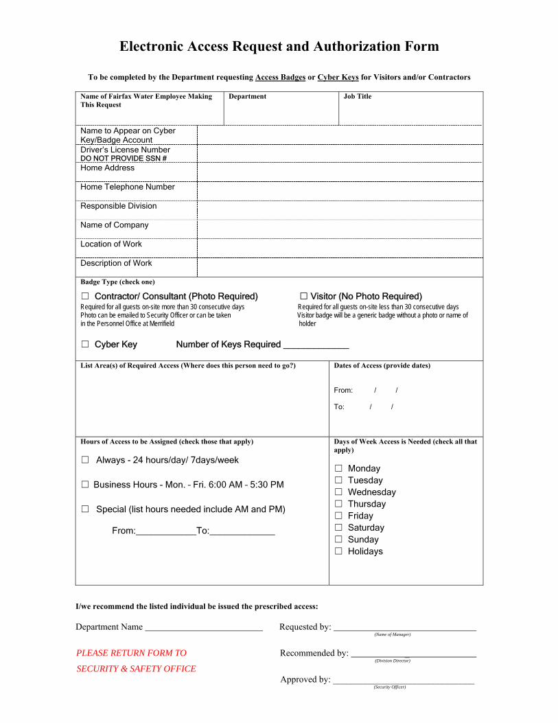
Electronic Access Request and Authorization Form
To be completed by the Department requesting Access Badges or Cyber Keys for Visitors and/or Contractors
I/we recommend the listed individual be issued the prescribed access:
Department Name Requested by:
(Name of Manager)
PLEASE RETURN FORM TO Recommended by: _ (Division Director)
SECURITY & SAFETY OFFICE Approved by: _______________________________ (Security Officer)
Name of Fairfax Water Employee Making This Request
Department Job Title
Name to Appear on Cyber Key/Badge Account
Driver’s License Number DO NOT PROVIDE SSN #
Home Address
Home Telephone Number
Responsible Division
Name of Company
Location of Work
Description of Work
Badge Type (check one)
☐ Contractor/ Consultant (Photo Required) □ Visitor (No Photo Required) Required for all guests on-site more than 30 consecutive days Required for all guests on-site less than 30 consecutive days Photo can be emailed to Security Officer or can be taken Visitor badge will be a generic badge without a photo or name of in the Personnel Office at Merrifield holder ☐ Cyber Key Number of Keys Required _____________ List Area(s) of Required Access (Where does this person need to go?)
Dates of Access (provide dates)
From: / / To: / /
Hours of Access to be Assigned (check those that apply) ☐ Always - 24 hours/day/ 7days/week
☐ Business Hours - Mon. – Fri. 6:00 AM – 5:30 PM
☐ Special (list hours needed include AM and PM) From:____________To:_____________
Days of Week Access is Needed (check all that apply) ☐ Monday ☐ Tuesday ☐ Wednesday ☐ Thursday ☐ Friday ☐ Saturday ☐ Sunday ☐ Holidays

SHEET 1 OF _
DATE: _
PLANNING AND ENGINEERING DIVISION
FCWA PROJECT #0631A DIVISION 026 CONTRACT NO. PROJECT NAME: REHABILITATION AND REPAINTING OF ANNANDALE RESERVOIRS #1 AND #2
DISTRIBUTION: (Please check) Manager, Construction [Contractor] Consultant REV. 02/17
CONTRACTOR’S NOTICE OF BENEFICIAL USE
DATE OF ISSUANCE: ___________________________ CONTRACT DATE: _____________________________ WORK OR DESIGNATED PORTION OF WORK SHALL INCLUDE: ____________________________________ _______________________________________________________________________________________________
Work performed under this Contract has been thoroughly inspected and is considered to be sufficiently complete, in accordance with Contract Documents, so Owner can occupy or utilize Work or designated portion thereof for its intended use.
☐ Certificates of inspections indicating compliance with requirements of governing authorities are attached hereto. ☐ Certificate of Occupancy have been obtained from governing authorities, are attached hereto. ☐ A comprehensive list of items to be completed or corrected, prepared by Contractor is attached, hereto. Failure to include
any items on such list does not alter responsibility of Contractor to complete all Work in accordance with Contract Documents.
Contractor will complete or correct Work by: ________________________ CONTRACTOR BY DATE
OWNER (agrees) (does not agree) to accept portions designated above separately from the rest of the Project. Owner intends to utilize, occupy or take use on: _________________________________________________________ FAIRFAX WATER MANAGER, CONSTRUCTION DATE
The Work designated above, has been determined to be: ☐ Sufficiently complete and a Certificate of Beneficial Use will be issued.
☐ Not complete for the following reasons: _______________________________________________________ ______________________________________________________________________________________ ______________________________________________________________________________________ CONSULTANT BY DATE
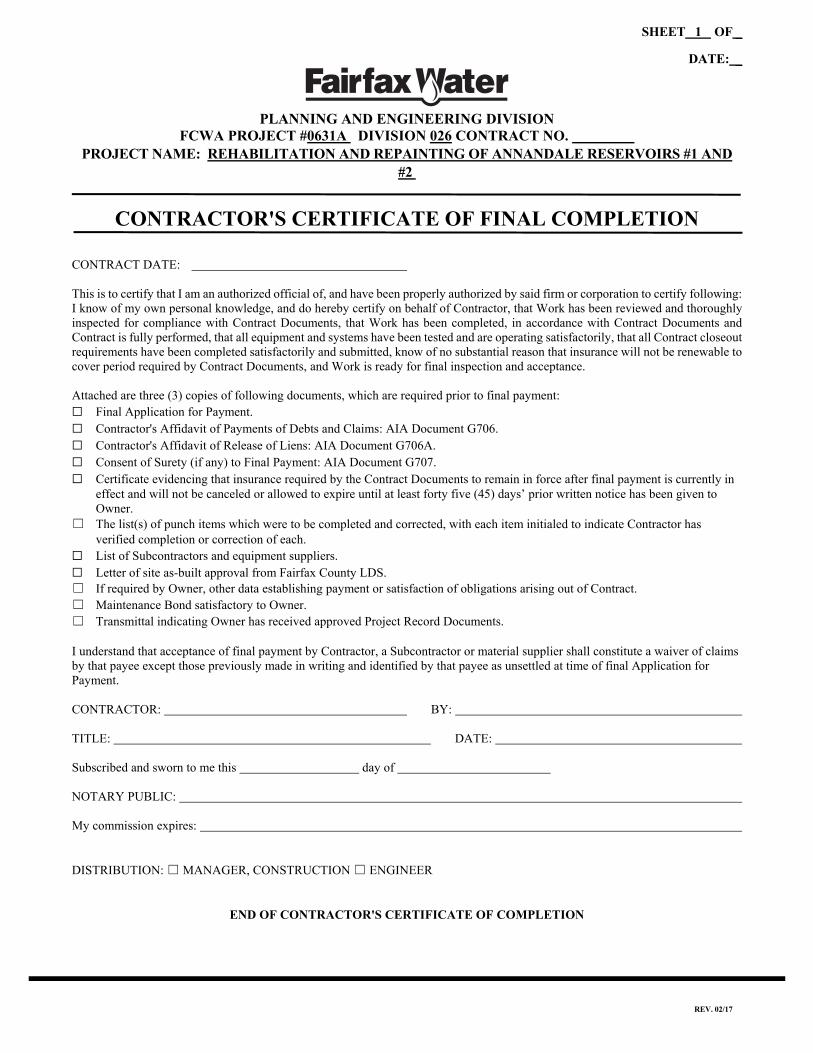
SHEET 1 OF _
DATE: _
PLANNING AND ENGINEERING DIVISION
FCWA PROJECT #0631A DIVISION 026 CONTRACT NO. PROJECT NAME: REHABILITATION AND REPAINTING OF ANNANDALE RESERVOIRS #1 AND
#2
REV. 02/17
CONTRACTOR'S CERTIFICATE OF FINAL COMPLETION
CONTRACT DATE: This is to certify that I am an authorized official of, and have been properly authorized by said firm or corporation to certify following: I know of my own personal knowledge, and do hereby certify on behalf of Contractor, that Work has been reviewed and thoroughly inspected for compliance with Contract Documents, that Work has been completed, in accordance with Contract Documents and Contract is fully performed, that all equipment and systems have been tested and are operating satisfactorily, that all Contract closeout requirements have been completed satisfactorily and submitted, know of no substantial reason that insurance will not be renewable to cover period required by Contract Documents, and Work is ready for final inspection and acceptance. Attached are three (3) copies of following documents, which are required prior to final payment: ☐ Final Application for Payment. ☐ Contractor's Affidavit of Payments of Debts and Claims: AIA Document G706. ☐ Contractor's Affidavit of Release of Liens: AIA Document G706A. ☐ Consent of Surety (if any) to Final Payment: AIA Document G707. ☐ Certificate evidencing that insurance required by the Contract Documents to remain in force after final payment is currently in
effect and will not be canceled or allowed to expire until at least forty five (45) days’ prior written notice has been given to Owner.
☐ The list(s) of punch items which were to be completed and corrected, with each item initialed to indicate Contractor has verified completion or correction of each.
☐ List of Subcontractors and equipment suppliers. ☐ Letter of site as-built approval from Fairfax County LDS. ☐ If required by Owner, other data establishing payment or satisfaction of obligations arising out of Contract. ☐ Maintenance Bond satisfactory to Owner. ☐ Transmittal indicating Owner has received approved Project Record Documents. I understand that acceptance of final payment by Contractor, a Subcontractor or material supplier shall constitute a waiver of claims by that payee except those previously made in writing and identified by that payee as unsettled at time of final Application for Payment. CONTRACTOR: BY: TITLE: DATE: Subscribed and sworn to me this day of NOTARY PUBLIC: My commission expires: DISTRIBUTION: ☐ MANAGER, CONSTRUCTION ☐ ENGINEER
END OF CONTRACTOR'S CERTIFICATE OF COMPLETION

SHEET 1 OF 2
DATE: _
PLANNING AND ENGINEERING DIVISION
FCWA PROJECT #0631A DIVISION 026 CONTRACT NO. PROJECT NAME: REHABILITATION AND REPAINTING OF ANNANDALE RESERVOIRS #1 AND #2
REV. 02/17
CONSENT OF SURETY COMPANY TO FINAL PAYMENT TO: CONTRACTOR: Fairfax County Water Authority (d/b/a: Fairfax Water) 8560 Arlington Blvd. Fairfax, Virginia 22031 CONTRACT DATE:
In accordance with Article 10.5 of the General Conditions of the Contract between Fairfax Water and the Contractor referenced above, the
SURETY COMPANY, On bond of , CONTRACTOR, hereby approves of the final payment to the Contractor, and agrees that no payment, however, final or otherwise, shall operate to release the Contractor or the SURETY COMPANY from any obligations to Fairfax Water under this Contract or the Performance and Payment Bonds.
(SIGNATURES ON FOLLOWING PAGE)

SHEET 2 OF 2
REV. 02/17
IN WITNESS WHEREOF, The Surety Company has hereunto set its hand this day of , Surety Company Signature of Authorized Representative Attest: (Seal) Title

SHEET 1 OF 2
PLANNING AND ENGINEERING DIVISION FCWA PROJECT #0631A DIVISION 026 CONTRACT NO.
PROJECT NAME: REHABILITATION AND REPAINTING OF ANNANDALE RESERVOIRS #1 AND #2
FORM CM/11 REV. 02/17
ADMIN\FORMS\PAYMNT AFFID-RELEASE.DOC
FINAL PAYMENT AFFIDAVIT AND RELEASE OF CLAIMS TO: Fairfax County Water Authority (d/b/a: Fairfax Water) 8560 Arlington Blvd. Fairfax, Virginia 22031 FROM: (the “Contractor”) Contract Between Fairfax Water and the Contractor dated (the “Contract”) for the aforementioned project (the Project and real property upon which it is situated are collectively referred to herein as the “Property”) The Contractor hereby (1) acknowledges receipt of all but $ , monies being withheld pending release of claims for all labor, materials, services and benefits (collectively, the “Work”) provided pursuant to, and any other amounts due under, the Contract; (2) waives and releases any and all mechanics’, materialman’s and like liens, and all rights to file any such liens, against the Property for any or all of the Work provided by the Contractor pursuant to the Contract (regardless of whether any such lien properly may be filed against Fairfax Water’s Property); (3) agrees to pay and release of record promptly all mechanics’, materialman’s and like liens filed by itself or others in connection with the Work provided under the Contract which may now or in the future affect the Property; (4) represents and warrants that the Contractor has fully paid all laborers, materialmen and subcontractors of the Contractor for all Work provided by them in connection with the Contract; (5) represents that neither the Contractor nor any other person with whom the Contractor has dealt has any right to file a mechanic’s, materialman’s or like lien against the Property or has any other claims of any nature (whether pending or threatened) on account of any Work provided by or through the Contractor; (6) waives and releases any and all actions, debts, claims and demands against Fairfax Water arising from or in connection with the Work provided by or through the Contractor pursuant to the Contract Documents; and (7) agrees to defend, indemnify and hold harmless Fairfax Water from any and all loss, cost, liability or claim (including, without limitation, court costs and attorneys’ fees) arising out of: (a) any misrepresentation or breach of any of the foregoing representations, covenants and warranties, or (b) the filing or enforcement of any lien or claim of lien or any other claim by the Contractor or by any laborer, materialman or subcontractor of the Contractor or in connection with the Work covered by the Contract.

SHEET 2 OF 2
Dated: [Insert name of Contractor as it appears on the Contract] By: [Signature of officer or authorized agent signing for Contractor] Name: [Print name of person signing] Title: [Print title of person signing] STATE OF ) CITY/COUNTY OF ) SUBSCRIBED AND SWORN TO before me in the above jurisdiction this day of , , by the person whose name appears above. My commission expires: . [Notarial Seal] Notary Public _______________________________________________

Project 0631A Division 026 01290-1 10/23/2020
SECTION 01290
APPLICATIONS FOR PAYMENT
PART 1 GENERAL 1.01 SCOPE OF WORK
A. Submit Applications for Payment to the Engineer and Owner in accordance with the terms and schedule established by the General Conditions of the Contract and Agreement between Owner and Contractor.
B. The accepted Schedule of Values (defined under Section 01330) shall be used as the basis for the Contractor’s Application for Payment.
1.02 RELATED WORK
A. Section 00500: Agreement between Owner and Contractor.
B. Section 00700: General Conditions.
C. Section 01250: Contract Modification Procedures.
D. Section 01320: Construction Schedule.
E. Section 01770: Contract Closeout.
1.03 FORMAT AND DATA REQUIRED
A. Submit applications in automated format using the Application for Payment form provided by the Owner (under Exhibits to the General Conditions). Each submittal shall be accompanied by a Compact Disk containing a spreadsheet set up in the same format as the Schedule of Values (Section 01330) providing complete documentation of all items for which payment is requested. Text and tabular data shall be in Microsoft Excel latest version for Windows format. No payment will be made until the Schedule of Values is approved.
B. Provide construction photographs in accordance with Section 01330.
C. Monthly updated progress schedule, employee identification logs, and submittal of required O&M manuals will be a prerequisite to payment.
1.04 PREPARATION OF APPLICATION FOR PROGRESS PAYMENT
A. Application Form:
1. Fill in required information, including that for Change Orders executed prior to date of submittal of application.
2. Fill in summary of dollar values to agree with respective totals indicated on continuation sheets.
3. Execute certification with signature of a responsible officer of Contract firm. An original notarized signature shall appear on each copy submitted.

Project 0631A Division 026 01290-2 10/23/2020
B. Continuation Sheets:
1. Fill in total list of all scheduled component items of Work with item number and scheduled dollar value for each item.
2. Fill in dollar value in each column for each scheduled line item when work has been performed or products stored.
a. Round off values to nearest dollar, or as specified for Schedule of Values.
3. List each Change Order executed prior to date of submission at the end of the continuation sheets. List by Change Order Number, and description, as for an original component item of work.
4. To receive approval for payment on component material stored on site, submit certified true copies of the original paid invoices with the application for payment first made for these materials. Refer to Article 10, Section 00700 for payment on stored materials.
1.05 SUBSTANTIATING DATA FOR PROGRESS PAYMENTS
A. When requested, submit substantiating information with a cover letter identifying:
1. Project.
2. Application number and date.
3. Detailed list of enclosures.
4. For stored products:
a. Item number and identification as shown on application.
b. Description of specific material.
B. Submit one copy of data and cover letter for each copy of application.
C. Maintain an updated set of drawings to be used as record drawings. As a prerequisite for monthly progress payments, exhibit the updated record drawings for review by Owner and Engineer.
D. The Contractor shall maintain an updated construction schedule in accordance with Section 01320. As a prerequisite for monthly progress payments, contractor shall submit the updated construction schedule with the application for progress payments. If the Contractor fails to submit the required updated schedule within the time prescribed, the Engineer may withhold approval of progress payment estimates until such time as the Contractor submits the required updated schedule. Submit as required under Section 01320.
E. The Contractor shall demonstrate, as a prerequisite for monthly progress payments, compliance with all requirements specified in Section 02370 to the Engineer. If the Contractor fails to demonstrate compliance with Section 02370, the Engineer may withhold approval of progress payment estimates until such time as the Contractor demonstrates to the Engineer full compliance with the approved erosion and sedimentation control permit and Section 02370.
F. The Contractor shall provide, as a prerequisite for monthly progress payments, an accumulating
cost curve (tabular and diagram), indicating schedule, forecast and actual progress.
G. The Contractor shall provide employee identification logs as required under Section 01500 as a prerequisite for monthly progress payments.

Project 0631A Division 026 01290-3 10/23/2020
1.06 PREPARATION OF APPLICATION FOR FINAL PAYMENT
A. Fill in Application form as specified for progress payments.
B. Use continuation sheet for presenting the final statement of accounting as specified in Section 01770 – Contract Closeout.
C. Submit all Project Records Documents in accordance with Sections 01770.
D. Satisfy all other final completion and contract close-out requirements. 1.07 SUBMITTAL PROCEDURES
A. Submit Applications for Payment to the Engineer or Owner at the times stipulated in the Agreement.
B. Number: Three copies of each Application
C. When Application is found to be properly completed and corrected, three originals will be transmitted to Owner and one copy will be returned to Contractor.
PART 2 PRODUCTS
Not Used
PART 3 EXECUTION Not Used
END OF SECTION

Project 0631A Division 026 01310-1 10/23/2020
SECTION 01310
PROJECT MEETINGS
PART 1 GENERAL
1.01 SECTION INCLUDES
A. Preconstruction Conference
B. Progress Meetings
C. Pre-Installation and Pre-Demolition Conferences
1.02 PRECONSTRUCTION MEETINGS
A. General: Prior to the commencement of Work at the Site, a minimum of two preconstruction meeting(s) will be required.
1. Preconstruction Conference: Prior to the commencement of Work at the Site, a preconstruction conference will be held at a predetermined time and place.
B. Preconstruction Conference:
1. Attendance: The conference shall be attended by the following:
a. The Contractor and his Superintendent b. The principal Subcontractors c. The representatives of principal suppliers and manufacturers as appropriate d. The Engineer and his resident project representative(s) e. The Authorized Representatives of the Owner f. Governmental representatives as appropriate g. Others, as requested by the Contractor, the Owner, or the Engineer 2. Purpose: The purpose of the conference is to designate responsible personnel and
establish a working relationship. Matters requiring coordination will be discussed, and procedures for handling such matters, established. The agenda will include the following items:
a. Transmittal, review, and distribution of Contractor's submittals b. Processing applications for payment c. Maintaining record documents d. Critical work sequencing e. Field decisions, Change Orders and Work Orders
Project 0631A Division 026 01310-2 10/23/2020
f. Use of premises, office and storage areas, security, housekeeping, and the Owner's
needs g. Major equipment deliveries and priorities h. Contractor's assignments for safety and first aid
2. Meeting Chairman: The Engineer will preside at the conference and will arrange for keeping the minutes and distributing the minutes to all persons in attendance.
C. Preconstruction Survey: Before any Work is performed at the site by the Contractor, a joint
preconstruction survey will be performed. The Contractor, Engineer and Owner will review the existing conditions jointly and record via video and digital photos this review. The Contractor shall be responsible for procuring the services of a professional photographer and for scheduling the preconstruction survey; however, the survey date(s) shall be coordinated with the Owner. When the survey is completed, the Owner shall be provided with the original CD/DVD and photographs. Following completion of the Work, the video and photographs may be used to compare conditions prior to construction to those conditions following construction to ascertain that the Site has been properly restored.
1.03 PROGRESS MEETINGS
A. Purpose: The purpose of the meetings will be to review the progress of the Work, maintain coordination of efforts, discuss changes in scheduling, review safety and quality control activities, and resolve other potential problems.
B. Scheduling: The Owner and the Contractor will schedule and hold regular progress meetings at least monthly and at other times as requested by the Engineer or required by progress of the Work. The Contractor, the Engineer, and all subcontractors active on the site shall be represented at each meeting. The Contractor may, at his discretion, request attendance by representatives of his suppliers, manufacturers, and other subcontractors.
C. Meeting Chairman: The Engineer shall preside at the meetings and provide for keeping and distributing the minutes.
1.04 PRE-INSTALLATION AND PRE-DEMOLITION CONFERENCES
A. Conduct conferences at the Project site before the start of each construction activity as specified in the Specifications or otherwise directed by the Owner.
B. Attendees: Subcontractors, installers and representatives of manufacturers involved with or
affected by the installations shall attend the meeting. The Contractor shall advise the Owner/Engineer of scheduled meeting dates.
C. Agenda: Review progress of construction activities and preparations for the particular activity,
including requirements for the following:
1. The applicable contract document requirements. 2. Related RFCs / Change Orders 3. Purchases / Deliveries 4. Submittals / Review of mockups 5. Possible conflicts (space, access, compatibility issues) 6. Time schedules 7. Temporary facilities and controls 8. Inspections/Quality control 9. Safety (Protection of construction, equipment, and personnel)

Project 0631A Division 026 01310-3 10/23/2020
10. Installation procedure(s) 11. Coordination with other work
D. The Contractor is to keep a written record of each meeting and produce/distribute minutes
recording discussions and agreements for items above to all attendees.
PART 2 PRODUCTS
Not Used
PART 3 EXECUTION
Not Used
END OF SECTION 01310

Project 0631A Division 026 01320-1 10/23/2020
SECTION 01320
CONSTRUCTION SCHEDULE PART 1 - GENERAL 1.01 DESCRIPTION OF REQUIREMENTS
A. This Section specifies the general methods and requirements of submissions applicable to the Construction Progress Schedule. Detailed submittal requirements are specified in the technical sections.
1.02 CONSTRUCTION PROGRESS SCHEDULE
A. Submit the baseline schedule, reflecting major tasks and subtasks, within 20 calendar days
of Notice to Proceed.
B. Work shall be scheduled using the Critical Path Method (CPM) type of network analysis. The schedule should be developed and maintained using MS Project, latest Windows version or an approved equal.
C. The Critical Path Method type construction schedule will be used to monitor job progress.
The Contractor shall be responsible for providing all information concerning the sequencing, logic and duration of all activities as well as providing the initial CPM logic network (in electronic and paper form) diagram Gantt Chart and tabular report data. Once the baseline schedule is accepted by the Engineer and the Owner, the Contractor shall be responsible for providing monthly updates of the CPM schedule showing actual progress. The Contractor shall submit the computerized printout of the schedule and highlight major changes, if any, on a monthly basis. Within the first week of each month, three (3) copies of the updated schedules shall be submitted to the Owner. If requested by Owner, within the first week of each month, one CD with the electronic file of the updated schedules shall be submitted to the Owner.
D. The contractor shall provide 3-week look-ahead reports at each Monthly Progress meeting
as specified in Section 01310.
E. The schedule shall show fabrication and delivery times for all major equipment items.
F. The schedule must include all required start-up and commissioning activities.
G. The Contractor shall submit a complete separate and independent schedule and detailed listing of anticipated submittals during the Contract Period. The submittal schedule shall be submitted within 30 days after Notice to Proceed. The submittal schedule shall then be accepted or revised as required by the Engineer and the Owner within 14 days after receipt, and the Contractor shall incorporate the dates and review durations into his complete CPM schedule.
H. A CPM schedule which shows a completion of any milestone or completion dates prior to the contractual completion date for that milestone or completion date may be accepted, but in no event shall be acceptable as a basis for a claim for additional cost, delay or acceleration against the Owner and Engineer and any of their authorized representatives if the early completion date is not met by the Contractor.
I. Schedule Revisions. The Contractor shall submit any proposed revisions to the accepted
baseline CPM schedule to the Owner for review and acceptance. CPM revisions shall be submitted as a computerized printout of the schedule, three (3) copies, and if requested one CD with the electronic file. All proposed revisions to activities, logic, activity durations,

Project 0631A Division 026 01320-2 10/23/2020
and critical path shall be justified in written tabular form and shall include the impact of the proposed schedule revisions on the project. The Contractor shall not make any changes in the accepted baseline CPM schedule without the prior written acceptance of the Owner and Engineer.
J. Float
1. Definition of Float. As employed in the Contract Documents, the terms “float” and “float time” shall be used interchangeably to mean the period of time between the early start date and the late start date, or the early finish date and the late finish date of any activities set forth on the Construction Schedule.
2. Ownership of Float. The Owner shall have and retain exclusive ownership of the float.
3. Float Time. The Contractor shall not be entitled to any adjustment in the Contract Period, the Construction Schedule, or the Contract Sum, or to any additional payment of any sort by reason of the loss or use of any float time. The Owner may initiate changes to the Work that absorb float time without obligation to adjust or extend the overall completion date or any intermediate completion dates set forth in the CPM network. Owner-initiated changes that affect the critical path on the CPM network shall be the sole grounds for extending (or shortening) the Contract Period. Contractor-initiated changes that encroach on the float time identified in the CPM network may be accomplished with the Owner’s prior approval. Such changes, however, shall give way to Owner-initiated changes competing for the same float time. Delays in the critical path that are not associated with proper requests for time extensions in accordance with Article 8 of the General Conditions shall be deemed to be the responsibility of the Contractor.
K. Delays to Critical Path
1. Whenever it becomes apparent from the current monthly CPM schedule update that delays to the critical path have resulted and these delays are through no fault of the Owner or Engineer and hence, that the Contract completion date will not be met, or when so directed by the Engineer, the Contractor shall take some or all of the following actions at no additional cost to the Owner.
a. Increase construction manpower in such quantities and crafts as will
substantially eliminate the backlog of Work.
b. Increase the number of working hours per shift, shifts per day, or working days per week; the amount of construction equipment; the forms for concrete work; etc., or any combination of the foregoing to substantially eliminate the backlog of Work.
c. Reschedule activities to achieve maximum practical concurrence of
accomplishment of activities, and comply with the revised schedule.
d. The Contractor shall submit to the Owner and Engineer for review a written statement of the steps he intends to take to remove or arrest the delay to the schedule. The Contractor shall promptly provide such level of effort to bring the Work back on schedule. Should schedule delays persist, the Contractor's Surety may be asked to attend schedule update meetings.

Project 0631A Division 026 01320-3 10/23/2020
2. Failure of the Contractor to comply with the requirements herein shall subject him to, at the Owner's sole discretion, withholding, in partial or in total, payments otherwise due the Contractor for work performed under the Contract. Any withholding of monies is not a penalty for noncompliance, but is an assurance for the Owner that funds will be available to implement these requirements should the Contractor fail to do so, since failure of the Contractor to comply with these requirements shall mean that the Contractor failed to prosecute the Work with such diligence as to ensure its completion within the contractual dates.
L. The Contractor will not be entitled to any extension of time for the completion of the
Project, nor to recover any damages for any delay attributed to the Owner, the Engineer, or their agents, with respect to any delay that is alleged to have occurred during a period of time in which the Contractor has failed to provide or to maintain an approved accepted schedule that meets all requirements of the Contract Documents.
PART 2 - PRODUCTS (NOT USED) PART 3 - EXECUTION (NOT USED)
- END OF SECTION –

Project 0631A Division 026 01330-1 10/23/2020
SECTION 01330
SUBMITTALS
PART 1 GENERAL
1.01 DESCRIPTION OF REQUIREMENTS
A. This Section specifies the general methods and requirements of submissions applicable to Shop Drawings, Product Data, Samples, Mock Ups, Construction Photographs, and Submittal Schedules. Detailed submittal requirements are specified in the technical sections.
B. All submittals shall be clearly identified by reference to Section Number, Paragraph,
Drawing Number or Detail as applicable. Submittals shall be clear and legible and of sufficient size for presentation of data.
1.02 CONSTRUCTION PROGRESS SCHEDULE
A. Contractor shall submit to Engineer for review a schedule of the proposed construction
operations in accordance with Section 01320.
B. At least monthly the schedule shall be revised and resubmitted as necessary to reflect changes in the progress of the Work.
C. Owner may require Contractor, at Contractor's expense, to add to its plant, equipment, or
construction forces, as well as increase the working hours, if operations fall behind schedule at any time during the construction period.
D. If the initial progress schedule or any subsequent revision is not acceptable to Engineer,
the schedule shall be revised and resubmitted as many times as necessary until the schedule is acceptable.
1.03 SHOP DRAWING SUBMITTAL SCHEDULE
A. Contractor shall submit to Engineer a schedule of submittals for the Shop Drawings and
Engineering Data that are required by the specifications in accordance with Section 01320.
1.04 PROGRESS REPORTS
A. A progress report shall be submitted to Engineer each month with the application for
partial payment. If the Work falls behind schedule, Contractor shall submit additional progress reports at such intervals as Engineer may request.
B. Each progress report shall include sufficient narrative to describe current and anticipated
delaying factors, their effect on the progress schedule, and proposed corrective actions. Any Work reported complete, but which is not readily apparent to Engineer, must be substantiated with satisfactory evidence.
C. Each progress report shall also include three copies of the accepted graphic schedule
updated to indicate actual progress.

Project 0631A Division 026 01330-2 10/23/2020
1.05 SCHEDULE OF VALUES
A. Schedule of Values shall be submitted to Owner and Engineer for review within 20 days of the Notice To Proceed.
B. The Contractor shall prepare a bid breakdown for the Lump Sum Contract Items in
accordance with Article 10B of the General Conditions. The bid breakdown shall be prepared in such manner as approved by the Engineer to permit apportionment of construction cost to the various facilities, equipment, and structures included in this Contract.
C. The lump sum bid shall be broken down by reference to the applicable Specification
Sections.
D. In addition to the dollar amount for each item, the bid breakdown shall include the physical quantities of the Work required for each item. Quantities listed shall be in units of number, size, length, area, volume or weight which are customarily used and can be readily verified.
E. Equipment items requiring appreciable amounts of installation effort shall be broken down
into delivery and installation costs. Process systems made up of several items of equipment shall be subdivided into their component parts.
F. The cost of preparing a bid breakdown to conform to requirements for apportioning
construction costs to facilities and structures shall be included in Contract Item 1 and no additional payment will be made therefore.
G. If, in the opinion of the Owner, the cost data does not meet the requirements for a
balanced bid breakdown, the Contractor shall present documentation to the Owner substantiating any cost allocation on the cost data.
H. No separate payment shall be made for bonds, insurance, design, drawings,
mobilization, containment of the cleaning and/or painting debris, or paint materials not incorporated into the Work.
1.06 SCHEDULE OF PAYMENT
A. At the time the schedule of values is submitted, Contractor shall submit to Engineer a schedule of estimated monthly payments. The schedule shall be revised and resubmitted each time an application for partial payment varies more than 10 percent from the estimated payment schedule.
1.07 SHOP DRAWINGS AND ENGINEERING DATA.
A. General
1. Shop Drawings and engineering data (submittals) covering all equipment and fabricated and building materials which will become a permanent part of the Work under this Contract shall be submitted to Engineer for review. Submittals shall verify compliance with the Contract Documents, and shall include drawings and descriptive information in sufficient detail to show the kind, size, arrangement, and operation of component materials and devices; the external connections, anchorages, and supports required; performance characteristics; and dimensions needed for installation and correlation with other materials and equipment. When an item consists of components from several sources, Contractor shall submit a complete initial submittal including all components.

Project 0631A Division 026 01330-3 10/23/2020
2. The Contractor may request access to electronic media files of the Contract Drawings to assist submittal preparation. The Contractor shall enter into an agreement with the Owner and Engineer to use these electronic files, and be subject to constraints under the agreement. The Contractor will be required to sign the Engineers disclaimer if electronic files are requested.
3. Where required, Shop Drawings shall be sealed by a professional engineer
registered in the Commonwealth of Virginia including, but not limited to, submittals required by Fairfax County building permit approvals and VDOT standards and specifications, and where indicated in the specifications.
4. All submittals, regardless of origin, shall be stamped with the approval of Contractor
and identified with the name and number of this Contract, Contractor's name, and references to applicable specification paragraphs and Contract Drawings. Each submittal shall indicate the intended use of the item in the Work. When catalog pages are submitted, applicable items shall be clearly identified and inapplicable data crossed out. The current revision, issue number, and date shall be indicated on all drawings and other descriptive data.
5. Contractor shall be solely responsible for the completeness of each submission.
Contractor's stamp of approval is a representation to Owner and Engineer that Contractor accepts sole responsibility for determining and verifying all quantities, dimensions, field construction criteria, materials, catalog numbers, and similar data, and that Contractor has reviewed and coordinated each submittal with the requirements of the Work and the Contract Documents.
6. All deviations from the Contract Documents shall be identified as deviations on each
submittal and shall be tabulated in Contractor's letter of transmittal. Such submittals shall, as pertinent to the deviation, indicate essential details of all changes proposed by Contractor (including modifications to other facilities that may be a result of the deviation) and all required piping and wiring diagrams.
7. Eight copies of each shop drawing and necessary data shall be submitted to
Engineer and two copies submitted to the Owner. Engineer will return two marked copies (or one marked reproducible copy) to Contractor. When requested by the Engineer, the Contractor shall submit 3 additional copies of an approved submittal with all markups and comments incorporated as a record set submittal. Additional review time for a record set submittal shall be for the Owner (unless it is rejected as non-compliance.)
8. Facsimile (fax) copies will not be acceptable. Engineer will not accept submittals
from anyone but Contractor. Submittals shall be consecutively numbered in direct sequence of submittal and without division by subcontracts or trades.
9. Electronic Submittals: The Contractor may request approval to transmit submittals
electronically in pdf or other acceptable formats. If electronic submittal is approved by the Engineer or Owner, it must contain all information required of hard copy submittals. Reviews will be completed and returned electronically to the website. Once the submittal has been approved by the Engineer and returned electronically to the website, the Contractor shall submit three (3) hard copies to the Owner for their records with all mark-ups and comments incorporated. Resubmission of submittals transmitted electronically shall conform to the requirements of paragraph 1.07.E of this Section.

Project 0631A Division 026 01330-4 10/23/2020
10. Electronic Correspondence: The Contractor may submit electronic pdf format copies of project correspondence via email, followed up with the original copy via US Mail or hand delivery.
11. Submittals shall contain:
a. The date of submission and the dates of any previous submissions. b. The Project title and number.
c. Contractor identification.
d. The names of:
1) Contractor 2) Supplier 3) Manufacturer
e. Identification of the product, with the section number, page and
paragraph(s). f. Field dimensions, clearly identified as such. g. Relation to adjacent or critical features of the work or materials. h. Applicable standards, such as ASTM or Federal Standards numbers. i. Identification of deviations from Contract Documents.
j. Identification of revisions on resubmittals. k. A blank space suitably sized for Contractor and Engineer stamps. l. Where calculations are required to be submitted by the Contractor, the
calculations shall have been checked by a qualified individual other than the preparer. The submitted calculations shall clearly show the names of the preparer and of the checker.
B. Engineer's Review of Submittals.
1. Engineer's review of submittals will cover only general conformity to the Drawings and Specifications, external connections, and dimensions which affect the layout. Engineer's review does not indicate a thorough review of all dimensions, quantities, and details of the material, equipment, device, or item shown. Engineer's review shall not relieve Contractor of Contractor's sole responsibility for errors, omissions, or deviations in the drawings and data, nor of Contractor's sole responsibility for compliance with the Contract Documents.
2. In general, Engineer’s submittal review period will not exceed 28 consecutive
calendar days in length and shall commence on the first calendar day immediately following the date of arrival of the submittal or resubmittal in Engineer’s office. Submittals requiring complex review and coordination may involve additional review time. The time required to mail the submittal or resubmittal back to Contractor shall not be considered a part of the submittal review period.

Project 0631A Division 026 01330-5 10/23/2020
3. If the shop drawings, data or samples as submitted describe variations and show a
departure from the Contract requirements which Engineer finds to be in the interest of the Owner and to be so minor as not to involve a change in Contract Price or Contract Time, the Engineer may return the reviewed drawings without noting an exception.
4. Submittals will be returned to the Contractor under one of the following codes.
Code 1 "APPROVED" is assigned when there are no notations or comments on
the submittal. When returned under this code the Contractor may release the equipment and/or material for manufacture.
Code 2 "APPROVED AS NOTED". This code is assigned when a confirmation of
the notations and comments IS NOT required by the Contractor. The Contractor may release the equipment or material for manufacture; however, all notations and comments must be incorporated into the final product.
Code 3 "APPROVED AS NOTED/CONFIRM". This combination of codes is
assigned when a confirmation of the notations and comments IS required by the Contractor. The Contractor may, at his own risk, release the equipment or material for manufacture; however, all notations and comments must be incorporated into the final product. This confirmation shall specifically address each omission and nonconforming item that was noted. Confirmation is to be received by the Engineer within 15 calendar days of the date of the Engineer's transmittal requiring the confirmation.
Code 4 "APPROVED AS NOTED/RESUBMIT". This combination of codes is
assigned when notations and comments are extensive enough to require a resubmittal of the entire package. This resubmittal is to address all comments, omissions and non-conforming items that were noted. Resubmittal is to be received by the Engineer within 15 calendar days of the date of the Engineer's transmittal requiring the resubmittal.
Code 5 "NOT APPROVED" is assigned when the submittal does not meet the
intent of the Contract Documents. The Contractor must resubmit the entire package revised to bring the submittal into conformance. It may be necessary to resubmit using a different manufacturer/vendor to meet the Contract Documents.
Code 6 "COMMENTS ATTACHED" is assigned where there are comments
attached to the returned submittal which provide additional data to aid the Contractor.
Code 7 “RECEIPT ACKNOWLEDGED” is assigned to acknowledge receipt of
submittal that is not subject to the Engineer’s review and approval and is being filed for information purposes only.
Codes 1 through 5 designate the status of the reviewed submittal with Code 6 showing there has been an attachment of additional data.
5. Resubmittals will be handled in the same manner as first submittals. On
resubmittals the Contractor shall identify all revisions made to the submittals, either in writing on the letter of transmittal or on the shop drawings by use of revision triangles or other similar methods. The resubmittal shall clearly respond to each

Project 0631A Division 026 01330-6 10/23/2020
comment made by the Engineer on the previous submission. Additionally, the Contractor shall direct specific attention to any revisions made other than the corrections requested by the Engineer on previous submissions.
6. Partial submittals may not be reviewed. The Engineer will be the only judge as to
the completeness of a submittal. Submittals not complete will be returned to the Contractor and will be considered "Not Approved" until resubmitted. The Engineer may at his option provide a list or mark the submittal directing the Contractor to the areas that are incomplete.
7. Repetitive Review
a. Shop drawings and other submittals will be reviewed no more than twice at the Owner's expense (excluding one record set review cycle). All subsequent reviews will be performed at times convenient to the Engineer and at the Contractor's expense, based on the Engineer's then prevailing rates. The Contractor shall reimburse the Owner for all such fees invoiced to the Owner by the Engineer. Submittals are required until approved.
b. Any need for more than one resubmission, or any other delay in obtaining
Engineer's review of submittals, will not entitle Contractor to extension of the Contract Time.
8. If the Contractor considers any correction indicated on the shop drawings to
constitute a change to the Contract Documents, the Contractor shall give written notice thereof to the Engineer at least 20 working days prior to release for manufacture.
9. When the shop drawings have been completed to the satisfaction of the Engineer,
the Contractor shall carry out the construction in accordance therewith and shall make no further changes therein except upon written instructions from the Engineer.
10. When the drawings and data are returned marked "NOT APPROVED", the
corrections shall be made as noted thereon and as instructed by Engineer and six corrected copies (or one corrected reproducible copy) resubmitted. Facsimile (fax) copies will not be acceptable.
11. When the drawings and data are returned marked "APPROVED AS NOTED",
"APPROVED", or "RECORD COPY", no additional copies need be furnished unless requested by Engineer at time of review.
C. Contractor's Responsibilities
1. Review shop drawings, product data and samples, including those by
subcontractors, prior to submission to determine and verify the following:
a. Field measurements b. Field construction criteria c. Catalog numbers and similar data d. Conformance with related Sections
2. Each shop drawing, sample and product data submitted by the Contractor shall have
affixed to it the following Certification Statement including the Contractor's Company

Project 0631A Division 026 01330-7 10/23/2020
name and signed by the Contractor: "Certification Statement: by this submittal, I hereby represent that I have determined and verified all field measurements, field construction criteria, materials, dimensions, catalog numbers and similar data and I have checked and coordinated each item with other applicable approved shop drawings and all Contract requirements." Shop drawings and product data sheets 11 in x 17 in and smaller shall be bound together in an orderly fashion and bear the above Certification Statement on the cover sheet. The cover sheet shall fully describe the packaged data and include a listing of all items within the package. Submittals shall be delivered to the Engineer’s site field office.
3. The Contractor shall utilize a 10 character submittal identification numbering system
in the following manner:
a. The first character shall be a D, S, or M, which represents Shop/Working Drawing and other Product Data (D), Sample (S), or Operating/ Maintenance Manual (M).
b. The next five digits shall be the applicable Section Number.
c. The next three digits shall be the numbers 001 to 999 to sequentially number
each initial separate item or drawing submitted under each specific Section Number.
d. The last character shall be a letter, A to Z, indicating the submission, or
resubmission of the same Drawing, i.e., "A=1st submission, B=2nd submission, C=3d submission, etc. A typical submittal number would be as follows:
D 03300 008 B D = Shop Drawing 03300 = Section for Concrete 008 = The eighth initial submittal under this section B = The second submission (first resubmission) of that particular shop drawing
4. Notify the Engineer in writing, at the time of submittal, of any deviations in the
submittals from the requirements of the Contract Documents. 5. The review and approval of shop drawings, samples or product data by the Engineer
shall not relieve the Contractor from the responsibility for the fulfillment of the terms of the Contract. All risks of error and omission are assumed by the Contractor and the Engineer will have no responsibility therefor.
6. No portion of the work requiring a shop drawing, sample, or product data shall be
started nor shall any materials be fabricated or installed prior to the approval or qualified approval of such item. Fabrication performed, materials purchased or on site construction accomplished which does not conform to approved shop drawings and data shall be at the Contractor's risk. The Owner will not be liable for any expense or delay due to corrections or remedies required to accomplish conformity.
7. Project work, materials, fabrication, and installation shall conform with approved
shop drawings, applicable samples, and product data. 8. Submittals shall at a minimum include the items listed on the Submittal Check List
included with these specifications. A separate cover sheet such as the form bound in these Specifications, including the Item Number from the Submittal Check List, the Specification Section of reference for each submittal, and a brief description of each

Project 0631A Division 026 01330-8 10/23/2020
submittal included, shall be provided by the CONTRACTOR for each separate item submitted.
D. Resubmittal of Drawings and Data
1. Contractor shall accept full responsibility for the completeness of each resubmittal.
Contractor shall verify that all corrected data and additional information previously requested by Engineer are provided on the resubmittal.
2. When corrected copies are resubmitted, Contractor shall in writing direct specific
attention to all revisions and shall list separately any revisions made other than those called for by Engineer on previous submissions.
3. Requirements specified for initial submittals shall also apply to resubmittals.
Resubmittals shall bear the number of the first submittal followed by a letter (A, B, etc.) to indicate the sequence of the resubmittal.
4. If more than one resubmission is required because of failure of Contractor to provide
all previously requested corrected data or additional information, Contractor shall reimburse Owner for the charges of Engineer for review of the additional resubmissions. This does not include initial submittal data such as shop tests and field tests which are submitted after initial submittal.
5. Resubmittals shall be made within 30 days of the date of the letter returning the
material to be modified or corrected, unless within 14 days Contractor submits an acceptable request for an extension of the stipulated time period, listing the reasons the resubmittal cannot be completed within that time.
6. Any need for more than one resubmission, or any other delay in obtaining Engineer's
review of submittals, will not entitle Contractor to extension of the Contract Times unless delay of the Work is directly caused by a change in the Work authorized by a Change Order or by failure of Engineer to review any submittal within the submittal review period specified herein and to return the submittal to Contractor.
E. Color Selection
1. Contractor shall submit color choices for Owner selection.
1.08 ELECTRICAL AND CONTROL WIRING IDENTIFICATION
A. Contractor shall verify approved submittals, provided with unique wiring identification, match actual installation of product or equipment. In the event that installation does not match wiring identification on submittal, a resubmittal and approval process shall be required at no expense to the Owner.
1.09 SOURCE (ORIGINAL) ELECTRONIC FORMAT
A. Shop Drawings and Submittals for equipment, components, and products containing documentation generated or modified specifically for this project shall be provided in their source (original) electronic format (ex. AutoCAD R2013 or lower version).
1.10 PROFESSIONAL ENGINEER (P.E.) CERTIFICATION FORM
A. If specifically required in other related Sections, submit a P.E. Certification for each item required, in the form attached to this Section, completely filled in and stamped.

Project 0631A Division 026 01330-9 10/23/2020
PART2 PRODUCTS (Not Used) PART 3 EXECUTION (Not Used)
END OF SECTION

Project 0631A Division 026 01330-10 10/23/2020
P.E. CERTIFICATION FORM
The undersigned hereby certifies that he/she is a professional engineer registered in the Commonwealth of Virginia and that he/she has been employed by _______________________________________________________________________to design
(Name of Contractor) ______________________________________________________________________________
(Insert P.E. Responsibilities) in accordance with Section ____________________________________________________for the Rehabilitation and Repainting of Annandale Reservoirs #1 and #2. The undersigned further certifies that he/she has performed the design of the _________________ ______________________________________________________________________________ ___________________________________________________, that said design is in conformance with all applicable local, state and federal codes, rules, and regulations, and that his/her signature and P.E. stamp have been affixed to all calculations and drawings used in, and resulting from, the design. The undersigned hereby agrees to make all original design drawings and calculations available to the ______________________________________________________________________________
(Insert Name of Owner)
or Owner’s representative within seven days following written request therefore by the Owner. _____________________________________ ______________________________________ P.E. Name Contractor’s Name _____________________________________ P.E. Registration Number _____________________________________ ______________________________________ Signature Signature _____________________________________ ______________________________________ Address Title ______________________________________ Address

Project 0631A Division 026 01410-1 10/23/2020
SECTION 01410
REGULATORY REQUIREMENTS
PART 1 GENERAL
1.01 SECTION INCLUDES
A. Partial outline of the major laws, codes and requirements to be followed on the project.
1.02 REFERENCES
A. Commonwealth of Virginia Department of Health Waterworks Regulations
B. International Codes/International Code Council
C. Virginia Uniform Statewide Building Code (VUSBC)
D. Virginia Department of Transportation Road (VDOT) and Bridge Specifications
E. Fairfax County Public Facilities Manual
F. National Electrical Code (NEC)
G. Virginia Water Control Board Regulations
H. Virginia Departments of Environmental Quality (DEQ)
1.03 REGULATORY REQUIREMENTS
A. Compliance with the Law: Precautions shall be exercised at all times for the protection of persons and property. The safety provisions of all applicable laws, building and construction codes including, but not limited to, the U.S. Department of Labor Occupational Safety and Health Regulations for Construction promulgated under the Occupational Safety and Health Act of 1970 (PL 91-596) and under Section 107 of the Contract Work Hours and Safety Standards Act (PL 91-54), shall be observed. The U.S. Department of Labor Safety and Health Regulations shall be complied with except where state safety standards have been approved by the Secretary of Labor in accordance with provisions of the Occupational Safety and Health Act, in which case compliance with state and local standards is required.
B. Work on State Highways: Contractor will obtain all permits required where Work is to be performed within the right-of-way of highways, roads, or other public areas under the control and jurisdiction of VDOT. The Contractor shall become familiar with the requirements of VDOT, particularly regarding cutting and crossing of roadways, materials, and methods of backfilling, maintenance of roadways, drainage and other structures, protection of the traveling public, final restoration of roadway surfaces, tree clearings, and restrictions on working hours, before commencing work on highways, roads and other public areas under the control and jurisdiction of VDOT. The Contractor shall comply with all the requirements of VDOT pertaining to the Work to be performed under the Contract. The Contractor shall complete all requirements of the VDOT Land Use Permit and obtain written approval and release from VDOT, before final payment will be allowed under this contract.
C. Contractor shall conform to applicable sections of the Virginia State Board of Health “Waterworks Regulations” and these Specifications during the installation, testing and disinfection of Waterworks facilities.
D. Applicable Codes: The codes listed under references of this Section are the applicable codes for this project. Other standard codes which apply to the Work are designated in the individual specification Sections.
1.04 PERMITS
A. The Contractor shall obtain, keep current and pay all fees for any necessary construction permits from those authorities, agencies, or municipalities having jurisdiction over land areas,

Project 0631A Division 026 01410-2 10/23/2020
utilities, or structures which are located within the Contract Limits and which will be occupied, encountered, used, or temporarily interrupted by the Contractor's operations unless otherwise stated. Record copies of all permits shall be furnished to the Engineer and Owner.
B. When construction permits are accompanied by regulations or requirements issued by a particular authority, agency or municipality, it shall be the Contractor's responsibility to familiarize himself and comply with such regulations or requirements as they apply to his operations on this Project.
C. The Contractor shall abide by the conditions of permits related to the Work and shall obtain proof of satisfaction of conditions from issuers of permits prior to acceptance of the Work by the Owner.
D. Noise Variance: The Contractor is responsible for obtaining this is accordance with Section 01500.
E. Trade Permits: The Contractor shall be responsible for obtaining his own trade permits.
F. The Contractor shall submit all required documentation for permits to be obtained by the Contractor without delay, allowing for adequate review time by approving authorities. Any delay caused by the failure of the Contractor to submit permit applications in a timely fashion or to respond to comments from reviewers, will not entitle the Contractor to an extension of time.
PART 2 PRODUCTS
Not Used
PART 3 EXECUTION
Not used
END OF SECTION 01410

Project 0631A Division 026 01420-1 10/23/2020
SECTION 01420
REFERENCES
PART 1 GENERAL
1.01 SECTION INCLUDES
A. Abbreviations
B. Reference Standards
1.02 ABBREVIATIONS AND SYMBOLS
A. Technical Societies, organizations, other bodies: Reference to a technical society, organization, or body may be made in the Specifications by abbreviations in accordance with the following list:
AAMA Architectural Aluminum Manufacturers Association AASHTO American Association of State Highway and Transportation Officials ACI American Concrete Institute ACPA American Concrete Pipe Association AFBMA Antifriction Bearing Manufacturers Association AGA American Gas Association AGMA American Gear Manufacturers Association AISC American Institute of Steel Construction AISI American Iron and Steel Institute AMCA Air Moving and Conditioning Association ANSI American National Standards Institute AREA American Railway Engineering Association APA American Plywood Association ASCE American Society of Civil Engineers
ASHRAE American Society of Heating, Refrigerating and Air Conditioning Engineers
ASME American Society of Mechanical Engineers ASSE American Society of Sanitary Engineering ASTM American Society for Testing and Materials AWPA American Wood Products Association AWWA American Water Works Association CISPI Cast Iron Soil Pipe Institute CMAA Crane Manufacturers Association of America CRSI Concrete Reinforcing Steel Institute DHI Door and Hardware Institute FGMA Flat Glass Marketing Association IEEE Institute of Electrical and Electronics Engineers IFI Industrial Fasteners Institute ISA International Society of Arboriculture NAAMM National Association of Architectural Metals NACE National Association of Corrosion Engineers
NEMA National Electrical Manufacturers Association NFPA National Fire Protection Association Manufacturers OSHA Occupational Safety and Health Administration PCI Prestressed Concrete Institute SAE Society of Automotive Engineers SCPRF Structural Clay Products Research Foundation SMACNA Sheet Metal and Air Conditioning Contractors National Association SPI Society of the Plastics Industry SSPC Steel Structures Painting Council
Project 0631A Division 026 01420-2 10/23/2020
UL Underwriters’ Laboratories, Inc. USACOE U.S. Army Corps of Engineers USBS U.S. Bureau of Standards USBR U.S. Bureau of Reclamation VDH Virginia Department of Health VDOT Virginia Department of Transportation VSWCB Virginia State Water Control Board
B. Common Abbreviations:
AWG American Wire Gauge CS Commercial Standard Fed Spec Federal Specifications IPS Iron Pipe Size MIL Military Specification NEC National Electrical Code PS Product Standard
1.03 REGULATORY REQUIREMENTS
A. Reference to Standards: Whenever reference is made to furnishing materials or testing thereof to conform to the standards of any technical society, organization, or body, it shall be construed to mean the latest standard, code, or specification, adopted and published at the time of the Bid unless otherwise noted.
PART 2 PRODUCTS
Not Used
PART 3 EXECUTION
Not Used
END OF SECTION 01420

Project 0631A Division 026 01450-1 10/23/2020
SECTION 01450
QUALITY CONTROL
PART 1 GENERAL
1.01 SECTION INCLUDES
A. Inspection Services
B. Inspection of Materials
C. Contractor's Quality Control
D. Costs of Inspection
E. Failure to Comply with Contracts
1.02 SUBMITTALS
A. Certificates of Manufacture: The Contractor shall furnish the Engineer authoritative evidence in the form of Certificates of Manufacture that the materials and equipment to be used in the Work have been manufactured and tested in conformity with the Contract Documents. These certificates shall include copies of the results of physical tests and chemical analyses, where necessary, that have been made directly on the product or on similar products of the manufacturer.
1.03 INSPECTION OF WORK
A. Work May Be Rejected at Any Time: During the progress of the Work and until the Date of Final Completion, the Contractor shall at all times afford the Authorized Representatives every reasonable, safe, and proper facility for inspecting the Work at the Site. The observation and inspection of any Work shall not relieve the Contractor of any of his obligations to perform proper and satisfactory Work as herein specified. If at any time an inspection, test, or analysis of Work reveals faulty design, inferior, or defective materials, poor workmanship, improper installation, excessive wear, or nonconformity with the requirements of the Contract Documents, such Work will be rejected and shall be replaced with satisfactory Work at the Contractor's expense. Finished or unfinished Work found not to be in strict accordance with the Contract shall be replaced as directed, even though such Work may have been previously approved and payment made therefore.
B. Removal of Rejected Work and Materials: The Owner or its Authorized Representatives shall have the right to reject materials and workmanship which are defective or require correction. Rejected Work and materials must be promptly removed from the Site, which must at all times be kept in a reasonably clean and neat condition.
C. Failure to Reject Inferior Work and Materials: Failure or neglect on the part of the Owner or its Authorized Representatives to condemn or reject bad or inferior Work or materials shall not imply an acceptance of such Work or materials. Nor shall it be construed as barring the Owner or its Authorized Representatives at any subsequent time from recovering damages or a sum of money needed to build anew all portions of the Work in which inferior workmanship or improper materials were used.
D. Examination of Completed Work: Should it be considered necessary or advisable by the Owner or its Authorized Representatives at any time before final acceptance of the Work to make examinations of portions already completed, by removing or tearing out all or portions of such Work, the Contractor shall, on request promptly furnish all necessary facilities, labor, and material for that purpose. If such Work is found to be defective in any respect, the Contractor shall defray all expenses of such examination and of satisfactory reconstruction. If, however, such Work is found to meet the requirements of the Contract, the cost of examination and

Project 0631A Division 026 01450-2 10/23/2020
restoration of the Work shall be considered an item of Extra Work to be paid for in accordance with the provisions of these Contract Documents.
E. Proper Operation of Equipment during Tests or Training: The Contractor shall be fully responsible for the proper operation of equipment during tests and instruction periods and shall neither have nor make any claim for damage which may occur to equipment prior to the time when the Owner accepts the Work and issues a Certificate of Beneficial Use.
1.04 INSPECTION OF MATERIALS
A. Inspection During Manufacture, Preparation or Testing: Where required by the Contract Documents, the Contractor shall give notice in writing to the Engineer sufficiently in advance of his intention to commence the manufacture or preparation of materials especially manufactured or prepared for use in or as part of the permanent construction. Such notice shall contain a request for inspection, the date of commencement, and the expected date of completion of the manufacture or preparation of materials. Upon receipt of such notice, the Engineer will arrange to have a representative present at such times during the manufacture or testing as may be necessary to inspect the materials, or he will notify the Contractor that the inspection will be made at a point other than the point of manufacture or testing, or he will notify the Contractor that the inspection will be waived. The Contractor must comply with these provisions before shipping any materials. Such inspection will not release the Contractor from the responsibility for furnishing materials meeting the requirements of the Contract Documents.
B. Testing Electrical and Mechanical Equipment: Tests of electrical and mechanical equipment and appliances shall be conducted in accordance with recognized test codes of the ANSI, ASME, or IEEE, except as may otherwise be stated herein.
1.05 COSTS OF INSPECTION
A. Inspection by the Owner or its Authorized Representatives: All inspection and testing of materials furnished under this Contract will be performed by the Owner or its Authorized Representatives or inspection bureaus without cost to the Contractor, unless otherwise expressly specified. The Contractor shall reimburse the Owner for expenditures incurred in making such tests on materials and equipment which were rejected for noncompliance. Costs of inspections required outside of normal working hours will be paid by the Contractor at a rate of $115/hr for each inspector required. Normal working hours are considered to be a maximum of 10 hours per day, Monday through Saturday.
B. Shop and Field Tests: The cost of shop and field tests of equipment and certain other tests
specifically called for in the Contract Documents shall be borne by the Contractor, and such cost shall be deemed to be included in the Contract Sum.
C. Tests for Equivalent Materials and Equipment: Materials and equipment submitted by the
Contractor as the equivalent to these specifically named in the Contract may be tested by the Owner for compliance. The Contractor shall reimburse the Owner for expenditures incurred in making such tests on materials and equipment which were rejected for noncompliance.
1.06 FAILURE TO COMPLY WITH CONTRACTS
A. Rejection of Equipment or Material: If it is ascertained by testing or inspection that the material or equipment does not comply with the Contract, the Contractor will be notified and he will be directed to refrain from delivering said material or equipment, or to remove it promptly from the Site or from the Work and replace it with acceptable material without cost to the Owner. Failure of the Owner or its Authorized Representatives to ascertain noncompliance or to notify the Contractor of any noncompliance shall not relieve the Contractor from fulfilling his obligations under the terms and conditions of the Contract.
PART 2 PRODUCTS

Project 0631A Division 026 01450-3 10/23/2020
Not Used
PART 3 EXECUTION
3.01 PREPARATION
A. Equipment and Machinery: The Contractor shall have on hand sufficient proper equipment and machinery of adequate capacity to facilitate the Work and to handle all emergencies normally encountered in Work of this character.
END OF SECTION 01450

Project 0631A Division 026 01500-1 10/23/2020
SECTION 01500
CONSTRUCTION FACILITIES AND TEMPORARY CONTROLS PART 1 GENERAL 1.01 SECTION INCLUDES A. General Requirements B. Temporary Utilities C. Temporary Construction D. Barricades and Enclosures E. Security F. Temporary Controls G. Access and Parking H. Use of Site for Storage and Field Offices I. Emergencies 1.02 RELATED SECTIONS A. Section 02370 Erosion and Sediment Control 1.03 GENERAL REQUIREMENTS
A. Furnish plant and equipment which will be efficient, appropriate and large enough to secure a satisfactory quality of work and a rate of progress which will ensure the completion of the work within the time stipulated in the Bid Form. If at any time such plan appears to the Engineer to be inefficient, inappropriate or insufficient for securing the quality of work required or for producing the rate of progress aforesaid, he may order the Contractor to increase the efficiency, change the character or increase the plant equipment, and the Contractor shall conform to such order. Failure of the Engineer to give such order shall in no way relieve the Contractor of his obligations to secure the quality of the work and rate of progress required.
B. Contractor to Furnish Temporary Facilities: All false work, scaffolding, ladders, hoistways, braces,
pumping plants, shields, trestles, roadways, sheeting, centering forms, barricades, drains, flumes, and the like, any of which may be needed in the construction of any part of the work and which are not herein described or specified in detail, must be furnished, maintained and removed by the Contractor, and he shall be responsible for the safety and efficiency of such works and for any damage that may result from their failure or from their improper construction, maintenance or operation.
C. First Aid: In addition to any other requirements, the Contractor shall maintain a readily accessible,
completely equipped first aid kit at each location where work is in progress. D. Safety Responsibility: The Contractor shall be solely responsible for safety and security at the
site. The Contractor will indemnify and hold harmless the Owner and its Authorized Representatives for any safety violation, or noncompliance with governing bodies and their regula-

Project 0631A Division 026 01500-2 10/23/2020
tions, and for accidents, deaths, injuries, or damage at the site during occupancy or partial occupancy of the site by the contractor and while performing any part of the Work.
1.04 TEMPORARY UTILITIES
A. Water: The Owner will only provide one tank of water for the disinfection. This one tank will be furnished by the Owner to the Contractor at no charge to the Contractor. Additional water shall be furnished at current municipal water rates charged by the Owner and shall be paid for by the Contractor.
B. Light and Power: The Contractor shall provide at his own expense temporary lighting and power
facilities required for the proper construction and inspection of the Work. If these facilities are inadequate, the Contractor will not be permitted to proceed with any portion of the Work affected thereby. Temporary lighting and power shall be maintained until the Work is accepted.
C. Heat: The Contractor shall provide temporary heat, whenever required, for work being performed
during cold weather and to prevent freezing of water pipes and other damage to the Work or existing facilities. The use of open salamanders and other temporary heating devices that cause smoke are not permitted.
D. Sanitary Facilities: The Contractor shall not be allowed to use any of the Owner’s existing sanitary
facilities or those included in the Work. The Contractor shall furnish and maintain adequate temporary sanitary facilities for his personnel, including all subcontractor personnel, for the duration of the Contract; shall prohibit and prevent nuisances on the site of the Work or on adjoining property; and shall permanently remove from the site any employee who violates this rule. The Contractor shall also abide by all applicable health and environmental regulations and shall obtain all permits required by local code. The Contractor shall, at the beginning of the Work, provide on the premises suitable temporary sanitary toilet, wash-up, decontamination facilities, and changing facilities for the use of workers and shall maintain same in a sanitary condition and remove same when directed by the Owner. The Contractor is advised that the Owner is in the business of providing potable water and the Contractor’s sanitary arrangements shall not endanger the Owner’s facilities.
E. Connections to Existing Utilities:
1. Unless otherwise specified or indicated, the Contractor shall make all necessary connections
to existing facilities including structures, drain lines, and utilities such as water, sewer, gas, telephone, and electricity. In each case, the Contractor shall receive permission from the Owner or the owning utility prior to undertaking connections. The Contractor shall protect facilities against deleterious substances and damage.
2. Connections to existing facilities which are in service shall be thoroughly planned in advance,
and all required equipment, materials, and labor shall be on hand at the time of undertaking the connections. Work shall proceed continuously to complete connections in the minimum time. Operation of valves or other appurtenances on existing utilities, when required, shall be by or under the direct supervision of the owning utility.
1.05 BARRICADES AND ENCLOSURES A. Protection of Workmen and Public: During the prosecution of the Work, the Contractor shall put
up and maintain at all times barriers and lights to prevent accidents. The Contractor shall provide suitable barricades, lights, "danger" or "caution" or "street closed" signs and watchmen at all places where the Work causes obstructions to the normal traffic or constitutes in any way a hazard to Owner’s personnel or the public.

Project 0631A Division 026 01500-3 10/23/2020
B. Barricades and Lights: 1. Streets, Roads and Highways: All streets, roads, highways, and other public thoroughfares
which are closed to traffic shall be protected by effective barricades which display acceptable warning signs (meeting VDOT standards). Barricades shall be located at the nearest public highway or street on each side of the blocked section.
2. Excavations and Trenches: All open trenches and other excavations shall have barricades,
signs, and lights suitable to provide adequate protection for plant personnel. Obstructions such as material piles and equipment shall be posted with similar warning signs and lights.
3. Statutory Requirements: All barricades, signs, lights, and other protective devices shall be
installed and maintained in conformity with applicable statutory requirements and, within highway rights-of-way, as required by the authority having jurisdiction there over.
1.06 FENCES A. Existing Fences: Existing fences affected by the Work shall be maintained by Contractor until
completion of the Work. Fences which interfere with construction operations shall not be relocated or dismantled until written permission is obtained from the owner, and the period the fence may be left relocated or dismantled has been agreed upon. Where fences must be maintained, adequate gates shall be installed. Gates shall be kept closed and locked at all times when not in use.
B. Restoration: On completion of the Work, the Contractor shall restore all fences to their original or
better condition and to their original location. 1.07 SECURITY A. Preservation of Property: 1. The Contractor shall preserve from damage all property along the line of the Work in the
vicinity of or in any way affected by the Work, the removal or destruction of which is not called for by the Drawings. He shall preserve from damage public utilities, trees, lawn areas, building monuments, fences, pipe and underground structures, and public streets. (Normal wear and tear of streets resulting from legitimate use by the Contractor shall not be considered as damage.) Whenever the Contractor damages such property, he shall immediately restore it to its original condition at his own expense.
2. In case of failure on the part of the Contractor to restore such property or make good such
damage or injury, the Owner may, upon 24 hours written notice, proceed to repair, rebuild, or otherwise restore such property as may be deemed necessary, and the cost thereof will be deducted from any moneys due or which may become due the Contractor under this Contract. If removal, repair or replacement of public or private property is made necessary by alteration of grade or alignment authorized by the Owner and not contemplated by the Contract Documents, the Contractor shall be compensated, in accordance with the General Conditions provided that such property has not been damaged through fault of the Contractor or his employees.
B. Public Utility Installations and Structures: 1. Public utility installations and structures shall be understood to include all poles, tracks,
pipes, wires, conduits, vaults, manholes, and other appurtenances and facilities, whether owned or controlled by public bodies or privately owned individuals, firms or corporations, used to serve the public with transportation, gas, electricity, telephone, storm and sanitary

Project 0631A Division 026 01500-4 10/23/2020
sewers, water, or other public or private utility services. Facilities appurtenant to public or private property which may be affected by the Work shall be deemed included hereunder.
2. The Contract Documents contain data relative to existing public utility installations and
structures above and below the ground surface. Existing public utility installations and structures are indicated on the Drawings only to the extent such information was made available to, or discovered by, the Engineer in preparing the Drawings. This data is not guaranteed for completeness or accuracy, and the Contractor is responsible for making his own investigations to fully inform himself of the character, condition, and extent of all installations and structures that may be encountered and that may affect the construction operations.
3. Further, the Contractor is responsible for enforcing the requirements of Chapter 6-B, Fairfax
County Code-Excavation and Utility Line Installation. In particular, the Contractor is directed to Section 10, Demolition or Excavation-Prior Notice of the aforesaid Code. The Contractor shall contact "Miss Utility" sufficiently in advance of the start of construction to comply with this requirement.
4. The Contractor must remove, replace, relocate, repair, rebuild, and secure at his expense
any public utility installations and structures. The Contractor shall be responsible and liable for any consequential damages done to or suffered by any public utility installations or structures. The Contractor also shall be responsible for any injury, damage, or loss which may result from or be consequent to interference with, or interruption or discontinuance of, any public utility service.
5. Any water, gas, or other service connection damaged during the Work shall be repaired or
replaced by the Contractor at his expense, which shall be deemed included in the Contract Price.
6. The Contractor shall, at all times in performance of the Work, employ proven methods and
exercise reasonable care and skill to avoid unnecessary delay, injury, damage, or destruction to public utility installations and structures; and shall avoid unnecessary interference with, or interruption of, public utility services; and cooperate fully with the owners thereof to that end.
7. The Contractor shall give written notice to the owners of all public utility installations and
structures affected by his proposed construction operations, sufficiently in advance of breaking ground in any area or on any unit of the Work, to obtain their permission before disturbing the lines and to allow them to take measures necessary to protect their interests. The Contractor must advise the Chiefs of Police and the Fairfax County Fire and Rescue Services of any excavation in public streets or the temporary shut-off of any water main. At least 24 hours notice shall be given by the Contractor to all affected property owners whenever service connections are taken out of service.
C. Work on Private Property: Where installations are to be placed on private property, rights-of-way
or easements will be secured by the Owner without cost to the Contractor. Where Work is required on private property in order to construct an installation within the rights-of-way, the Contractor shall be responsible, without cost to the Owner, for securing written permission to work on the private property. The Contractor shall conduct his operations along rights-of-way and easements through private property to avoid damage to the property and to minimize interference with its ordinary use. The Contractor shall, upon completion of the Work through such property, restore the surface and all fences or other structures disturbed by his operations as nearly as possible to the conditions in which he found them. No material shall be used or removed from private property without the consent of the Owner or responsible party in charge of such property.

Project 0631A Division 026 01500-5 10/23/2020
The Contractor shall save the Owner harmless from any claim or damage arising out of or in connection with the performance of Work across and through private property.
D. Miscellaneous Structures: The Contractor shall be held entirely responsible for all injuries or
damage to culverts, building foundations and walls, retaining walls, or other structures of any kind met with during the prosecution of the Work, and shall be liable for damages to public or private property resulting there from. All pipes carrying liquid shall be adequately protected against freezing.
E. Protection of Trees and Lawn Areas: 1. All trees and shrubs, except those ordered to be removed, shall be adequately protected by
boxes or otherwise by the Contractor. No excavated material shall be placed so as to injure such trees or shrubs. Trees or shrubs destroyed by accident or negligence of the Contractor or his employees shall be replaced by him with new stock of similar size and age, at the proper season, and at the Contractor's expense.
2. Lawn areas shall be left in as good condition as before the start of the Work. The areas
where sod has been removed shall be restored by seeding or sodding in accordance with the requirements of Section 02920.
F. Site Security
1. The area affected by this project is considered by The Owner to be critical infrastructure
and therefore the physical security of this site shall be maintained to the same or greater standard throughout the duration of the work as it was prior to commencement. If Contractor activities diminish, compromise, or alter the site’s perimeter controls (e.g. fencing or gates) or other security systems, then the Contractor must develop a physical security plan to be submitted for review by The Owner prior to commencement of work. No work shall commence that effects the security of the site without written permission of The Owner.
2. To the extent possible the Contractor shall use The Owner designated gates and site
access roads as the primary entrance and exit from the site. In all cases the Contractor shall ensure that the facility is locked at the end of each workday and when no Contractor personnel are on site. In the event of an emergency or as the Construction activities require additional or alternative access locations the Contractor shall get written approval from The Owner to cut additional openings. No permission will be necessary for emergencies threatening life or safety.
3. Throughout the duration of the work under this contract, the Contractor will be required to
inspect all perimeter fencing and gates at least weekly. The fence lines must be kept clear of vegetation and construction materials within 4 feet of a fence line. Construction materials and equipment are not permitted to be stored against the fence or in the manner that which creates a bridge by which someone can easily traverse the fence. All damage must be reported to The Owner’s representative. Damaged fences resulting in an opening or a means to gain access to the site constitute an immediate security risk and shall be considered the highest priority for repairs.
4. All personnel gates, vehicle gates, buildings, vaults, tanks, ladder hatches, electrical
junctions, and tank hatches shall be kept locked at all times unless a member of the Contractor’s staff is manning the normally locked facility or within sight of the facility and in a position to monitor access to it unless specific procedures have been established and approved by The Owner to allow the facility to be left unlocked.
5. At the sole discretion of The Owner, for reasons to secure the identified critical

Project 0631A Division 026 01500-6 10/23/2020
infrastructure, the Contractor may be asked to cease all or portions of the work and to vacate the site. The Contractor shall promptly comply with The Owner’s request and will resolve scheduling matters by the provisions outlined in Article 8 of the General Conditions.
6. Key Control: The Owner will control and issue Electronic Keys to the Contractor to secure
access to the general site and other locations that require shared access by both The Owner and the Contractor personnel. A reasonable number of keys will be assigned to the Contractor at the beginning of the project in exchange for the acknowledgement that the use of the keys to The Owner’s premises is governed by The Owner’s Access Key Control Program. In the event that any key in Contractor’s possession is lost or stolen, the Contractor must to report such loss immediately to The Owner’s representative. The keys shall remain the sole and exclusive property of The Owner while in the Contractor’s possession and shall be returned within one business day of a request. Any direct costs incurred by The Owner to recover keys or to re-key locks to secure the site may be passed on to the Contractor. Deliberate avoidance or non-compliance with the procedures in this section or in The Owner’s Key Control Program may result in a revocation of key use privileges.
. 7. Contractor’s Identification: All Contractor employees and subcontractors shall have a photo
identification card that must be carried by the employee at all times. The identification card must contain the following information: employee photograph, company name, employee name, color coded symbols designating approved work area(s), employee number (matching hardhat), and project name. All Contractor employees without current identification cards will be stopped to verify that the person is authorized to be on site and a Contractor escort will be required from the Contractor. All construction employees must show a valid identification card at the entrance gate and upon request while working on site. The Contractor shall provide and issue these cards to the employees and provide the owner with an up-to-date list of employees on a weekly basis and a monthly log with application for payment.
8. Hard Hat Identification: Each Contractor employee, including subcontractors, must wear a
hard hat with proper identification. Each hard hat shall display a distinctive corporate logo to identify the responsible company. The Owner shall be provided a list of all companies and personnel to be assigned work in the area. The Owner will designate the work area color code. Each hard hat must also have lettering/numbering at least 2-inches in height that identifies the specific employees entering authorized construction areas and exclude them from prohibited areas.
9. Deliveries: Contractor deliveries must occur only when The Owner’s Representative is on
the site. No after-hour deliveries are permitted without Owner approval. Upon arrival, The Owner’s Representative will notify the Contactor’s representative to verify the delivery (company, type of material and vehicle information/identification). Deliveries may be subjected to a security inspection before the delivered item can enter the building.
10. Contractor’s Work Site Security: The Contractor must store all equipment and materials only
in those areas designated by the Owner for this purpose. The Owner is neither responsible nor liable for any equipment, materials, or other property of the Contractor. The Contractor may choose, at his expense, to provide additional security elements as desired to adequately protect his assets on the job site.

Project 0631A Division 026 01500-7 10/23/2020
1.08 TEMPORARY CONTROLS A. During Construction: 1. Debris Control: a. During construction of the Work, the Contractor shall at all times keep the site of the
Work and adjacent premises as free from materials, debris, and rubbish and shall remove such from any portion of the site if, in the Engineer's opinion, such material, debris, or rubbish constitutes a nuisance or is objectionable.
2. Remove Surplus Materials: The Contractor shall remove from the site all these surplus
materials and temporary structures when they are no longer needed. 3. Construction Materials: Construction materials such as concrete forms and scaffolding shall
be neatly stacked by the Contractor when not in use. The Contractor shall promptly remove splattered concrete, asphalt, oil, paint, corrosive liquids, and cleaning solutions from surfaces to prevent marring or other damage.
4. Volatile Wastes: Volatile wastes shall be properly stored in covered metal containers and
removed daily. 5. Waste Disposal: Wastes shall not be buried or burned on the site or disposed of into storm
drains, sanitary sewers, streams, or waterways. All wastes shall be removed from the site and disposed of in a manner complying with local ordinances and antipollution laws.
6. Leaking Water: The Contractor is responsible for collecting and removing water that enters
the tank through leaking valves throughout the execution of the project at no additional cost to the Owner.
B. Smoke Prevention: 1. The Contractor shall strictly observe all air pollution control regulations. 2. No open fires will be permitted on site. C. Noises: 1. Acceptable Noise Levels: The Contractor shall be responsible for maintaining acceptable
noise levels in the vicinity of the Work and compliance with the Code of the County of Fairfax, Chapter 108 during the performance of the Work under this Contract. The Contractor shall limit noise production to acceptable levels by using special mufflers, barriers, enclosures, equipment positioning, and other approved methods.
2. Variance Requirements: The Contractor shall supply written notification to the Owner
sufficiently in advance of the start of any Work which violates this provision and shall not proceed until the Contractor obtains all applicable authorizations, including a variance from the County of Fairfax and the Owner's written consent.
D. Hours of Operation: 1. The Contractor shall keep the Engineer informed regarding his hours of operation and work
activities. The Contractor shall submit his normal working hours to the Engineer prior to starting any work in the field. Whenever the Contractor works outside his normal working hours, adequate advance notice shall be provided to the Engineer.

Project 0631A Division 026 01500-8 10/23/2020
2. The Code of the County of Fairfax, Chapter 108, specifically prohibits the operation of
construction equipment between the hours of 9:00 P.M. and 7:00 A.M. the following day. The Contractor shall supply written notification to the Owner sufficiently in advance of the start of any work which violates this provision and shall not proceed until a variance has been obtained from Fairfax County allowing for night operations and until he has the written consent of the Owner.
3. No non-emergency Work, including equipment moves, shall be performed on Sundays
without prior authorization by the Owner. E. Dust Control: 1. The Contractor shall take measures to prevent unnecessary dust. Earth surfaces exposed
to dusting shall be kept moist with water or by application of a chemical dust suppressant. Materials in piles or in transit shall be covered to prevent blowing or spreading dust.
2. Buildings or operating facilities which may be affected adversely by dust shall be adequately
protected. Machinery, motors, instrument panels, or similar equipment shall be protected by suitable dust screens. Proper ventilation shall be included with dust screens.
3. Sweep and wash all paved roads daily. 4. Sweep and wash all paved roads used for hauling roads twice daily. 5. Provide wheel wash facility at locations adjacent to paved roads. All vehicles leaving
unpaved roads must use the wheel wash facility before using the paved roads.
F. Water Control
1. Provide methods to control surface water and water from excavations and structures to prevent damage to the Work, the Site, or adjoining properties. Control fill and ditching to direct water away from excavations, pits, tunnels and other construction areas and to direct drainage to proper runoff courses so as to prevent any erosion, damage or nuisance.
2. Provide, operate and maintain equipment and facilities of adequate size to control surface water.
3. Dispose of drainage water in a manner to prevent flooding, erosion, or other damage to any portion of the Site or to adjoining areas and in conformance with all environmental requirements.
G. Pollution Control
1. Provide methods, means and facilities required to prevent contamination of soil, water or atmosphere by the discharge of noxious substances from construction operations.
2. Provide equipment and personnel, perform emergency measures required to contain any spillages, and to remove contaminated soils or liquids. Excavate and dispose of any contaminated earth offsite, and replace with suitable compacted fill and/or topsoil.
3. Take special measures to prevent harmful substances from entering public waters. Prevent disposal of wastes, effluents, chemicals, or other such substances adjacent to streams, or in sanitary or storm sewers.
4. Provide systems for control of atmospheric pollutants, prevent toxic concentrations of chemicals, and prevent harmful dispersal of pollutants into the atmosphere.
5. All Contractors’ equipment used during construction shall conform to all current federal, state and local laws and regulations.

Project 0631A Division 026 01500-9 10/23/2020
1.09 ACCESS AND PARKING A. Access: 1. Access to the site of the work shall be restricted to existing public roads and to roads and
easements owned by the Owner. 2. The Contractor shall construct and maintain all access of haul roads, except where noted,
necessary for equipment and material movement.
3. The Contractor shall provide and maintain suitable parking areas for the use of all construction workers and others performing Work or furnishing services in connection with the Contract, to avoid any need for parking personal vehicles where they may interfere with public traffic or construction activities.
4. Maintenance of Traffic: The Contractor shall conduct his work in such a manner as to interfere as little as possible with public travel, whether vehicular or pedestrian. Whenever it is necessary to cross, obstruct, or close roads, driveways, parking spaces and walks, whether public or private, the Contractor shall provide and maintain suitable and safe bridges, detours, or other temporary expedients for the accommodation of public and private travel, and shall give reasonable notice to owners of private parking and drives before interfering with them. Such maintenance of traffic will not be required when the Contractor has obtained permission from the owner and tenant of private property, or from the Owner having jurisdiction over the public property involved, to obstruct traffic at the designated point.
1.10 USE OF SITE FOR STORAGE AND FIELD OFFICES A. Requirements:
1. The Contractor shall be responsible for obtaining off- site locations for storage of equipment and materials, at no additional cost to the Owner. On-site storage will be limited to within the Limits of Disturbance.
2. Any structures or facilities needed for storage or field office shall be constructed by the
Contractor at his own expense and no separate payment will be made therefor. 3. All security requirements for such facilities shall be provided and maintained by the
Contractor. 4. Space on the site for storage and materials, spoil, construction offices, and the like, is limited.
The Contractor shall submit his requests and proposed layouts for space allocations to the Engineer for review. The Contractor is limited to the area shown as limits of work on the site plan.
5. The Contractor shall confine his use of the site to the areas designated by the Engineer. 6. Whenever the Engineer determines that the use of the site by the Contractor is detrimental
to the overall performance of the work under the several Contracts, or interferes with the operation of the facility, and notwithstanding prior allocation or approval by the Engineer, the Engineer may order the Contractor to relocate his materials, equipment, temporary plants, and the like, and the Contractor shall comply with the directive of the Engineer. No additional compensation or extension of Contract time will be allowed for any such relocation of materials, equipment, temporary plant, or the like.

Project 0631A Division 026 01500-10 10/23/2020
7. Nothing contained herein or shown on the Drawings shall be interpreted as giving any Contractor exclusive occupancy of the areas on the site provided for his operations. Owner personnel, for any purpose, and other contractors of the Owner, for any purpose required by their respective Contracts, may enter upon or occupy portions of it, as directed or permitted by the Engineer. The Contractor shall conduct his work so as to prevent interference with the work of the Owner or other Contractors.
8. Upon completion of the work and as directed by the Engineer, the Contractor shall clean up
the areas, remove any temporary facilities, finish grade and return the areas to previous existing conditions as necessary all to the satisfaction of the Engineer.
B. Contractor's Field Offices: 1. The Contractor shall furnish, equip, and maintain a secure location on-site of a size
required for his operations. Any structure or facility, if needed, shall be constructed by the Contractor at his own expense and no separate payment will be made therefore. The Contractor shall be responsible for the selection and authorization, in writing, for the field structure or facility site. The size and location of any facility shall require the Owner’s approval. The Contractor shall provide at his option his own telephone service. Readily accessible copies of both the Contract Documents and the latest approved shop drawings shall be kept at this location.
1.11 EMERGENCIES
A. The Contractor shall at all times, before and after regular working hours including weekends and holidays, maintain a telephone number where he or his representative can be reached on an emergency basis. The Contractor or his representative shall be prepared to act to correct conditions on site that are deemed to constitute an emergency by the Owner, his agent, the Engineer, or local authorities and is obligated to act to prevent threatened damage, injury or loss without special instructions from the Owner or Engineer. The Contractor shall give the Engineer prompt written notice of all significant changes in the work or deviations from the Contract Documents caused thereby. If a condition on the site requires attention after hours, either the Owner, his agent, the Engineer, or local Authorities shall call the Contractor or his representative at the emergency telephone number, identify himself and describe the emergency condition. The Contractor is expected to dispatch personnel and equipment to adequately institute corrective measures within 2 hours. If for any reason the Contractor or his agent cannot be reached at the emergency number after a reasonable amount of time (not exceeding 30 minutes), the Owner reserves the right to initiate corrective measures and the costs shall be deducted from payments due to the Contractor.
B. In the event that the Contractor fails to maintain safe job conditions and traffic conditions,
including but not limited to trench settlement and storage of hazardous backfill or construction materials, the Owner, after failure of the Contractor to commence substantial steps at the job site to rectify the situation within 2 hours of the time the Contractor has been notified of the unsafe condition, may hire guards, take such precautions, make such repairs, and take any other steps which the Owner or the Owner’s agent in its discretion considers necessary to protect the property, persons or Owner. The costs for such actions shall be deducted from payments due to the Contractor.
PART 2 PRODUCTS (Not Used) PART 3 EXECUTION (Not Used)
END OF SECTION

Project 0631A Division 026 01600-1 10/23/2020
SECTION 01600
MATERIAL AND EQUIPMENT
PART 1 GENERAL 1.01 REQUIREMENTS INCLUDED
A. Material and equipment incorporated into the Work:
1. Conform to applicable specifications and standards.
2. Comply with size, make, type and quality specified, or as specifically approved in writing by the Engineer.
3. Manufactured and Fabricated Products:
a. Design, fabricate and assemble in accord with the best engineering and shop
practices.
b. Manufacture like parts of duplicate units to standard sizes and gages, to be interchangeable.
c. Two or more items of the same kind shall be identical, by the same manufacturer. d. Products shall be suitable for service conditions. e. Equipment capacities, sizes and dimensions shown or specified shall be adhered to
unless variations are specifically approved in writing.
4. Do not use material or equipment for any purpose other than that for which it is designed or is specified.
1.02 RELATED REQUIREMENTS
A. Conditions of the Contract.
B. Summary of Work is included in Section 01110.
C. Shop Drawings, Working Drawings, Product Data and Samples are included in Section 01330.
D. Substitutions and Product Options are included in Section 01630.
E. Cleaning is included in Section 01710.
F. Warranties and Bonds are included in the General Conditions, Division 0.
1.03 APPROVAL OF MATERIALS
A. Only new materials and equipment shall be incorporated in the work. All materials and
equipment furnished by the Contractor shall be subject to the inspection and approval of the Engineer. No material shall be delivered to the work without prior approval of the Engineer.
B. Within 30 days after the effective date of the Agreement, or in strict compliance with the
submittal schedule approved as specified in Section 01330, the Contractor shall submit to the

Project 0631A Division 026 01600-2 10/23/2020
Engineer, data relating to materials and equipment he/she proposes to furnish for the work. Such data shall be in sufficient detail to enable the Engineer to identify the particular product and to form an opinion as to its conformity to the specifications. The data shall comply with Section 01330.
C. Facilities and labor for handling and inspection of all materials and equipment shall be
furnished by the Contractor. If the Engineer requires, either prior to beginning or during the progress of the work, the Contractor shall submit samples of materials for such special tests as may be necessary to demonstrate that they conform to the specifications. Such samples shall be furnished, stored, packed, and shipped as directed at the Contractor's expense. Except as otherwise noted, the Owner will make arrangements for and pay for the tests.
D. The Contractor shall submit data and samples sufficiently early to permit consideration and
approval before materials are necessary for incorporation in the work. Any delay of approval resulting from the Contractor's failure to submit samples or data promptly shall not be used as a basis of claim against the Owner or the Engineer.
E. In order to demonstrate the proficiency of workmen or to facilitate the choice among several
textures, types, finishes and surfaces, the Contractor shall provide such samples of workmanship or finish as may be required.
F. The materials and equipment used on the work shall correspond to the approved samples or other data.
1.04 MANUFACTURER'S INSTRUCTIONS FOR INSTALLATION
A. When Contract Documents require that installation of work shall comply with manufacturer's
printed instructions, obtain and distribute copies of such instructions to parties involved in the installation, including five copies to the Engineer.
1. Maintain one set of complete instructions at the job site during installation and until final
acceptance.
B. Handle, install, connect, clean, condition and adjust products in strict accord with such instructions and in conformity with specified requirements.
1. Should job conditions or specified requirements conflict with manufacturer's instructions,
consult with Engineer for further instructions. 2. Do not proceed with work without clear instructions.
C. Perform work in accordance with manufacturer's instructions. Do not omit any preparatory step
or installation procedure unless specifically modified or exempted by Contract Documents.
1.05 STORAGE AND HANDLING OF EQUIPMENT ON SITE A. Because of the long period allowed for construction, special attention shall be given to the
storage and handling of equipment on site. As a minimum, the procedure outlined below shall be followed.
1. Equipment shall not be shipped until approved by the Engineer. The intent of this
requirement is to reduce on-site storage time prior to installation and/or operation. Under no circumstances shall equipment be delivered to the site more than three months prior to installation without written authorization from the Engineer. Operation and maintenance data shall be submitted to the Engineer for review prior to shipment of equipment.

Project 0631A Division 026 01600-3 10/23/2020
2. All equipment shall be stored fully lubricated with oil, grease, etc, unless otherwise
instructed by the manufacturer.
3. A copy of the manufacturer's storage instructions shall be given to the Engineer and shall be carefully studied by the Contractor and reviewed with the Engineer by him. These instructions shall be carefully followed and a written record of this kept by the Contractor.
4. Upon installation of the equipment, the Contractor shall start the equipment, at least half
load, once weekly for an adequate period of time to insure that the equipment does not deteriorate from lack of use.
5. Lubricants shall be changed upon completion of installation and as frequently as required
thereafter during the period between installation and acceptance. Mechanical equipment to be used in the work, if stored for longer than ninety days, shall have the bearings cleaned, flushed and lubricated prior to testing and startup, at no extra cost to the Owner.
6. Prior to acceptance of the equipment, the Contractor shall have the manufacturer inspect
the equipment and certify that its condition has not been detrimentally affected by the long storage period. Such certifications by the manufacturer shall be deemed to mean that the equipment is judged by the manufacturer to be in a condition equal to that of equipment that has been shipped, installed, tested and accepted in a minimum time period. As such, the manufacturer will guarantee the equipment equally in both instances. If such a certification is not given, the equipment shall be judged to be defective. It shall be removed and replaced at the Contractor's expense.
7. Contractor shall store his equipment and materials at the job site in accordance with the
requirements of the General Conditions, the Supplemental Conditions, and as hereinafter specified. All equipment and materials shall be stored in accordance with manufacturer’s recommendations and as directed by the Owner or Engineer, and in conformity to applicable statutes, ordinances, regulations and rulings of the public authority having jurisdiction. The Contractor shall provide a temporary storage building for storage of all major equipment items to be stored on site prior to incorporation into the Work. Provision shall be made for electric service to power space or strip heaters as necessary. Where space or strip heaters are provided within the enclosure for motors, valve operators, motor starters, panels, instruments, or other electrical equipment, the Contractor shall make connections to these heaters from an appropriate power source and operate the heaters with temperature control as necessary until the equipment is installed and being operated according to its intended use. Where space heaters are not provided but temperature and/or humidity control are recommended by the equipment manufacturer, and for all electric panels, Contractor shall provide temporary heat as required to meet the requirements as directed by the Engineer.
8. The Contractor shall maintain an equipment storage rotation log for all equipment
provided. Rotation log shall include, as a minimum, the equipment identification, date stored, date removed from storage, copy of manufacturer’s recommended storage guidelines, date of rotation of equipment, and signature of party performing rotation. Moving parts shall be rotated a minimum of once weekly. Contractor shall submit a copy of the rotation log to the Engineer at each monthly progress meeting. Failure to properly maintain stored materials is sufficient cause for rejection of the equipment by the Owner.
9. Contractor shall enforce the instructions of Owner and Engineer regarding the posting of regulatory signs for loadings on structures, fire safety, and smoking areas.

Project 0631A Division 026 01600-4 10/23/2020
10. Contractor shall not store unnecessary materials or equipment on the job site, and shall take care to prevent any structure from being loaded with a weight which will endanger its security or the safety of persons.
11. Materials shall not be placed within 30 feet of fire hydrants or no closer than allowed by
local codes. Gutters, drainage channels and inlets shall be kept unobstructed at all times.
12. Stored materials shall not encroach upon private property without written agreement that
storage on their property is acceptable.
13. Arrange storage in a manner to provide easy access for inspection. Make periodic inspections of stored products to assure that products are maintained under specific conditions and free from damage or deterioration.
14. Protection after Installation
a. Provide substantial coverings as necessary to protect installed products from damage from traffic and subsequent construction operations. Remove covering when no longer needed.
15. The Contractor shall be responsible for all material, equipment and supplies sold and delivered to the Owner under this contract until final inspection of the work and acceptance thereof by the Owner. In the event any such material, equipment and supplies are lost, stolen, damaged, or destroyed prior to final inspection and acceptance, the Contractor shall replace some without additional cost to the Owner.
16. Should the Contractor fail to take proper action on storage and handling of equipment
supplied under this Contract within seven days after written notice to do so has been given, the Owner retains the right to correct all deficiencies noted in previously transmitted written notice and deduct the cost associated with these corrections from the Contractor’s contract. These costs may be comprised of expenditures for labor, equipment usage, administrative, clerical, engineering, and any other costs associated with making the necessary corrections.
PART 2 PRODUCTS (NOT USED) PART 3 EXECUTION (NOT USED) END OF SECTION

Project 0631A Division 026 01615-1 10/23/2020
SECTION 01615
BUILDING, WIRE, AND EQUIPMENT IDENTIFICATION
PART 1 GENERAL
1.1 SCOPE
A. This section covers the equipment identification system established by the Owner and the Engineer to provide consistent designation for all equipment items, valves, electrical and instrumentation control devices and equipment, panels, and other similar items identified in the Contract Documents. An identification number or designation shall be provided on a nameplate or tag for each equipment item, valve, device, panel, or other similar item as specified or as indicated in the equipment symbols in the Contract Documents. Where no identification number of designation is provided in the specifications or on Drawings, the Engineer will provide the designation in accordance with the equipment identification numbering system defined herein.
1.2 GENERAL
A. All electrical wiring, control wiring, equipment items, valves, devices, panels, and other similar
items specified or indicated on Drawings shall be provided with a permanent identification nameplate or tag. Electrical and control wiring shall be provided with permanent unique identification tags at terminations, which match identification in as-built drawings and/or approved respective submittal(s). Except as otherwise specified, the identification number shall be stamped or engraved on a stainless steel or anodized aluminum nameplate or tag, or engraved on a laminated plastic nameplate or tag, at the option of and as acceptable to the Engineer.
1.3 ELECTRICAL AND CONTROL WIRING IDENTIFICATION
A. Wires shall be identified with permanent unique tags at terminations. Tags shall be
constructed of PVC, yellow or white, with legible machine-printed black markings, as manufactured by Raychem Type D-SCE or ZH-SCE, or Brady Type 3PS. Tags shall match identification in project as-built drawings and/or approved respective submittal(s).
1.4 SUBMITTALS
A. List of SAP Number, Asset Management Identifier, nameplates and sample tags before
production for Owner approval.
B. Equipment Index, as shown in Table 01615A and described herein.
1.5 NAMEPLATES AND TAGS
A. Equipment and valves shall be identified with tags only when the item is too small to accommodate the specified nameplates. Identification used shall be the same as the designation indicated in the specifications or on Drawings. Nameplates and tags shall be located in a conspicuous place acceptable to the Engineer.
B. Plastic nameplates shall be laminated in phenolic resin not less than 1/8 inch thick and shall
be black with white core. Letters and numbers shall be at least 3/16 inch high extending through the black face into the white layer.

Project 0631A Division 026 01615-2 10/23/2020
C. Metal nameplates and tags shall be stainless steel or anodized aluminum not less than 12 gage thickness and shall have black enamel background. Letters and numbers shall be 1 inch high with machine produced font engraved or imprinted thereon.
D. Tags shall have smooth edges and shall have a minimum diameter of 2 inches. Letters
and numbers shall be machine produced font at least 1 inch high.
E. Nameplates shall be installed with corrosion-resistant mechanical fasteners. Tags shall be installed with corrosion-resistant chains or straps.
F. Nameplates and tags shall not be painted over.
G. All Equipment shall be labeled with the SAP Number and Asset Management Identifier on
separate nameplates or tags. 1.6 EQUIPMENT IDENTIFICATION LABELING SYSTEM
A. Each equipment item, valve, device, panel, and other similar item that is specified or
indicated on the drawings shall have a SAP Number and Asset Management Identifier as shown on Table 01615A.
1.7 EQUIPMENT INDEX
A. Complete Table 01615A, Equipment Index, and provide to the Owner as an Excel file.
B. Identify equipment by the Asset Management Identifier provided in Table 01615A and
complete all fields in the Equipment Index with the exception of the SAP No. The Owner will generate the final SAP Numbers during the Construction Phase and provide them to the Contractor.
C. Provide the Equipment Index for all equipment that is on site every 60 days. New items and changes to previous submissions shall be reflected on the Equipment Index. The Owner will provide SAP Numbers for equipment labeling for approved Equipment Indexes. A complete Equipment Index for all applicable equipment shall be provided 60 days prior to the date of Beneficial Use of the Entire project.
1.8 SUPPLEMENTS
A. The following Supplement, following “End of Section,” is part of this Specification:
1. Table 01615A, Equipment Index.
PART 2 PRODUCTS (NOT USED)
PART 3 EXECUTION (NOT USED)
END OF SECTION

SAP# (FW use only) Asset Management Identifer Description Functional Location Description of Functional Location Location Room Manufacturer Model # Manufacturer Part # Manucturer Serial # Object Type Weight Size/Dimension Start-up Date Acquisition Value Acquisition
DateCustomer
Begin Waranty
Customer Warranty
End
Customer Master
Waranty
Vendor/Manufacturer Warranty
Vendor/Manufacturer Warranty End
Vendor/Manufacturer Master Warranty
517017 FW-31-54-CEN Central Area Tanks Cathodic Protection FW-31-54-CEN Central Area Tank #1 7001 Cindy Lane, Annandale VA Aegion/Coorpro TASC VIII517018 FW-31-54-CEN Central Area Tanks Cathodic Protection FW-31-54-CEN Central Area Tank #2 7001 Cindy Lane, Annandale VA Aegion/Coorpro TASC VIII
Table 01615A - Equipment Index for New Equipment
Project 0631, Division 026 10/23/2020

Project 0631A Division 026 01630-1 10/23/2020
SECTION 01630
PRODUCT OPTIONS AND SUBSTITUTIONS
PART 1 GENERAL 1.01 SECTION INCLUDES
A. This section outlines the policies and procedures for obtaining consideration and acceptance of products other than those specified.
1.02 RELATED SECTIONS
A. Section 01600 Materials and Equipment 1.03 DESIGN REQUIREMENTS
A. Intention of Contract Documents: It is the intention of the Contract Documents to construct the Work with the specified products. The Contractor shall base his bid price on the products specified. The Owner has the right to reject proposed substitutions for any reason.
B. Equivalent Materials and Equipment
1. Whenever a material, article or method is specified or described by using the name of a
proprietary product or the name of a particular manufacturer or vendor, followed by the phrase "or equal", the specific item mentioned shall be understood as establishing the type, function, dimension, appearance, and quality desired and is to be the basis upon which bids are to be prepared. Other manufacturer's products or methods not named will be considered as substitutions provided required information is submitted in the manner set forth herein and provided substitution will not require design revisions or revisions of the Contract Documents. This applies to specific construction methods when such are required by the Contract Documents.
2. Whenever a material, article, or method is specified or described without the phrase "or
equal", no substitutions will be allowed. 1.04 SUBMITTALS
A. Substitution Requests: For a period of 90 Days after issuance of a Notice to Proceed, the Engineer will consider written requests from the Contractor for substitution or equivalence of products other than those specified. The Contractor shall submit a separate request for each product, supported with complete data, drawings, and samples as appropriate, including but not limited to the following information:
1. A detailed description of the Contractor’s proposed substitution with comparison to product
specified, including supplementary or revised Drawings and Specifications, as applicable.
2. A statement of the reason for the proposed substitution and an explanation as to why implementation of such substitution would benefit the Project.
3. A statement of the impact of the proposed substitution, if any, on the Contract Period and/or
the Contract Sum.
4. Cost data comparing the proposed substitution with the product specified and the amount of credit that the Contractor proposes to issue to the Owner if the proposed substitution is accepted.

Project 0631A Division 026 01630-2 10/23/2020
5. Any required license fees or royalties.
6. Availability of maintenance service and source of replacement parts and materials.
7. Such supporting documentation as may be necessary under the circumstances to permit the Owner to evaluate fully the information set forth in 1 through 6 above.
B. Contractor to Submit Requests for Substitutions: Requests for review of a substitution or
equivalence will not be accepted from anyone except the Contractor. Moreover, such requests will not be considered until after the issuance of the Notice to Proceed.
C. No substitution will be accepted for any product to be furnished under this Contract unless the
manufacturer is, in the Engineer's opinion, of good reputation and has a plant of ample capacity. The manufacturer shall, upon the Engineer's request, be required to submit evidence that he has manufactured a product like the one specified that has been previously used for a like purpose and for a sufficient length of time to demonstrate its satisfactory performance.
D. In no case shall the Owner’s acceptance of a substitution be considered as grounds for a contract
time extension or delay claim by the Contractor. 1.05 QUALITY ASSURANCE
A. Contractor Certification: By the submittal of a substitution request, the Contractor shall represent that:
1. He has investigated the proposed substitute product and determined that it is equal to or
superior in all respects to the product specified; 2. He shall provide the same warranties or bonds for the substitutions as for the specified
products; 3. He shall coordinate the installation of an accepted substitution into the Work and make such
other changes as may be required to make the Work complete in all respects; 4. He shall waive all claims for additional costs due to the substitution which may subsequently
become apparent. He also agrees to hold the Owner harmless from claims for extra costs and time incurred by other subcontractors and suppliers, or additional services which may have to be performed by the Engineer, for changes or extra work that may, at some later date, be determined to be necessary in order for the Work to function in the manner intended in the Contract Documents.
B. Contractor Responsible for Performance: Neither the acceptance by the Engineer of alternate
material or equipment as being equivalent to that specified nor the furnishing of the material or equipment specified shall in any way relieve the Contractor of responsibility for failure of the material or equipment due to faulty design, material, or workmanship, to perform the functions required by the Contract Documents.
C. After approval of a substitution or an equal product, if it is determined that the Contractor
submitted defective information or data regarding the product upon which Owner's approval was based, and that unexpected or uncontemplated redesign or rework of the project will be required in order to accommodate the product, or that the item will not perform or function as well as the specified item for which equal product was requested, the Contractor will be required to furnish the originally specified item; the Contractor shall pay all costs, expenses or damages associated with or related to the unacceptability of such an equal product and the resultant utilization of another item and no time extension shall be granted for any delays associated with or related to such an equal product.

Project 0631A Division 026 01630-3 10/23/2020
PART 2 - PRODUCTS (Not Used) PART 3 - EXECUTION (Not Used)
END OF SECTION

Project 0631A Division 026 01710-1 10/23/2020
SECTION 01710
CLEANING PART 1 GENERAL 1.01 REQUIREMENTS INCLUDED
A. Execute cleaning, during progress of the Work, and at completion of the Work, as required by General Conditions.
1.02 RELATED REQUIREMENTS
A. General Conditions of the Construction Contract are included in Division 0 B. Each Specification Section: Cleaning for specific Products or work C. Construction Facilities and Temporary Controls – Section 01500
1.03 DISPOSAL REQUIREMENTS
A. Conduct cleaning and disposal operations to comply with codes, ordinances, regulations and anti-pollution laws.
PART 2 PRODUCTS 2.01 MATERIALS
A. Use only those cleaning materials which will not create hazards to health or property and which will not damage surfaces.
B. Use only those cleaning materials and methods recommended by manufacturer of the
surface material to be cleaned. C. Use cleaning materials only on surfaces recommended by cleaning material
manufacturer. PART 3 EXECUTION 3.01 DURING CONSTRUCTION
A. Execute periodic cleaning to keep the Work, the site and adjacent properties free from accumulations of waste materials, rubbish and windblown debris, resulting from construction operations.
B. Provide on-site containers for the collection of waste materials, debris and rubbish. C. Remove waste materials, debris and rubbish from the site periodically and dispose of at
legal disposal areas away from the site.

Project 0631A Division 026 01710-2 10/23/2020
3.02 DUST CONTROL A. Clean interior spaces prior to the start of finish painting and continue cleaning on an
as-needed basis until painting is finished. B. Schedule operations so that dust and other contaminants resulting from cleaning process
will not fall on wet or newly-coated surfaces. 3.03 FINAL CLEANING
A. Employ skilled workmen for final cleaning. B. Remove grease, mastic, adhesives, dust, dirt, stains, fingerprints, labels and other foreign
materials from sight-exposed interior and exterior surfaces. C. Polish glossy surfaces to a clear shine. D. Ventilating Systems:
1. Clean permanent filters and replace disposable filters if units were operated during
construction.
2. Clean ducts, blowers and coils if units were operated without filters during construction.
E. Broom clean exterior paved surfaces; rake clean other surfaces of the grounds. F. Prior to final completion, or Owner occupancy, Contractor and Engineer shall conduct an
inspection of sight-exposed interior and exterior surfaces and all work areas, to verify that the entire Work is clean.
END OF SECTION
Project 0631A Division 026 01730-1 10/23/2020
SECTION 01730
CUTTING AND PATCHING
PART 1 GENERAL
1.01 SECTION INCLUDES
A. Requirements and limitations for cutting and patching of Work.
1.02 GENERAL REQUIREMENTS
A. Coordinating Work: The Contractor shall do all cutting, fitting or patching of the Work that may be required to make several parts thereof join and coordinate in a manner satisfactory to the Engineer and in accordance with the Contract Documents. The restoration shall be performed by competent workmen skilled in the trade.
B. Correction of Defective Work: The Contractor shall perform all cutting and patching required for the Work, as may be necessary in connection with uncovering Work for inspection or for correcting defective work.
C. Improperly Timed Work: The Contractor shall perform all cutting and patching required to install improperly timed Work, to remove samples of installed materials for testing, and to provide for alteration of existing facilities or for the installation of new Work in the existing construction.
D. Limitations: Except when the cutting or removal of existing construction is specified or indicated, Contractor shall not undertake any cutting or demolition which may affect the structural stability of the Work or existing facilities without the Engineer’s concurrence.
1.03 SCHEDULING
A. Connections with Existing Facilities: The Contractor is advised that if any connections, replacement, and other Work requiring the shutdown of an existing facility are necessary, these shutdowns can only be scheduled at times determined by the Owner. The Contractor may be required to work overtime, nights and weekends in making these connections, especially if the connections are made at times other than those specified. When a shutdown of an existing facility is necessary, the contractor shall complete the tie-in in as expeditious manner as possible, minimizing the down time of the existing facility. Once an existing facility is shut down, the contractor shall work continuously on the tie-in until the new facility has been placed back into service. No shut downs which result in customers being out of service will be permitted on Mondays, Fridays, Thanksgiving week, or Christmas week.
B. The Owner and the Engineer must be notified at least 10 days in advance of any shutdown required as a result of the Contractor’s Work. A detailed plan for any shut-down and tie-in is required to be submitted under Section 01140 for review at least 28 days in advance of such shut-down and/or tie-in. Shutdowns shall be shown on the project schedule submitted by the Contractor.
C. All shutdowns shall be incorporated into the Contractor’s Schedule in accordance with the provisions of Section 01320 and schedule requirements noted within the Contract Drawings.
PART 2 PRODUCTS
Not Used
PART 3 EXECUTION
3.01 PREPARATION
A. Shoring Bracing: The Contractor shall provide all shoring, bracing, supports, and protective devices necessary to safeguard all Work and existing facilities during cutting and patching operations.
Project 0631A Division 026 01730-2 10/23/2020
B. Removal of Existing Materials: Materials shall be cut and removed to the extent indicated on the Drawings or as required to complete the Work at no additional cost. Materials shall be removed in a careful manner with no damage to adjacent facilities or materials. Materials which are not salvageable shall be removed from the site by the Contractor.
3.02 RESTORATION
A. Restoration of Existing Facilities: All Work and existing facilities affected by cutting operations shall be restored with new materials, or with salvaged materials acceptable to the Engineer, to obtain a finished installation with the strength, appearance, and functional capacity required. If necessary, entire surfaces shall be patched and refinished.
END OF SECTION 01730

Project 0631A Division 026 01770-1 10/23/2020
SECTION 01770
BENEFICIAL USE, CONTRACT CLOSEOUT, AND WARRANTY PERFORMANCE PART 1 GENERAL 1.01 SECTION INCLUDES A. This section includes the procedures to be followed when closing out the contract. 1.02 FINAL FIELD TESTS A. Requirements: Upon completion of the Work and prior to final payment, the Contractor shall
furnish all labor, materials, and instruments and shall make field tests of equipment as specified to prove compliance with the Contract Documents. If the field tests disclose that any equipment furnished by the Contractor under this Contract does not comply with the requirements of the Contract Documents, the Contractor shall make all changes, adjustments, and replacements required, and repeat the field tests until compliance with those requirements is demonstrated.
1.03 SUBMITTALS A. Manufacturer's Certificates: Manufacturer's certificates confirming that materials and equipment
have been properly installed and are ready to be placed in service shall be submitted by the Contractor prior to Beneficial Use. If material stored on site, also refer to Equipment Manufacturer’s Certification of Installation Testing and Instruction in Section 01600.
B. Operation and Maintenance Data: All operation and maintenance manuals and data required for
proper operation and maintenance of equipment and all required training of Owner personnel shall be completed prior to Beneficial Use.
C. Project Record Documents: Project record documents required by the individual specification
Sections shall be submitted within 14 days of the date of the Notice of Completion for Beneficial Use.
D. Paragraphs A, B, and C preceding are considered requirements for Beneficial Use. 1.04 BENEFICIAL USE A. Notification: When the Contractor considers the Work ready for Beneficial Use, the Contractor
shall so notify the Engineer in writing. B. Inspection: After the Contractor's notification, the Owner, Contractor, and Engineer shall make an
inspection of the Work to determine the status of completion. If the Engineer does not consider the Work complete for Beneficial Use, the Engineer shall notify the Contractor in writing giving reasons therefor. If the Engineer considers the Work complete for Beneficial Use, he shall prepare and deliver to the Owner and Contractor a Notice of Completion for Beneficial Use fixing the date of Beneficial Use, and stating the responsibilities between the Owner and Contractor for operation, heating, utilities, and maintenance. The Notice shall include a list of items to be completed or corrected before final acceptance.
1.05 RELEASING COMPLETED WORK FOR USE A. Unless otherwise specified, it is the intent of these Specifications that all newly constructed Work
be placed in use, when inspected and accepted and placed in service for its intended use. The

Project 0631A Division 026 01770-2 10/23/2020
Contractor shall arrange his operations to permit access to all such parts of the Work by the Owner and other contractors for the Owner.
B. Taking over of parts of the Work for operation before completion of the entire Contract shall not
relieve the Contractor of any responsibility for proper integrated operations of all parts of the Work, nor shall it act to relieve him of any responsibilities under the Contract except as follows:
1. When parts of the Work are accepted by the Owner or Engineer in advance of the date of
Beneficial Use for the entire Project and such Work is taken over for use by the Owner, the starting date for the warranty period shall be the date for that portion of the Work accepted for Beneficial Use by the Owner.
2. The Engineer will issue certificates describing the Work which is taken over for use by the
Owner and the Contractor shall furnish all maintenance and warranty information of manufacturers or suppliers that is applicable to the Work being taken over for use.
1.06 FINAL CLEANING A. Removal of Contractor's Materials: At the conclusion of the Work, all erection plant, tools,
temporary structures and materials belonging to the Contractor shall be promptly taken away and he shall remove and promptly dispose of all water, dirt, rubbish or any other foreign substances.
B. Cleaning Materials and Equipment: The Contractor shall thoroughly clean all materials installed
by him and existing structures, materials or equipment soiled by the contractor during construction and shall deliver over such materials and equipment undamaged in a bright, clean and polished condition.
1.07 FINAL INSPECTION A. When the Work has been completed in accordance with the requirements of the Contract and final
cleaning has been performed, the Contractor shall request a final inspection which shall be performed by the Engineer within 10 days after receipt of the request. The Work will be deemed complete as of the date set by the Contractor if, upon inspection, the Engineer determines that no further Work remains to be done at the site. Upon determination that all Work is completed, the Engineer will issue a certificate of final completion.
B. However, if such inspection, in the opinion of the Engineer, reveals items of Work still to be
performed, the Contractor shall promptly perform them and then request a reinspection. In the event the Engineer then determines that the Work is complete, the date of final completion shall be deemed to be the last day of such reinspection.
C. When the Engineer finds that the Work is acceptable under the Contract Documents, he shall
request the Contractor to make closeout submittals. 1.08 REINSPECTION FEES
A. Should the Engineer perform reinspections due to failure of the Work to comply with the claims of status of completion made by the Contractor, Owner will be reimbursed for such inspection by the contractor.
1.09 CONTRACTOR’S CLOSEOUT SUBMITTALS TO ENGINEER
A. Submit evidence of compliance with requirements of governing authorities, including documentation that all permit conditions and closure requirements have been satisfied.

Project 0631A Division 026 01770-3 10/23/2020
B. Submit evidence of payment and release of liens: Requirements of General Conditions. 1.10 FINAL ADJUSTMENT OF ACCOUNTS A. Submit a final statement of accounting to the Engineer. B. Statement shall reflect all adjustments to the Contract amount: 1. The original Contract amount. 2. Additions and deductions resulting from: a. Change Orders.
b. Units installed and unit prices. c. Deductions for uncorrected or incomplete Work.
d. Deductions for liquidated damages.
e. Deductions for reinspection payments.
f. Other adjustments.
g. Extended engineering and/or inspection services and inspection overtime.
h. Excessive shop drawings review cost by the engineer.
3. Total Contract amount as adjusted. 4. Previous payments.
5. Remaining payment due.
C. Engineer will prepare a final Change Order reflecting approved adjustments to the Contract
amount which were not previously made by Change Orders.
1.11 FINAL APPLICATION FOR PAYMENT
A. Contractor shall submit the final Application for Payment reflecting the above final contract value in accordance with procedures and requirements stated in the General Conditions.
1.12 WARRANTY PERFORMANCE
A. Contractor warrantees the work for 2 years following the Owner’s issuance of Final Completion, unless otherwise stated in these Specifications, and the Contractor will be present at the Owner's inspection of the work during the warrantee period.
B. In the event the Contractor fails to commence and diligently pursue any construction warranty
work required, the Owner will have the work performed by others, and after completion of the work, will charge any remaining contract funds for expenses incurred by the Owner while performing the work, including, but not limited to administrative expenses. In the event sufficient funds are not available to cover the construction warranty work performed by the Owner at the Contractor’s expense, the Owner will have the right to recoup expenses from the Contractor’s Surety under the performance bond or warranty/maintenance bond.

Project 0631A Division 026 01770-4 10/23/2020
C. Following oral or written notification of the required construction warranty repair work, the Contractor shall respond within one working day of his intentions/actions in pursuit of the warranty repair. Failure of the Contractor to respond will be cause for the Owner to proceed against the Contractor as noted in 1.12.A.
D. Warranty Repair Priority
1. The nature of the warranty issue and its impact on operations will be evaluated by the Owner and a Response Priority assigned to the notice as followings: a. First Priority Code 1 – Contractor to provide on-site inspection to evaluate the situation
and determine the course of action within four (4) hours, initiate the work within six (6) hours and work continuously to completion or relief.
b. Second Priority Code 2 – Perform on-site inspection to evaluate the situation and determine the course of action within eight (8) hours, initiate the work within 24 hours and work continuously to completion or relief
c. Third Priority Code 3 – Necessary work to be initiated within three working days and work performed during standard work hours each subsequent day to completion or relief.
E. Contractor’s Response to Construction Warranty Requirements
1. Following the oral or written notification by the Owner, the Contractor shall respond to construction warranty service requirements in accordance with the assigned Response Priority code. The Contractor shall submit a report within seven (7) calendar days after completion of activities on any warranty item that has been repaired during the warranty period. The report shall include: a. The cause of the problem b. The date/time reported c. The assigned Response Priority Code d. Corrective action taken e. When repairs were completed
F. If the Contractor does not perform the construction warranty items within the time frames
specified above, the Owner retains the right to perform the work and recover all costs from the Contractor or its surety.
PART 2 PRODUCTS (Not Used) PART 3 EXECUTION (Not Used)
END OF SECTION

Project 0631A Division 026 01782-1 10/23/2020
SECTION 01782
OPERATION AND MAINTENANCE DATA PART 1 GENERAL 1.01 SCOPE OF WORK
A. This section includes procedural requirements for compiling and submitting operation and maintenance data for the cathodic protection systems required to complete the project.
1.02 RELATED WORK
A. Shop Drawings, Product Data and Samples are included in Section 01330.
B. Project Closeout is included in Section 01770. C. 13201 - Annandale Reservoir #1 Rehabilitation. D. 13202 - Annandale Reservoir #2 Rehabilitation.
1.03 GENERAL
A. Adequate operation and maintenance information shall be supplied for all equipment requiring maintenance or other attention. The equipment Supplier shall prepare an operation and maintenance manual for each type of equipment indicated in the equipment schedule section, or as specified in the specific equipment section.
B. Equipment Suppliers’ standard Operation and Maintenance (O&M) Manuals shall be
submitted to the Engineer no later than 15 days following approval of the shop drawings for each piece of equipment. Upon approval of the Equipment Suppliers’ standard O&M Manuals and a minimum of 15 days prior to equipment startup, One electronic copy of the O&M Manual shall be submitted for use during construction. The electronic manuals shall be provided in Adobe Acrobat electronic portable document format (PDF), latest version and be viewable and searchable (where possible) on CD-ROM.
1.04 OPERATION AND MAINTENANCE DATA AND MANUALS
A. Operations and Maintenance Manuals and/or Standard Catalogs are to contain only that information which applies to the equipment provided. Instructions, drawings, schematics, wiring diagrams, parts lists and other materials which contain information such as optional accessories, alternate equipment arrangements, other equipment series or other equipment models which are not being provided under the contract may be included only if the Contractor neatly lined out or crosses out this information. Arrows which identify specific items of equipment or referenced items shall be made by stamp or be of drafting quality; hand-drawn arrows are not acceptable.
B. Service manuals shall contain complete and detailed operating, maintenance and repair
instructions in sufficient detail to allow journeyman mechanics and Plant operators to adjust, operate, maintain and repair all components of the equipment, and to order all parts, without consultation with the manufacturer or his representative.
PART 2 PRODUCTS (NOT USED)
Project 0631A Division 026 01782-2 10/23/2020
PART 3 EXECUTION (NOT USED)
END OF SECTION

Project 0631A Division 026 01800-1 10/23/2020
SECTION 01800
EQUIPMENT AND SYSTEM TRAINING PART 1 GENERAL 1.01 TRAINING OF PLANT PERSONNEL REGARDING CATHODIC PROTECTION SYSTEM
A. Use operation and maintenance manuals as basis for instruction. Review contents of manual with personnel in detail to explain all aspects of operation and maintenance.
B. Prepare and insert additional data in Operation and Maintenance Manual when need for
such data becomes apparent during instruction.
C. The training provided to the mechanical, electrical, or instrumentation maintenance personnel; the lesson plan shall be delivered one time for each specific trade material.
D. Material contained or required in the Operation and Maintenance Manuals shall be used for
the development of the training program, training aids, and handouts. Promotional material will not be acceptable.
E. The following items shall be submitted for approval for each item of equipment requiring
training:
1. Credentials of the equipment manufacturer representative who is to be the course instructor. This submittal shall include documentation details the instructor’s general knowledge of the material he or she will teach, specific knowledge of the application of this equipment, and qualifications and history as an adult vocational instructor. Specific items are discussed below:
a. Lesson plans, to include time allotted for each entry, and lesson plans for approval
45 days prior to the proposed date for the training sessions. Include copies of all audio/visual and other training aids to be used during course of instruction and cross-reference each training aid within each subsection of the lesson plan.
b. Submit requests for scheduling training to the Engineer at least three weeks prior
to the training sessions. c. For each training class, provide instructional material for at least 10 attendees. d. At the conclusion of training, submit 2 copies of the final lesson plan, overhead
transparencies, and handouts, plus two copies of all other audio-visual aids utilized during each training course. Material shall be submitted as one final record submittal and submitted as a single transmittal for record.
2. Detailed lesson plans shall include the information outlined below:
a. Contractor’s proposed lesson plans should include the elements presented in the
outlines of the instruction lesson plans herein for each craft. Specific components and procedures shall be identified in the proposed lesson plans.
b. Contractor’s proposed lesson plans should detail specific instruction topics.
“Hands-on” demonstrations planned for the instructions shall be described in the lesson plans. Training aids to be utilized in the instruction shall be cross-

Project 0631A Division 026 01800-2 10/23/2020
referenced in the proposed lesson plans. Training strategies such as planned blackboard work, instructor questions, and discussion points or other planned classroom or field strategies shall be detailed in the lesson plan document.
3. Handouts for training shall be attached to the lesson plans cross-referenced by section
or topic in the lesson plan.
a. The Contractor shall indicate the duration of each segment of the training lesson plans, as spelled out in the outline.
b. The outline of the Maintenance Instruction lesson plan shall be as follows:
4. Equipment Operation: All crafts
a. Describe equipment’s operating (process) function and system theory.
b. Describe equipment’s fundamental operating principles and dynamics.
c. Identify equipment’s mechanical, electrical, and electronic components and features.
d. Identify all support equipment associated with the operation of subject equipment.
e. Detail the relationship of each piece of equipment or component to the subsystems, systems, and processes related to this project.
f. Cite all hazards associated with the operation, exposure to chemicals associated
with the component, or the waste stream handled by the component.
g. Specify the appropriate and safety precautions, equipment, and procedures to eliminate, reduce, or overcome these hazards.
5. Detailed Component Description: Specific for Mechanical, Instrumentation, and
Electrical
a. Describe PM inspection procedures required to perform an inspection of the equipment in operation, spot potential trouble symptoms (anticipate breakdowns), and forecast maintenance requirements (predictive maintenance).
b. Identify and describe in detail each component function.
c. Where applicable, group relative components into subsystems.
d. Identify and describe in detail equipment safety features, permissive and controls interlocks.
e. Review preventive maintenance frequency and task analysis table.
f. Detail procedure to perform each PM activity performed weekly or less frequently.
6. Equipment Troubleshooting: Specific for Mechanical, Instrumentation, and Electrical:
a. Define recommended systematic troubleshooting procedures as they relate to specific craft problems.

Project 0631A Division 026 01800-3 10/23/2020
b. Provide component specific troubleshooting checklists as they relate to specific craft problems.
7. Equipment Corrective Maintenance (CM) Specific for Mechanical, Instrumentation,
and Electrical:
a. Describe recommended equipment preparation requirements as they relate to specific craft problems.
b. Identify and describe the use of any special tools required for maintenance of the
equipment as they relate to specific craft problems.
c. Describe component removal/installation and disassembly/assembly procedures for specific craft repairs.
d. Perform at least two “hands on” demonstrations of common creative maintenance
repairs. Additional demonstrations may be required by the Owner.
e. Describe recommended measuring instruments and procedures, and provide instruction on interpreting alignment measurements, as appropriate
f. Describe recommended procedures to check/test equipment following a
corrective maintenance repair.
8. “Hands-on” instruction shall be conducted according to the following descriptions:
a. Course instructor shall present hands-on” demonstrations of common corrective maintenance repairs for each group. The manufacturer shall provide the tools and equipment to conduct the demonstrations. Requests for supplemental assistance and facilities should be submitted with the Contractor’s proposed lesson plans. Each trainee will demonstrate skill acquisition to the satisfaction of the instructor.
b. For those hands-on training situations where the Owner’s operations or
maintenance personnel will participate in disassembly or assembly of equipment, Contractor shall be responsible for such disassembly or assembly and, on completion of all hands-on training, shall provide written certification of proper equipment operation to the Engineer. Each trainee will demonstrate skill acquisition to the satisfaction of the instructor.
c. The second part of the training program shall be scheduled after Beneficial Use
and after at least one month of operating time by plant personnel. Follow-up sessions shall consist of hands-on and classroom meetings to review previous training lessons and to answer questions from Plant personnel.
d. Hands-on training for operations personnel will cover proper start-up, shutdown,
normal and alternative operating strategies. Each trainee will demonstrate skill acquisition of the satisfaction of the instruction.
9. The Contractor shall have instructions and training sessions audio/video taped, in
digital format, while they are being given to the Owner’s personnel. Audio/video taping shall be performed by a person or organization experienced in the production of tapes and shall include the entire inspection and training session (including classroom and field) and all question and answer periods. The video tape(s) or other electronic media shall become the property of the Owner.

Project 0631A Division 026 01800-4 10/23/2020
F. The Contractor shall provide for classroom and hands-on training during regular working
hours on weekdays for the plant's supervisory and operating personnel. Training shall be conducted by knowledgeable, competent personnel who are thoroughly familiar with the theory, design, operation and maintenance of the equipment. Audio quality shall not be degraded during the taping of the field sessions due to background noise, space, distance or other factors. The contractor shall provide a written release from all claims to the video taped training material produced.
G. The Plant's operating personnel shall be thoroughly trained to perform all operations
covered in the instruction manuals including the assembly and disassembly of all equipment items. The Contractor shall submit for approval a detailed outline of the proposed training schedule indicating how the training will be conducted, what subjects will be covered, and estimated dates for the start and completion of each phase of training.
H. The Contractor shall bear all costs of the training program. Salaries, fringe benefits, payroll
taxes, and unemployment compensation costs for plant personnel will be borne by the Authority. The cost of training shall be included in the lump sum Contract Item for Structures and Equipment Work and no separate payment will be made therefore. Training costs shall be prorated among the appropriate specifications sections in the Contractor's bid breakdown.
I. The Contractor may request to provide a professional grade video as a training aid to the
instructor’s presentation of instruction material. Video must be an original equipment manufacture’s (OEM) factory video professionally produced of good sound and video quality, contain relevant O&M information and specifically applicable to the equipment provided by this contract. The Contractor will submit the request and video 15 days in advance of training for Owner/Engineer review and acceptance. Submitting and acceptance of video does not preclude the Contractor from conducting training as defined herein.
J. Manufacturer’s Training and summary Report, a copy of which is appended to this section
will be completed by the Owner and Engineer at the completion of each vendor training session. Training sessions which receive an unsatisfactory rating by more than half the attendees shall be revised and conducted again until acceptable.
PART 2 – PRODUCTS (NOT USED) PART 3 – EXECUTION (NOT USED)

Project 0631A Division 026 01800-5 10/23/2020
ATTACHMENT 01800-1
MANUFACTURER’S TRAINING SUMMARY REPORT
EQUIPMENT ITEM: __________________________________________________________ VENDOR/MANUFACTURER:__________________________________________________ DATE:__________________ NAME OF REPRESENTATIVE:_________________________
(Circle One) 1. Was representative prepared? Acceptable Unacceptable 2. Was an overview description presented? Acceptable Unacceptable 3. Were specific details presented for system components? Acceptable Unacceptable 4. Were alarm and shutdown conditions clearly presented? Acceptable Unacceptable 5. Were step-by-step procedures for starting, stopping and Acceptable Unacceptable
troubleshooting presented? 6. Were routine and preventive maintenance items clearly identified? Acceptable Unacceptable 7. Was the lubrication schedule (if any) discussed? Acceptable Unacceptable 8. Was the representative able to answer all questions? Acceptable Unacceptable 9. Did the representative agree to research and answer unanswered Acceptable Unacceptable
questions? 10. Comments: ______________________________________________________________________________ ____________________________________________________________________________________________________________________________________________________________
11. Overall Rating: Satisfactory Unsatisfactory Notes: Sessions judged "Unsatisfactory" by a majority of attendees shall be revised and
conducted again until a satisfactory rating is achieved.
Engineer will attend all training sessions.
All training sessions shall be provided in standard DVD as a digital copy in DVD-ROM viewable.
END OF SECTION

Project 0631A Division 026 02370-1 10/23/2020
SECTION 02370
EROSION AND SEDIMENT CONTROL
PART 1 GENERAL
1.01 SECTION INCLUDES
A. Erosion and Sediment Controls: This work consists of temporary methods to control water pollution and erosion, such as berms, dikes, dams, stream crossings, sediment basins, crushed stone, gravel, mulches, grasses, straw bales, silt fence Embankment Stabilization (Mats) and other erosion control devices as indicated on the Drawings.
1.02 RELATED SECTIONS
A. Section 02920 – Lawns and Grasses
1.03 REFERENCES
A. Virginia Erosion and Sediment Control Handbook, latest edition
B. Fairfax County Public Facilities Manual, Latest Edition
1.04 SUBMITTALS
A. Submit shop drawings and material certificates of compliance in accordance with Section
01330 – Submittals.
1.05 REGULATORY REQUIREMENTS
A. Erosion and Sediment Controls: Erosion controls shall be as indicated on the Drawings and shall satisfy the governing standards of the Virginia Erosion and Sediment Control Handbook, Virginia Department of Transportation Road and Bridge Specifications, and the Fairfax County Design and Construction Standards Manual, whichever is more stringent.
PART 2 PRODUCTS 2.01 MATERIALS
A. General: All products and materials shall comply with the "Virginia Erosion and Sediment
Control Handbook” and the Fairfax County Design and Construction Standards Manual. PART 3 EXECUTION 3.01 PREPARATION
A. Prior to commencing Work, a joint on-site inspection shall be held to review specific siltation
control requirements. Participants should include representatives of the Contractor, the Engineer and the Owner.
B. The Contractor shall have on staff and assigned to this project, an individual holding a Fairfax
County Responsible Land Disturber Certificate. This individual will be responsible for compliance with all land disturbing activity requirements on the project.

Project 0631A Division 026 02370-2 10/23/2020
C. Precautions: Take precautions to prevent the silting of streams or water impoundments during
actual construction and periods when the Work may be temporarily suspended.
1. Prevent construction activities from causing erosion to soil on the site and adjacent property. Initiate effective measures prior to the commencement of clearing, excavating, or other operations that will disturb the natural protection.
D. Work Schedule: Schedule Work to expose areas subject to erosion for the shortest possible time. Preserve natural vegetation to the greatest extent possible. Locate temporary storage and construction buildings and route construction traffic to minimize erosion. Provide temporary fast-growing ground cover or other suitable means as necessary to control runoff.
3.02 INSTALLATION
A. Stockpiling Excavated Materials: Stockpile all excavated materials on the uphill side of the pipe trench when this practice is not contrary to safe requirements or equipment working room requirements.
B. Protect Existing Vegetation: Retain and protect natural vegetation wherever feasible.
C. Protection of Streams: No material shall be placed in stream beds. Diversion dikes or
temporary coffer dams and installation of culvert pipes at all stream crossings shall be approved by the Owner prior to installation. If temporary vehicular stream crossings are installed at all waterways to provide access for construction equipment, they shall be in accordance with the requirements of Standard and Specification 3.24 of the Virginia Erosion & Sediment Control Handbook.
D. Silt Fence: The Contractor shall install silt fence along each side of limits of clearing/
construction and where indicated otherwise on the drawings, and where directed by the Engineer.
3.03 PROTECTION
A. Protection of Stockpiled Material: Any stockpiled material which will remain in place longer
than 30 days shall be seeded for temporary vegetation and mulched with straw mulch. Where spoil is placed on the downhill side of the trench, it shall be backsloped to drain toward the trench. When dewatering the trench is necessary, the discharge hose must outlet in a stabilized area or a sediment basin.
B. Maintain erosion control measures throughout the life of the contract.
3.04 RESTORATION
A. Seed, mulch and fully restore all disturbed areas within 15 days after backfill of the applicable trench section. In no case shall a construction area be denuded for more than 60 days.
END OF SECTION 02370

02675-1 TIC 20.092.E112.004 & 005 Fairfax Water 23-Oct-20
SECTION 02675
DISINFECTION OF WATER DISTRIBUTION SYSTEMS
Copyright 2020 Tank Industry Consultants All rights reserved
. PART 1 -- GENERAL
1.1. SECTION INCLUDES
A. Disinfection of steel water storage tank under this contract.
1.2. REFERENCES
A. American Water Works Association (AWWA) Standards
1. ANSI/AWWA C652-19, Disinfection of Water-Storage Facilities
B. Virginia Department of Health (VDH)
1. “Waterworks Regulations,” Article 5, Section 12 VAC 5-590-1080, Paragraphs O. through O.2.
1.3. SEQUENCING AND SCHEDULING
A. The interior coating shall be properly cured.
B. The interior coating shall be washed with potable water.
C. CONTRACTOR shall flush and disinfect the tank.
D. The OWNER shall take and send in the samples to the laboratory for testing. The OWNER shall pay for the testing of the initial set of samples. The CONTRACTOR shall pay for all subsequent samples and testing, if required.
. PART 2 -- PRODUCTS
2.1. MATERIALS
A. Materials for disinfection of the tank shall be as listed in Section 4.2: Forms of Chlorine for Disinfection of AWWA C652-19.
02675-2 TIC 20.092.E112.004 & 005 Fairfax Water 23-Oct-20
PART 3 – EXECUTION
3.1. WASHING TANK INTERIOR SURFACES
A. After proper curing of the interior paint and prior to disinfecting, the CONTRACTOR shall wash the tank interior surfaces with potable water. All equipment, including brooms, brushes, spray equipment, and worker's boots, shall be disinfected before they are used to clean the water storage facility. The CONTRACTOR shall supply an adequate flow of water (20 gpm minimum) with sufficient pressure (60 psi minimum at the nozzle) to wash thoroughly all the interior surfaces, including those surfaces above the high water level. All residue shall be removed from the tank and inlet/outlet pipe.
3.2. DISINFECTION OF THE TANK
A. Disinfection: It is the CONTRACTOR'S responsibility to flush and disinfect the tank until satisfactory water samples are reported from the OWNER'S selected laboratory. Method Two (Part III, Article 5, Section 12 VAC 5-590-1080, Paragraph O 1 b) or Method Three (Part III, Article 5, Section 12 VAC 5-590-1080, Paragraph O 1 c) of the Virginia Department of Health Waterworks Regulations shall be used. The OWNER shall take and send in the samples to the laboratory. The stored tank water shall comply with current VDH and USEPA standards for organic, inorganic, and biological contaminants.
B. Dechlorination: If the tank fails to pass the disinfection test, the CONTRACTOR shall be responsible for, perform, and pay for all work connected with dechlorinating and draining of the tank except for turning the drain valves. If chlorine content is over 0.1 mg per liter, then the contents must be dechlorinated prior to release. The CONTRACTOR shall sample and analyze the water in the tank for chlorine content prior to discharging the water. The CONTRACTOR shall then determine the amount of dechlorinating agent required to remove the tank chlorine. The dechlorinating agents shall be in accordance with recommendations by AWWA C652. This amount of dechlorinating agent shall be broadcast or sprayed as a concentrated solution over the surface of the water. A minimum of 24 hours shall elapse to allow the agents to react with the tank contents. The water shall then be sampled and tested by the CONTRACTOR within 15 minutes of sampling. For chlorine content greater than 0.1 mg per liter the procedure shall be repeated until under the 0.1 mg per liter threshold. When less than the threshold, the tank contents may be drained. After dechlorination has satisfactorily occurred, the tank shall be drained by discharging all water through the tank drain valve. This work for the CONTRACTOR shall also include monitoring the discharge of water for chlorine content as necessary to maintain a chlorine residual less than 0.1 mg per liter. Compliance with local, state and federal regulations concerning dechlorination and discharge of the water shall be the responsibility of the CONTRACTOR. This compliance shall be accomplished without supervision from the OWNER, ENGINEER, or other direct or indirect agents of the OWNER. No additional compensations for changes in the laws, regulations, or the interpretation thereof shall be granted by the OWNER. Any fines imposed on the OWNER or ENGINEER by any regulatory agency as a result of the CONTRACTOR'S noncompliance with environmental regulations shall be paid or reimbursed by the CONTRACTOR.

02675-3 TIC 20.092.E112.004 & 005 Fairfax Water 23-Oct-20
C. Redisinfection: All costs related to the disinfection, possible dechlorination, and draining of the tank at the end of the Project shall be included in the Base Bid. For each repetition of the tank disinfection, the tank shall be drained, and these additional drainings shall be accomplished under the same terms and conditions of this item. However, there shall be no additional payment from the OWNER to the CONTRACTOR for repeated draining of the tank after a repeated disinfection. Water payment by the CONTRACTOR shall be arranged with the OWNER for each failed disinfection.
3.3. SAMPLING AND TESTING
A. The OWNER shall take and send in the samples to the laboratory. The stored tank water shall comply with current State and USEPA standards for organic, inorganic, and biological contaminants. One tank of water for the disinfection shall be furnished by the OWNER at no charge to the CONTRACTOR. Additional water shall be furnished at current municipal water rates charged by the OWNER and shall be paid for by the CONTRACTOR.
END OF SECTION
Copyright 2020 Tank Industry Consultants All rights reserved

Project 0631A Division 026 02920-1 10/23/2020
SECTION 02920
LAWNS AND GRASSES
PART 1 GENERAL
1.01 SECTION INCLUDES
A. Seeding and Fertilizing
B. Sodding
C. Soil Stabilization Mats
1.02 PRICES
A. Limits for Payment: Payment for seeding and fertilizing, or sodding, shall be made to the limits of clearing/construction. No additional payment will be made for sodding, in lieu of seeding and fertilizing.
1.03 REFERENCES
A. Virginia Erosion and Sediment Control Handbook.
1.04 SUBMITTALS
A. Certified Analysis: Provide a certified analysis of fertilizer proposed for use, in accordance with the requirements of Section 01330.
1.05 REGULATORY REQUIREMENTS
A. Seeding and Mulching Requirements: Seeding and mulching procedures shall conform to the applicable provisions of the Virginia Erosion and Sediment Control Handbook.
1.06 STORAGE AND PROTECTION
A. Sod: Store sod in piles of tight rolls or layers laid grass to grass or roots to roots. Sprinkle sod piles with water and cover with straw or moist burlap. Keep sod moist. Sod which is allowed to dry out will be rejected by the Engineer.
PART 2 PRODUCTS
2.01 MATERIALS
A. Seed: Provide grass seed mixture composed of 70 per cent Kentucky 31 tall Fescue and 30 per cent common Kentucky Blue Grass. Under no circumstances shall rye grass be added to the grass mixture. Seed shall be mixed by the seedman to the satisfaction of the Engineer. Seed analysis shall be marked on the containers. The seed components shall be free of noxious weed seeds and shall have not less than the following purity and germination:

Project 0631A Division 026 02920-2 10/23/2020
PERCENT PERCENT
PURITY GERMINATION Kentucky Blue Grass 85 75 Kentucky Fescue 98 90
B. Sod: Sod shall be well rooted, healthy, pasture type sod, reasonably free from weeds and shall be
selected from areas approved by the Engineer. Cut sod into square or rectangular sections of equal width and of a size that will permit them to be lifted without breaking. Cut to a depth approximately equal to the depth of the roots, but in no case shall the depth be less than 1 inch. 1. Sod may be provided in place of seeding at no additional cost to the Owner.
2. Sod shall be provided on all residential private property, where directed by the Engineer, to
an equal or better condition than existing.
C. Fertilizer: Provide a commercial fertilizer mixture for use on lawn areas which provides a complete plant food and which contains nitrogen, phosphorus and potash in the proportions of 5 percent water soluble nitrogen, 10 percent available phosphorous, and 5 percent water-soluble potash.
D. Topsoil: Suitable topsoil shall be stripped from excavations and stockpiled for reuse in
accordance with Section 02315. The Contractor shall supply any additional material required at no cost to the Owner. This soil shall be friable loam, and shall be obtained from naturally well-drained areas. It shall be free from subsoil, clay lumps, stones, stumps, roots, brush, weeded, litter, trash or other harmful material.
PART 3 EXECUTION
3.01 PREPARATION
A. Topsoil: Upon completion of construction in the area to be seeded or sodded, spread a uniform layer of topsoil over the compacted subgrade. 1. Depth of Topsoil: Provide a minimum 4-inch topsoil layer for areas to be seeded and a
minimum 3-inch layer of topsoil for areas to be sodded.
2. Finish of topsoil: Compact topsoil with an approved roller weighing between 250 and 750 pounds.
a. Provide finished surface without irregularities to the grade shown on the Drawings or,
if not shown, the grade which conforms to the existing finished grade.
b. In areas to be sodded, loosen soil to a minimum depth of 2-inches, restore to a uniform grade and sprinkle with water.
B. Fertilizer: Spread fertilizer uniformly, by means of a mechanical spreader, at the rate of 50
pounds per 1000 square feet. Apply fertilizer at least 24 hours prior to seeding or sodding.

Project 0631A Division 026 02920-3 10/23/2020
3.02 INSTALLATION
A. Seeding: Grass seed shall be sown by a mechanical spreader operated in two directions. Total application shall be 5 pounds to 1,000 square feet. Rake seed lightly into the surface and roll with a light, hard roller. Sprinkle seeded areas with a fine spray in such a manner as not to wash out the seed. Use care in raking not to destroy the finished grade or to disturb uniform distribution of seed. Perform seeding on a still day and only with the approval of the Engineer.
B. Hydroseeding: Application of seed, lime or fertilizer by Hydroseeder will be permitted.
C. Sodding: Provide sod where shown on the Drawings or directed by the Engineer. Place sod by
hand with close joints. Do not overlap. Fill all gaps with sod and after the sections are set, fill all joints with loamy topsoil. Following sodding operation, sprinkle area with water and roll or tamp to incorporate sod and sod bed in order to assure a tight joint between strips. 1. Sodding on Slopes: Sod placed on slopes steeper than a 2:1 shall be anchored in place by
stakes driven flush with the surface after the tamping and rolling have been completed. Stakes shall be at least 8-inches long and have a cross-sectional area not less an 1 square inch and shall be placed in such a manner as to hold the sod securely in place.
3.03 PROTECTION
A. General: The Contractor shall be responsible for protecting and maintaining sodded and seeded
areas until acceptance by the Owner. B. Protection against Washouts: The Contractor shall protect seeded areas against washouts by
covering the area with burlap or straw or by other approved means. Washouts shall be regraded and reseeded until a good sod is established, to the Engineer's satisfaction.
C. Watering: The Contractor shall keep the sodded or seeded areas sufficiently moist in order to maintain and promote life and growth of the sod until the Work is accepted.
END OF SECTION 02920

09800-1 TIC 20.092.E112.004 & 005 Fairfax Water 23-Oct-20
SECTION 09800
GENERAL SPECIFICATIONS FOR COATING SYSTEMS
Copyright 2020 Tank Industry Consultants All rights reserved
. PART 1 – GENERAL
1.1. SECTION INCLUDES
A. General specifications for coating systems for steel storage tanks.
1.2. REFERENCES
A. SSPC: The Society for Protective Coatings (SSPC) {formerly Steel Structures Painting Council}
1. Steel Structures Painting Manual (Volume 1, 4th Edition and Volume 2, 2012 Edition, including Commentary Sections and Appendices).
2. "Visual Standard for Abrasive Blast Cleaned Steel" SSPC-VIS 1-02.
3. "Visual Standard for Power- and Hand-Tool Cleaned Steel" SSPC-VIS 3-04.
4. "Guide and Reference Photographs for Steel Surfaces Prepared by Waterjetting" SSPC-VIS 4-01.
5. "Guide and Reference Photographs for Steel Surfaces Prepared by Wet Abrasive Blast Cleaning" SSPC-VIS 5-01.
6. “Mineral and Slag Abrasives” SSPC-AB 1
7. “Specification for Cleanliness of Recycled Ferrous Metallic Abrasives” SSPC-AB 2
8. “Newly Manufactured or Re-Manufactured Steel Abrasives” SSPC-AB 3
9. “Guide for Containing Debris Generated During Paint Removal Operations” SSPC-Guide 6 (CON)
10. “Measurement of Dry Paint Thickness with Magnetic Gages” SSPC-PA 2
11. “Guide to Safety and Health Requirements for Industrial Painting Projects” SSPC-PA Guide 10
12. SSPC-SP 12, Surface Preparation and Cleaning of Steel and Other Hard Materials by High- and Ultrahigh-Pressure Water Jetting Prior to Recoating
13. SSPC-SP 13, Surface Preparation of Concrete

09800-2 TIC 20.092.E112.004 & 005 Fairfax Water 23-Oct-20
14. SSPC-SP 14, Industrial Blast Cleaning
15. SSPC-SP 15, Commercial Grade Power Tool Cleaning
B. American Water Works Association (AWWA) Standards
1. D100-11, Standard for Welded Steel Tanks for Water Storage.
2. D102-17, Standard for Painting Steel Water-Storage Tanks.
C. NSF International (NSF) Standard {formerly National Sanitation Foundation}
1. ANSI/NSF Standard 61, Drinking Water System Components - Health Effects.
D. The paint manufacturer's published product data shall be adhered to unless changed in writing by the home office of the manufacturer.
E. Where the foregoing standards, recommendations, and specifications are conflicting, said conflicts shall be brought to the attention of the ENGINEER.
1.3. QUALITY ASSURANCE
A. Personnel: The CONTRACTOR shall have a full complement of personnel, for the proper coordination and expedition of the Work, on a daily basis until the Work is completed.
B. Quality of Paint Application: All cleaning and painting shall be done in a workmanlike manner. Curing times, temperature, and ventilation requirements of the paint manufacturer shall be strictly adhered to by the CONTRACTOR.
C. Ventilation: Forced ventilation shall be supplied to the interior of the tank for a period of time equal to the paint manufacturer's recommended recoat times for the prime coat and for a continuous period of at least 48 hours after the final coat has been applied. Adequate ventilation of the container bottom and other low lying areas of the tank shall be provided by the CONTRACTOR as required for solvent release and coating cure. This ventilation shall, at a minimum, be in accordance with AWWA D102 and shall be submitted for review. The CONTRACTOR shall furnish, install, and operate the equipment that is necessary to provide forced ventilation to aid curing. If supplementary heating or dehumidification is required to effect curing, the CONTRACTOR shall furnish, install, and operate the equipment to perform the supplementary heating or dehumidification required at no additional cost to the OWNER.
D. Inlet, Outlet, Drain, and Overflow Piping: The CONTRACTOR shall be responsible for assuring that no foreign material including, but not limited to paint, abrasive, rags, or tools enter the inlet, outlet drain, or overflow piping during the prosecution of the work. Any material found in this piping at the time the tank is placed back into service shall be removed at the expense of the CONTRACTOR. To aid in preventing the entrance of foreign material, the CONTRACTOR shall drain the pipe and either tack weld a plate over the pipe or place an expandable plug in the pipe. If a plate is tack welded over the

09800-3 TIC 20.092.E112.004 & 005 Fairfax Water 23-Oct-20
pipe, any water in the pipe shall be drained and the plate shall completely cover the pipe and shall not be removed until the interior and exterior painting is complete. After the plate is removed the damaged areas of coating and weld burrs shall be ground smooth and recoated in accordance with the applicable paragraphs in this specifications. If an expandable plug is inserted in the pipe, the plug shall be placed approximately 18 in. down in the pipe to allow the proper coating of the inlet/outlet pipe. The pipe interior shall be cleaned and painted approximately 1 pipe diameter below the top of the pipe.
E. Diesel Powered Equipment: Due to possible contamination of the surfaces to be painted, diesel powered equipment shall not be used inside the tank.
F. Recoat Cycle: The CONTRACTOR shall review the manufacturer's published product data for minimum and maximum recoat times for all the coating systems selected for use. No succeeding coat shall be applied prior to the minimum recoat time of the preceding coat. If the maximum recoat window is exceeded prior to application of the succeeding coat, then the CONTRACTOR shall prepare the surfaces in accordance with the manufacturer’s published product data prior to the application of the next coat. The cost for this additional surface preparation shall be borne by the CONTRACTOR with no additional cost to the OWNER. The Contract Time shall not be increased as a result of this additional surface preparation.
G. Minimum Temperature of Coatings to be Mixed: Each component shall be maintained at a minimum of 75° F prior to mixing. The mixed coatings shall also be maintained at a minimum of 65° F during application. All costs associated with keeping the coating material at the minimum specified temperature shall be included in the Base Bid.
H. Mixing of Coatings: Each component shall be thoroughly mixed on-site with a power agitator to ensure no solids or settled material remains on the bottom of the container before combining the components together. Accurate measuring apparatus shall be used to carefully measure each component by volume into a clean container in accordance with the manufacturer's published product data. The container shall be large enough to hold all components to be mixed, including thinner. The combined material shall be thoroughly mixed with a power agitator to achieve a uniform consistency. Adherence to proper induction times for the combined coating material in accordance with the manufacturer's published product data shall be accomplished by the CONTRACTOR. No coating shall be applied until the minimum induction time has been reached. Zinc coatings shall be constantly power agitated during mixing and application to prevent the zinc dust or other heavy pigments from settling.
I. Application and Damages: The materials shall be applied in accordance with the manufacturer's published product data and such that the end results are in compliance with these specifications (including all others inferred by reference). However, the CONTRACTOR is advised to consult the manufacturer's published product data concerning the length of hose and difference in elevation of the pump and spray gun when applying a zinc coating. Application equipment (including air and airless sprayers, rollers and brushes) shall be good quality, in good condition and shall be as recommended by the coating manufacturer. Techniques shall be used which will not cause coating droplets, etc. to travel more than 15 ft from the base of the tank.

09800-4 TIC 20.092.E112.004 & 005 Fairfax Water 23-Oct-20
Spray painting of exterior surfaces shall be utilized only with the enclosure fully raised and the roof covered, and only when the wind velocity and direction, and temperature and humidity are such that paint damage will not occur to real estate or personal property. Brush and roller painting of exterior surfaces shall be done only with the enclosure fully raised (with or without the roof covered) and shall be performed only when the wind velocity and direction, and temperature and humidity are such that paint damage will not occur to real estate or personal property. Prior to the cleaning or coating of any surface, the CONTRACTOR shall present a written plan for review by the OWNER and the ENGINEER concerning how abrasive and/or paint damage to automobiles and property will be handled, including a process for quick removal of the abrasive or paint, and who will do the Work. This approval in no way shall relieve the CONTRACTOR from the responsibility of settling claims for damage, but is intended as an avenue to expedite and minimize said claims.
J. Drying times and ventilation requirements of the manufacturer shall be strictly adhered to by the CONTRACTOR.
1.4. SEQUENCING AND SCHEDULING
A. Work Schedule: See Division 1 - General Requirements.
B. Cleaning Areas of Welding and/or Grinding: See Division 1 - General Requirements.
1.5. SUBMITTALS
A. Submit sets to the ENGINEER in accordance with Section 01300 - Submittals
1. Product Data:
a. Written description and catalog cuts describing each type of proposed abrasive for the interior and exterior surfaces. Include technical data sheets to substantiate compliance with specifications. The grade and resulting profile of the abrasive shall also be submitted prior to any cleaning operations. A letter from the coating manufacturer certifying that the resulting profile of the abrasive is acceptable for their coating product shall be submitted.
b. Written description and catalog cuts describing each coating in the system. Information shall include: product delivery, storage, handling, application and curing instructions and limitations. Include technical data sheets to substantiate compliance with specifications.
c. Written description and catalog cuts describing each thinner proposed for use with each coating system. Also include thinner or solvent proposed for use in cleaning paint equipment. Include technical data sheets to substantiate compliance with specifications.
d. Written description and catalog cuts describing the proposed underwater curing epoxy paint for the interior surfaces at the First and Second

09800-5 TIC 20.092.E112.004 & 005 Fairfax Water 23-Oct-20
Anniversary Inspections. Include technical data sheets to substantiate compliance with specifications.
2. Certification:
a. Provide certification signed by supplier of the coating attesting that coating system proposed meets the specifications.
b. Provide certification from the manufacturer certifying that all coatings, including the final cured zinc coating, will not contain more than 0.025% by weight of lead (or any lead compounds) in the cured coating for each coat applied. Certification shall be submitted for review.
c. Each worker applying the approximately 100% solids high-build polyurethane interior coating system shall have a certificate of qualification for application of the product from the coating manufacturer’s technical services.
d. Equipment shall have a letter from the coating manufacturer’s technical services stating the equipment is appropriate for the use intended in applying the approximately 100% solids high-build polyurethane coating material.
3. Cleanup Procedures: Prior to the field cleaning or painting of any surface, the CONTRACTOR shall present a written plan to the OWNER and ENGINEER concerning how paint and/or abrasive damage to automobiles and property will be handled, including a process for quick removal of the paint or abrasive, and who will do the work. This approval in no way shall relieve the CONTRACTOR from the responsibility of settling claims for damage, but is intended as an avenue to expedite and minimize said claims.
4. Containment Procedures: Prior to the field cleaning or painting of any surface, the CONTRACTOR shall present a written plan to the OWNER and ENGINEER for review concerning how spent cleaning debris and/or paint overspray or droplets will be confined to the tank site. Reasonable care shall be exercised by the CONTRACTOR to prevent damage, nuisance, or hazardous conditions to adjacent or nearby property owners. The containment system attachments to the tank shall be designed by a professional engineer registered in the Commonwealth of Virginia not to impose excessive loading or permanent deformations on the tank and tank appurtenances. The CONTRACTOR shall submit the P.E. designed, stamped, and signed details of the containment system and the attachment details for review prior to installation of the containment system on the tank.
1.6. DELIVERY, STORAGE, AND HANDLING
A. Requirements: Deliver, store, handle, apply, and cure materials in accordance with the manufacturer's published product data, including all requirements listed on the Safety Data Sheets (SDS).

09800-6 TIC 20.092.E112.004 & 005 Fairfax Water 23-Oct-20
B. Quantity: The amounts delivered shall provide the proper coverage rates, taking into account normal application loss.
C. New Materials: All coating materials and thinners shall be new and furnished for this job and shall be delivered from the coating manufacturer to the job site in the original factory sealed containers which are clearly and properly labeled by the coating manufacturer showing the manufacturer's name, product number, type of paint, batch number, and expiration date.
D. Storage: Provide adequate storage facilities. Store coating materials within minimum and maximum ambient temperatures in accordance with the manufacturer's recommendations. Temperature of the coating prior to and during mixing shall be within the range stated in the manufacturers published product data and shall be in accordance with paragraph 1.3.G. Minimum Temperature of Coatings to be Mixed of this Section.
E. Abrasive: All expendable abrasive shall be new and furnished for this job. All abrasive shall be properly stored on skids or in a covered container. The abrasive shall be covered to protect the abrasive from water and weather. Do not allow abrasive to rest directly in contact with the ground.
F. SDS: Safety Data Sheets (SDS) shall be posted at the job site for each chemical product on the job site, including but not limited to abrasives, coatings, thinners and other solvents, welding materials, flexible sealant material, and disinfecting agents.
1.7. PROJECT CONDITIONS
A. Painting Environment: All temperature and humidity requirements of the coating manufacturer shall be met. In addition, no painting shall be done when: 1) the relative humidity is greater than 85%; or 2) the temperature of the steel is or is expected to be less than 5°F above the dew point temperature during the application and until the coating has cured to resist moisture in accordance with the manufacturer’s published product data; or 3) the ambient or steel temperature is below 35°F or is expected to drop below 35°F during the initial cure of the coating.
B. Humidity and Temperature Measuring Equipment: The CONTRACTOR shall have wet bulb-dry bulb measuring equipment and steel temperature measuring equipment on the job at all times. Readings shall be recorded at the beginning and end of each painting session and at intervals of two hours or less. The CONTRACTOR shall monitor the tank bottom plate temperature during the interior coating curing to verify that minimum steel temperature requirements are satisfied.
C. Wind Velocities: Wind velocities during exterior painting shall be compatible for the quality application of the exterior coatings.
D. Safety and Health: See Section 01130 - Standards and Regulations.
E. Rigging Attachments: See Section 01130 - Standards and Regulations.

09800-7 TIC 20.092.E112.004 & 005 Fairfax Water 23-Oct-20
F. Containing Cleaning Debris and Overspray: The CONTRACTOR shall ensure that no spent cleaning/blasting debris, dust, overspray, coating droplets, or emissions of any kind, escape to the atmosphere and travel farther than 15 ft from the base of the tank, or any lesser distance required to avoid contamination of adjacent buildings, work sites and parking lots.
1. If a containment system is used, it shall at a minimum meet the emission control requirements of a Class 1 system, as specified in Section 4.2.2.1 of the SSPC-Guide 6 (CON), Guide for Containing Debris Generated During Paint Removal Operations, dated February 2012. The ground surrounding and under the tank shall be protected from all dust, emissions, debris, and other materials generated in the cleaning operations with a minimum of two layers of an impervious membrane covered with plywood.
a. The CONTRACTOR shall be responsible for all materials that are used and for any apparatus used to contain dust, emissions, debris, overspray, and coating droplets. The containment system and its attachments to the tank shall be designed by a professional engineer registered in the Commonwealth of Virginia not to impose excessive loading or permanent deformations on the tank and tank appurtenances. The CONTRACTOR shall submit the P.E. designed, stamped, and signed details of the containment system and the attachment details to the tank prior to installation of the containment system on the tank. The containment system will place additional loads on the tank which the tank was not originally designed for. The CONTRACTOR shall reinforce the tank as necessary to assure no damage or permanent deformation occurs to the tank. Any damage done to the tank as a direct or indirect result of the containment system shall be repaired or sections replaced by the CONTRACTOR at no additional cost to the OWNER. Neither the ENGINEER or the OWNER assume any responsibility for the structural ability of the tank to support the containment system.
b. If tarps are used as part of the containment system, the tarps shall be an impervious, solid, flame-resistant material, reinforced with a fiber mesh and shall allow as much light as possible to pass through the material.
c. If complete containment of the tank is utilized to contain all cleaning dust, emissions, debris, paint overspray, and paint droplets, the complete containment shall include a full roof bonnet.
2. If robotic or creeper-type cleaning devices are used, the robotic or creeper-type cleaning device shall meet the same containment criteria (primarily lack of emissions) as that of other types of containment. All overspray and paint droplets shall be contained on the tank site within the distance listed above. If robotic or creeper-type cleaning devices are used, at areas where device cannot access a localized containment system shall be used and shall at a minimum meet the emission control requirements of a Class 2 system, as specified in Section 4.2.2.2 of the SSPC-Guide 6 (CON), Guide for Containing Debris Generated During Paint Removal Operations, dated February 2012.

09800-8 TIC 20.092.E112.004 & 005 Fairfax Water 23-Oct-20
3. During painting, if localized containment is utilized around the area being painted, the localized containment shall meet the same containment criteria (primarily lack of emissions) as that of other types of containment. All overspray and paint droplets shall be contained on the tank site within the distance listed above.
4. The OWNER reserves the right to stop work or to require additional or different containment methods if the CONTRACTOR'S operations create a nuisance beyond the tank site property line in the sole opinion of the OWNER, the ENGINEER, the OWNER'S designated representative, any regulatory agency, or neighbor. All costs of providing an adequate containment system shall be included by the CONTRACTOR in the Base Bid.
5. Review of the containment system for containing the spent cleaning dust, emissions, debris, and overspray shall not warrant the structural integrity of the containment system and shall not warrant the structural integrity of the tank to support the containment system. Nor shall review of the containment system warrant the ability of the system to contain spent cleaning dust, emissions, debris, and overspray.
6. All attachments to the tank shall include a "reinforcing" pad designed to distribute the loads and prevent damage to the tank. The reinforcing pad may remain on the tank at the completion of the Project as long as the pad is completely seal welded, all edges ground to 1/8 in. minimum radius, and all corners rounded to 1 in. minimum radius. All other components of the containment system shall be removed by the CONTRACTOR at the completion of the exterior cleaning and painting. The containment submittal shall include, at a minimum, the following details and descriptions:
a. Brackets (outriggers) to be attached to tank including size, material, etc. b. Bracket attachments to tank, c. Number of outriggers and spacing on tank container, d. Center roof "tree" and attachment details, e. Reinforcing pad between structure and attachments, f. Any additional roof support to prevent damage to or deformation of the
tank roof or shell, g. Size of cables to be used and location, h. Anchorage details of hoist and location, i. Ground anchors, j. Catalog cuts of screen (tarp) material, k. Screen material connections & overlap, l. Operating/design parameters of containment, such as wind speed when
containment shall be lowered or not used, m. Ground cover, material, etc. n. Other engineering controls & dust collection, and o. Any items desired to be left on the structure at the completion of the
Project (subject to approval by OWNER).

09800-9 TIC 20.092.E112.004 & 005 Fairfax Water 23-Oct-20
G. Dust Collection: The CONTRACTOR shall furnish, operate, and maintain adequate dust collection during the Project to achieve negative pressure within the containment or adequate air flow within the tank interior. The dust collection system shall at a minimum meet the requirements of a Type J1 Air Filtration system, as specified in Section 5.4.5.1 of the SSPC-Guide 6 (CON), Guide for Containing Debris Generated During Paint Removal Operations, dated February 2012. The dust collection shall be operated during all abrasive blast cleaning and after abrasive blast cleaning until the area is clean enough for coating application. The CONTRACTOR shall be responsible for all sizing, design of ductwork, etc., based upon the CONTRACTOR'S operations, number of blasters, duration of blasting, etc. The CONTRACTOR shall also take precautions to avoid a vacuum from developing inside the tank, as even a slight vacuum inside the tank may cause damage to the roof.
H. Attractive Nuisances and Cleanup: See Section 01120 – Coordination, paragraph 3.1.I.
1.8. ENVIRONMENTAL REGULATIONS
A. See Section 01130 - Standards and Regulations.
1.9. FIRST AND SECOND ANNIVERSARY INSPECTIONS
A. Requirements: Both a First Anniversary Inspection and a Second Anniversary Inspection shall be performed for each tank. The CONTRACTOR'S Performance Bond or a separate Maintenance Bond shall be in force until after any remedial work is performed. The performance of these inspections and/or any remedial work shall not relieve the CONTRACTOR of any responsibility for defects in materials or workmanship which may or may not be evident during the First and Second Anniversary Inspections.
B. AWWA D102: The Anniversary Inspections as described in Section 5.2 of AWWA D102-17 shall apply.
C. Inspections: The CONTRACTOR shall perform the following duties at the First Anniversary Inspection and Second Anniversary Inspection:
1. The CONTRACTOR shall conduct the inspection, and shall furnish an experienced foreman, laborer, and rigging for the inspection.
2. Washout: The CONTRACTOR shall washout the interior of the container for the evaluation the day prior to the evaluation. All debris from the interior of the container shall be legally disposed of by the CONTRACTOR at no additional cost to the OWNER.
3. The CONTRACTOR shall be prepared to perform minor touch-up operations.
4. The CONTRACTOR shall have at least one gallon of each of the exterior primer, intermediate coating, and finish coating at the time of the evaluation along with power cleaning tools and abrasive disks for spot cleaning.

09800-10 TIC 20.092.E112.004 & 005 Fairfax Water 23-Oct-20
5. The CONTRACTOR shall have one quart kit of Aquatapoxy Paint (manufactured by Raven Lining Systems, Tulsa, OK, telephone 800/324-2810) to touch-up the interior surfaces. If more than one quart kit is needed, as determined by the ENGINEER, then the specified coatings shall be used to touch-up the interior surfaces. Coating used for touch-up shall be as recommended by the coating manufacturer of the interior coating system.
6. CONTRACTOR shall open manholes for the inspection and shall close and secure manholes after the inspection including verifying manholes with gaskets are sealed.
7. Costs: All costs associated with the First Anniversary Inspection and Second Anniversary Inspection, including the wash-out and disinfection, shall be included in the Base Bid price.
8. Repairs: Spot repairs shall be made by the CONTRACTOR before returning the tank back into service. Repairs requiring extensive work and rigging may be delayed until a time mutually agreeable to the OWNER and CONTRACTOR.
9. Disinfection: It is the CONTRACTOR'S responsibility to disinfect the tank in accordance with Section 02675 - Disinfection of Water Distribution Systems until satisfactory water samples are reported from the OWNER'S selected laboratory.
D. Date of Inspection: Date of inspection shall be coordinated with the OWNER. Failure of OWNER to establish an Anniversary Inspection date will not relieve the CONTRACTOR of the responsibility to repair the interior and exterior coating system.
PART 2 -- PRODUCTS
2.1. MATERIALS
A. Abrasive: The approved abrasive for cleaning shall meet the following requirements:
1. The abrasive for the exterior surfaces shall be a commercially available, non-metallic, expendable abrasive, blended with Blastox™, or a commercially available, non-metallic, expendable abrasive, used after the application of PreTox 2000 or a re-usable abrasive (such as steel grit). Abrasive used on the exterior shall not be used on the interior.
2. The abrasive for the interior surfaces shall be a re-usable abrasive (such as steel grit) or a commercially available, non-metallic, expendable abrasive.
3. Stainless steel items shall be protected by the CONTRACTOR from the abrasive blast cleaning. Any stainless steel items damaged during abrasive blast cleaning shall be replaced or cleaned and re-pickled by the CONTRACTOR.
09800-11 TIC 20.092.E112.004 & 005 Fairfax Water 23-Oct-20
4. All expendable abrasives shall meet the minimum requirements of SSPC-AB 1, and all abrasives shall meet the requirements of Class A (of SSPC-AB 1) for silica content (crystalline silica less than 1% by weight before blasting). The crystalline silica content shall be determined by the use of infrared spectroscopy or by other analytical procedures, such as wet chemical or x-ray diffraction analysis.
5. The abrasive shall also be of a grit size to produce a 1.5 mil to 2.5 mil profile. If the profile exceeds this range, then the prime coat dry mil thickness shall be increased by the difference between the actual profile and the specified profile to prevent the peaks in the profile from rusting. However, the maximum coating thickness applied shall be in accordance with the coating manufacturer’s recommendations.
6. Use of abrasive on the exterior of the tank shall be based not only on its compliance with the technical application of the coatings, but also on its lack of nuisance to surrounding property.
7. The abrasive shall be free from contaminants, such as excessive fine particles, paint, earth, regulated heavy metals, moisture, oil, or chlorides, which can cause premature failure of the coating.
8. The Blastox™ shall be manufactured by the TDJ Group, Inc., Cary, Illinois, telephone 708/639-1113, FAX 708/639-0499. The CONTRACTOR shall be aware that other heavy metals besides lead may be present in the existing coatings on the tank, supporting structure, and appurtenances. The CONTRACTOR shall perform or have TDJ Group perform all necessary testing to determine the ability of Blastox to effectively neutralize any chromium (or other hazardous materials) in the existing coatings prior to Blastox becoming an acceptable option. Any additional surface preparation or post-treatment of the surface required when using Blastox shall be done by the CONTRACTOR at no additional cost to the OWNER and with no extension to the Contract Time. The Blastox shall be premixed with the abrasive by the manufacturer before delivery to the site. The ratio of Blastox to abrasive shall be determined by the manufacturer. Written documentation that Blastox was added to the abrasive shall accompany all abrasive delivered to the job site. The CONTRACTOR shall also be responsible for determining the compatibility of Blastox with his/her proposed abrasive and the specified coating system and shall submit written documentation of the compatibility for review.
9. PreTox 2000, manufactured by NexTec, Inc., Dubuque, Iowa, telephone 800/338-8296, FAX 319/584-0465, may be used on the surfaces in conjunction with the abrasive. The CONTRACTOR shall be aware that other heavy metals besides lead may be present in the existing coatings on the tank, supporting structure, and appurtenances. The CONTRACTOR shall perform or have NexTec perform all necessary testing to determine the ability of PreTox 2000 to effectively neutralize any chromium (or other hazardous materials) in the existing coatings prior to PreTox 2000 becoming an acceptable option. A letter from the manufacturer

09800-12 TIC 20.092.E112.004 & 005 Fairfax Water 23-Oct-20
stating the recommended application rate based on the testing shall be submitted for review. Any additional surface preparation or post-treatment of the surface required when using PreTox 2000 shall be done by the CONTRACTOR at no additional cost to the OWNER and with no extension to the Contract Time. The PreTox 2000 shall be applied and stored in accordance with the manufacturer's instructions. The CONTRACTOR shall be responsible for determining the compatibility of PreTox 2000 with his/her proposed abrasive and the specified coating system and shall submit written documentation of the compatibility for review.
10. The steel grit shall meet the requirements of SSPC-AB 3, Newly Manufactured or Re-Manufactured Steel Abrasives, and be approved for use by the manufacturer of the blasting, media recovery, and separation equipment. The initial quantity of grit shall consist of an artificial working mix determined by the CONTRACTOR to produce an acceptable profile in accordance with these specifications. Any steel grit used on this Project shall be sampled before use by the ENGINEER and the CONTRACTOR and have the samples sent to a laboratory for inductively coupled plasma-atomic emission spectrometry analyses for total lead. The steel grit shall not be used until the results of the inductively coupled plasma-atomic emission spectrometry analyses are submitted to the OWNER and indicate that the total lead levels are less than 250 ppm (<0.025%).
11. Blast Media Recovery and Separation System:
a. Equipment Requirements: The equipment provided for the spent abrasive recovery and media separation shall be a portable commercial recycling abrasive blast machine. The re-used abrasive shall comply with the requirements of SSPC-AB 2, Specification for Cleanliness of Recycled Ferrous Metallic Abrasives. The system shall be capable of recovering the abrasive, and returning the spent cleaning debris to a dust separator which shall be an integrated part of the machine. The waste material shall be placed in container drums in accordance with the Removal and Disposal of Cleaning Residue paragraph of this specification.
b. Equipment Characteristics: As a minimum, the vacuum system used to recover the spent blasting material shall contain the following:
(1) A double-chambered ASME pressure vessel, which can effectively recycle blast media on a continuous basis, with no interruption, except for air filter back-flushing, media loading to the machine, and removal of collected dust and spent cleaning debris.
(2) A dust filter back-flushing system.
(3) An air drying system consisting of an air-cooled aftercooler, sling separator, and desiccant drier.
B. Approval of Coatings: All coatings shall be acceptable to the USEPA, VDH, and/or
other controlling local health and environmental regulatory agencies. All interior coating

09800-13 TIC 20.092.E112.004 & 005 Fairfax Water 23-Oct-20
materials, solvents, and other additives shall comply with ANSI/NSF Standard 61 "Drinking Water System Components - Health Effects." If the manufacturer’s product data sheets indicate that the interior coating materials comply with ANSI/NSF Standard 61, then a separate letter from the manufacturer is not required. The specified coatings are intended to be standards of quality. Alternate coatings, materials and manufacturers will only be considered after award of the Contract. If alternate coatings are submitted for review, the submittal shall include the following information:
1. A complete description of the proposed substitute, 2. The material for which it is to be substituted, 3. A letter from the coating manufacturer certifying that the coating meets or
exceeds the coatings specified, 4. Price, 5. Performance and test data from the laboratory and field (including QUV/UVB
testing for the exterior finish coat), 6. Coverage, 7. Life, 8. Manufacturer’s field support capabilities.
C. Lead and Other Heavy Metal Restrictions in Coatings: Coatings which contain more than 0.025% by weight of lead (or any lead compounds), cadmium, or chromium in the cured coating for each coat applied shall not be used.
D. Common Manufacturer: The interior and exterior coatings shall be furnished by the same manufacturer unless specifically stated otherwise in these Specifications.
E. Thinners: Thinners shall be used only in accordance with the manufacturer's instructions. Only thinners recommended and furnished by the coating manufacturer shall be used for this Project.
F. Underwater Epoxy: The approved underwater curing epoxy paint shall be 100% solids material and shall cure underwater. The approved underwater curing epoxy paint shall be acceptable to the USEPA, NSF, VDH, and/or other controlling local health and environmental regulatory agencies. The approved material shall not contain lead or any lead compounds.
. PART 3 – EXECUTION
3.1. VERIFICATION OF CONDITIONS
A. Before application of the coating materials, verify that specified procedures and products will provide adequate protection of the steel surfaces.

09800-14 TIC 20.092.E112.004 & 005 Fairfax Water 23-Oct-20
3.2. PROTECTION
A. Furnish and install protective covering over items on the tank and at tank site that are not to be cleaned or painted.
3.3. APPLICATION
A. The sequence to be followed in cleaning and painting shall be such that a minimum of damage to finished coatings will result.
B. Do not apply the primer closer than 6 in. to an uncleaned surface.
C. If the recoat cycle of the primer prevents completely cleaning and priming the tank before applying the intermediate coat, then the CONTRACTOR shall submit, in writing, a schedule for exterior coating application which will avoid damage to the subsequent coats when applied close to uncleaned surfaces.
3.4. TOLERANCES
A. Coating Thickness:
1. The thickness of each type coating is essential to the system's integrity.
2. The addition of mils in a succeeding coat of a different generic type or formulation to make up for thin preceding coat(s) shall not be allowed. If a thicker finish coat is needed to hide the underlying darker color on the exterior of the tank, a thicker coat may be applied, but it shall not exceed the maximum allowable thickness recommended by the coating manufacturer. When undercoats or other conditions show through the final coat, additional coats shall be applied until the coating film is of uniform finish, color, and appearance. Under no circumstances shall the dry film thickness of an individual coat or of the total coating system exceed the coating manufacturer's maximum allowable thickness limit.
3. Dry mil thickness greater than the coating manufacturer's maximum allowable thickness shall be considered unacceptable and shall be removed by the CONTRACTOR at no additional cost to the OWNER at the direction of the ENGINEER and OWNER.
4. Coating thickness measurement procedures shall be as outlined in SSPC-PA 2.
5. If determined to be in the best interest of the project, the ENGINEER may make dry film thickness measurements in excess of the amounts permitted by SSPC-PA 2.
B. Uniformity: In addition to the minimum and maximum dry film requirements, all sags, runs, dry spray, pinholes, craters, roller nap, or other irregularities shall be removed and repaired.

09800-15 TIC 20.092.E112.004 & 005 Fairfax Water 23-Oct-20
3.5. OBSERVATION
A. Accessibility for Observation:
1. Notification: The ENGINEER and OWNER shall be notified 7 days, and confirmed 24 hours, prior to the start of any cleaning or painting operations of the steel.
2. Accessibility for Observation: All Work shall be made accessible to the ENGINEER and OWNER using the CONTRACTOR'S rigging and equipment. The CONTRACTOR shall include all labor necessary to assist the ENGINEER and OWNER in accessing the work to be observed. The cost of this labor shall be included in the base contract amount.
3. CONTRACTOR Supervision: The CONTRACTOR is to supervise the job properly at all times.
4. Observation: The OWNER reserves the right to engage full-time observation services, or to perform observations intermittently.
B. Observation Schedule:
1. Notification: The CONTRACTOR shall notify and make available to the ENGINEER and OWNER for observation all surfaces prior to the application of each coat of paint.
2. Curing: The interior area coating shall be completely cured and the solvents shall be adequately released and the tank shall not be filled with water until observed by the ENGINEER and the OWNER. The exterior coating on the opposite side of water bearing surfaces shall be completely cured and the tank shall not be filled with water until observed by the ENGINEER and the OWNER. CONTRACTOR shall perform solvent rub tests, pencil hardness tests, or other industry recognized testing procedures recommended by the coating manufacturer to determine the coatings have cured prior to filling the tank. A letter from the CONTRACTOR certifying their testing results and that the interior coating has cured such that it is ready for immersion service shall be submitted to the ENGINEER and OWNER prior to filling the tank. The CONTRACTOR shall monitor the tank bottom plate temperature during the interior coating curing to verify that minimum steel temperature requirements are satisfied.
3. Holiday Testing: All interior coatings, including those above the top capacity level, shall be checked with a holiday detector by the CONTRACTOR. Testing shall be done in accordance with Section 5.1.3 of AWWA D102-17 and NACE SP0188 in the presence of the ENGINEER and shall be performed utilizing a surfactant. Any voids indicated shall be repaired by applying more of the finish coat of paint by brush or roller. The areas shall be retested after the appropriate curing time. The coating system must pass the holiday test regardless of the existing coating thickness.

09800-16 TIC 20.092.E112.004 & 005 Fairfax Water 23-Oct-20
C. Destructive Testing of Coatings: If disputes arise concerning the quality of the applied coatings, adhesion tests, Tooke Gage analysis, or some other form of destructive testing may be used to resolve the dispute. If it is found that such Work is defective, CONTRACTOR shall pay all claims, costs, losses, and damages (including but not limited to all fees and charges of engineers, architects, attorneys, and other professionals and all court or arbitration or other dispute resolution costs) arising out of or relating to such uncovering, exposure, observation, and testing, and of satisfactory replacement or reconstruction (including but not limited to all costs of repair or replacement of work of others); and OWNER shall be entitled to an appropriate decrease in the Contract Price. If, however, such Work is not found to be defective, CONTRACTOR shall be allowed an increase in the Contract Price or an extension of the Contract Time, or both, directly attributable to such uncovering, exposure, observation, testing, replacement, and reconstruction.
3.6. CLEANING
A. CONTRACTOR Performed Cleanup: Upon completion of the Work, the job site shall be left clean of all debris, blasting abrasive, or any other items resulting from the operations of the CONTRACTOR.
B. OWNER Performed Cleanup: The cost of any cleanup which must be done by the OWNER will be deducted from funds due the CONTRACTOR.
C. Piping: Any material found in the inlet/outlet, drain or overflow piping as a result of the CONTRACTOR’S operations at the time the tank is placed back into service shall be removed at the expense of the CONTRACTOR.
D. Tank Disinfection: Wash and disinfect tank in accordance with Section 02675 - Disinfection of Water Distribution Systems.
END OF SECTION
Copyright 2020 Tank Industry Consultants All rights reserved

09871-1 TIC 20.092.E112.004 & 005 Fairfax Water 23-Oct-20
SECTION 09871
EXTERIOR COATING SYSTEM FOR STEEL STORAGE TANK
Copyright 2020 Tank Industry Consultants All rights reserved
. PART 1 – GENERAL
1.1. SECTION INCLUDES
A. Exterior primers, intermediate, and finish coats for steel water storage tank.
B. Specifications for the coating of the exterior surfaces of an existing steel potable water storage tank and accessories are included in this Section.
C. Preparation of all exterior surfaces which are to receive coating are included in this Section.
D. Painting of all exterior surfaces which are to receive coating are included in this Section.
E. The exterior surfaces included are all exterior surfaces of the tank, including (but not limited to) the roof, shell, bottom plate projections, roof manholes, shell manholes, all piping and appurtenances, and all threads, bolts, nuts, pins, brackets, seams, corners, etc., but excluding the aluminum vents, aluminum vandal deterrent, and the ladder safe-climbing device.
1.2. RELATED SECTIONS
A. Section 09800 - General Specifications for Coating Systems
. PART 2 -- PRODUCTS
2.1. MATERIALS AND MANUFACTURERS
A. Coatings: Acceptable coating manufacturer and specifications for the exterior surfaces of the steel water storage tank follow; however, the CONTRACTOR is advised that manufacturer presented below must certify that the coatings furnished are in compliance with these Specifications. Manufacturer and coatings shall be as follows, or equal allowed in writing by OWNER:
1. Tnemec Company, Inc., Kansas City, MO 64141
(1) 94-H2O Hydro-Zinc Zinc-Rich Urethane Primer 2.5 - 3.5 mils (2) 1075 Endura-Shield II 2.0 - 3.0 mils (3) V700 HydroFlon (gloss) 2.0 - 3.0 mils
Total System Dry Thickness 6.5 - 9.5 mils

09871-2 TIC 20.092.E112.004 & 005 Fairfax Water 23-Oct-20
B. Zinc Dust: The zinc dust used in the zinc coatings shall meet the minimum requirements of ASTM D520, Type III.
C. Thinners: Only thinners recommended and furnished by the chosen coating manufacturer shall be used to thin the paint products.
D. Coatings for Galvanized Steel Items: The galvanized steel safety gates, galvanized steel conduits, and conduit accessories shall be cleaned and coated to match the finish of the tank exterior. Acceptable coating manufacturer and specifications for the exterior surfaces of the galvanized steel items follow; however, the CONTRACTOR is advised that manufacturer presented below must certify that the coatings furnished are in compliance with these Specifications. Manufacturer and coatings shall be as follows, or equal allowed in writing by OWNER:
1. Tnemec Company, Inc., Kansas City, MO 64141
(1) 27 Typoxy 2.0 - 3.0 mils (2) V700 HydroFlon (gloss) 2.0 - 3.0 mils
Total System Dry Thickness 4.0 - 6.0 mils
E. Priming Inaccessible Areas: Should any areas exist where the intersection of two members does not allow the complete cleaning of the intersection and the members cannot be separated for cleaning (such as bottom plate-to-grout interfaces, etc.), these intersections shall be post-primed with a material suitable for marginally cleaned surfaces. The material shall be recommended by the manufacturer of the exterior paint system and shall be as follows:
1. Tnemec 135 Chembuild, 2. or other equal material approved in writing by the OWNER.
PART 3 – EXECUTION
3.1. SURFACE PREPARATION
A. All surface preparation shall be done in a workmanlike manner.
B. Rough Areas: These paragraphs apply to rough areas created during the repair and repainting processes. This is separate from the Chipping and Grinding Bid Item and shall be included in the Base Bid.
1. Burrs, weld spatter, sharp edges, corners or rough welds which would cause difficulty in achieving a defect-free coating shall be chipped or ground smooth.
2. It is not the intent to have the welds or scars chipped and/or ground flush. The objective of the chipping and/or grinding is to eliminate sharp edges, corners, and overlaps in order to provide a surface for the application of a uniform thickness coating without voids.

09871-3 TIC 20.092.E112.004 & 005 Fairfax Water 23-Oct-20
3. These chipped and/or ground areas shall be cleaned to provide the proper surface profile for the paint.
C. Surface Preparation: All exterior surfaces shall be cleaned to SSPC-SP6, Commercial Blast Cleaning (modified).
D. Galvanized Steel Items: The galvanized steel safety gates, galvanized steel conduits, and conduit accessories shall be solvent cleaned in accordance with SSPC-SP1 and prepared in accordance with the coating manufacturer’s recommendations prior to applying coatings.
E. Surface Contamination: The surfaces to be painted shall be free from mud, oil, grease, dust, moisture, halides, or other foreign material which would cause adhesion problems. If field tests by the ENGINEER find questionable amounts of contamination on the steel surfaces or painted surfaces to be topcoated, a representative of the home office of the paint manufacturer may be called to examine the surfaces in question and assist in determining if the surfaces are in accordance with these Specifications and the manufacturer's recommendations.
3.2. APPLICATION
A. All painting shall be done in a professional manner.
B. Priming:
1. Not later than during the same day and before the formation of rust, the cleaned exterior surfaces (SSPC-SP6 - modified) shall be primed with the specified primer.
2. Stripe Coat: After the application of the first coat, all seams, edges, lapped joints, rough areas, bolt heads and nuts, remains of erection lugs and scars, corners (including the intersection of the ladder rungs and the side rails), member intersections, and other deviations from smooth surfaces shall be primed by brush and/or roller using 10% thinned material as recommended by the coating manufacturer in a contrasting color to the primer. The 10% thinned material shall be worked sufficiently into all cracks, crevices, and seams. Initial spray application of this stripe coat shall not be permitted.
3. The primer shall not be applied closer than 6 in. to an uncleaned surface.
C. Intermediate Coat: After adequate curing of the prime coat, all primed exterior surfaces shall be given a full intermediate coat of the specified paint. The color shall be slightly darker than that chosen for the finish coat, being dark enough to visually assure application of the finish coat, and light enough to allow proper hiding. (An intermediate coat lighter than the finish coat shall not be permitted due to the inability to distinguish between the lighter intermediate and the highlights of the gloss finish.) The coating manufacturer shall recommend a darker color for the intermediate coat and this color shall be submitted for review.

09871-4 TIC 20.092.E112.004 & 005 Fairfax Water 23-Oct-20
D. Finish Coat: After adequate curing of the intermediate coat, the entire exterior surfaces shall then be given a final coat of the selected paint in the selected color.
E. Coating Galvanized Steel Items: The cleaned and prepared galvanized steel safety gates, galvanized steel conduits, and conduit accessories shall be primed with a coat of the specified epoxy, and after adequate curing of this prime coat, the surfaces shall then be given a final coat of the selected paint in the selected color.
END OF SECTION
Copyright 2020 Tank Industry Consultants
All rights reserved

09872-1 TIC 20.092.E112.004 & 005 Fairfax Water 23-Oct-20
SECTION 09872
INTERIOR COATING SYSTEM FOR STEEL STORAGE TANK
Copyright 2020 Tank Industry Consultants All rights reserved
. PART 1 – GENERAL
1.1. SECTION INCLUDES
A. Interior primers and finish coats for steel water storage tank.
B. Sealant for steel water storage tank.
C. Specifications for the coating of the interior surfaces of an existing steel potable water storage tank and accessories are included in this Section.
D. Preparation of all interior surfaces which are to receive coating are included in this Section.
E. Painting of all interior surfaces which are to receive coating are included in this Section.
F. Furnishing and application of underwater curing epoxy paint for use at the time of the Anniversary Inspections.
G. All interior surfaces of the container, including (but not limited to) the roof, shell, bottom plate, manholes, overflow weir box, appurtenances, threads, bolts, nuts, pins, brackets, seams, corners, etc., the inside of the roof vent flange (with the exception of all surfaces of the vent interior and exterior, all screens, and all clog-resistant pallet materials, i.e. polyethylene, teflon, etc.), shall be cleaned and painted in accordance with the paragraphs in this Section. The exterior of the vent attachment flange to the roof shall be cleaned and painted in accordance with Section 09871 - Exterior Coating System for Steel Storage Tank. The screens and the clog-resistant pallet materials shall be protected from the application of all coatings.
H. The valves and piping in the valve vaults shall also be cleaned and painted in accordance with this Section. The valve vault at Annandale Reservoir #1 is approximately 8 ft 7 in. x 5 ft 5 in. x 7 ft deep, and the valve vault at Annandale Reservoir #2 is approximately 6 ft 7 in. x 6 ft 7 in. x 6 ft 6 in. deep.
1.2. RELATED SECTIONS
A. Section 09800 - General Specifications for Coating Systems

09872-2 TIC 20.092.E112.004 & 005 Fairfax Water 23-Oct-20
PART 2 -- PRODUCTS
2.1. MATERIALS AND MANUFACTURERS
A. Compliance with ANSI/NSF Standard 61: The approval of potable water tank interior coatings and sealers shall be based on written certification of compliance with ANSI/NSF Standard 61 and compliance with the requirements of state agencies. Adequate manufacturer's published product data concerning the transportation, storage, mixing, thinning, pot life, application, and curing shall be furnished to ensure that the finished product complies with ANSI/NSF Standard 61.
B. Certification: Manufacturers presented below must certify that their coatings furnished are in compliance with the Specifications.
C. Thinners: Only thinners recommended and furnished by the chosen coating manufacturer shall be used to thin the paint products.
D. Coatings: The interior surfaces shall be coated with a zinc primer and an approximately 100% solids high-build polyurethane coating system. Acceptable coating manufacturer and specifications for the interior surfaces of the steel water storage tank shall be as follows, or equal allowed in writing by OWNER:
1. Tnemec Company, Inc., Kansas City, MO 64141
(1) Series 94-H2O Hydro-Zinc* 2.5 - 3.5 mils (2) Series 406 Elasto-Shield (Off White) 25.0 - 30.0 mils
Total System Dry Thickness 27.5 - 33.5 mils
*Note manufacturer’s listed maximum recoat time for Series 406 over Series 94-H2O shall be adhered to by the CONTRACTOR, or if maximum recoat time is exceeded, a tie coat of Series N140 as recommended by the coating manufacturer shall be provided and applied by the CONTRACTOR at no additional cost to the OWNER.
E. Underwater Epoxy: The following manufacturer's underwater curing epoxy paints, or
equal allowed in writing by OWNER, are acceptable for this Project:
1. Raven Lining Systems, Tulsa, OK 74106
(1) AquataPoxy A-61 Paint (White) 8.0 - 12.0 mils
PART 3 – EXECUTION
3.1. SURFACE PREPARATION
A. Cleaning Tank and Debris Removal: The OWNER will remove all water from the tank which will drain by gravity through the drain line. The CONTRACTOR shall remove all standing water, mud, and debris from the tank prior to starting work. All loose rust, loose paint, and dirt shall be removed from the tank interior prior to the beginning of cleaning operations. This debris shall be promptly stored in leak-proof covered dumpsters/containers on the site and disposed of in accordance with these Specifications.

09872-3 TIC 20.092.E112.004 & 005 Fairfax Water 23-Oct-20
This debris shall be kept separate from the exterior paint and cleaning debris. Any water that enters the tank through leaking valves throughout the course of the Project shall be collected and removed from the tank by the CONTRACTOR at no additional cost to the OWNER.
B. All surface preparation shall be done in a workmanlike manner.
C. Rough Areas: These paragraphs apply to rough areas created during the repair and repainting processes. This is separate from the Chipping and Grinding Bid Item and shall be included in the Base Bid.
1. Burrs, weld spatter, sharp edges, corners or rough welds which would cause difficulty in achieving a defect-free coating shall be chipped or ground smooth.
2. It is not the intent to have the welds or scars chipped and/or ground flush. The objective of the chipping and/or grinding is to eliminate sharp edges, corners, and overlaps in order to provide a surface for the application of a uniform thickness coating without voids.
3. These chipped and/or ground areas shall be cleaned to provide the proper surface profile for the paint.
D. Field Preparation: The complete interior surfaces of the tank including appurtenances shall be cleaned to SSPC-SP10, Near-White Blast Cleaning (modified). All surfaces shall be cleaned and primed after the repairs are completed.
E. Surface Contamination: The surfaces to be painted shall be free from mud, oil, grease, dust, moisture, halides, or other foreign material which would cause adhesion problems. If field tests by the ENGINEER find questionable amounts of contamination on the steel surfaces or painted surfaces to be topcoated, a representative of the home office of the paint manufacturer may be called to examine the surfaces in question and assist in determining if the surfaces are in accordance with these Specifications and the manufacturer's recommendations.
3.2. APPLICATION
A. All painting shall be done in a workmanlike manner.
B. Seam Sealer: After cleaning, seam sealer is to be applied to the roof vent intersections and roof manholes to seal these intersections from moisture. It shall be applied in a workmanlike manner, being beveled at approximately 45°. The cost of this seam sealing is to be included in the Base Bid, separate from other applications using seam sealer which may be listed in the SPECIFICATIONS FOR REPAIRS AND ADDITIONS TO THE TANK section of these Detailed Technical Specifications and included as a separate bid item. This material shall be equal to the solventless epoxy seam sealers listed below and recommended by the manufacturer of the interior paint system. At the CONTRACTOR'S option, the seam sealer may be applied after the priming of the surface, providing no rust has formed on any uncoated surfaces (such as crevices between plates).

09872-4 TIC 20.092.E112.004 & 005 Fairfax Water 23-Oct-20
1. Tnemec Series 215 Surfacing Epoxy; 2. or other equal material approved in writing by the OWNER.
C. Priming:
1. Prime Coat: Before the formation of rust and after observation of the surface by the ENGINEER, all cleaned surfaces shall be primed with the first coat specified below.
2. Stripe Coat: After the application of the first coat, all seams, all edges, rough areas, deviations from smooth surfaces, pits, bolt heads and nuts, remains of erection lugs and scars, and corners shall be primed by brush and/or roller using 10% thinned material. The 10% thinned material shall be worked sufficiently into all cracks, crevices, and seams. Initial spray application of the stripe coat shall not be permitted.
3. The primer shall not be applied closer than 6 in. to an uncleaned surface.
D. Finish Coat: After adequate curing of the prime coat and stripe coat, the primed interior surfaces shall then be cleaned of all dust, overspray, abrasive, and other contaminants which might cause premature coating failure and given one finish coat of the specified 100% solids polyurethane coating. If the finish coat is not applied before the recoat window elapses, then the primed surfaces shall be scarified by abrasive blasting or other method recommended by the manufacturer in order for the finish coat to properly bond to the prime coat. All seams, rough areas, deviations from smooth surfaces, pits, bolt heads and nuts, remains of erection lugs and scars, and corners shall be coated with the 100% solids coating using 4-way passes and squeeging of the product to ensure that all surfaces receive the specified film thickness. The edges of previously applied coating next to an area of cleaned steel to be coated shall be scarified by cleaning to SSPC-SP 7, Brush-Off Blast Cleaning, solvent wiped, and the solvent allowed to dry prior to the application of the new coating. Each worker applying the product shall have a certificate of qualification for application of the product from the coating manufacturer’s technical services. Equipment shall have a letter from the coating manufacturer’s technical services stating the equipment is appropriate for the use intended in applying the material. All heating of equipment, mixture ratios, storage requirements, and other requirements as set forth in the product data sheets shall be followed.
E. Seam Sealing with Polyurethane Coating: The 100% solids polyurethane coating shall be used at a film thickness sufficient to fill pitted and heavily corroded areas of plate and crevices along unwelded and intermittently welded seams (such as roof seams, roof stiffeners, and shell-to-roof interface). Multiple spray passes or squeeging of the product may be required to sufficiently fill these areas. There is no need to wait for cure, adjoining areas of plate may be immediately coated in accordance with these specifications and the manufacturers Product Data Sheets. After cleaning, seam sealer shall be applied to fill any excessive gaps of the lapped roof plates to seal these intersections from moisture. It shall be applied in a workmanlike manner, being beveled at approximately 45°. The cost of this seam sealing is to be included in the Base Bid, separate from other applications using seam sealer which may be listed in Sections

09872-5 TIC 20.092.E112.004 & 005 Fairfax Water 23-Oct-20
13201 and 13202 of these specifications and included as a separate contract item. This material shall be equal to the solventless epoxy seam sealers listed as follows and recommended by the manufacturer of the interior paint system.
1. Tnemec Series 215 Surfacing Epoxy; 2. or other equal material approved in writing by the OWNER.
END OF SECTION
Copyright 2020 Tank Industry Consultants All rights reserved

09880-1 TIC 20.092.E112.004 & 005 Fairfax Water 23-Oct-20
SECTION 09880
CONCRETE COATING
Copyright 2020 Tank Industry Consultants All rights reserved
. PART 1 – GENERAL
1.1. SECTION INCLUDES
A. Surface preparation of concrete tank foundations, grout, and vault exteriors.
B. Painting of concrete tank foundations, grout, and vault exteriors.
1.2. RELATED SECTIONS
A. Section 09800 - General Specifications for Coating Systems
1.3. SEQUENCING AND SCHEDULING
A. Allow new grout and concrete a 30 day cure period prior to painting. Protect grout and concrete surfaces from damage after painting.
. PART 2 -- PRODUCTS
2.1. MATERIALS AND MANUFACTURERS
A. Approved Coatings: Acceptable coating manufacturer and specifications for the concrete surfaces follow; however, the CONTRACTOR is advised that manufacturer presented below must certify that the coatings furnished are in compliance with these Specifications. Manufacturer and coatings shall be as follows, or equal allowed in writing by OWNER:
1. Tnemec Company, Inc., Kansas City, MO 64141
(1) N140F-15BL (Tank White) Pota-Pox Plus or 27-15BL (Tank White) Typoxy
3.0 - 5.0 mils
(2) N140F-15BL (Tank White) Pota-Pox Plus or 27-15BL (Tank White) Typoxy
4.0 - 6.0 mils
Total System Dry Thickness 7.0 - 11.0 mils
B. Certification: Manufacturers presented herein must certify that their coatings furnished are in compliance with the Specifications.

09880-2 TIC 20.092.E112.004 & 005 Fairfax Water 23-Oct-20
C. Thinners: Only thinners recommended and furnished by the chosen coating manufacturer shall be used to thin the paint products.
PART 3 – EXECUTION
3.1. SURFACE PREPARATION
A. Exposed Concrete: CONTRACTOR shall dig down around the foundations and vault to expose approximately 4 in. more of the concrete than will normally be exposed (4 in. below finish grade).
B. Surfaces to be Coated: All exposed concrete areas of the vaults, foundations, and grout on the exterior from 4 in. below finish grade to the bottom plates shall be cleaned by blast cleaning to SSPC-SP 13, Surface Preparation of Concrete for Severe Service. Any existing coatings and other contaminants shall be removed without entirely removing the surface concrete. The aggregate shall not be exposed by the blasting operations. All efflorescence and laitance shall be removed from the surface. The cleaning operation shall be performed to open subsurface holes and voids and to produce a profile for the proper adherence of the specified coating system (equivalent to 40-60 grit sand paper).
C. Abrasive: The abrasive used for the blast cleaning operations shall be a nonmetallic type abrasive. The color shall be approximately equivalent to the concrete surface to be cleaned.
D. Surface Contamination: After abrasive blast cleaning, the concrete surfaces shall be cleaned by vacuuming or blowing off with compressed air. All dust and other loose particles shall be removed prior to coating. The surfaces to be coated shall be free from mud, oil, grease, dust, moisture, or other foreign material which would cause adhesion problems.
3.2. APPLICATION
A. All coating shall be done in a workmanlike manner.
B. Coating: The exposed concrete surfaces cleaned in the field shall be primed with the specified field primer. After adequate curing of the primer, all primed concrete surfaces shall then be cleaned of all dust, overspray, abrasive, and other contaminants which might cause premature coating failure and given one finish coat of the specified paint in a color matching the Tnemec color specified.
C. Recoat Cycle: The manufacturer's recommendations concerning the time between coats and the preparation of the surface shall be followed.

09880-3 TIC 20.092.E112.004 & 005 Fairfax Water 23-Oct-20
D. Backfill: After the coatings have cured and been approved by the ENGINEER, the earth is to be backfilled to the original grade or left as required by the OWNER.
END OF SECTION
Copyright 2020 Tank Industry Consultants All rights reserved

13201-1 TIC 20.092.E112.004 & 005 Fairfax Water 23-Oct-20
SECTION 13201
ANNANDALE RESERVOIR #1 REHABILITATION
Copyright 2020 Tank Industry Consultants All rights reserved
. PART 1 -- GENERAL
1.1. REFERENCES
A. American Water Works Association (AWWA) Standard
1. D100-11, Standard for Welded Steel Tanks for Water Storage
2. C151/A21.51-91, ANSI Standard for Ductile-Iron Pipe, Centrifugally Cast in Metal Molds or Sand-Lined Molds, for Water or Other Liquids
B. American Welding Society (AWS)
1. Publication D1.1, Structural Welding Code, Steel
C. American Petroleum Institute (API)
1. API Standard 650, Welded Tanks for Oil Storage, Twelfth Edition, Includes Errata 1 (2013), Errata 2 (2014), and Addendum 1 (2014) and Addendum 2 (2016)
2. API Standard 653, Tank Inspection, Repair, Alteration, and Reconstruction, Fifth Edition (2014)
D. American Society for Testing and Materials (ASTM)
1. A 36, Structural Steel
2. A 53, Pipe, Steel, Black and Hot-Dipped, Zinc-Coated Welded and Seamless
3. A 325, Type 3, High-strength Bolts for Structural Steel Joints
4. A 516, Pressure Vessel Plates, Carbon Steel, for Moderate- and Lower-Tempera-ture Service
5. A 537, Pressure Vessel Plates, Heat-Treated, Carbon-Manganese-Silicon Steel
6. A 563, Type C3 and DH3, Carbon and Alloy Steel Nuts
7. A 573, Structural Carbon Steel Plates of Improved Toughness
8. A 580, Stainless and Heat-Resisting Steel Wire

13201-2 TIC 20.092.E112.004 & 005 Fairfax Water 23-Oct-20
9. A 588, High-Strength Low-Alloy Structural Steel With 50 ksi (345 MPa) Minimum Yield Point to 4 in. (100 mm) Thick
10. A 633, Normalized High-Strength Low-Alloy Structural Steel
11. A 662, Pressure Vessel Plates, Carbon-Manganese, for Moderate- and Lower-Temperature Service
12. A 678, Quenched and Tempered Carbon Steel Plates for Structural Applications
13. F 436, Hardened Steel Washers
14. F 593, Stainless Steel Bolts, Hex Cap Screws, & Studs
15. F 594, Stainless Steel Nuts
E. American Society of Civil Engineers (ASCE)
1. ANSI/ASCE 7-16, Minimum Design Loads for Buildings and Other Structures
F. American National Standards Institute (ANSI)
1. Standard A14.3, Safety Code for Fixed Ladders
G. Occupational Safety and Health Administration (OSHA)
1. Regulation 1910.23, Ladders
2. Regulation 1910.28, Duty to have fall protection and falling object protection
3. Regulation 1910.29, Fall protection systems and falling object protection-criteria and practices
4. Regulation 1926.1053, Ladders
H. International Conference of Building Officials (ICBC)
1. International Building Code (IBC)
I. NACE International (NACE) Standard {formerly National Association of Corrosion Engineers}
1. Standard SP0178-2007-SG – Design, Fabrication, and Surface Finish Practices for Tanks and Vessels to be Lined for Immersion Service
2. Visual Comparator - Surface Finishing of Welds (Complements NACE Standard SP0178)
1.2. PROJECT CONDITIONS
A. Submittals: Submittals shall be submitted for review prior to performing any Work in accordance with Section 01300 - Submittals.

13201-3 TIC 20.092.E112.004 & 005 Fairfax Water 23-Oct-20
B. Air Sampling and Soil Sampling: See Section 01130 - Standards and Regulations
C. Repair Standards: See Section 01130 - Standards and Regulations.
D. Painting Standards: See Section 01130 - Standards and Regulations.
E. Welder's Certification: All welders and welding operators shall be certified to the procedures and processes required to accomplish the Work. Welder's certification papers shall be furnished to the ENGINEER for review prior to the commencement of welding on the tank. See Section 01130 - Standards and Regulations paragraph 1.1.H.
. PART 2 -- PRODUCTS
2.1. MATERIALS:
A. All structural steel components shall be fabricated from new ASTM A 36 material.
B. All new steel pipe attached to the tank shall be ASTM A 53.
C. All steel plates, shapes, and bars shall be fabricated from new ASTM A 36 material if the tank is designed in accordance with AWWA D100-11. All steel plates and shapes shall be free from any laminations which bring questions as to the structural integrity of the member. Laminations exposed on the surface or edges of the steel shall be repaired or the member replaced. The CONTRACTOR shall be responsible for ultrasonically or otherwise investigating the extent of sub-surface laminations to the satisfaction of the ENGINEER. Members found to have internal laminations shall be replaced in a timely manner at the expense of the CONTRACTOR.
D. All stainless steel bolts and nuts shall conform to ASTM F 593 and F 594.
E. All bolts used for the roof structure shall be coated with Inorganic Coatings IC 531 high ratio inorganic zinc coating.
F. All aluminum used in the aluminum clog-resistant vent shall be fabricated from the following materials:
1. Structural Shapes: All aluminum structural shapes of the vent shall be alloy 6061-T6.
2. Plates and Sheets: All aluminum plates and sheets shall be mill finished alloy 3003-H16, 3004, 6061-T6 or 5052-H32 and shall a minimum nominal thickness of 0.050 in.
3. Bolts and Fasteners: All bolts and fasteners shall be Series 304 stainless steel, 2024-T4 aluminum, or anodized 7075-T73 aluminum. Only stainless steel fasteners shall be used to attach aluminum to steel.

13201-4 TIC 20.092.E112.004 & 005 Fairfax Water 23-Oct-20
PART 3 -- EXECUTION
3.1. REPAIRS AND ADDITIONS
A. Construction Drawing Submittals: Construction Drawings (or other information) of all fabricated and new items shall be submitted to the ENGINEER for review in accordance with Section 01330 - Submittals. Drawings submitted shall at a minimum include the following:
1. Details of the 36 in. diameter shell manhole and davit if different from that shown in Drawings SM1 and SMD.
2. Details of the new overflow pipe, weir box, and air break if different from that shown in Drawings OFP and OFW.
3. Details of the new ladder if different from that shown in Drawings LR, SRA1, and SRA3.
4. Catalog cuts, installation, operation and maintenance instructions for the new ladder safe-climbing device.
5. Details of the ladder vandal deterrent if different from that shown in Drawing LV.
6. Details of the platform and safety railing if different from that shown in Drawings AT-004, SRA1, SRA3, and SRA4.
7. Details of the safety railings adjacent to the secondary roof manhole and roof manhole above the overflow weir box if different from that shown in Drawing SRA5.
8. Details of the new 30 in. square roof manholes if different from that shown in Drawing RM.
9. Details of the roof anchors if different from that shown in Drawing SWS.
10. Details of the antenna mounting bracket if different from that shown in Drawing AB.
11. Details of the new aluminum roof vents and steel exhaust fan flanges if different from that shown in Drawing CRV, Sheets 1-4.
B. Man-Hours: For unit price work paid for per single man-hour, only time worked performing the specified action, i.e. welding or grinding, and only the time of the person performing the specified action shall be recorded as man-hours to be paid under the unit price item. Costs for all equipment, supplies, normal rigging and associated time required, supervision, Competent Person, overhead, insurance, and profit shall be included in the Base Bid or distributed within the unit price Bid Item to be based upon man-hours used in actual performance of the specified action.

13201-5 TIC 20.092.E112.004 & 005 Fairfax Water 23-Oct-20
C. Initial Abrasive Blast Cleaning for Evaluation of Pitting: All areas of apparent pitting shall be initially abrasive blast cleaned for evaluation of pitting by the ENGINEER. The cost of this initial abrasive blast cleaning shall be included in the Base Bid.
D. Initial Abrasive Blast Cleaning for Evaluation of Metal Loss Above Rafters: The roof plate shall be wedged to provide minimum 3 in. gap for access at the inner ends of the 18 rafters spaced around the center hub, and the rafter flange and roof plate shall be abrasive blast cleaned along the inner 15 ft of these 18 rafters for evaluation of metal loss. The roof plate shall be wedged to provide minimum 3 in. gap for access at the outer ends of 10 of the 48 rafters spaced around the perimeter, and the rafter flange and roof plate shall be abrasive blast cleaned along the outer 15 ft of these 10 rafters for evaluation of metal loss. The cost of this initial abrasive blast cleaning shall be included in the Base Bid.
E. Repair Welding: After the initial abrasive blast cleaning, any pits defined for pit welding by the ENGINEER shall be repaired by welding. All areas of apparent seam deterioration shall be initially abrasive blast cleaned, and any seam corrosion or undercut defined by the ENGINEER shall be repaired by arc-gouging or grinding the deteriorated weld seam (if determined necessary by the ENGINEER) and welding. The number of man-hours of repair welding shall be paid for by the unit price per man-hour in Contract Item 3.
F. Pit Filling and Surfacing: After the specified surface preparation, any pits, rough areas or seams defined for pit filling or surfacing by the ENGINEER shall be filled with solventless polyamide epoxy seam sealer of the type recommended by the supplier of the interior paint system. The epoxy seam sealer shall be applied neatly and smoothly to the steel surfaces and any rough areas of the seam sealer shall be sanded smooth prior to the application of the coating system. Costs for all labor, equipment, supplies, rigging, and other associated costs for application of the solventless polyamide epoxy seam sealer shall be included in the unit price per gallon. The number of gallons of pit filling shall be paid for by the unit price per gallon in Contract Item 4.
G. Interior Chipping and/or Grinding: Any existing irregular surfaces defined by the ENGINEER, including but not limited to surface protrusions, burrs, fitting scars, sharp edges or corners, weld spatter, weld overlap and rough weld beads shall be removed from all interior surfaces of the tank, including appurtenances, by chipping and/or grinding these irregular surfaces to a smooth curve. The protruding parts of lugs or brackets shall be removed and ground flush. The objective of chipping and/or grinding is to eliminate irregular surfaces to provide a surface that is sufficiently smooth for the application of a uniform thickness coating without voids and free from defects. This chipping and/or grinding is also intended to make it easier for the interior coating to pass the holiday test. The number of chipping and/or grinding man-hours on the tank interior shall be paid for by the unit price per man-hour in Contract Item 5.
H. Roof Patch Plates: After the initial abrasive blast cleaning, any length of holes or metal loss in the roof plates defined for patch plating by the FIELD OBSERVER shall be repaired by removal of the area of metal loss and covering the area with a 1/4 in. thick welded steel patch plate. Any areas of extensive metal loss or holes identified by the CONTRACTOR and agreed to by the FIELD OBSERVER shall be cut out and the edges

13201-6 TIC 20.092.E112.004 & 005 Fairfax Water 23-Oct-20
of the hole shall be ground smooth prior to installation of the patch plate. No patch plate shall be smaller than 6 in. in diameter. Edges of the patch plate shall lap no less than 2 in. from the edge of a hole. Corners on the patch plate shall be rounded to 2 in. radius minimum or the plates shall be circular. All exposed edges of the patch plates shall be ground to 1/16 in. radius minimum. The plates shall be installed in accordance with API 653. Patch plates shall be a minimum of 3 in. from existing weld seams, or if an existing weld seam must be overlapped the patch plate shall be rectangular with radiused corners and extend a minimum of 6 in. beyond the existing weld seam. The patch plate shall be welded to the roof plate on the exterior only with continuous fillet welds all around. All welds shall be multi-pass welds. Note the tank steel is likely to be thin in the areas of the patch plates, and as such attachment welds and the weld procedures (e.g., electrode size and heat input) should account for this likelihood. The cost of removal of roof plate section of metal loss, grinding of hole edges, and furnishing and installing patch plate, including material cost, and welding shall be paid for by the unit price per linear foot of patch plate listed in Contract Item 6. The linear foot unit price shall be based on an 8 in. wide area of roof plate removed and a 12 in. wide patch plate installed to cover the area.
I. Roof Structure Bolts: After the initial abrasive blast cleaning of the interior, the CONTRACTOR shall replace any bolts and nuts, defined for replacement by the FIELD OBSERVER, in kind. CONTRACTOR shall verify size prior to ordering. Each bolt shall be equipped with two washers. The cost for replacing a bolt and the associated nut and washers shall be paid for by the unit price per bolt in Contract Item 7.
J. Rafter Bracing: After the initial abrasive blast cleaning of the interior, the existing rafters shall be evaluated and any rafters determined to be askew shall be rotated to a plumb position by the CONTRACTOR. The CONTRACTOR shall furnish and install new 2 in. x 2 in. x 3/8 in. angle rafter bracing between rafters as shown in Drawing RA. The rafter bracing shall be abrasive blast cleaned to SSPC-SP10 and primed prior to installation and shall then be coated in accordance with the interior coating specifications. The angle rafter bracing shall be located near the mid-point of the existing rafters. The angles shall be welded to the webs of the rafters with continuous fillet welds all around and shall be oriented as shown in Drawing RA. The cost for furnishing and installing angle rafter bracing shall be paid for by the unit price per bracing in Contract Item 8.
K. Roof Rafter Replacement: After the initial abrasive blast cleaning of the interior, the roof rafters shall be evaluated, and those rafters which are deteriorated or bowed as defined by the OWNER and ENGINEER shall be replaced in kind. The existing rafters are approximately 6 in. x 1-7/8 in., channels. CONTRACTOR shall verify size prior to ordering. The rafters shall be abrasive blast cleaned to SSPC-SP10 and primed prior to installation and shall then be coated in accordance with the interior coating specifications. The sequence and performance of this repair shall be such that the structural integrity of the roof is not compromised. The cost for roof rafter replacement shall be paid for by the unit price per rafter in Contract Item 9.
L. Legal Disposal of Removed Steel or Appurtenances: Any existing steel plate, members, or appurtenances of the tank and/or tower specified to be removed or replaced shall be

13201-7 TIC 20.092.E112.004 & 005 Fairfax Water 23-Oct-20
removed and legally disposed of by the CONTRACTOR. Any steel plate, members, or appurtenances that are coated with a lead-based coating shall not be disposed of, but shall be recycled. Documentation demonstrating that the material was properly recycled shall be provided to the OWNER.
M. Temporary Construction Openings (Door Sheet): If the CONTRACTOR desires to cut a temporary opening through the permanent structure (including the roof) for equipment and personnel access, the CONTRACTOR shall submit the following information for review by the OWNER and ENGINEER prior to cutting or welding on the shell. If the submittal is favorably reviewed by the OWNER and ENGINEER, the CONTRACTOR shall remove and replace the shell plate in accordance with American Petroleum Institute (API) Standard 653, API Standard 650, and AWWA D100. All required temporary stiffening shall be installed by the CONTRACTOR prior to cutting the temporary shell opening. The CONTRACTOR shall remove the temporary stiffening after the door sheet is welded back in place and repair any surface imperfections prior to coating those areas of the tank surfaces. The details of the opening and temporary stiffening shall be designed, stamped, and signed by a Professional Engineer registered in the Commonwealth of Virginia. The CONTRACTOR shall submit for review the following minimum information prior to performing any cutting or welding on the shell or pressure boundary and shall comply with following:
1. Unsightly dents, buckles, distortions, or localized flat spots in the tank shell after re-installation of the door plate as identified by the OWNER will not be accepted. The CONTRACTOR shall submit, to OWNER and ENGINEER for review, a detailed procedure for devising and utilizing necessary means and methods to produce closure of the temporary opening such that it meets these requirements.
2. Allowable shape tolerances for the completed door sheet after re-installation shall be 50% of that specified in AWWA D100 in sections 10.6.5 and 10.6.6.
3. The location of the temporary opening shall be subject to approval of the OWNER.
4. If the tank was originally designed and constructed to AWWA D100, Section 14 (or Appendix C), all welding, material requirements, modifications made to the tank, and testing shall conform to Section 14 of the current edition of AWWA D100.
5. A detailed drawing showing the size and configuration of the proposed opening, including details at the intersections with the existing weld seams, corners of the opening, and cut back of corner welds or girth seams.
6. Details of the location of the proposed opening relative to existing shell openings or penetrations, weld seams, or other attachments to the shell, such as anchor bolts chairs (if any).
7. A detail drawing of the proposed temporary stiffening along each side and across the top of the opening, including the weld details.

13201-8 TIC 20.092.E112.004 & 005 Fairfax Water 23-Oct-20
8. The proposed method (i.e. plasma arc, saw, flame cut, carbon arc-gouge, etc.) and sequence for cutting the opening in the shell and making cut backs. The corner weld between the shell and the bottom shall be gouged on each side at least 12 in. beyond the opening.
9. Details of the weld joint preparation for the shell and door sheet, including process for grinding and beveling (how the bevel will be made).
10. Description of weld procedures of all joints and attachment welds, including any preheating or post weld heat treating requirements, rod size, etc.
11. Description of weld sequence for reinstalling the door sheet.
12. Inspection of the welding of the door sheet installation shall conform to AWWA D100, including Section 14 if the tank was originally designed in accordance with Section 14 (or Appendix C), API 650, and API 653.
13. Details of the proposed non-destructive examination (NDE) plan with the number and location of x-rays, magnetic particle testing, visual testing, dye penetrant testing, etc. Note: For purposes of determining the extent of radiographic testing, radiused corners shall be considered as intersections between vertical and horizontal welds or shall be identified as ‘corners’, as applicable.
14. Welder credentials and certifications.
15. Welding procedure qualification records.
N. Concrete Repair: Any chipped concrete corners (greater than 1 in. loss), cracks (greater than 1/16 in. wide), and other failed areas of concrete indicated by the ENGINEER shall be chipped to sound concrete so that the edge of the chipped-out area is at least 60° with the surface of the concrete. Then these areas shall be prepared by cleaning to remove all paint, coating materials, dust, laitance, grease, or other bond-inhibiting materials. The CONTRACTOR shall apply a patch of Emaco R350 from Master Builders, Euco Verticote from Euclid Chemical Company, SikaRepair 223 from Sika Corporation, or equal allowed in writing by the ENGINEER. The materials shall be prepared and applied in accordance with the manufacturer's instructions. The patched areas shall conform to the original contour of the concrete foundation + 1/8 in. After the patching material has hardened sufficiently for the removal of any forms, etc., a water-based curing compound shall be applied to the surfaces of the repaired area. The curing compound shall be a water-based material such as Kure-N-Seal W, Aqua-Cure from Euclid Chemical Company, or equal allowed in writing by the ENGINEER. This concrete repair shall be performed a minimum of 28 days prior to the cleaning and painting of the concrete to allow the concrete patching material to cure in accordance with the manufacturer's recommendations. After repair and cure, concrete shall be cleaned and painted in accordance with Section 09880 - Concrete Coating of these specifications.
O. Grout Repair: The existing sealant along the bottom plate shall be removed. The grout which is between the bottom plate and the concrete foundation shall be tested by the CONTRACTOR under the observation of the ENGINEER by using a sharp 16 oz.

13201-9 TIC 20.092.E112.004 & 005 Fairfax Water 23-Oct-20
hammer. Any missing or loosened portions of grout shall be replaced with a nonshrinking, nonstaining, high-strength structural grout material. The material shall be Master Builders' MASTERFLOW 928, Euclid Chemical Company's EUCO N-S Grout, L&M Construction Chemicals' DURAGROUT, Sika Corporation’s SikaGrout 212, or equal allowed in writing by the ENGINEER. The final contour of the grout shall be vertical and flush with the outer edge of the bottom plate, and shall not overlap the outer edge of the bottom plate. After the grout has hardened sufficiently for the application of a curing compound, a water-based curing compound shall be applied to the exposed grout surfaces. The curing compound shall be a water-based material such as MASTERKURE 200W from Master Builders, AQUA-CURE from Euclid Chemical Company, L & M CURE from L&M Construction Chemicals, Inc., or equal allowed in writing by the ENGINEER. After cleaning and painting, any separation between the bottom plate and the grout greater than 1/32 in. shall be filled with Sikaflex-1a from Sika Corporation, or equal allowed in writing by the ENGINEER.
P. New 36 in. Diameter Shell Manhole: The CONTRACTOR shall furnish and install a new 36 in. diameter shell manhole in compliance with AWWA D100-11 and Drawing SM1 between the two (2) existing shell manholes which are to remain. The manhole cover shall be supported by a davit in accordance with Drawing SMD. The location of the new manhole shall be as directed by the OWNER and ENGINEER. The CONTRACTOR shall have the manhole reinforcing plate air leak tested at 15 psig maximum in accordance with API Standard 653, Tank Inspection, Repair, Alteration, and Reconstruction, Fifth Edition (2014) and API Standard 650, Welded Tanks for Oil Storage, Twelfth Edition, Includes Errata 1 (2013), Errata 2 (2014), and Addendum 1 (2014) and Addendum 2 (2016). This testing shall be performed in the presence of the ENGINEER. The cost of this testing shall be included in the Base Bid. After the pressure test the tell tale hole shall be tapped and plugged with a brass plug.
Q. Tap and Plug Tell Tale Holes in Existing Shell Manhole Reinforcing Plates: The CONTRACTOR shall tap and plug the existing tell tale holes in the reinforcing plates for each of the two (2) existing shell manholes. The tell tale holes shall each be plugged with a brass plug.
R. New 16 in. Diameter Overflow Pipe and Weir Box: CONTRACTOR shall remove the existing 8 in. diameter overflow pipe from the interior and exterior of the tank, and shall furnish and install a new 16 in. diameter overflow pipe on the tank exterior. The existing pipe, brackets, and accessories shall be completely removed and remains ground flush. The existing overflow pipe and associated reinforcing plate shall be removed from the top shell ring, and the resulting opening in the shell ring shall be sealed with a circular steel insert plate the same thickness as the existing shell, approximately 5/16 in. thick. Clearance of the new insert plate welds from the new overflow pipe, reinforcing plate, and weir box welds shall be verified by CONTRACTOR prior to installation. The edges of the opening shall be beveled and prepared prior to welding, and the circular insert plate shall be welded in the shell with full-penetration butt-welds. CONTRACTOR shall have radiographs taken of the completed insert plate weld seam as required by API 653. All testing shall be performed in the presence of the FIELD OBSERVER. The cost of the radiographs and testing shall be included in the Base Bid. The CONTRACTOR shall furnish labor and material to design, fabricate, install, clean, and paint a new 16 in.

13201-10 TIC 20.092.E112.004 & 005 Fairfax Water 23-Oct-20
diameter, standard schedule, welded steel overflow pipe on the exterior of the tank. The overflow pipe shall extend from the new overflow weir box inlet down the outside of the tank and terminate 22 in. + 2 in. above the existing drain basin as shown in Drawing OFP. The new overflow weir box inlet shall be located to maintain the existing top capacity level/overflow level. A new weir box for the overflow pipe inlet shall be furnished and installed inside the tank as shown in Drawing OFW. The new overflow pipe shall be attached to the exterior tank shell with continuously welded steel brackets. The pipe shall be 3/8 in. minimum wall thickness. At the discharge end of the overflow pipe a flange shall be welded all around on the interior and exterior. A 316 stainless steel 4 x 4 mesh screen and a 316 stainless steel 24 x 24 mesh stainless steel screen shall be installed over the discharge end of the overflow pipe. A stainless steel retaining ring shall be installed to secure the screens to the flange at the discharge end of the overflow pipe, and gaskets shall be installed between the flange and screens and between the screens and retaining ring. The retaining ring, bolts, and nuts used to secure the screens and gaskets to the flange at the end of the overflow pipe shall be stainless steel and shall be equipped with isolation kits to isolate the stainless steel from the steel flange. The discharge end of the overflow pipe shall be located so as to direct the effluent into the existing drain basin.
S. Conduits: OWNER will be removing instrumentation from the tank, prior to work. All conduits shall be demolished and replaced by the CONTRACTOR. Three (3) weeks prior to CONTRACTOR starting work on each tank, CONTRACTOR shall provide written request to OWNER for the removal of instrumentation. CONTRACTOR shall furnish and install conduits and accessories in accordance with Section 16111 of these Specifications. The CONTRACTOR shall install any brackets for the support of the conduits prior to field cleaning and painting. The galvanized steel conduits shall be cleaned and coated to match the finish color of the tank.
T. Remove Interior Ladder: The CONTRACTOR shall remove the existing interior ladder from inside the tank and legally dispose of the ladder and all brackets. The brackets shall be completely removed and ground flush.
U. New Exterior Shell Ladder: The existing exterior shell ladder and associated brackets shall be removed and legally recycled by the CONTRACTOR. Any remains shall be ground flush. A new ladder and brackets conforming to OSHA 1910.23, OSHA 1926.1053, AWWA D100-11, and Drawing LR, SRA1, and SRA3 shall be furnished and installed. Adequate clearance for the climber in accordance with OSHA 1910.23 Ladders (ANSI A14.3, Safety Code for Fixed Ladders) shall be provided. The ladder shall be secured to the adjacent structure with steel bar brackets welded to the side rail and to the structure with complete structural welds. Any necessary temporary protective devices for compliance with Federal OSHA requirements, all state and local safety regulations, and safe working practices shall be furnished and maintained by the CONTRACTOR. The approved ladder shall extend from 12 ft above grade to 48 in. above the new platform floor at the roof perimeter.
V. Ladder Safe-Climbing Device: The existing ladder safe-climbing device shall be removed before cleaning and painting operations begin. After the finish coat of paint has cured, a new 3/8 in. diameter stainless steel cable-type safe-climbing device as

13201-11 TIC 20.092.E112.004 & 005 Fairfax Water 23-Oct-20
manufactured by DBI-SALA, or equal allowed in writing by OWNER, shall be furnished and installed. Cable and mounting accessories shall be stainless steel. The cable shall be attached in such a manner to retain the specified tension of the manufacturer. Excess cable shall be trimmed off and not allowed to coil below the ladder. The CONTRACTOR shall submit catalog cuts, and installation, operation and maintenance instructions to the ENGINEER for written approval prior to construction. Any necessary temporary protective devices for compliance with Federal OSHA requirements, all state and local safety regulations, and safe working practices shall be furnished and maintained by the CONTRACTOR. The new 3/8 in. diameter stainless steel cable-type safe-climbing device shall be installed from the bottom of the ladder, between the first and second rungs, to 54 in. above the floor of the platform at the roof.
W. Vandal Deterrent: A side-locking shield shall be furnished and installed on the lower portion of the shell ladder. The device shall be Ladder Gate Climb Preventative Shield, manufactured by R. B. Industries, Greensboro, NC, or equal allowed in writing by the ENGINEER. Additional plates, bars, and brackets shall be installed adjacent to the ladder gate in accordance with Drawing LV, so as to fill the area between the ladder side rails and the shell for the length of the ladder gate. Alternatively instead of the aluminum plates at CONTRACTOR’S option 3/16 in. steel plates may be welded to the ladder braces adjacent to the ladder gate, so as to fill the area between the ladder side rails and the shell for the length of the ladder gate. All intersections between these plates with the ladder side rails, ladder brackets, and shell shall be seal welded on all sides. Any holes in these side plates required for installation of the ladder gate shall be drilled and reamed smooth prior to cleaning and painting the exterior.
X. Platform and Safety Railing: The existing railings on the roof at the perimeter and extending to the center of the roof shall be removed and the remains ground flush. The CONTRACTOR shall furnish and install a platform and safety railing with handrails and two intermediate rails on the roof adjacent to the primary roof manhole and shell ladder access to comply with present OSHA standards. The platform access from the shell ladder shall be equipped with a spring-operated safety gate, FabEnCo Safety Gate model XL71-21, or equal allowed in writing by the ENGINEER. The platform shall be supported by angle and pipe members as shown in the drawings. The platform shall extend to a point on the roof where the roof slope is less than 2 in 12. The CONTRACTOR shall verify dimensions and slope prior to fabrication. In addition, sections of safety rails of nearly the same design shall be installed on the roof adjacent to the platform. The platform and safety railing installation shall be in accordance with Drawings AT-004, SRA1, SRA3, and SRA4.
Y. Secondary Roof Manhole Safety Railing: The existing railings at the perimeter of the roof shall be removed and the remains ground flush. The CONTRACTOR shall furnish and install one approximately 9 ft long section of safety railing, with handrails, two intermediate rails, and toe bars on the roof adjacent to the existing secondary roof manhole to comply with present OSHA standards. The pipe railings shall turn ninety degrees and extend 4 ft 10 in. toward the center of the tank on both ends. The safety railing installation shall be in accordance with Drawing SRA5. Toe bars shall be 1/4 in. thick flat bars. Toe bars shall be secured to the handrail posts with 5/8 in. diameter

13201-12 TIC 20.092.E112.004 & 005 Fairfax Water 23-Oct-20
galvanized steel bolts and nuts. Bottom of toe bars shall be located with not more than 1/4 in. clearance above the roof, and top of toe bars shall be 4 in. minimum above the roof. All handrails, intermediate rails, and toe bars shall be rolled to match curvature of the tank. The railings shall be installed adjacent to the secondary roof manhole and shall be located to allow for the opening of the roof manhole cover.
Z. New 30 in. Square Primary Roof Manhole: The existing 24 in. square roof hatch and neck shall be replaced with a new 30 in. square roof manhole. The manhole, and its installation, shall be per Drawing RM. The existing conduit penetration through the roof manhole curb shall be protected and reinstalled through a new welded coupling furnished and installed in the new roof manhole curb.
AA. New 30 in. Square Roof Manhole Above Overflow Weir Box: A new 30 in. square roof manhole shall be furnished and installed in the roof above the new overflow weir box to provide access to the weir box. The manhole, and its installation, shall be per Drawing RM.
BB. Safety Railing at the New Roof Manhole Above Overflow Weir Box: The CONTRACTOR shall furnish and install one approximately 9 ft long section of safety railing, with handrails, two intermediate rails, and toe bars on the roof adjacent to the new roof manhole above the overflow weir box to comply with present OSHA standards. The pipe railings shall turn ninety degrees and extend 4 ft 10 in. toward the center of the tank on both ends. The safety railing installation shall be in accordance with Drawing SRA5. Toe bars shall be 1/4 in. thick flat bars. Toe bars shall be secured to the handrail posts with 5/8 in. diameter galvanized steel bolts and nuts. Bottom of toe bars shall be located with not more than 1/4 in. clearance above the roof, and top of toe bars shall be 4 in. minimum above the roof. All handrails, intermediate rails, and toe bars shall be rolled to match curvature of the tank. The railings shall be installed adjacent to the secondary roof manhole and shall be located to allow for the opening of the roof manhole cover.
CC. Roof Anchors: CONTRACTOR shall furnish and install two (2) swivel anchors, Climbtech Type 316 SS 5K Mega Swivel and Weld-On Puck Kit, on the roof adjacent to the outer roof vents. Location shall be verified with OWNER and FIELD OBSERVER prior to installation. The swivel anchors shall be furnished and installed on the roof with welded reinforcing plates as shown in Drawing SWS. The weld-on pucks shall be welded to the 1/2 in. thick steel reinforcing plates with continuous 5/16 fillet welds all around. The reinforcing plates shall then be welded to the roof with continuous 1/4 fillet welds all around.
DD. Antenna Mounting Bracket: A new antenna mounting bracket shall be furnished and installed on the roof. The location shall be verified with the OWNER prior to installation. The construction and installation of the new antenna mounting bracket shall be in accordance with Drawing AB.
EE. Existing Clog-Resistant Vent: The existing aluminum clog-resistant vent on the flange at the center of the roof shall be removed by the CONTRACTOR and protected from the cleaning and painting operations. After curing of the finish coat the existing aluminum

13201-13 TIC 20.092.E112.004 & 005 Fairfax Water 23-Oct-20
vent shall be reinstalled by the CONTRACTOR and the proper operation of the vent pallets verified. Any items damaged by the removal and replacement of the vent shall be replaced by the CONTRACTOR at no cost to the OWNER. After the completion of the application and curing of the paint, a new 1/4 in. thick gasket shall be furnished and installed between the existing roof vent and flange. The gasket shall be made from commercial grade neoprene, meeting ASTM D2000-86E, Type BC, with a 70A durometer rating, and black color.
FF. Clog-Resistant Vent Pallet Screen: The existing screen for the pressure pallet for the existing aluminum clog-resistant vent shall be replaced with a new 24 x 24 mesh aluminum screen with new nylon fasteners to secure the screen to the pallet ring. The size of the pallet shall be verified prior to fabrication. The proper movement of the vent pallet shall be verified by the CONTRACTOR.
GG. Two (2) New Aluminum Roof Vents and Steel Exhaust Fan Flanges: The two (2) present outer 16 in. diameter roof vents shall be removed and the present vent openings modified to 24 in. diameter. A new 24 in. diameter combination aluminum clog-resistant screened vent assembly and 24 in. diameter steel exhaust flange shall be installed in each of these two (2) openings. Each new 24 in. diameter combination aluminum clog-resistant screened vent assembly and 24 in. diameter steel exhaust flange shall conform to the dimensions and installation details shown in Drawing CRV, Sheets 1-4. The aluminum vents shall be removable from the steel manhole/exhaust flanges. Each vent screen shall be supported to not produce a gap greater than 1/16 in. Each vent shall have a minimum of 450 square inches of free vent area. The bolts and nuts utilized in the tank vents shall be of stainless steel or silicon-bronze material. Each vent shall be designed to prevent clogging over and have provision for release of or prevention of any subsequent vacuum or pressure formed in the tank, prior to structural damage or deformation of the tank. The vent screens and pallets shall be designed to return to their original design locations without human effort after the release of any pressure or vacuum and the screens shall continue to provide screening of the vent during subsequent tank operation. Each vent cap shall be designed with a vertical overhang to prevent the entrance of wind driven debris and precipitation. Each new exhaust flange assembly shall be welded with 3/16 in. fillet welds around its circumference on the outside and inside of the tank. Each exhaust flange neck shall be welded to an annular eight bolt flange with continuous 1/4 in. fillet welds on the exterior and interior surfaces. Rough edges and weld spatter shall be ground smooth prior to cleaning to properly receive paint.
HH. Seal Welding Columns: The intermittently welded seams of the nineteen (19) columns of channel construction located inside the tank shall be seal welded with continuous fillet welds all around. The channel bases of the columns shall not be welded to the floor.
II. Cathodic Protection Handhole Cover Repairs: The CONTRACTOR shall remove the existing approximately seventy-three (73) cathodic protection handhole covers in the tank roof. The holes shall be covered with 1/4 in. thick cover plates that extend a minimum of 1-1/2 in. beyond the edges of the holes and cover the eye bolt holes. The plates shall be welded to the roof plate with 1/4 in. fillet welds on the top side only. The underside of the cover plates shall be cleaned and the edges sealed with seam sealer in accordance
13201-14 TIC 20.092.E112.004 & 005 Fairfax Water 23-Oct-20
with the Seam Sealer paragraph of Section 09872 – Interior Coating System for Steel Storage Tank.
JJ. Cathodic Protection System: The CONTRACTOR shall remove the existing cathodic protection system anodes and interior wiring from the tank prior to any cleaning, repairing or painting operations. The CONTRACTOR shall have Corrpro (1055 W. Smith Road, Medina, OH 44256, P.O. Box 721, Medina, OH 44258, telephone 330/725-6681, FAX 330/723-6065) furnish and install a new ice-resistant, submerged cathodic protection system, with T.A.S.C. VIII automatic rectifier, in compliance with the American Water Works Association (AWWA) D104-17 "Standard for Automatically Controlled, Impressed-Current Cathodic Protection for the Interior of Steel Water Tanks" and the National Association of Corrosion Engineers (NACE) Standard RP0388-01 Recommended Practice "Impressed Current Cathodic Protection of Internal Submerged Surfaces of Steel Water Storage Tanks." All welded brackets and fittings required shall be furnished and installed prior to the cleaning and painting. The new cathodic protection system shall be installed after the finish coat has cured. However, the cathodic protection system shall not be energized until after the First Anniversary Inspection of the painting has been conducted. The CONTRACTOR shall assume liability for any and all damages to the system while transporting or installing the anodes and wiring. After the First Anniversary Inspection, the CONTRACTOR shall have Corrpro calibrate the cathodic protection system for proper operation. The CONTRACTOR shall forward the certified results of the calibration to the OWNER and ENGINEER. Corrpro shall provide the OWNER with a written two year warranty, which shall begin upon receipt of the acceptable certified calibration results, that the system is controlling corrosion. Copies of the warranty shall be submitted to the ENGINEER at the time the system is energized. A physical inspection of the controller/rectifier, anode system, and protected surfaces shall be conducted at the end of the first year of the two year warranty period. Any defective components shall be replaced by Corrpro at no cost to the OWNER. If revision in design is necessary to perform the intended function, said revisions shall be incorporated into the system at no additional cost to the OWNER.
KK. Threadolet: CONTRACTOR shall furnish and install a Class 3000 Threadolet, 3/4 in. outlet x flat, A36 carbon steel at a location to be determined in the field. (The Threadolet shall serve as a sampling tap.) The Threadolet shall be seal welded to the tank on the interior and exterior with full structural welds all around. The location shall be coordinated with the OWNER in field.
LL. Shell Manhole Bolts: The CONTRACTOR shall remove and legally dispose the existing bolts and nuts from the flanged and bolted shell manholes. 42 new 3/4 in. diameter x 3 in. long stainless steel bolts and nuts shall be furnished and installed in the existing 30 in. diameter flanged and bolted manhole, and 28 new 3/4 in. diameter x 3 in. long stainless steel bolts and nuts shall be furnished and installed in the existing 24 in. diameter flanged and bolted manhole (CONTRACTOR shall verify bolt sizes). In addition, stainless steel washers shall be furnished and installed between the bolt and the manhole, and between the nut and the manhole.
MM. Manhole Gaskets: After the completion of the application and curing of the interior paint, new 1/4 in. thick gaskets shall be furnished and installed in the existing

13201-15 TIC 20.092.E112.004 & 005 Fairfax Water 23-Oct-20
approximately 30 in. diameter flanged and bolted shell manhole and existing approximately 24 in. diameter flanged and bolted shell manhole. The gaskets shall be made from commercial grade neoprene, meeting ASTM D2000-86E, Type BC, with a 70A durometer rating, and black color.
NN. Locking Manholes and Ladder Vandal Deterrent: The roof manholes entering the container and the ladder vandal deterrent shall be locked, using padlocks furnished by the OWNER.
END OF SECTION
Copyright 2020 Tank Industry Consultants
All rights reserved

13202-1 TIC 20.092.E112.004 & 005 Fairfax Water 23-Oct-20
SECTION 13202
ANNANDALE RESERVOIR #2 REHABILITATION
Copyright 2020 Tank Industry Consultants All rights reserved
. PART 1 -- GENERAL
1.1. REFERENCES
A. American Water Works Association (AWWA) Standard
1. D100-11, Standard for Welded Steel Tanks for Water Storage
2. C151/A21.51-91, ANSI Standard for Ductile-Iron Pipe, Centrifugally Cast in Metal Molds or Sand-Lined Molds, for Water or Other Liquids
B. American Welding Society (AWS)
1. Publication D1.1, Structural Welding Code, Steel
C. American Petroleum Institute (API)
1. API Standard 650, Welded Tanks for Oil Storage, Twelfth Edition, Includes Errata 1 (2013), Errata 2 (2014), and Addendum 1 (2014) and Addendum 2 (2016)
2. API Standard 653, Tank Inspection, Repair, Alteration, and Reconstruction, Fifth Edition (2014)
D. American Society for Testing and Materials (ASTM)
1. A 36, Structural Steel
2. A 53, Pipe, Steel, Black and Hot-Dipped, Zinc-Coated Welded and Seamless
3. A 325, Type 3, High-strength Bolts for Structural Steel Joints
4. A 516, Pressure Vessel Plates, Carbon Steel, for Moderate- and Lower-Tempera-ture Service
5. A 537, Pressure Vessel Plates, Heat-Treated, Carbon-Manganese-Silicon Steel
6. A 563, Type C3 and DH3, Carbon and Alloy Steel Nuts
7. A 573, Structural Carbon Steel Plates of Improved Toughness
8. A 580, Stainless and Heat-Resisting Steel Wire

13202-2 TIC 20.092.E112.004 & 005 Fairfax Water 23-Oct-20
9. A 588, High-Strength Low-Alloy Structural Steel With 50 ksi (345 MPa) Minimum Yield Point to 4 in. (100 mm) Thick
10. A 633, Normalized High-Strength Low-Alloy Structural Steel
11. A 662, Pressure Vessel Plates, Carbon-Manganese, for Moderate- and Lower-Temperature Service
12. A 678, Quenched and Tempered Carbon Steel Plates for Structural Applications
13. F 436, Hardened Steel Washers
14. F 593, Stainless Steel Bolts, Hex Cap Screws, & Studs
15. F 594, Stainless Steel Nuts
E. American Society of Civil Engineers (ASCE)
1. ANSI/ASCE 7-16, Minimum Design Loads for Buildings and Other Structures
F. American National Standards Institute (ANSI)
1. Standard A14.3, Safety Code for Fixed Ladders
G. Occupational Safety and Health Administration (OSHA)
1. Regulation 1910.23, Ladders
2. Regulation 1910.28, Duty to have fall protection and falling object protection
3. Regulation 1910.29, Fall protection systems and falling object protection-criteria and practices
4. Regulation 1926.1053, Ladders
H. International Conference of Building Officials (ICBC)
1. International Building Code (IBC)
I. NACE International (NACE) Standard {formerly National Association of Corrosion Engineers}
1. Standard SP0178-2007-SG – Design, Fabrication, and Surface Finish Practices for Tanks and Vessels to be Lined for Immersion Service
2. Visual Comparator - Surface Finishing of Welds (Complements NACE Standard SP0178)
1.2. PROJECT CONDITIONS
A. Submittals: Submittals shall be submitted for review prior to performing any Work in accordance with Section 01300 - Submittals.

13202-3 TIC 20.092.E112.004 & 005 Fairfax Water 23-Oct-20
B. Air Sampling and Soil Sampling: See Section 01130 - Standards and Regulations
C. Repair Standards: See Section 01130 - Standards and Regulations.
D. Painting Standards: See Section 01130 - Standards and Regulations.
E. Welder's Certification: All welders and welding operators shall be certified to the procedures and processes required to accomplish the Work. Welder's certification papers shall be furnished to the ENGINEER for review prior to the commencement of welding on the tank. See Section 01130 - Standards and Regulations paragraph 1.1.H.
. PART 2 -- PRODUCTS
2.1. MATERIALS:
A. All structural steel components shall be fabricated from new ASTM A 36 material.
B. All new steel pipe attached to the tank shall be ASTM A 53.
C. All steel plates, shapes, and bars shall be fabricated from new ASTM A 36 material if the tank is designed in accordance with AWWA D100-11. All steel plates and shapes shall be free from any laminations which bring questions as to the structural integrity of the member. Laminations exposed on the surface or edges of the steel shall be repaired or the member replaced. The CONTRACTOR shall be responsible for ultrasonically or otherwise investigating the extent of sub-surface laminations to the satisfaction of the ENGINEER. Members found to have internal laminations shall be replaced in a timely manner at the expense of the CONTRACTOR.
D. All stainless steel bolts and nuts shall conform to ASTM F 593 and F 594.
E. All bolts used for the roof structure shall be coated with Inorganic Coatings IC 531 high ratio inorganic zinc coating.
F. All aluminum used in the aluminum clog-resistant vent shall be fabricated from the following materials:
1. Structural Shapes: All aluminum structural shapes of the vent shall be alloy 6061-T6.
2. Plates and Sheets: All aluminum plates and sheets shall be mill finished alloy 3003-H16, 3004, 6061-T6 or 5052-H32 and shall a minimum nominal thickness of 0.050 in.
3. Bolts and Fasteners: All bolts and fasteners shall be Series 304 stainless steel, 2024-T4 aluminum, or anodized 7075-T73 aluminum. Only stainless steel fasteners shall be used to attach aluminum to steel.

13202-4 TIC 20.092.E112.004 & 005 Fairfax Water 23-Oct-20
PART 3 -- EXECUTION
3.1. REPAIRS AND ADDITIONS
A. Construction Drawing Submittals: Construction Drawings (or other information) of all fabricated and new items shall be submitted to the ENGINEER for review in accordance with Section 01330 - Submittals. Drawings submitted shall at a minimum include the following:
1. Details of the 36 in. diameter shell manhole and davit if different from that shown in Drawings SM2 and SMD.
2. Details of the new overflow pipe, weir box, and air break if different from that shown in Drawings OFP and OFW.
3. Details of the new ladder if different from that shown in Drawings LR, SRA2, and SRA3.
4. Catalog cuts, installation, operation and maintenance instructions for the new ladder safe-climbing device.
5. Details of the ladder vandal deterrent if different from that shown in Drawing LV.
6. Details of the platform and safety railing if different from that shown in Drawings AT-005, SRA2, SRA3, and SRA4.
7. Details of the safety railing adjacent to the secondary roof manhole if different from that shown in Drawing SRA5.
8. Details of the new 30 in. square roof manholes if different from that shown in Drawing RM.
9. Details of the roof anchors if different from that shown in Drawing SWS.
10. Details of the antenna mounting bracket if different from that shown in Drawing AB.
11. Details of the new aluminum roof vents and steel exhaust fan flanges if different from that shown in Drawing CRV, Sheets 1-4.
B. Man-Hours: For unit price work paid for per single man-hour, only time worked performing the specified action, i.e. welding or grinding, and only the time of the person performing the specified action shall be recorded as man-hours to be paid under the unit price item. Costs for all equipment, supplies, normal rigging and associated time required, supervision, Competent Person, overhead, insurance, and profit shall be included in the Base Bid or distributed within the unit price Bid Item to be based upon man-hours used in actual performance of the specified action.

13202-5 TIC 20.092.E112.004 & 005 Fairfax Water 23-Oct-20
C. Initial Abrasive Blast Cleaning for Evaluation of Pitting: All areas of apparent pitting shall be initially abrasive blast cleaned for evaluation of pitting by the ENGINEER. The cost of this initial abrasive blast cleaning shall be included in the Base Bid.
D. Initial Abrasive Blast Cleaning for Evaluation of Metal Loss Above Rafters: The roof plate shall be wedged to provide minimum 3 in. gap for access at the inner ends of the 18 rafters spaced around the center hub, and the rafter flange and roof plate shall be abrasive blast cleaned along the inner 15 ft of these 18 rafters for evaluation of metal loss. The roof plate shall be wedged to provide minimum 3 in. gap for access at the outer ends of 10 of the 48 rafters spaced around the perimeter, and the rafter flange and roof plate shall be abrasive blast cleaned along the outer 15 ft of these 10 rafters for evaluation of metal loss. The cost of this initial abrasive blast cleaning shall be included in the Base Bid.
E. Repair Welding: After the initial abrasive blast cleaning, any pits defined for pit welding by the ENGINEER shall be repaired by welding. All areas of apparent seam deterioration shall be initially abrasive blast cleaned, and any seam corrosion or undercut defined by the ENGINEER shall be repaired by arc-gouging or grinding the deteriorated weld seam (if determined necessary by the ENGINEER) and welding. The number of man-hours of repair welding shall be paid for by the unit price per man-hour in Contract Item 3.
F. Pit Filling and Surfacing: After the specified surface preparation, any pits, rough areas or seams defined for pit filling or surfacing by the ENGINEER shall be filled with solventless polyamide epoxy seam sealer of the type recommended by the supplier of the interior paint system. The epoxy seam sealer shall be applied neatly and smoothly to the steel surfaces and any rough areas of the seam sealer shall be sanded smooth prior to the application of the coating system. Costs for all labor, equipment, supplies, rigging, and other associated costs for application of the solventless polyamide epoxy seam sealer shall be included in the unit price per gallon. The number of gallons of pit filling shall be paid for by the unit price per gallon in Contract Item 4.
G. Interior Chipping and/or Grinding: Any existing irregular surfaces defined by the ENGINEER, including but not limited to surface protrusions, burrs, fitting scars, sharp edges or corners, weld spatter, weld overlap and rough weld beads shall be removed from all interior surfaces of the tank, including appurtenances, by chipping and/or grinding these irregular surfaces to a smooth curve. The protruding parts of lugs or brackets shall be removed and ground flush. The objective of chipping and/or grinding is to eliminate irregular surfaces to provide a surface that is sufficiently smooth for the application of a uniform thickness coating without voids and free from defects. This chipping and/or grinding is also intended to make it easier for the interior coating to pass the holiday test. The number of chipping and/or grinding man-hours on the tank interior shall be paid for by the unit price per man-hour in Contract Item 5.
H. Roof Patch Plates: After the initial abrasive blast cleaning, any length of holes or metal loss in the roof plates defined for patch plating by the FIELD OBSERVER shall be repaired by removal of the area of metal loss and covering the area with a 1/4 in. thick welded steel patch plate. Any areas of extensive metal loss or holes identified by the CONTRACTOR and agreed to by the FIELD OBSERVER shall be cut out and the edges

13202-6 TIC 20.092.E112.004 & 005 Fairfax Water 23-Oct-20
of the hole shall be ground smooth prior to installation of the patch plate. No patch plate shall be smaller than 6 in. in diameter. Edges of the patch plate shall lap no less than 2 in. from the edge of a hole. Corners on the patch plate shall be rounded to 2 in. radius minimum or the plates shall be circular. All exposed edges of the patch plates shall be ground to 1/16 in. radius minimum. The plates shall be installed in accordance with API 653. Patch plates shall be a minimum of 3 in. from existing weld seams, or if an existing weld seam must be overlapped the patch plate shall be rectangular with radiused corners and extend a minimum of 6 in. beyond the existing weld seam. The patch plate shall be welded to the roof plate on the exterior only with continuous fillet welds all around. All welds shall be multi-pass welds. Note the tank steel is likely to be thin in the areas of the patch plates, and as such attachment welds and the weld procedures (e.g., electrode size and heat input) should account for this likelihood. The cost of removal of roof plate section of metal loss, grinding of hole edges, and furnishing and installing patch plate, including material cost, and welding shall be paid for by the unit price per linear foot of patch plate listed in Contract Item 6. The linear foot unit price shall be based on an 8 in. wide area of roof plate removed and a 12 in. wide patch plate installed to cover the area.
I. Roof Structure Bolts: After the initial abrasive blast cleaning of the interior, the CONTRACTOR shall replace any bolts and nuts, defined for replacement by the FIELD OBSERVER, in kind. CONTRACTOR shall verify size prior to ordering. Each bolt shall be equipped with two washers. The cost for replacing a bolt and the associated nut and washers shall be paid for by the unit price per bolt in Contract Item 7.
J. Rafter Bracing: After the initial abrasive blast cleaning of the interior, the existing rafters shall be evaluated and any rafters determined to be askew shall be rotated to a plumb position by the CONTRACTOR. The CONTRACTOR shall furnish and install new 2 in. x 2 in. x 3/8 in. angle rafter bracing between rafters as shown in Drawing RA. The rafter bracing shall be abrasive blast cleaned to SSPC-SP10 and primed prior to installation and shall then be coated in accordance with the interior coating specifications. The angle rafter bracing shall be located near the mid-point of the existing rafters. The angles shall be welded to the webs of the rafters with continuous fillet welds all around and shall be oriented as shown in Drawing RA. The cost for furnishing and installing angle rafter bracing shall be paid for by the unit price per bracing in Contract Item 8.
K. Roof Rafter Replacement: After the initial abrasive blast cleaning of the interior, the roof rafters shall be evaluated, and those rafters which are deteriorated or bowed as defined by the OWNER and ENGINEER shall be replaced in kind. The existing rafters are approximately 8 in. x 2-1/4 in., channels. CONTRACTOR shall verify size prior to ordering. The rafters shall be abrasive blast cleaned to SSPC-SP10 and primed prior to installation and shall then be coated in accordance with the interior coating specifications. The sequence and performance of this repair shall be such that the structural integrity of the roof is not compromised. The cost for roof rafter replacement shall be paid for by the unit price per rafter in Contract Item 10.
L. Legal Disposal of Removed Steel or Appurtenances: Any existing steel plate, members, or appurtenances of the tank and/or tower specified to be removed or replaced shall be

13202-7 TIC 20.092.E112.004 & 005 Fairfax Water 23-Oct-20
removed and legally disposed of by the CONTRACTOR. Any steel plate, members, or appurtenances that are coated with a lead-based coating shall not be disposed of, but shall be recycled. Documentation demonstrating that the material was properly recycled shall be provided to the OWNER.
M. Temporary Construction Openings (Door Sheet): If the CONTRACTOR desires to cut a temporary opening through the permanent structure (including the roof) for equipment and personnel access, the CONTRACTOR shall submit the following information for review by the OWNER and ENGINEER prior to cutting or welding on the shell. If the submittal is favorably reviewed by the OWNER and ENGINEER, the CONTRACTOR shall remove and replace the shell plate in accordance with American Petroleum Institute (API) Standard 653, API Standard 650, and AWWA D100. All required temporary stiffening shall be installed by the CONTRACTOR prior to cutting the temporary shell opening. The CONTRACTOR shall remove the temporary stiffening after the door sheet is welded back in place and repair any surface imperfections prior to coating those areas of the tank surfaces. The details of the opening and temporary stiffening shall be designed, stamped, and signed by a Professional Engineer registered in the Commonwealth of Virginia. The CONTRACTOR shall submit for review the following minimum information prior to performing any cutting or welding on the shell or pressure boundary and shall comply with following:
1. Unsightly dents, buckles, distortions, or localized flat spots in the tank shell after re-installation of the door plate as identified by the OWNER will not be accepted. The CONTRACTOR shall submit, to OWNER and ENGINEER for review, a detailed procedure for devising and utilizing necessary means and methods to produce closure of the temporary opening such that it meets these requirements.
2. Allowable shape tolerances for the completed door sheet after re-installation shall be 50% of that specified in AWWA D100 in sections 10.6.5 and 10.6.6.
3. The location of the temporary opening shall be subject to approval of the OWNER.
4. If the tank was originally designed and constructed to AWWA D100, Section 14 (or Appendix C), all welding, material requirements, modifications made to the tank, and testing shall conform to Section 14 of the current edition of AWWA D100.
5. A detailed drawing showing the size and configuration of the proposed opening, including details at the intersections with the existing weld seams, corners of the opening, and cut back of corner welds or girth seams.
6. Details of the location of the proposed opening relative to existing shell openings or penetrations, weld seams, or other attachments to the shell, such as anchor bolts chairs (if any).
7. A detail drawing of the proposed temporary stiffening along each side and across the top of the opening, including the weld details.
13202-8 TIC 20.092.E112.004 & 005 Fairfax Water 23-Oct-20
8. The proposed method (i.e. plasma arc, saw, flame cut, carbon arc-gouge, etc.) and sequence for cutting the opening in the shell and making cut backs. The corner weld between the shell and the bottom shall be gouged on each side at least 12 in. beyond the opening.
9. Details of the weld joint preparation for the shell and door sheet, including process for grinding and beveling (how the bevel will be made).
10. Description of weld procedures of all joints and attachment welds, including any preheating or post weld heat treating requirements, rod size, etc.
11. Description of weld sequence for reinstalling the door sheet.
12. Inspection of the welding of the door sheet installation shall conform to AWWA D100, including Section 14 if the tank was originally designed in accordance with Section 14 (or Appendix C), API 650, and API 653.
13. Details of the proposed non-destructive examination (NDE) plan with the number and location of x-rays, magnetic particle testing, visual testing, dye penetrant testing, etc. Note: For purposes of determining the extent of radiographic testing, radiused corners shall be considered as intersections between vertical and horizontal welds or shall be identified as ‘corners’, as applicable.
14. Welder credentials and certifications.
15. Welding procedure qualification records.
N. Valve Vault Ladder and Vault Ladder Safety Post: The existing valve vault rungs shall be removed, legally recycled, and any remains ground flush with the wall. A new vault ladder and vault ladder safety post conforming to the Fairfax Water Approved Products List shall be furnished and installed in the valve vault. The valve vault is approximately 6 ft 6 in. deep. Fairfax Water's Approved Products List can be found at https://www.fairfaxwater.org/sites/default/files/developers_engineers/2020-August%20APL.PDF.
O. Concrete Repair: Any chipped concrete corners (greater than 1 in. loss), cracks (greater than 1/16 in. wide), and other failed areas of concrete indicated by the ENGINEER shall be chipped to sound concrete so that the edge of the chipped-out area is at least 60° with the surface of the concrete. Then these areas shall be prepared by cleaning to remove all paint, coating materials, dust, laitance, grease, or other bond-inhibiting materials. The CONTRACTOR shall apply a patch of Emaco R350 from Master Builders, Euco Verticote from Euclid Chemical Company, SikaRepair 223 from Sika Corporation, or equal allowed in writing by the ENGINEER. The materials shall be prepared and applied in accordance with the manufacturer's instructions. The patched areas shall conform to the original contour of the concrete foundation + 1/8 in. After the patching material has hardened sufficiently for the removal of any forms, etc., a water-based curing compound shall be applied to the surfaces of the repaired area. The curing compound shall be a water-based material such as Kure-N-Seal W, Aqua-Cure from Euclid Chemical Company, or equal allowed in writing by the ENGINEER. This concrete repair shall be

13202-9 TIC 20.092.E112.004 & 005 Fairfax Water 23-Oct-20
performed a minimum of 28 days prior to the cleaning and painting of the concrete to allow the concrete patching material to cure in accordance with the manufacturer's recommendations. After repair and cure, concrete shall be cleaned and painted in accordance with Section 09880 - Concrete Coating of these specifications.
P. Grout Repair: The existing sealant along the bottom plate shall be removed. The grout which is between the bottom plate and the concrete foundation shall be tested by the CONTRACTOR under the observation of the ENGINEER by using a sharp 16 oz. hammer. Any missing or loosened portions of grout shall be replaced with a nonshrinking, nonstaining, high-strength structural grout material. The material shall be Master Builders' MASTERFLOW 928, Euclid Chemical Company's EUCO N-S Grout, L&M Construction Chemicals' DURAGROUT, Sika Corporation’s SikaGrout 212, or equal allowed in writing by the ENGINEER. The final contour of the grout shall be vertical and flush with the outer edge of the bottom plate, and shall not overlap the outer edge of the bottom plate. After the grout has hardened sufficiently for the application of a curing compound, a water-based curing compound shall be applied to the exposed grout surfaces. The curing compound shall be a water-based material such as MASTERKURE 200W from Master Builders, AQUA-CURE from Euclid Chemical Company, L & M CURE from L&M Construction Chemicals, Inc., or equal allowed in writing by the ENGINEER. After cleaning and painting, any separation between the bottom plate and the grout greater than 1/32 in. shall be filled with Sikaflex-1a from Sika Corporation, or equal allowed in writing by the ENGINEER.
Q. New 36 in. Diameter Shell Manhole: The CONTRACTOR shall furnish and install a new 36 in. diameter shell manhole in compliance with AWWA D100-11 and Drawing SM2 at approximately 90° from the two (2) existing shell manholes which are to remain. The manhole cover shall be supported by a davit in accordance with Drawing SMD. The location of the new manhole shall be as directed by the OWNER and ENGINEER. The CONTRACTOR shall have the manhole reinforcing plate air leak tested at 15 psig maximum in accordance with API Standard 653, Tank Inspection, Repair, Alteration, and Reconstruction, Fifth Edition (2014) and API Standard 650, Welded Tanks for Oil Storage, Twelfth Edition, Includes Errata 1 (2013), Errata 2 (2014), and Addendum 1 (2014) and Addendum 2 (2016). This testing shall be performed in the presence of the ENGINEER. The cost of this testing shall be included in the Base Bid. After the pressure test the tell tale hole shall be tapped and plugged with a brass plug.
R. Tap and Plug Tell Tale Holes in Existing Shell Manhole Reinforcing Plates: The CONTRACTOR shall tap and plug the existing tell tale holes in the reinforcing plates for each of the two (2) existing shell manholes. The tell tale holes shall each be plugged with a brass plug.
S. New 16 in. Diameter Overflow Pipe and Weir Box: CONTRACTOR shall remove the existing 8 in. diameter overflow pipe from the interior and exterior of the tank, and shall furnish and install a new 16 in. diameter overflow pipe on the tank exterior. The existing pipe, brackets, and accessories shall be completely removed and remains ground flush. The existing overflow pipe and associated reinforcing plate shall be removed from the top shell ring, and the resulting opening in the shell ring shall be sealed with a circular
13202-10 TIC 20.092.E112.004 & 005 Fairfax Water 23-Oct-20
steel insert plate the same thickness as the existing shell, approximately 5/16 in. thick. Clearance of the new insert plate welds from the new overflow pipe, reinforcing plate, and weir box welds shall be verified by CONTRACTOR prior to installation. The edges of the opening shall be beveled and prepared prior to welding, and the circular insert plate shall be welded in the shell with full-penetration butt-welds. CONTRACTOR shall have radiographs taken of the completed insert plate weld seam as required by API 653. All testing shall be performed in the presence of the FIELD OBSERVER. The cost of the radiographs and testing shall be included in the Base Bid. The CONTRACTOR shall furnish labor and material to design, fabricate, install, clean, and paint a new 16 in. diameter, standard schedule, welded steel overflow pipe on the exterior of the tank. The overflow pipe shall extend from the new overflow weir box inlet down the outside of the tank and terminate 22 in. + 2 in. above the existing drain basin as shown in Drawing OFP. The new overflow weir box inlet shall be located to maintain the existing top capacity level/overflow level. A new weir box for the overflow pipe inlet shall be furnished and installed inside the tank as shown in Drawing OFW. The new overflow pipe shall be attached to the exterior tank shell with continuously welded steel brackets. The pipe shall be 3/8 in. minimum wall thickness. At the discharge end of the overflow pipe a flange shall be welded all around on the interior and exterior. A 316 stainless steel 4 x 4 mesh screen and a 316 stainless steel 24 x 24 mesh stainless steel screen shall be installed over the discharge end of the overflow pipe. A stainless steel retaining ring shall be installed to secure the screens to the flange at the discharge end of the overflow pipe, and gaskets shall be installed between the flange and screens and between the screens and retaining ring. The retaining ring, bolts, and nuts used to secure the screens and gaskets to the flange at the end of the overflow pipe shall be stainless steel and shall be equipped with isolation kits to isolate the stainless steel from the steel flange. The discharge end of the overflow pipe shall be located so as to direct the effluent into the existing drain basin.
T. Conduits: OWNER will be removing instrumentation from the tank, prior to work. All conduits shall be demolished and replaced by the CONTRACTOR. Three (3) weeks prior to CONTRACTOR starting work on each tank, CONTRACTOR shall provide written request to OWNER for the removal of instrumentation. CONTRACTOR shall furnish and install conduits and accessories in accordance with Section 16111 of these Specifications. The CONTRACTOR shall install any brackets for the support of the conduits prior to field cleaning and painting. The galvanized steel conduits shall be cleaned and coated to match the finish color of the tank.
U. Remove Interior Ladder: The CONTRACTOR shall remove the existing interior ladder from inside the tank and legally dispose of the ladder and all brackets. The brackets shall be completely removed and ground flush.
V. New Exterior Shell Ladder: The existing exterior shell ladder and associated brackets shall be removed and legally recycled by the CONTRACTOR. Any remains shall be ground flush. A new ladder and brackets conforming to OSHA 1910.23, OSHA 1926.1053, AWWA D100-11, and Drawing LR, SRA2, and SRA3 shall be furnished and installed. Adequate clearance for the climber in accordance with OSHA 1910.23 Ladders (ANSI A14.3, Safety Code for Fixed Ladders) shall be provided. The ladder shall be secured to the adjacent structure with steel bar brackets welded to the side rail and to the

13202-11 TIC 20.092.E112.004 & 005 Fairfax Water 23-Oct-20
structure with complete structural welds. Any necessary temporary protective devices for compliance with Federal OSHA requirements, all state and local safety regulations, and safe working practices shall be furnished and maintained by the CONTRACTOR. The approved ladder shall extend from 12 ft above grade to 48 in. above the new platform floor at the roof perimeter.
W. Ladder Safe-Climbing Device: The existing ladder safe-climbing device shall be removed before cleaning and painting operations begin. After the finish coat of paint has cured, a new 3/8 in. diameter stainless steel cable-type safe-climbing device as manufactured by DBI-SALA, or equal allowed in writing by OWNER, shall be furnished and installed. Cable and mounting accessories shall be stainless steel. The cable shall be attached in such a manner to retain the specified tension of the manufacturer. Excess cable shall be trimmed off and not allowed to coil below the ladder. The CONTRACTOR shall submit catalog cuts, and installation, operation and maintenance instructions to the ENGINEER for written approval prior to construction. Any necessary temporary protective devices for compliance with Federal OSHA requirements, all state and local safety regulations, and safe working practices shall be furnished and maintained by the CONTRACTOR. The new 3/8 in. diameter stainless steel cable-type safe-climbing device shall be installed from the bottom of the ladder, between the first and second rungs, to 54 in. above the floor of the platform at the roof.
X. Vandal Deterrent: A side-locking shield shall be furnished and installed on the lower portion of the shell ladder. The device shall be Ladder Gate Climb Preventative Shield, manufactured by R. B. Industries, Greensboro, NC, or equal allowed in writing by the ENGINEER. Additional plates, bars, and brackets shall be installed adjacent to the ladder gate in accordance with Drawing LV, so as to fill the area between the ladder side rails and the shell for the length of the ladder gate. Alternatively instead of the aluminum plates at CONTRACTOR’S option 3/16 in. steel plates may be welded to the ladder braces adjacent to the ladder gate, so as to fill the area between the ladder side rails and the shell for the length of the ladder gate. All intersections between these plates with the ladder side rails, ladder brackets, and shell shall be seal welded on all sides. Any holes in these side plates required for installation of the ladder gate shall be drilled and reamed smooth prior to cleaning and painting the exterior.
Y. Platform and Safety Railing: The existing railings on the roof at the perimeter and extending to the center of the roof shall be removed and the remains ground flush. The CONTRACTOR shall furnish and install a platform and safety railing with handrails and two intermediate rails on the roof adjacent to the primary roof manhole, shell ladder access, and past the new roof manhole above the overflow weir box to comply with present OSHA standards. The platform access from the shell ladder shall be equipped with a spring-operated safety gate, FabEnCo Safety Gate model XL71-21, or equal allowed in writing by the ENGINEER. The platform shall be supported by angle and pipe members as shown in the drawings. The platform shall extend to a point on the roof where the roof slope is less than 2 in 12. The CONTRACTOR shall verify dimensions and slope prior to fabrication. In addition, sections of safety rails of nearly the same design shall be installed on the roof adjacent to the platform. The platform and safety

13202-12 TIC 20.092.E112.004 & 005 Fairfax Water 23-Oct-20
railing installation shall be in accordance with Drawings AT-005, SRA2, SRA3, and SRA4.
Z. Secondary Roof Manhole Safety Railing: The existing railings at the perimeter of the roof shall be removed and the remains ground flush. The CONTRACTOR shall furnish and install one approximately 9 ft long section of safety railing, with handrails, two intermediate rails, and toe bars on the roof adjacent to the existing secondary roof manhole to comply with present OSHA standards. The pipe railings shall turn ninety degrees and extend 4 ft 10 in. toward the center of the tank on both ends. The safety railing installation shall be in accordance with Drawing SRA5. Toe bars shall be 1/4 in. thick flat bars. Toe bars shall be secured to the handrail posts with 5/8 in. diameter galvanized steel bolts and nuts. Bottom of toe bars shall be located with not more than 1/4 in. clearance above the roof, and top of toe bars shall be 4 in. minimum above the roof. All handrails, intermediate rails, and toe bars shall be rolled to match curvature of the tank. The railings shall be installed adjacent to the secondary roof manhole and shall be located to allow for the opening of the roof manhole cover.
AA. New 30 in. Square Primary Roof Manhole: The existing 24 in. square roof hatch and neck shall be replaced with a new 30 in. square roof manhole. The manhole, and its installation, shall be per Drawing RM. The existing conduit penetration through the roof manhole curb shall be protected and reinstalled through a new welded coupling furnished and installed in the new roof manhole curb.
BB. New 30 in. Square Roof Manhole Above Overflow Weir Box: A new 30 in. square roof manhole shall be furnished and installed in the roof above the new overflow weir box to provide access to the weir box. The manhole, and its installation, shall be per Drawing RM.
CC. Roof Anchors: CONTRACTOR shall furnish and install two (2) swivel anchors, Climbtech Type 316 SS 5K Mega Swivel and Weld-On Puck Kit, on the roof adjacent to the outer roof vents. Location shall be verified with OWNER and FIELD OBSERVER prior to installation. The swivel anchors shall be furnished and installed on the roof with welded reinforcing plates as shown in Drawing SWS. The weld-on pucks shall be welded to the 1/2 in. thick steel reinforcing plates with continuous 5/16 fillet welds all around. The reinforcing plates shall then be welded to the roof with continuous 1/4 fillet welds all around.
DD. Antenna Mounting Bracket: A new antenna mounting bracket shall be furnished and installed on the roof. The location shall be verified with the OWNER prior to installation. The construction and installation of the new antenna mounting bracket shall be in accordance with Drawing AB.
EE. Existing Clog-Resistant Vent: The existing aluminum clog-resistant vent on the flange at the center of the roof shall be removed by the CONTRACTOR and protected from the cleaning and painting operations. After curing of the finish coat the existing aluminum vent shall be reinstalled by the CONTRACTOR and the proper operation of the vent pallets verified. Any items damaged by the removal and replacement of the vent shall be replaced by the CONTRACTOR at no cost to the OWNER. After the completion of the

13202-13 TIC 20.092.E112.004 & 005 Fairfax Water 23-Oct-20
application and curing of the paint, a new 1/4 in. thick gasket shall be furnished and installed between the existing roof vent and flange. The gasket shall be made from commercial grade neoprene, meeting ASTM D2000-86E, Type BC, with a 70A durometer rating, and black color.
FF. Clog-Resistant Vent Pallet Screen: The existing screen for the pressure pallet for the existing aluminum clog-resistant vent shall be replaced with a new 24 x 24 mesh aluminum screen with new nylon fasteners to secure the screen to the pallet ring. The size of the pallet shall be verified prior to fabrication. The proper movement of the vent pallet shall be verified by the CONTRACTOR.
GG. Two (2) New Aluminum Roof Vents and Steel Exhaust Fan Flanges: The two (2) present outer 20 in. diameter roof vents shall be removed and the present vent openings modified to 24 in. diameter. A new 24 in. diameter combination aluminum clog-resistant screened vent assembly and 24 in. diameter steel exhaust flange shall be installed in each of these two (2) openings. Each new 24 in. diameter combination aluminum clog-resistant screened vent assembly and 24 in. diameter steel exhaust flange shall conform to the dimensions and installation details shown in Drawing CRV, Sheets 1-4. The aluminum vents shall be removable from the steel manhole/exhaust flanges. Each vent screen shall be supported to not produce a gap greater than 1/16 in. Each vent shall have a minimum of 450 square inches of free vent area. The bolts and nuts utilized in the tank vents shall be of stainless steel or silicon-bronze material. Each vent shall be designed to prevent clogging over and have provision for release of or prevention of any subsequent vacuum or pressure formed in the tank, prior to structural damage or deformation of the tank. The vent screens and pallets shall be designed to return to their original design locations without human effort after the release of any pressure or vacuum and the screens shall continue to provide screening of the vent during subsequent tank operation. Each vent cap shall be designed with a vertical overhang to prevent the entrance of wind driven debris and precipitation. Each new exhaust flange assembly shall be welded with 3/16 in. fillet welds around its circumference on the outside and inside of the tank. Each exhaust flange neck shall be welded to an annular eight bolt flange with continuous 1/4 in. fillet welds on the exterior and interior surfaces. Rough edges and weld spatter shall be ground smooth prior to cleaning to properly receive paint.
HH. Exterior Shell Rail Removal: The existing rail located around the circumference of the upper shell shall be removed, legally recycled and any remains ground flush by the CONTRACTOR. The rail consists of an approximately 4 in. x 5/16 in. vertical flange and an approximately 4 in. wide horizontal web. The rail is welded to the exterior shell approximately 2 ft below the top of the shell.
II. Seal Welding Columns: The intermittently welded seams of the seven (7) columns of channel construction located inside the tank shall be seal welded with continuous fillet welds all around. The channel bases of the columns shall not be welded to the floor.
JJ. Existing Roof Couplings: The plugs for the approximately eighteen (18) existing threaded outlets in the roof of the tank shall be removed for cleaning and painting. The outlets are approximately 2 in. diameter. Malleable iron pipe plugs (hot-dipped galvanized with the threads wiped) shall be furnished and installed in place of any

13202-14 TIC 20.092.E112.004 & 005 Fairfax Water 23-Oct-20
damaged or missing plugs. The threads on the plugs shall be covered with teflon tape or teflon paste prior to threading into the couplings.
KK. Cathodic Protection System: The CONTRACTOR shall remove the existing cathodic protection system anodes and interior wiring from the tank prior to any cleaning, repairing or painting operations. The CONTRACTOR shall have Corrpro (1055 W. Smith Road, Medina, OH 44256, P.O. Box 721, Medina, OH 44258, telephone 330/725-6681, FAX 330/723-6065) furnish and install a new ice-resistant, submerged cathodic protection system, with T.A.S.C. VIII automatic rectifier, in compliance with the American Water Works Association (AWWA) D104-17 "Standard for Automatically Controlled, Impressed-Current Cathodic Protection for the Interior of Steel Water Tanks" and the National Association of Corrosion Engineers (NACE) Standard RP0388-01 Recommended Practice "Impressed Current Cathodic Protection of Internal Submerged Surfaces of Steel Water Storage Tanks." All welded brackets and fittings required shall be furnished and installed prior to the cleaning and painting. The new cathodic protection system shall be installed after the finish coat has cured. However, the cathodic protection system shall not be energized until after the First Anniversary Inspection of the painting has been conducted. The CONTRACTOR shall assume liability for any and all damages to the system while transporting or installing the anodes and wiring. After the First Anniversary Inspection, the CONTRACTOR shall have Corrpro calibrate the cathodic protection system for proper operation. The CONTRACTOR shall forward the certified results of the calibration to the OWNER and ENGINEER. Corrpro shall provide the OWNER with a written two year warranty, which shall begin upon receipt of the acceptable certified calibration results, that the system is controlling corrosion. Copies of the warranty shall be submitted to the ENGINEER at the time the system is energized. A physical inspection of the controller/rectifier, anode system, and protected surfaces shall be conducted at the end of the first year of the two year warranty period. Any defective components shall be replaced by Corrpro at no cost to the OWNER. If revision in design is necessary to perform the intended function, said revisions shall be incorporated into the system at no additional cost to the OWNER.
LL. Threadolet: CONTRACTOR shall furnish and install a Class 3000 Threadolet, 3/4 in. outlet x flat, A36 carbon steel at a location to be determined in the field. (The Threadolet shall serve as a sampling tap.) The Threadolet shall be seal welded to the tank on the interior and exterior with full structural welds all around. The location shall be coordinated with the OWNER in field.
MM. Shell Manhole Bolts: The CONTRACTOR shall remove and legally dispose the existing bolts and nuts from the flanged and bolted shell manholes. 42 new 3/4 in. diameter x 3 in. long stainless steel bolts and nuts shall be furnished and installed in the existing 30 in. diameter flanged and bolted manhole, and 28 new 3/4 in. diameter x 3 in. long stainless steel bolts and nuts shall be furnished and installed in the existing 24 in. diameter flanged and bolted manhole (CONTRACTOR shall verify bolt sizes). In addition, stainless steel washers shall be furnished and installed between the bolt and the manhole, and between the nut and the manhole.
NN. Manhole Gaskets: After the completion of the application and curing of the interior paint, new 1/4 in. thick gaskets shall be furnished and installed in the existing

13202-15 TIC 20.092.E112.004 & 005 Fairfax Water 23-Oct-20
approximately 30 in. diameter flanged and bolted shell manhole and existing approximately 24 in. diameter flanged and bolted shell manhole. The gaskets shall be made from commercial grade neoprene, meeting ASTM D2000-86E, Type BC, with a 70A durometer rating, and black color.
OO. Locking Manholes and Ladder Vandal Deterrent: The roof manholes entering the container and the ladder vandal deterrent shall be locked, using padlocks furnished by the OWNER.
END OF SECTION
Copyright 2020 Tank Industry Consultants
All rights reserved

Project 0631A Division 026 16111-1 10/23/2020
SECTION 16111
CONDUIT, FITTINGS, and SUPPORTS PART 1 -- GENERAL 1.01 REFERENCES
A. American National Standard for Electrical Rigid Steel Conduit Zinc-Coated ANSI C80.1 B. National Electrical Code Article 319 C. National Electrical Manufacturers Association D. Underwriters Laboratories
1.02 SUBMITTALS
A. Product Data: Catalog sheets, specifications and installation instructions. PART 2 PRODUCTS 2.01 RACEWAYS
A. Rigid Ferrous Metal Conduit: Steel, heavy wall steel tubing, galvanized on the outside and inside after threading, UL categorized as Rigid Ferrous Metal Conduit (identified on UL Listing Mark as Rigid Metal Conduit - Steel, or Rigid Steel Conduit), by Allied Tube & Conduit Corp., LTV Copperweld, Wheatland Tube Co., or equal.
1. Each length of conduit shall be shipped with a coupling on one end and a thread protector at the other end.
2. Raceways shall not be sandblasted. Raceways shall receive a primer coat
specifically prepared for galvanized surfaces as recommended by the manufacturer of the approved tank coating system. Following application of the primer coat, the raceways shall receive the same coating system specified for the tanks.
2.02 FITTINGS AND ACCESSORIES
A. Connectors and Couplings:
1. Couplings (For Rigid Metal Conduit): Standard threaded couplings as furnished by conduit manufacturer.
2. Watertight Conduit Hubs: Cooper/Crouse Hinds’ Myers Hubs (zinc)
Project 0631A Division 026 16111-2 10/23/2020
B. Conduit Bodies (Threaded): Malleable iron or cast iron alloy bodies and covers with hot dipped galvanized finish: Appleton FM-7 Grayloy-Iron LB37 with wedge-lok stamped cover and solid neoprene gasket, or equal.
C. Sealing Fittings: Malleable iron body with hot dipped/mechanically galvanized finish, neoprene
sleeve, and stainless steel bands, Appleton electric Co.’s CF or equal. 1. Horizontal: Cooper/Crouse-Hinds’ EYS with Chico A sealing compound and
Chico X filler, OZ/Gedney Co.’s EYD with EYC sealing compound and EYF damming fiber, or Thomas & Betts Corp.’s. EYS w/Chico A sealing compound and Chico X filler.
2. Vertical (with Drain): Cooper/Crouse-Hinds with Chico A sealing compound and Chico X filler, OZ/Gedney Co.’s EY, EYA with EYC sealing compound and EYF damming fiber, or Thomas & Betts Corp.’s. w/Chico A sealing compound and Chico X filler.
3. Other Type Fittings. As required to suit installation requirements, by Cooper/Crouse-Hinds, OZ/Gedney Co., or Thomas & Betts Corp. with hot dipped/mechanically galvanized finish.
D. Conduit Clamps:
1. 14 gauge galvanized steel clamp and fasteners manufactured by the same
manufacturer that provides the approved “Unistrut” type support system. E. Wiring Trough: Wiring troughs shall be hot dipped galvanized steel, 16 gage, NEMA 3R, with
screw type cover. F. Fittings and accessories shall receive surface preparation and coating system identical to conduits.
2.03 SUPPORTS
A. Carbon steel unistrut and studs shall receive surface preparation and coating system identical to the carbon steel components of the tank.
B. Hot dipped galvanized unistrut and fasteners shall receive surface preparation and coating system identical to conduits.
PART 3 EXECUTION 3.01 RACEWAY INSTALLATION - GENERAL
A. Conduit Bends: Manufactured or field fabricated offsets or bends may be used. Make field fabricated offsets or bends with an approved hydraulic bender.

Project 0631A Division 026 16111-3 10/23/2020
3.02 FITTINGS AND ACCESSORIES SCHEDULE A. General: 1. Use caps or plugs to seal ends of conduits until wiring is installed (to exclude
foreign material). 2. Use watertight hub on end of each conduit entering cabinets or boxes that are not
constructed with integral threaded hubs. 3. Use back spacers behind each conduit clamp to keep raceway off surface to
which it is attached and arranged to allow raceway to move due to expansion and contraction.
B. For Rigid Metal Conduit: Use threaded fittings.
C. Field tests:
1. All conduit shall be tested to ensure continuity and the absence of obstructions by pulling through each conduit a swab followed by a mandrel 85% of the conduit inside diameter. After testing, all conduits shall be capped after installation of suitable pulling wire.
D. Pulling Wire: The pulling wire shall be a multi-strand polypropylene monofilament, with
minimal size of 3 strand 3/16” diameter and 800 pound breaking strength. Not less than 12 inches of slack shall be left at each end of the pulling wire.
E. All conduits shall be suitable for fiber optic cable and shall therefore have a minimum
bending radius of 16 inches. The contractor is not responsible for providing or installing any fiber optic cable.
F. In no case shall conduit be supported or fastened to another pipe or installed to prevent the
removal of other pipe for repairs. Fastenings shall be machine screws, welded threaded studs, or spring-tension clamps on steel work. Threaded C-clamps may be used on rigid steel conduit only. Conduits or pipe straps shall not be welded to steel.
G. The load applied to fasteners shall not exceed 1/4 of the proof test load.
END OF SECTION

1 TIC 20.092.E112.004 & 005 Fairfax Water 23-Oct-20
SUMMARIZED TANK INFORMATION SHEET
“ANNANDALE RESERVOIR #1” ENGINEER: Tank Industry Consultants TANK OWNER: Fairfax Water CAPACITY: 2,000,000 gallons HEIGHT: approx. 38 ft shell height DIAMETER: approx. 95 ft TYPE: welded steel ground storage tank with column and rafter supported roof TANK LOCATION: 7001 Cindy Lane in Annandale, Virginia PAINT SYSTEMS: Generic Type (appeared to be the following) Exterior: alkyd Interior: epoxy Analyses Results: Cadmium Chromium Lead mg/kg percent mg/kg percent mg/kg percent Exterior <25 <0.0025% 2,900 0.29% 50,100 5.01% Interior <25 <0.0025% 358 0.0358% <250 <0.025%
Samples of the exterior and interior coatings were sent to a laboratory for inductively coupled plasma-atomic emission spectrometry analyses only to determine if there is lead, chromium, and cadmium present in the coating samples. To limit the damage to the existing coatings, only small areas were tested. This small number of samples and the difficulty of retrieving all primer from the steel profile may cause the tests performed to not accurately represent the total coating system. Variations in thickness, types of coatings applied, and the interim cleaning and painting operations will also affect the actual readings. The reliability of the results is also dependent on the amount of primer included in the sample.
DISCLAIMER: The information contained in this Summarized Tank Information Sheet is not considered technical
in nature. Therefore, the Contractor is not entitled to rely on any information contained in such reports. Interpretation of this data is the responsibility of the Bidder. Such information is made available to the Bidder as a courtesy only. It is further agreed and understood that the Bidder or the Contractor will not use any information made available to him, or obtained by any examination made by him, in any manner as a basis or ground of claim or demand of any nature against the Owner or Engineer arising from or by reason of any variance which may exist between the information offered and the actual materials and structures encountered during the construction work.
REFERENCES: A complete scope of Work can be found in the Detailed Technical Specifications. Additional
information about the tank may be found in the evaluation report (TIC 17.071.E112.004) dated June 23, 2017 and October 31, 2017. The information contained in this evaluation report is also not considered technical in nature.

1 TIC 20.092.E112.004 & 005 Fairfax Water 23-Oct-20
SUMMARIZED TANK INFORMATION SHEET
“ANNANDALE RESERVOIR #2” ENGINEER: Tank Industry Consultants TANK OWNER: Fairfax Water CAPACITY: 2,000,000 gallons HEIGHT: approx. 38 ft 6 in. shell height DIAMETER: approx. 95 ft TYPE: welded steel ground storage tank with column and rafter supported roof TANK LOCATION: 7001 Cindy Lane in Annandale, Virginia PAINT SYSTEMS: Generic Type (appeared to be the following) Exterior: alkyd Interior: epoxy Analyses Results: Cadmium Chromium Lead mg/kg percent mg/kg percent mg/kg percent Exterior <25 <0.0025% 5,660 0.566% 32,500 3.25% Interior (above high water line)
<25 <0.0025% 566 0.0566% <250 <0.025%
Interior Post <25 <0.0025% 506 0.0506% <250 <0.025%
Samples of the exterior and interior coatings were sent to a laboratory for inductively coupled plasma-atomic emission spectrometry analyses only to determine if there is lead, chromium, and cadmium present in the coating samples. To limit the damage to the existing coatings, only small areas were tested. This small number of samples and the difficulty of retrieving all primer from the steel profile may cause the tests performed to not accurately represent the total coating system. Variations in thickness, types of coatings applied, and the interim cleaning and painting operations will also affect the actual readings. The reliability of the results is also dependent on the amount of primer included in the sample.
DISCLAIMER: The information contained in this Summarized Tank Information Sheet is not considered technical
in nature. Therefore, the Contractor is not entitled to rely on any information contained in such reports. Interpretation of this data is the responsibility of the Bidder. Such information is made available to the Bidder as a courtesy only. It is further agreed and understood that the Bidder or the Contractor will not use any information made available to him, or obtained by any examination made by him, in any manner as a basis or ground of claim or demand of any nature against the Owner or Engineer arising from or by reason of any variance which may exist between the information offered and the actual materials and structures encountered during the construction work.
REFERENCES: A complete scope of Work can be found in the Detailed Technical Specifications. Additional
information about the tank may be found in the evaluation report (TIC 17.071.E112.005) dated October 31, 2017 and May 22, 2018. The information contained in this evaluation report is also not considered technical in nature.

SCC-1 TIC 20.092.E112.004 & 005 Fairfax Water 23-Oct-20
TANK INDUSTRY CONSULTANTS PRE-JOB SOIL SAMPLING PROCEDURE & CHAIN OF CUSTODY FORM
JOB NUMBER TIC .___.E112.__ OWNER Fairfax Water PROJECT LOCATION ___________________ CONTRACTOR __________________________ OBJECTIVE - To obtain sets of soil samples from the job site vicinity prior to the start of work at the site, identify the samples, and have inductively coupled plasma-atomic emission spectrometry analyses for total lead performed. The actual number of samples required shall be in accordance with Section 01130 – Standards and Regulations, paragraph 1.1.M. Soil Sampling on page 01130-5. SAMPLING PROCEDURE 1. Document in a diagram below the location of each of the soil sampling test sites with exact measurements from fixed
objects such as tank foundation, corner of valve vault, fence post, etc. The locations should be sporadically located within the limits of the tank site in accordance with Section 01130 – Standards and Regulations, paragraph 1.1.M. Soil Sampling on page 01130-5.
2. One set of soil samples consists of (5) five 3/4 inch diameter plugs, by 1/2 inch deep, taken from a (1) one square foot
area. All (5) five plugs are to be deposited in one zip-lock plastic bag. SAMPLE NUMBER _______________________________ DATE _________________________________ I certify that the above samples were taken in compliance with the above sampling procedure, at the locations as drawn below. PROJECT FOREMAN _____________________________ DATE _________________________________ FIELD OBSERVER ________________________________ DATE _________________________________ (Draw diagram of site and locations, with exact measurements) CHAIN OF CUSTODY I certify that the above samples were delivered to: ________________________________________________ __________________________________________________________________________________________, By ______________________________________________________ DATE __________________________ Received _________________________________________________ DATE __________________________

SCC-2 TIC 20.092.E112.004 & 005 Fairfax Water 23-Oct-20
TANK INDUSTRY CONSULTANTS POST-JOB SOIL SAMPLING PROCEDURE & CHAIN OF CUSTODY FORM
JOB NUMBER TIC .___.E112.__ OWNER Fairfax Water PROJECT LOCATION ___________________ CONTRACTOR __________________________ OBJECTIVE - After the work is completed, obtain an additional set of soil samples from each of the original locations, identify the samples, and have inductively coupled plasma-atomic emission spectrometry analyses for total lead performed. SAMPLING PROCEDURE 1. Document in a diagram below the location of each of the soil sampling test sites with exact measurements from fixed
objects such as tank foundation, corner of valve vault, fence post, etc. The locations should be sporadically located within the limits of the tank site in accordance with Section 01130 – Standards and Regulations, paragraph 1.1.M. Soil Sampling on page 01130-5.
2. One set of soil samples consists of (5) five 3/4 inch diameter plugs, by 1/2 inch deep, taken from a (1) one square foot
area. All (5) five plugs are to be deposited in one zip-lock plastic bag. SAMPLE NUMBER _______________________________ DATE _________________________________ I certify that the above samples were taken in compliance with the above sampling procedure, at the locations as drawn below. PROJECT FOREMAN _____________________________ DATE _________________________________ FIELD OBSERVER ________________________________ DATE _________________________________ (Draw diagram of site and locations, with exact measurements) CHAIN OF CUSTODY I certify that the above samples were delivered to: ________________________________________________ __________________________________________________________________________________________, By ______________________________________________________ DATE __________________________ Received _________________________________________________ DATE __________________________

ABCC-1 TIC 20.092.E112.004 & 005 Fairfax Water 23-Oct-20
TANK INDUSTRY CONSULTANTS SPENT ABRASIVE SAMPLING PROCEDURE and CHAIN OF CUSTODY FORM
JOB NUMBER TIC .___.E112.__ OWNER Fairfax Water PROJECT LOCATION ___________________ CONTRACTOR __________________________ OBJECTIVE - To obtain and track four (4) representative samples of the spent abrasive from each waste stream. The exterior and interior paint and cleaning debris shall be kept separate from each other and shall be stored in separate leak-proof covered dumpsters lined with polyethylene sheets. SAMPLING PROCEDURE 1. Obtain a minimum of four (4) representative samples of the blasting residue from each waste stream.
2. Randomly select the location of each sample from the waste stream. Each sample shall contain at least 100 grams (approximately 1 cup) of the combined paint and spent cleaning materials.
3. The representative sample of the combined paint and spent cleaning materials shall be collected and deposited in a zip-lock plastic bag, and sealed.
SPECIFIC AREA OF TANK - - Exterior - - Interior SAMPLE NUMBER _______________________________________ DATE __________________________ LOCATION OF SAMPLE ___________________________________________________________________ (From Container/Dumpster - i.e. - center, northeast corner, etc.) I certify that the above sample was taken in compliance with the above sampling procedure. PROJECT FOREMAN _____________________________________ DATE __________________________ FIELD OBSERVER _______________________________________ DATE __________________________ CHAIN OF CUSTODY - I certify that the sample was delivered to: _________________________________________________________, via _____________________________, (i.e. - Contractor, Hauler, etc.) (i.e. - courier, Fed-X, Overnight Mail, etc.) By ______________________________________________________ DATE __________________________ Received _________________________________________________ DATE __________________________ I certify that the sample was delivered to: _________________________________________________________, via _____________________________, (i.e. - Contractor, Hauler, etc.) (i.e. - courier, Fed-X, Overnight Mail, etc.) By ______________________________________________________ DATE __________________________ Received _________________________________________________ DATE __________________________ (Laboratory) TCLP TEST W/ MATRIX SPIKE - RESULTS ____________________________________

Job Safety Analysis Form
1 of 2
JOB SAFETY ANALYSIS – __(Enter Activity Name Here)________________________________________________________. INSTRUCTIONS (see page 2)
TITLE OF PERSON WHO DOES JOB: _______________________________
SUPERVISOR: ______________________________
ANALYSIS BY: _________________________________________
COMPANY/ORGANIZATION:
PLANT/LOCATION: ______________________________
DEPARTMENT: _____________________________
REVIEWED BY: ______________________________
REQUIRED AND/OR RECOMMENDED PERSONAL PROTECTIVE EQUIPMENT: ______________________________________________________________
APPROVED BY: ______________________________
SEQUENCE OF BASIC JOB STEPS POTENTIAL HAZARDS RECOMMENDED ACTION OR PROCEDURE 1. 1. 1. 2. 2. 2. 3. 3. 3. 4. 4. 4. 5. 5. 5.

Job Safety Analysis Form
2 of 2
INSTRUCTIONS FOR COMPLETING JOB SAFETY ANALYSIS FORM Job Safety Analysis (JSA) is an important accident prevention tool that works by finding hazards and eliminating or minimizing them before the job is performed, and before they have a chance to become accidents. Use your JSA for job clarification and hazard awareness, as a guide in new employee training, for periodic contacts and for retraining of senior employees, as a refresher on
jobs which run infrequently, as an accident investigation tool, and for informing employees of specific job hazards and protective measures. Set priorities for doing JSAs: jobs that have a history of many accidents, jobs that have produced disabling injuries, jobs with high potential for disabling injury or death, and new jobs with no accident history. Here’s how to do each of the three parts of a Job Safety Analysis:
SEQUENCE OF BASIC JOB STEPS
Break the job down into steps. Each of the steps of a job should accomplish some major task. The task will consist of a set of movements. Look at the first set of movements used to perform a task, and then determine the next logical set of movements. For example, the job might be to move a box from a conveyor in the receiving area to a shelf in the storage area. How does that break down into job steps? Picking up the box from the conveyor and putting it on a handtruck is one logical set of movements, so it is one job step. Everything related to that one logical set of movements is part of that job step.
The next logical set of movements might be pushing the loaded handtruck to the storeroom. Removing the boxes from the truck and placing them on the shelf is another logical set of movements. And finally, returning the handtruck to the receiving area might be the final step in this type of job.
Be sure to list all the steps in a job. Some steps might not be done each time—checking the casters on a handtruck, for example. However, that task is part of the job as a whole, and should be listed and analyzed.
POTENTIAL HAZARDS
Identify the hazards associated with each step. Examine each step to find and identify hazards—actions, conditions, and possibilities that could lead to an accident.
It’s not enough to look at the obvious hazards. It’s also important to look at the entire environment and discover every conceivable hazard that might exist.
Be sure to list health hazards as well, even though the harmful effect may not be immediate. A good example is the harmful effect of inhaling a solvent or chemical dust over a long period of time.
It’s important to list all hazards. Hazards contribute to accidents, injuries and occupational illnesses.
In order to do part three of a JSA effectively, you must identify potential and existing hazards. That’s why it’s important to distinguish between a hazard, an accident and an injury. Each of these items has a specific meaning:
Hazard – A potential danger. Oil on the floor is a hazard. Accident – An unintended happening that may result in injury, loss or damage. Slipping on the oil is an accident. Injury – the result of an accident. A sprained wrist from the fall would be an injury.
Some people find it easier to identify possible accidents and illnesses and work back from them to the hazards. If you do that, you can list the accident and illness types in parentheses following the hazard. But be sure you focus on the hazard for developing recommended actions and safe work procedures.
RECOMMENDED ACTION OR
PROCEDURE Using the first two columns as a guide, decide what actions are necessary to eliminate or minimize the hazards that could lead to an accident, injury, or occupational illness. Among the actions that can be taken are: 1) engineering the hazard out; 2) providing personal protective equipment; 3) job instruction training; 4) good housekeeping; and 5) good ergonomics (positioning the person in relation to the machine or other elements in the environment in such a way as to eliminate stresses and strains.) List recommended safe operating procedures on the form, and also list required or recommended personal protective equipment for each step of the job. Be specific. Say exactly what needs to be done to correct the hazard, such as “lift, using your leg muscles.” Avoid general statements like “be careful.” Give a recommended action or procedure for every hazard. If the hazard is a serious one, it should be corrected immediately. The JSA should then be changed to reflect the new conditions.

- 1 -
APPENDIX
CONSTRUCTION - CONTRACTOR SAFETY CHECKLIST
Project: __________________________________________________________ Location: ________________________________________________________ General Contractor: _______________________________________________ Date: _______________ This safety checklist references the Code of Federal Regulations (CFR) Title 29 Part 1926. Safety Submittals
▪ The Contractor shall submit the Contractor’s Company Safety Plan, Site Specific Safety Plan (IIPP), and Job Safety Analysis.
Worksite Safety
▪ The Contractor shall provide general and health provisions with environmental controls in accordance with CFR Title 29 Part 1926 Subpart A, Subpart B, Subpart C, Subpart D, and other applicable Subparts, including state and local requirements.
▪ The Contractor shall provide traffic control in accordance with Public agency
requirements as shown on the approved Traffic Control Plan for the project. ▪ Will the Contractor have a first aid kit on the job site? YES NO ▪ Will the Contractor enforce a drug free workplace? YES NO
Personal Safety
▪ The Contractor shall provide personal protective and life saving equipment in accordance with CFR Title 29 Part 1926 Subpart E and other applicable Subparts, including state and local requirements.
Fire Protection and Prevention
▪ The Contractor shall provide fire protection and prevention equipment in accordance with CFR Title 29 Part 1926 Subpart F and other applicable Subparts, including state and local requirements.
Has Contractor developed fire prevention program YES NO
29CFR 1926.24
- 2 -
Electrical Safety ▪ The Contractor shall ensure all electrical conductors and equipment are
approved and in accordance with CFR Title 29 Part 1926 Subpart K and other applicable Subparts, including state and local requirements.
Will contractor ensure all pull boxes, junction boxes, and fitting are covered. If
metal covers are used, they shall be grounded. YES NO 29CFR 1926.405(b) (2)
Will contractor maintain a Lockout and tagging of circuits? YES NO 29CFR 1926.417
Hazard Communication
▪ The contractor shall insure that the hazards of all chemicals produced or imported are evaluated, and that information concerning their hazards is transmitted to employers and employees. This transmittal of information shall include container labeling and other forms of warning, material safety data sheets (MSDS) and employee training.
Location of contractor MSDS on site: ________________________________. The Contractor shall conform with the provisions of CFR Title 29 Part 1910.1200 (e)(1), (e)(2), (f)(1),(g)(1),(h)(1) and (2)(i) through (iii) made applicable to construction by 1926.59,and other applicable Subparts, including state and local requirements.
Signs, Signals, and Barricades
▪ The Contractor shall provide signs, signals, and barricades in accordance with CFR Title 29 Part 1926 Subpart G and other applicable Subparts, including state and local requirements.
Material and Equipment Safety
▪ The Contractor shall handle, store, stack, rack, block, interlock, use and dispose of materials in accordance with CFR Title 29 Part 1926 Subpart H and other applicable Subparts, including state and local requirements.
Will contractor use power industrial trucks (forklifts) on site? YES NO
Have power industrial truck (forklift) operators received training? YES NO
29CFR 1910.178(I) (1) ▪ Where will the Contractor’s materials, equipment and vehicles will be stored and
parked? _________________________________________________________________ Address _________________________________________________________________ Address

- 3 -
Hand and Power Tool Safety ▪ The Contractor shall ensure all hand and power tools and similar equipment,
whether furnished by the employer or the employee, shall be maintained in a safe condition in accordance with CFR Title 29 Part 1926 Subpart I and other applicable Subparts, including state and local requirements.
Welding and Cutting Safety
▪ The Contractor shall ensure suitable fire extinguishing equipment is available and maintained in accordance with CFR Title 29 Part 1926 Subpart J and other applicable Subparts, including state and local requirements.
Scaffolding Safety
▪ The Contractor shall ensure all scaffolding is designed, erected, and maintained in accordance with CFR Title 29 Part 1926 Subpart L and other applicable Subparts, including state and local requirements.
Will contractor erect or dismantle scaffolding? YES NO
29CFR 1926.451(e) (9) (i)
Contractor’s scaffolding erection/ dismantling competent person for project is: _________________________________________________________________ Name and Phone Number
Confined Space Entry ▪ The Contractor’s working in confined spaces shall comply with CFR Title 29
Part 1926 Subpart AA, Confined Spaces in Construction. Contractor working in confined spaces? YES NO
Contractor has a confined space program in place? YES NO
Contractor’s confined space competent competent person for project is:
_________________________________________________________________ Name and Phone Number
Fall Safety
▪ The Contractor shall provide fall protection in accordance with CFR Title 29 Part 1926 Subpart M and other applicable Subparts, including state and local requirements.
▪ Has a competent person trained affected employees? YES NO 29CFR 1926.503(a)(2) ▪ Contractor’s fall safety competent person for this project is:
_________________________________________________________________ Name and Phone Number

- 4 -
Crane, Derricks, Hoists, Elevators, and Conveyor Safety
▪ The Contractor shall ensure hoisting equipment is inspected, maintained, and operated in accordance with CFR Title 29 Part 1926 Subpart N and other applicable Subparts, including state and local requirements.
▪ Contractor will use authorized, qualified employees to operate cranes, including
mobile and tower cranes or hoisting apparatus. YES NO 8 CCR 5006, 5006.1
Trenching/Excavation Safety
▪ The Contractor shall conduct all excavations in accordance with CFR Title 29 Part 1926 Subpart P and other applicable Subparts including state and local requirements.
Will a competent person be on site conducting inspections? YES NO 1926.651(k)(l)
▪ Contractor’s excavation safety competent person for this project is:
_________________________________________________________________ Name and Phone Number
Steel Erection Safety
▪ The Contractor shall ensure steel erection is in accordance with CFR Title 29 Part 1926 Subpart R and other applicable Subparts including state and local requirements.
Has Contractor provided a training program for all employees exposed to fall
hazards? 1926.761(b)(2) YES NO Other
▪ The Contractor shall incorporate all applicable Subparts of the CFR Title 29 Part 1926, including state and local requirements as required for the project.
The topics covered above are intended as generic, non-exhaustive overview of hazards related to plant construction. This checklist does not alter or absolve the Contractor from compliance responsibilities set forth in the OSHA standards themselves, and the Occupational Safety and Health Act. By signing below, the contractor is NOT absolved from full responsibility for complying with all local, state, federal regulations.
________________________________________________________________________ Authorized Contractor Representative (Sign and Date)

DAILY JOBSITE SAFETY SURVEY REPORT
To be completed by Contractor and submitted to Resident Project Representative on a daily basins
Job # Job Name/Location Date: Time: Contractor Competent Person (Printed)
Contractor Competent Person (signature)
O.K. O.K. Corrective Action Required Corrective Action Required Not Inspected, N/A Not Inspected, N/A Corrected Corrected 1. Personal Protective Equipment Worn 7. Fire Protection Hard Hats Adequate extinguishers in place. Eye Protection Flammable material properly stored. Hearing Protection Fire watch in place for
Welding/Cutting.
Respirators Protective Clothing 8. Tools Protective Footwear Good condition Fall Protection Tool guards in place. Power Cords in good condition. 2. Housekeeping Temporary Power Boxes in good
condition.
Waste/Hazardous Waste Properly Stored
Waste testing completed 9. Site/Public Protection Debris Removal Fences in place. Daily Site Clean-Up Barricades in place. Safety signage posted. 3. Ladders/Stairs Ladders in good condition 10. Weather Hazard Ladders tied off High Winds Extends 36” above landing Rain Temperature (Too High or Too Low) 4. Open Floors and sides Perimeter guardrail in place 10. First Aid Floor Openings covered / protected Trained Personnel on site. Kits/Supplies on site and maintained. Sanitation/Water available to
workforce.
11. Programs/Information 5. Scaffolds JSA Reviewed with workforce.
Guardrails, toeboards, access points in place.
New Hire Orientation
Rigged IAW OSHA requirements Hazardous Substances identified and MSDS sheets available.
In good condition and inspect. Safety Meetings conducted weekly. Safety Signs Posted.

6. Electrical Adequate Lighting 12. Confined Space Entry: Grounded/GFCI protected Gas testing conducted. Permit Required confined space? Non permit required confined space?
Cords, plugs & receptacles in good condition.
Number of Men in Crew: __________ Names of Crew Members: ________________________________________ ________________________________________ ________________________________________ ________________________________________ ________________________________________ ________________________________________ ________________________________________ ________________________________________ Work Day Safety Comments: Any safety accidents/incidents during the work day ? Were the accidents/incidents reported to the appropriate parties ?

"Annandale Reservoirs #1 and #2" Page 1 Fairfax Water SUBMITTAL CHECK LIST TIC __.___.E112.004 & 005 Sub. Date Date Previous No. Item Submit By Received Reviewed Sub. No. Status
Status Abbreviations ** NEN = No Exceptions Noted, MCN = Make Corrections Noted, R&R = Revise & Resubmit, REJ = Rejected, See Comments, NAR = No Action Required by Engineer or Owner CD = Contract Date --- All Submittals Shall be Received Prior to Contractor Starting Work
1. Insurance Certificate CD 2. Proposed Method of Containment w/ P.E. Stamp for
Annandale Reservoir #1 CD + 15 days
3. Proposed Method of Containment w/ P.E. Stamp for Annandale Reservoir #2
CD + 15 days
4. Details of Reinforcing Pads Between Tank and Attachments
CD + 15 days
5. Name of Competent Person CD + 15 days 6. A letter (on company letterhead) from the Contractor
stating/certifying that the Contractor's Competent Person(S) has/have received training in accordance with local, state, and federal regulations
CD + 15 days
7. Documentation of Training for Support Personnel CD + 15 days 8. Welder(s) Certification (submitted at site) prior to welding 9. Medical Surveillance Program CD + 15 days 10. Work Safety Program CD + 15 days 11. Personnel Air Monitoring Program CD + 15 days 12. Confined Space Entry Procedure CD + 15 days 13. Traffic Control Plan CD + 15 days 14. Public Safety Plan CD + 15 days 15. Bar Chart or Progress Schedule CD + 15 days 16. Schedule of Values CD + 15 days 17. Submittal for Times of Work CD + 15 days 18. Descriptive written plan concerning how abrasive
and/or paint damage to automobiles and property will be handled, including a process for quick removal of the abrasive or paint, and who will do the Work
CD + 15 days
19. Details of repairs if different from drawings CD + 20 days 20. Exterior Prime Coat - Supplier, Type, PDS CD + 20 days 21. Exterior Intermediate Coat - Supplier, Type, PDS CD + 20 days 22. Exterior Finish Coat - Supplier, Type, PDS CD + 20 days 23. Exterior Intermediate Color and Finish Color CD + 20 days 24. Interior Prime Coat - Supplier, Type, PDS CD + 20 days 25. Interior Finish Coat - Supplier, Type, PDS CD + 20 days 26. Concrete First Coat - Supplier, Type, PDS CD + 20 days 27. Concrete Second Coat - Supplier, Type, PDS CD + 20 days 28. Inaccessible Area Prime Coat - Supplier, Type, PDS CD + 20 days 29. Seam Sealer - Supplier, Type, PDS CD + 20 days 30. Solventless, Underwater-Curing Epoxy - Supplier,
Type, PDS CD + 20 days
31. Thinners - Supplier, Type, MSDS CD + 20 days 32. Disinfectant - Supplier, Type, MSDS CD + 20 days 33. Abrasives - Supplier, Type, MSDS, and Size CD + 20 days 34. Abrasives - letter from coating manufacturer’s HQ
stating the Resulting Abrasive Profile is acceptable CD + 20 days
35. Blastox - % of Mixture and PDS or MSDS CD + 20 days 36. Pretox - Application Rate and PDS or MSDS CD + 20 days 37. Concrete Repair Material - Supplier, Type, MSDS CD + 20 days 38. Grout - Supplier, Type, MSDS CD + 20 days

"Annandale Reservoirs #1 and #2" Page 2 Fairfax Water SUBMITTAL CHECK LIST TIC __.___.E112.004 & 005 Sub. Date Date Previous No. Item Submit By Received Reviewed Sub. No. Status
Status Abbreviations ** NEN = No Exceptions Noted, MCN = Make Corrections Noted, R&R = Revise & Resubmit, REJ = Rejected, See Comments, NAR = No Action Required by Engineer or Owner CD = Contract Date --- All Submittals Shall be Received Prior to Contractor Starting Work
39. Waste Hauler Spill Contingency Plan CD + 20 days 40. Plan for Forced Ventilation for Interior Coating Cure CD + 20 days 41. Compliance with ANSI/NSF Standard 61 (if not
stated on PDS) CD + 20 days
42. Certification from manufacturer that Alternate Coating Materials Meet the Specifications
CD + 20 days
43. Certification from manufacturer that all coating materials contain less than 0.025% by weight of lead (or any lead compounds), cadmium, and chromium in the cured coating for each coat applied
CD + 20 days
44. Cathodic Protection Bracket Location Drawing CD + 20 days 45. Catalog Cuts, Installation, and Operation Instructions
of Ladder Safe-Climbing Devices CD + 20 days
46. Catalog Cuts of Conduits and Clamps CD + 20 days 47. Catalog Cuts of New Vandal Deterrent CD + 20 days 48. Steel Grit Total Lead Tests CD + 20 days 49. Certification that the interior coating has cured such
that it is ready for immersion service for Annandale Reservoir #1
prior to filling tank
50. Certification that the interior coating has cured such that it is ready for immersion service for Annandale Reservoir #2
prior to filling tank

Submittal Cover Sheet
SCS TIC 20.092.E112.004 & 005 Fairfax Water 23-Oct-20
Annandale Reservoirs #1 & #2 _____________________________ (Name of Contractor) Fairfax Water 8560 Arlington Boulevard _____________________________ Fairfax, Virginia 22031 (Address) _____________________________ Tank Industry Consultants (City, State Zip) 7740 West New York Street Indianapolis, Indiana 46214 5 Sets of Each Submittal Included TIC Project No.: __.____.E112.004 & 005 1 set of reviewed submittals returned to CONTRACTOR 1 set of reviewed submittals forwarded to OWNER
Submittal No.
Date
SUBMITTAL
Checklist Item No.
Specification
Section
Description
Review is for General Compliance with Contract Documents and Specifications. No Responsibility is Assumed for Correctness of Dimensions or Details. _________ No Exceptions Noted _________ No Action Required by Engineer or Owner _________ Make Corrections Noted _________ Revise & Resubmit _________ Rejected – See Comments Tank Industry Consultants By:_________________________ Date:______________

Photographs from Annandale Reservoir #1 Evaluation Report June 13, 2017 and October 31, 2017
(These photos are provided for information only and do not modify the project plans or specifications. Conditions are not intended as representations or warranties of accuracy
of all existing conditions. The Owner and Engineer will not be responsible for interpretations or conclusions drawn from this information by the Contractor.)

Fairfax Water “Annandale Reservoir #1” Annandale, Virginia 17.149.E112.004 June 23, 2017
1. Tank and site.
2. Tank and site.

Fairfax Water “Annandale Reservoir #1” Annandale, Virginia 17.149.E112.004 June 23, 2017
3. Surrounding area.
4. Adjacent ground storage tank.

Fairfax Water “Annandale Reservoir #1” Annandale, Virginia 17.149.E112.004 June 23, 2017
5. Adjacent antenna tower and ground storage tank.
6. Gravel road extending along site.

Fairfax Water “Annandale Reservoir #1” Annandale, Virginia 17.149.E112.004 June 23, 2017
7. Site gate.
8. Site gate.

Fairfax Water “Annandale Reservoir #1” Annandale, Virginia 17.149.E112.004 June 23, 2017
9. Valve vault exterior.
10. Valve vault ladder.

Fairfax Water “Annandale Reservoir #1” Annandale, Virginia 17.149.E112.004 June 23, 2017
11. Valve vault piping.
12. Cables extending from adjacent antenna tower to tank.

Fairfax Water “Annandale Reservoir #1” Annandale, Virginia 17.149.E112.004 June 23, 2017
13. Antenna tower and cabinets adjacent to tank.
14. Antenna cables extending along ice bridge adjacent to tank.

Fairfax Water “Annandale Reservoir #1” Annandale, Virginia 17.149.E112.004 June 23, 2017
15. Failed repairs in foundation, and vegetation growing through voids in sealant.
16. Failed repairs in foundation and grout.

Fairfax Water “Annandale Reservoir #1” Annandale, Virginia 17.149.E112.004 June 23, 2017
17. Moss and vegetation growing between foundation and bottom plate.
18. Peeled coating along bottom plate.

Fairfax Water “Annandale Reservoir #1” Annandale, Virginia 17.149.E112.004 June 23, 2017
19. Shell manhole.
20. Shell manhole and unused tank nameplate bracket.

Fairfax Water “Annandale Reservoir #1” Annandale, Virginia 17.149.E112.004 June 23, 2017
21. Mildew on shell.
22. Shell exterior.

Fairfax Water “Annandale Reservoir #1” Annandale, Virginia 17.149.E112.004 June 23, 2017
23. Cathodic protection cabinet.
24. Topcoating failures on shell.

Fairfax Water “Annandale Reservoir #1” Annandale, Virginia 17.149.E112.004 June 23, 2017
25. Overflow pipe along shell. Note proximity of trees and shed.
26. Overflow pipe discharge above drain basin.

Fairfax Water “Annandale Reservoir #1” Annandale, Virginia 17.149.E112.004 June 23, 2017
27. Screening on overflow pipe discharge.
28. Overflow pipe U-bolted to shell.

Fairfax Water “Annandale Reservoir #1” Annandale, Virginia 17.149.E112.004 June 23, 2017
29. Overflow pipe along shell.
30. Antenna cables extending up shell.

Fairfax Water “Annandale Reservoir #1” Annandale, Virginia 17.149.E112.004 June 23, 2017
31. Exterior ladder and safe-climbing device.
32. Distortion in shell plate adjacent to overflow pipe.

Fairfax Water “Annandale Reservoir #1” Annandale, Virginia 17.149.E112.004 June 23, 2017
33. Isolated coating failure and corrosion on upper shell.
34. Roof safety railing, roof manhole, cables, and antenna.

Fairfax Water “Annandale Reservoir #1” Annandale, Virginia 17.149.E112.004 June 23, 2017
35. Closure chains at roof access.
36. Roof manhole and sensor equipment.

Fairfax Water “Annandale Reservoir #1” Annandale, Virginia 17.149.E112.004 June 23, 2017
37. Hole in roof manhole neck.
38. Corrosion on roof manhole curb.

Fairfax Water “Annandale Reservoir #1” Annandale, Virginia 17.149.E112.004 June 23, 2017
39. Flanged penetration on roof.
40. Roof safety railing and roof manhole.

Fairfax Water “Annandale Reservoir #1” Annandale, Virginia 17.149.E112.004 June 23, 2017
41. Cables, roof vent, and roof safety railing.
42. Cables extending along roof.

Fairfax Water “Annandale Reservoir #1” Annandale, Virginia 17.149.E112.004 June 23, 2017
43. Coating failures on roof.
44. Corrosion, coating failures, and brackets on roof.

Fairfax Water “Annandale Reservoir #1” Annandale, Virginia 17.149.E112.004 June 23, 2017
45. Corrosion and coating failures on roof.
46. Welded steel patch plate, corrosion, and coating failures on roof.
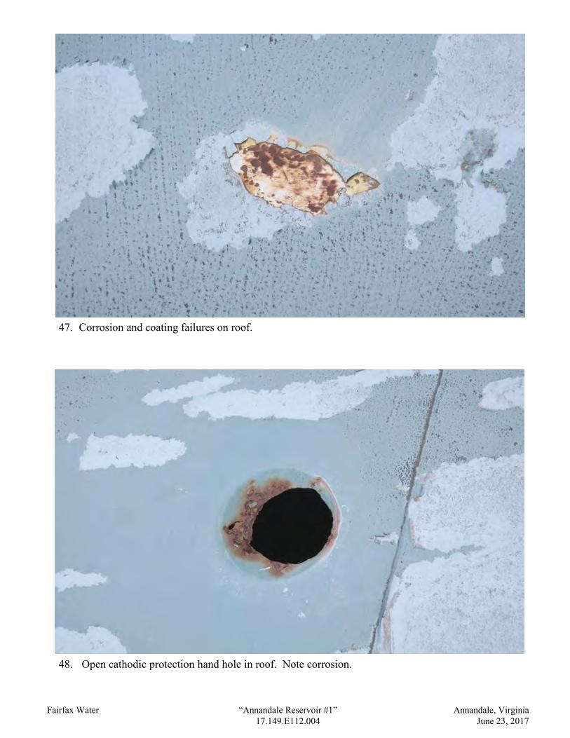
Fairfax Water “Annandale Reservoir #1” Annandale, Virginia 17.149.E112.004 June 23, 2017
47. Corrosion and coating failures on roof.
48. Open cathodic protection hand hole in roof. Note corrosion.

Fairfax Water “Annandale Reservoir #1” Annandale, Virginia 17.149.E112.004 June 23, 2017
49. Cathodic protection hand hole cover in roof.
50. Roof vent.

Fairfax Water “Annandale Reservoir #1” Annandale, Virginia 17.149.E112.004 June 23, 2017
51. Roof vent screening.
52. Roof vent.

Fairfax Water “Annandale Reservoir #1” Annandale, Virginia 17.149.E112.004 June 23, 2017
53. Roof vent screening.
54. Clog-resistant roof vent.

Fairfax Water “Annandale Reservoir #1” Annandale, Virginia 17.149.E112.004 June 23, 2017
55. Roof vent pallet.
56. Roof interior and support structure.
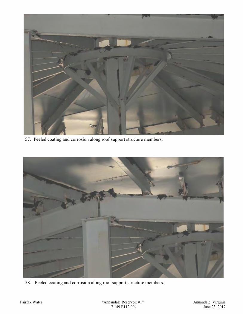
Fairfax Water “Annandale Reservoir #1” Annandale, Virginia 17.149.E112.004 June 23, 2017
57. Peeled coating and corrosion along roof support structure members.
58. Peeled coating and corrosion along roof support structure members.

Fairfax Water “Annandale Reservoir #1” Annandale, Virginia 17.149.E112.004 June 23, 2017
59. Peeled coating and corrosion along roof support structure members.
60. Peeled coating and corrosion along roof seams and rafter.

Fairfax Water “Annandale Reservoir #1” Annandale, Virginia 17.149.E112.004 June 23, 2017
61. Peeled coating and corrosion along roof seams and rafter.
62. Peeled coating and corrosion along roof seams and rafters. Note daylight at misaligned and
uncovered hand holes.

Fairfax Water “Annandale Reservoir #1” Annandale, Virginia 17.149.E112.004 June 23, 2017
63. Peeled coating and corrosion along rafter edge and roof-to-shell connection.
64. Peeled coating and corrosion along roof-to-shell connection.

Fairfax Water “Annandale Reservoir #1” Annandale, Virginia 17.149.E112.004 June 23, 2017
65. Overflow inlet weir box.
66. Columns and shell.

Fairfax Water “Annandale Reservoir #1” Annandale, Virginia 17.149.E112.004 June 23, 2017
67. Shell interior. Note daylight at uncovered hand holes.
68. Shell interior.

Fairfax Water “Annandale Reservoir #1” Annandale, Virginia 17.149.E112.004 June 23, 2017
69. Interior ladder, safe-climbing device, and cathodic protection reference electrode.
70. Deposits on interior ladder safe-climbing device.

Fairfax Water “Annandale Reservoir #1” Annandale, Virginia 17.149.E112.004 June 23, 2017
71. Silt on floor, base of interior ladder, and cathodic protection reference electrode.
72. Cathodic protection equipment on shell.
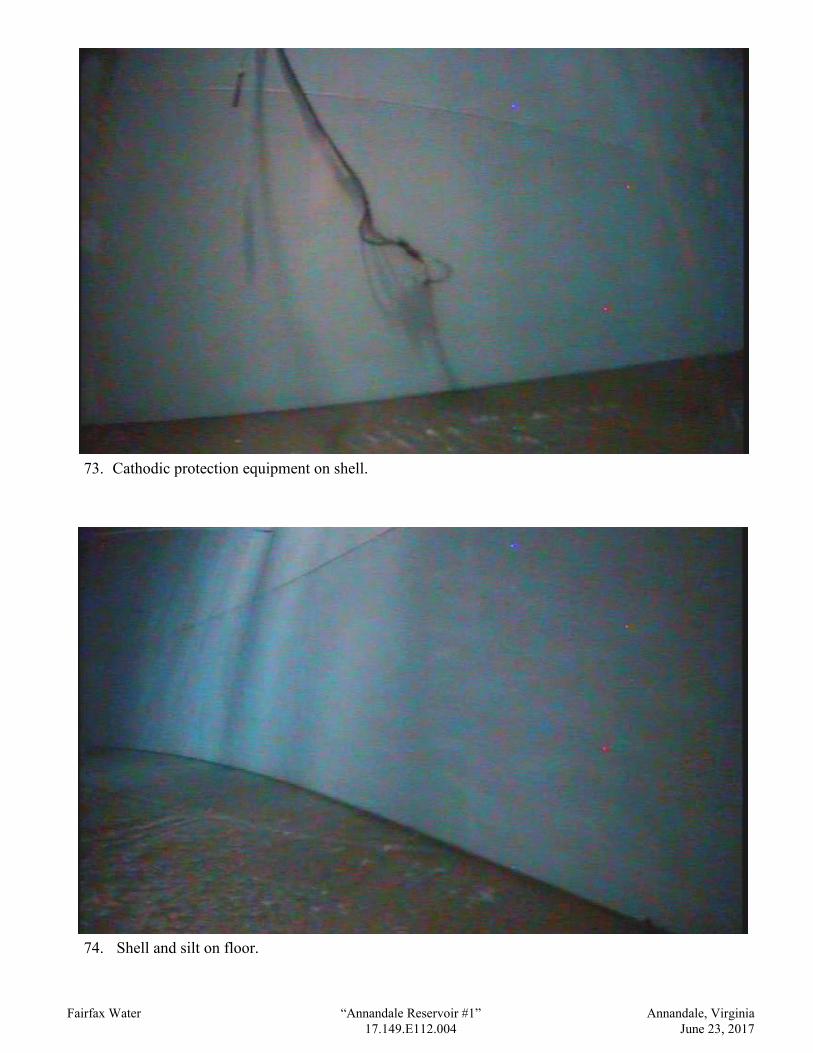
Fairfax Water “Annandale Reservoir #1” Annandale, Virginia 17.149.E112.004 June 23, 2017
73. Cathodic protection equipment on shell.
74. Shell and silt on floor.

Fairfax Water “Annandale Reservoir #1” Annandale, Virginia 17.149.E112.004 June 23, 2017
75. Shell and silt on floor.
76. Silt on floor.

Fairfax Water “Annandale Reservoir #1” Annandale, Virginia 17.149.E112.004 June 23, 2017
77. Silt on floor and column bases.
78. Column base.

Fairfax Water “Annandale Reservoir #1” Annandale, Virginia 17.149.E112.004 June 23, 2017
79. Interior piping.
80. Interior piping.

Fairfax Water “Annandale Reservoir #1” Annandale, Virginia 17.149.E112.004 October 31, 2017
81. Coating failures and corrosion on roof exterior.
82. Hole in roof.

Fairfax Water “Annandale Reservoir #1” Annandale, Virginia 17.149.E112.004 October 31, 2017
83. Roof interior, rafters, center hub, and column. Note peeled coating and rust.
84. Peeled coating and rust on roof rafters, center hub, and column.

Fairfax Water “Annandale Reservoir #1” Annandale, Virginia 17.149.E112.004 October 31, 2017
85. Peeled coating and rust on center column.
86. Roof interior, rafters, girders, and columns. Note peeled coating and rust.

Fairfax Water “Annandale Reservoir #1” Annandale, Virginia 17.149.E112.004 October 31, 2017
87. Roof interior, rafters, girders, and columns. Note peeled coating and rust.
88. Roof interior, rafters, girders, and columns. Note peeled coating and rust.
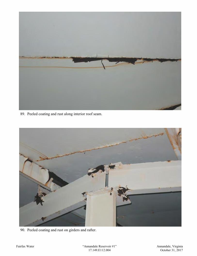
Fairfax Water “Annandale Reservoir #1” Annandale, Virginia 17.149.E112.004 October 31, 2017
89. Peeled coating and rust along interior roof seam.
90. Peeled coating and rust on girders and rafter.

Fairfax Water “Annandale Reservoir #1” Annandale, Virginia 17.149.E112.004 October 31, 2017
91. Peeled coating and corrosion on roof rafters near girder.
92. Peeled coating and corrosion on roof rafters near girder.

Fairfax Water “Annandale Reservoir #1” Annandale, Virginia 17.149.E112.004 October 31, 2017
93. Peeled coating, corrosion, and metal loss on roof rafters near girder.
94. Peeled coating and corrosion on roof rafter near girder.

Fairfax Water “Annandale Reservoir #1” Annandale, Virginia 17.149.E112.004 October 31, 2017
95. Peeled coating and corrosion on roof rafter near girder.
96. Hole in roof.

Fairfax Water “Annandale Reservoir #1” Annandale, Virginia 17.149.E112.004 October 31, 2017
97. Peeled coating and corrosion on roof rafters near shell.
98. Peeled coating and corrosion on roof rafters near shell. Note daylight at holes in roof.

Fairfax Water “Annandale Reservoir #1” Annandale, Virginia 17.149.E112.004 October 31, 2017
99. Peeled coating and corrosion on roof rafter bracket on shell.
100. Peeled coating and corrosion on roof rafter bracket on shell.

Fairfax Water “Annandale Reservoir #1” Annandale, Virginia 17.149.E112.004 October 31, 2017
101. Corrosion along top shell angle.
102. Overflow weir box.

Photographs from Annandale Reservoir #2 Evaluation Report October 31, 2017 and May 22, 2018
(These photos are provided for information only and do not modify the project plans or specifications. Conditions are not intended as representations or warranties of accuracy
of all existing conditions. The Owner and Engineer will not be responsible for interpretations or conclusions drawn from this information by the Contractor.)

Fairfax Water “Annandale Reservoir #2” Annandale, Virginia 17.071.E112.005
1. Tank.
2. Tank and site.

Fairfax Water “Annandale Reservoir #2” Annandale, Virginia 17.071.E112.005
3. Surrounding area.
4. Adjacent ground storage tank.

Fairfax Water “Annandale Reservoir #2” Annandale, Virginia 17.071.E112.005
5. Adjacent antenna tower and ground storage tank.
6. Access to site.
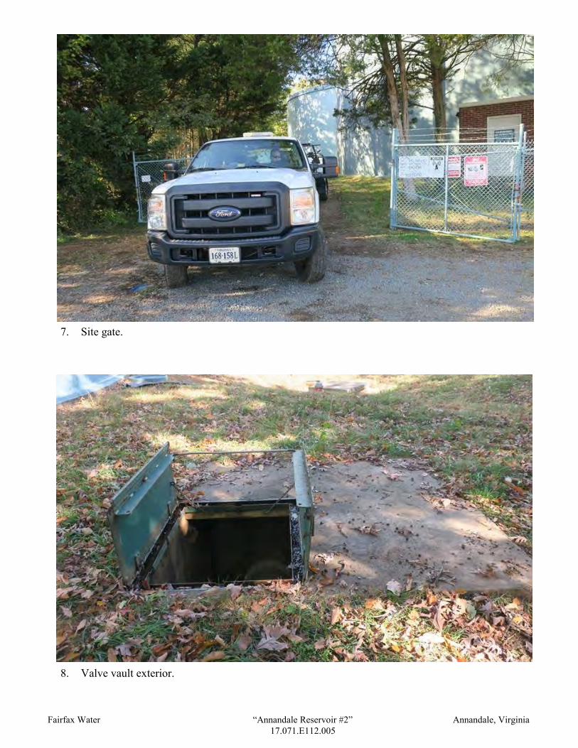
Fairfax Water “Annandale Reservoir #2” Annandale, Virginia 17.071.E112.005
7. Site gate.
8. Valve vault exterior.
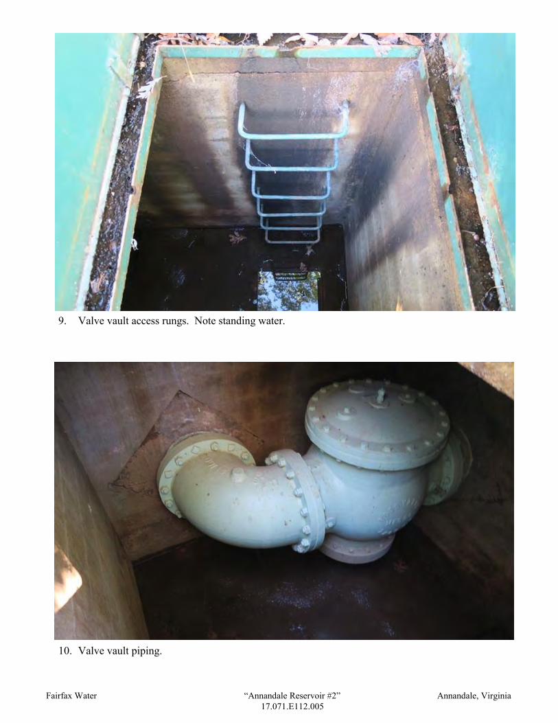
Fairfax Water “Annandale Reservoir #2” Annandale, Virginia 17.071.E112.005
9. Valve vault access rungs. Note standing water.
10. Valve vault piping.

Fairfax Water “Annandale Reservoir #2” Annandale, Virginia 17.071.E112.005
11. Electrical cabinet adjacent to tank.
12. Tank foundation.

Fairfax Water “Annandale Reservoir #2” Annandale, Virginia 17.071.E112.005
13. Debris, spalling, and peeled coating on foundation, and vegetation growing at grout.
14. Cracked repairs in foundation.

Fairfax Water “Annandale Reservoir #2” Annandale, Virginia 17.071.E112.005
15. Spalling in foundation.
16. Mildew at grout.

Fairfax Water “Annandale Reservoir #2” Annandale, Virginia 17.071.E112.005
17. Peeled sealant material and minor corrosion on bottom plate projection.
18. Shell manhole.

Fairfax Water “Annandale Reservoir #2” Annandale, Virginia 17.071.E112.005
19. Shell manhole, unused tank nameplate bracket, and touched-up shell coating.
20. Cathodic protection cabinet.

Fairfax Water “Annandale Reservoir #2” Annandale, Virginia 17.071.E112.005
21. Cathodic protection equipment penetrating shell.
22. Shell exterior.

Fairfax Water “Annandale Reservoir #2” Annandale, Virginia 17.071.E112.005
23. Overflow pipe discharge above grate-covered drain basin.
24. Overflow pipe along shell.

Fairfax Water “Annandale Reservoir #2” Annandale, Virginia 17.071.E112.005
25. Exterior ladder, vandal deterrent, safe-climbing device, and conduit.
26. Shell exterior.

Fairfax Water “Annandale Reservoir #2” Annandale, Virginia 17.071.E112.005
27. Exterior shell rail.
28. Debris along top of exterior shell rail.

Fairfax Water “Annandale Reservoir #2” Annandale, Virginia 17.071.E112.005
29. Overflow pipe and exterior shell rail. Note peeled overflow pipe coating.
30. Roof access, roof safety railing, and roof manhole.

Fairfax Water “Annandale Reservoir #2” Annandale, Virginia 17.071.E112.005
31. Closure chains at roof access.
32. Roof manhole. Note debris.

Fairfax Water “Annandale Reservoir #2” Annandale, Virginia 17.071.E112.005
33. Hole in roof manhole neck.
34. Antenna guyed wires and welded reinforcing plate.

Fairfax Water “Annandale Reservoir #2” Annandale, Virginia 17.071.E112.005
35. Peeled coating and corrosion on roof.
36. Peeled coating on roof.

Fairfax Water “Annandale Reservoir #2” Annandale, Virginia 17.071.E112.005
37. Peeled coating on roof.
38. Roof safety railing and roof manhole.
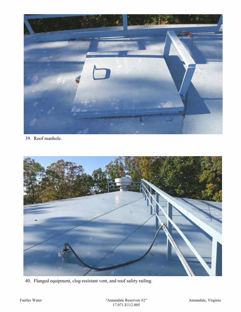
Fairfax Water “Annandale Reservoir #2” Annandale, Virginia 17.071.E112.005
39. Roof manhole.
40. Flanged equipment, clog-resistant vent, and roof safety railing.

Fairfax Water “Annandale Reservoir #2” Annandale, Virginia 17.071.E112.005
41. Flanged roof equipment.
42. Welded steel circular patch plates.

Fairfax Water “Annandale Reservoir #2” Annandale, Virginia 17.071.E112.005
43. Corrosion at threaded and plugged roof coupling.
44. Corrosion on outer roof vent cover.

Fairfax Water “Annandale Reservoir #2” Annandale, Virginia 17.071.E112.005
45. Corrosion on roof vent. Note loose bracket.
46. Corrosion on outer roof vent cover.

Fairfax Water “Annandale Reservoir #2” Annandale, Virginia 17.071.E112.005
47. Corrosion on roof vent.
48. Clog-resistant vent. Note corrosion at welded steel patch plates in roof.

Fairfax Water “Annandale Reservoir #2” Annandale, Virginia 17.071.E112.005
49. Clog-resistant vent.
50. Roof interior and support structure.
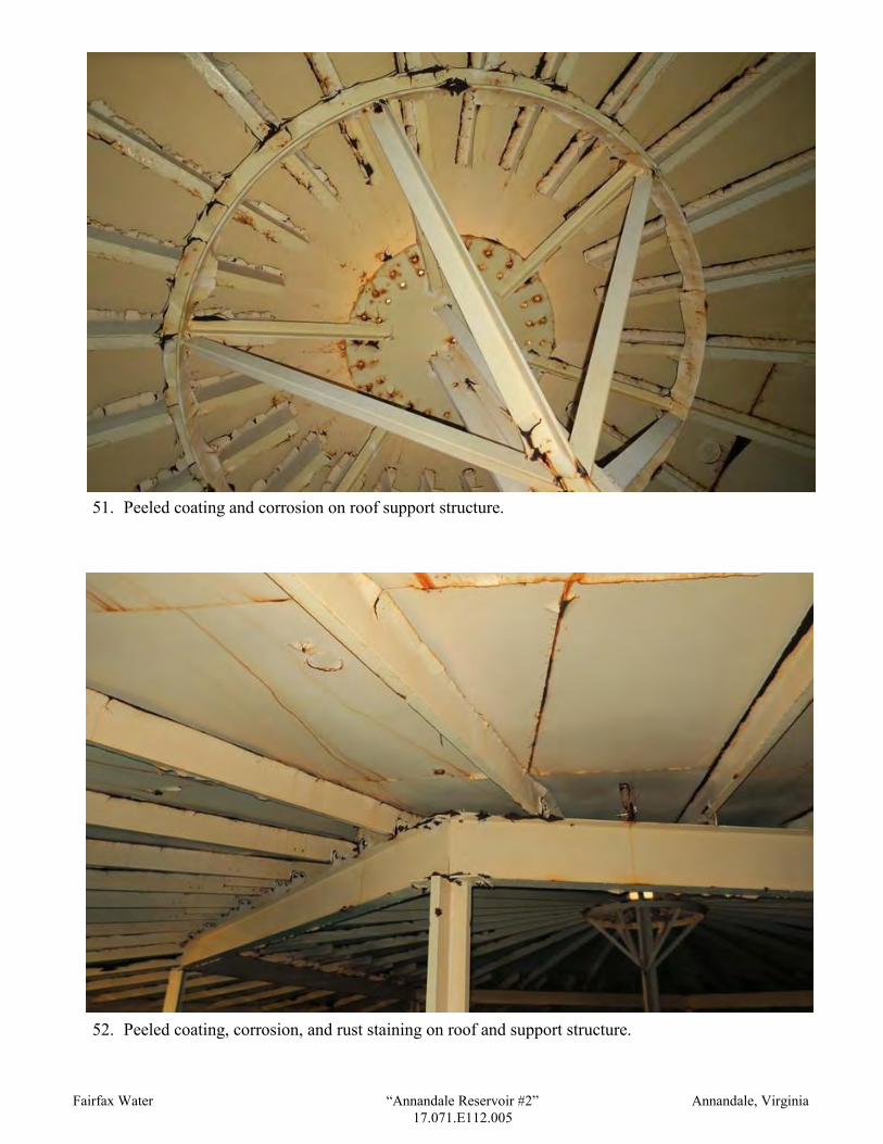
Fairfax Water “Annandale Reservoir #2” Annandale, Virginia 17.071.E112.005
51. Peeled coating and corrosion on roof support structure.
52. Peeled coating, corrosion, and rust staining on roof and support structure.

Fairfax Water “Annandale Reservoir #2” Annandale, Virginia 17.071.E112.005
53. Peeled coating, corrosion, and rust staining on roof and support structure.
54. Corrosion and metal loss along rafter flanges and on roof surfaces opposite rafter.

Fairfax Water “Annandale Reservoir #2” Annandale, Virginia 17.071.E112.005
55. Peeled coating, corrosion, rust staining, and metal loss on roof and support structure.
56. Peeled coating, corrosion, and rust staining on roof and support structure.

Fairfax Water “Annandale Reservoir #2” Annandale, Virginia 17.071.E112.005
57. Peeled coating, corrosion, and rust staining on roof and support structure.
58. Peeled coating, corrosion, and metal loss along roof seam.

Fairfax Water “Annandale Reservoir #2” Annandale, Virginia 17.071.E112.005
59. Peeled coating, corrosion, and metal loss along roof seam and rafter flanges.
60. Peeled coating, corrosion, and metal loss along rafter and interface with roof.

Fairfax Water “Annandale Reservoir #2” Annandale, Virginia 17.071.E112.005
61. Peeled coating along rafter and interface with roof.
62. Peeled coating along rafter.

Fairfax Water “Annandale Reservoir #2” Annandale, Virginia 17.071.E112.005
63. Corrosion and rust staining along rafter and peeled coating and corrosion along roof-to-shell
connection.
64. Peeled coating, corrosion, and metal loss at rafter attachment clip to shell and along roof-to-shell
connection.

Fairfax Water “Annandale Reservoir #2” Annandale, Virginia 17.071.E112.005
65. Peeled coating, corrosion, and metal loss at rafter attachment clip to shell and along roof-to-shell
connection.
66. Peeled coating, corrosion, and metal loss along roof-to-shell connection.

Fairfax Water “Annandale Reservoir #2” Annandale, Virginia 17.071.E112.005
67. Peeled coating, corrosion, and metal loss along roof-to-shell connection.
68. Overflow inlet.

Fairfax Water “Annandale Reservoir #2” Annandale, Virginia 17.071.E112.005
69. Peeled coating, corrosion, and metal loss on column.
70. Interior ladder and safe-climbing device.

Fairfax Water “Annandale Reservoir #2” Annandale, Virginia 17.071.E112.005
71. Interior ladder and bracket.
72. Corrosion on bracket at base of interior ladder.

Fairfax Water “Annandale Reservoir #2” Annandale, Virginia 17.071.E112.005
73. Previous metal loss in shell.
74. Cathodic protection equipment on shell.

Fairfax Water “Annandale Reservoir #2” Annandale, Virginia 17.071.E112.005
75. Shell manhole interior.
76. Shell manhole interior.

Fairfax Water “Annandale Reservoir #2” Annandale, Virginia 17.071.E112.005
77. Shell manhole interior.
78. Cathodic protection equipment.

Fairfax Water “Annandale Reservoir #2” Annandale, Virginia 17.071.E112.005
79. Cathodic protection reference electrode.
80. Floor.

Fairfax Water “Annandale Reservoir #2” Annandale, Virginia 17.071.E112.005
81. Silt on floor.
82. Silt on floor.

Fairfax Water “Annandale Reservoir #2” Annandale, Virginia 17.071.E112.005
83. Mud guard not attached on inlet/outlet pipe.
84. Column base.

Fairfax Water “Annandale Reservoir #2” Annandale, Virginia 17.071.E112.005
85. Silt on floor and column base.


