GATE Electronics and Communication Topicwise Solved Paper by RK Kanodia & Ashish Murolia Page 156 GATE Electronics & Communication by RK Kanodia Now in 3 Volume Purchase Online at maximum discount from online store and get POSTAL and Online Test Series Free visit www.nodia.co.in For more GATE Resources, Mock Test and Study material join the community http://www.facebook.com/gateec2014 UNIT 7 CONTROL SYSTEMS 2013 ONE MARK 7.1 The Bode plot of a transfer function Gs ^h is shown in the figure below. The gain log Gs 20 ^ _ h i is 32 dB and 8 dB at 1 / rad s and 10 / rad s respectively. The phase is negative for all . Then Gs ^h is (A) . s 39 8 (B) . s 39 8 2 (C) s 32 (D) s 32 2 2013 TWO MARKS 7.2 The open-loop transfer function of a dc motor is given as V s s s 1 10 10 a ^ ^ h h . When connected in feedback as shown below, the approximate value of K a that will reduce the time constant of the closed loop system by one hundred times as compared to that of the open-loop system is (A) 1 (B) 5 (C) 10 (D) 100 7.3 The signal flow graph for a system is given below. The transfer function Us Ys ^ ^ h h for this system is (A) s s s 5 6 2 1 2 (B) s s s 6 2 1 2 (C) s s s 4 2 1 2 (D) s s 5 6 2 1 2 Statement for Linked Answer Questions 4 and 5: The state diagram of a system is shown below. A system is described by the state-variable equations u X AX B o ; y u CX D 7.4 The state-variable equations of the system shown in the figure above are (A) u y u X X X 1 1 0 1 1 1 1 1 o > > 6 H H @ (B) u y u X X X 1 1 0 1 1 1 1 1 o > > 6 H H @ (C) u y u X X X 1 1 0 1 1 1 1 1 o > > 6 H H @ (D) u y u X X X 1 0 1 1 1 1 1 1 o > > 6 H H @ 7.5 The state transition matrix e At of the system shown in the figure above is (A) e te e 0 t t t > H (B) e te e 0 t t t > H (C) e e e 0 t t t > H (D) e te e 0 t t t > H 2012 ONE MARK 7.6 A system with transfer function () ( )( )( ) ( )( ) Gs s s s s s 1 3 4 9 2 2 is excited by ( ) sin t . The steady-state output of the system is zero at
Transcript
GATE Electronics and Communication Topicwise Solved Paper by RK Kanodia & Ashish Murolia Page 156
GATE Electronics & Communication
by RK Kanodia
Now in 3 Volume
Purchase Online at maximum discount from online storeand get POSTAL and Online Test Series Free
visit www.nodia.co.in
For more GATE Resources, Mock Test and
Study material join the community
http://www.facebook.com/gateec2014
UNIT 7CONTROL SYSTEMS
2013 ONE MARK
7.1 The Bode plot of a transfer function G s^ h is shown in the figure below.
The gain log G s20 ^_ h i is 32 dB and 8 dB at 1 /rad s and
10 /rad s respectively. The phase is negative for all . Then G s^ h is(A) .
s39 8 (B) .
s39 8
2
(C) s32 (D)
s32
2
2013 TWO MARKS
7.2 The open-loop transfer function of a dc motor is given as
V s
s
s1 1010
a ^^hh
. When connected in feedback as shown below, the
approximate value of Ka that will reduce the time constant of the closed loop system by one hundred times as compared to that of the open-loop system is
(A) 1 (B) 5
(C) 10 (D) 100
7.3 The signal flow graph for a system is given below. The transfer
function U s
Y s
^^hh for this system is
(A) s ss
5 6 21
2 (B) s ss
6 21
2
(C) s ss
4 21
2 (D) s s5 6 2
12
Statement for Linked Answer Questions 4 and 5:
The state diagram of a system is shown below. A system is
described by the state-variable equations uX AX Bo ;
y uCX D
7.4 The state-variable equations of the system shown in the figure above are
(A) u
y u
X X
X
1
1
0
1
1
1
1 1
o > >6
H H@
(B) u
y u
X X
X
1
1
0
1
1
1
1 1
o > >6
H H@
(C) u
y u
X X
X
1
1
0
1
1
1
1 1
o > >6
H H@
(D) u
y u
X X
X
1
0
1
1
1
1
1 1
o > >6
H H@
7.5 The state transition matrix eAt of the system shown in the figure
above is
(A) e
te e
0t
t t> H (B) e
te e
0t
t t> H(C)
e
e e
0t
t t> H (D) e te
e0
t t
t> H2012 ONE MARK
7.6 A system with transfer function ( )( )( )( )
( )( )G s
s s s
s s
1 3 49 22
is excited by ( )sin t . The steady-state output of the system is zero at
GATE Electronics and Communication Topicwise Solved Paper by RK Kanodia & Ashish Murolia Page 157
SPECIAL EDITION ( STUDY MATERIAL FORM )
At market Book is available in 3 volume i.e. in 3 book binding form. But at NODIA Online Store book is available in 10 book
binding form. Each unit of Book is in separate binding.Available Only at NODIA Online Store
Click to Buywww.nodia.co.in
(A) 1 /rad s (B) /rad s2
(C) /rad s3 (D) /rad s4
2012 TWO MARKS
7.7 The feedback system shown below oscillates at 2 /rad s when
(A) 2 0.75andK a (B) 3 0.75andK a
(C) 4 0.5andK a (D) 2 0.5andK a
7.8 The state variable description of an LTI system is given by
x
x
x
1
2
3
o
o
o
J
L
KKK
N
P
OOO
0
a
a
a
x
x
x
u
0
0 0
0 0
0
0
13
1
2
1
2
3
J
L
KKK
J
L
KKK
J
L
KKK
N
P
OOO
N
P
OOO
N
P
OOO
y
x
x
x
1 0 01
2
3
J
L
KKK
_N
P
OOO
iwhere y is the output and u is the input. The system is control-lable for(A) 0, 0, 0a a a1 2 3! ! (B) 0, 0, 0a a a1 2 3! !
(C) 0, 0, 0a a a1 3 3! (D) 0, 0, 0a a a1 2 3! !
2011 ONE MARK
7.9 The root locus plot for a system is given below. The open loop transfer function corresponding to this plot is given by
(A) ( )( )
( )G s H s k
s s
s s
2 31^ ^h h
(B) ( )( )
( )G s H s k
s s s
s
2 3
12^ ^h h
(C) ( )( )( )
G s H s ks s s s1 2 3
1^ ^h h(D)
( )( )( )
G s H s ks s s
s
2 31^ ^h h
7.10 For the transfer function ( )G j j5 , the corresponding Nyquist plot for positive frequency has the form
2011 TWO MARKS
7.11 The block diagram of a system with one input u and two outputs y1 and y2 is given below.
A state space model of the above system in terms of the state vec-tor x and the output vector [ ]y y y T
1 2 is(A) [2] [1] ; [ ]x x u y x1 2o
(B) [ ] [ ] ;x x u y x2 11
2o > H
(C) ;x x u y x2
0
0
2
1
11 2o > > 8H H B
(D) ;x x u y x2
0
0
2
1
1
1
2o > > >H H H
Common Data For Q. 7.4 & 7.5
The input-output transfer function of a plant ( )( )
H ss s 10
1002 .
The plant is placed in a unity negative feedback configuration as shown in the figure below.
GATE Electronics and Communication Topicwise Solved Paper by RK Kanodia & Ashish Murolia Page 158
GATE Electronics & Communication
by RK Kanodia
Now in 3 Volume
Purchase Online at maximum discount from online storeand get POSTAL and Online Test Series Free
visit www.nodia.co.in
For more GATE Resources, Mock Test and
Study material join the community
http://www.facebook.com/gateec2014
7.12 The gain margin of the system under closed loop unity negative feedback is(A) 0 dB (B) 20 dB
(C) 26 dB (D) 46 dB
7.13 The signal flow graph that DOES NOT model the plant transfer function ( )H s is
2010 ONE MARK
7.14 The transfer function ( )/ ( )Y s R s of the system shown is
(A) 0 (B) s 1
1
(C) s 1
2 (D) s 3
2
7.15 A system with transfer function ( )( )X s
Y ss ps has an output
( ) cosy t t23a k
for the input signal ( ) cosx t p t22a k. Then, the system param-
eter p is
(A) 3 (B) 2/ 3
(C) 1 (D) /3 2
7.16 For the asymptotic Bode magnitude plot shown below, the system transfer function can be
(A) . ss
0 1 110 1 (B)
. ss
0 1 1100 1
(C) ss
10 1100 (D) .
ss
10 10 1 1
2010 TWO MARKS
7.17 A unity negative feedback closed loop system has a plant with the
transfer function ( )G ss s2 2
12 and a controller ( )G sc in the
feed forward path. For a unit set input, the transfer function of the controller that gives minimum steady state error is
(A) ( )G sss
21
c (B) ( )G sss
12
c
(C) ( )( )( )( )( )
G ss s
s s
2 31 4
c (D) ( )G ss
s1 2 3c
Common Data For Q. 7.10 & 7.11 :
The signal flow graph of a system is shown below:
7.18 The state variable representation of the system can be
(A)
[ . ]
x x u
y x
1
1
1
0
0
2
0 0 5
o
o
> >H H (B)
.
x x u
y x
1
1
1
0
0
2
0 0 5
o
o
> >8
H HB
(C)
. .
x x u
y x
1
1
1
0
0
2
0 5 0 5
o
o
> >8
H HB
(D)
. .
x x u
y x
1
1
1
0
0
2
0 5 0 5
o
o
> >8
H HB
7.19 The transfer function of the system is
(A) ss
11
2 (B) ss
11
2
(C) s ss
11
2 (D) s ss
11
2
2009 ONE MARK
7.20 The magnitude plot of a rational transfer function ( )G s with real coefficients is shown below. Which of the following compensators has such a magnitude plot ?
(A) Lead compensator (B) Lag compensator
GATE Electronics and Communication Topicwise Solved Paper by RK Kanodia & Ashish Murolia Page 159
SPECIAL EDITION ( STUDY MATERIAL FORM )
At market Book is available in 3 volume i.e. in 3 book binding form. But at NODIA Online Store book is available in 10 book
binding form. Each unit of Book is in separate binding.Available Only at NODIA Online Store
Click to Buywww.nodia.co.in
(C) PID compensator (D) Lead-lag compensator
7.21 Consider the system
dtdx Ax Bu with A
1
0
0
1= G and Bp
q= G
where p and q are arbitrary real numbers. Which of the following
statements about the controllability of the system is true ?(A) The system is completely state controllable for any nonzero
values of p and q
(B) Only p 0 and q 0 result in controllability
(C) The system is uncontrollable for all values of p and q
(D) We cannot conclude about controllability from the given data
2009 TWO MARKS
7.22 The feedback configuration and the pole-zero locations of
( )G s s s
s s
2 22 2
2
2
are shown below. The root locus for negative values of k , i.e. for
k 03 , has breakaway/break-in points and angle of depar-ture at pole P (with respect to the positive real axis) equal to
(A) 2! and 0c (B) 2! and 45c
(C) 3! and 0c (D) 3! and 45c
7.23 The unit step response of an under-damped second order system has steady state value of -2. Which one of the following transfer functions has theses properties ?
(A) . .
.s s2 59 1 12
2 242
(B) . .
.s s1 91 1 91
3 822
(C) . .
.s s2 59 1 12
2 242
(D) . .s s1 91 1 91
3822
Common Data For Q. 7.16 and 7.17 :
The Nyquist plot of a stable transfer function ( )G s is shown in the figure are interested in the stability of the closed loop system in the feedback configuration shown.
7.24 Which of the following statements is true ?(A) ( )G s is an all-pass filter
(B) ( )G s has a zero in the right-half plane
(C) ( )G s is the impedance of a passive network
(D) ( )G s is marginally stable
7.25 The gain and phase margins of ( )G s for closed loop stability are(A) 6 dB and 180c
(B) 3 dB and 180c
(C) 6 dB and 90c
(D) 3 dB and 90c
2008 ONE MARKS
7.26 Step responses of a set of three second-order underdamped systems all have the same percentage overshoot. Which of the following diagrams represents the poles of the three systems ?
7.27 The pole-zero given below correspond to a
(A) Law pass filter (B) High pass filter
(C) Band filter (D) Notch filter
GATE Electronics and Communication Topicwise Solved Paper by RK Kanodia & Ashish Murolia Page 160
GATE Electronics & Communication
by RK Kanodia
Now in 3 Volume
Purchase Online at maximum discount from online storeand get POSTAL and Online Test Series Free
visit www.nodia.co.in
For more GATE Resources, Mock Test and
Study material join the community
http://www.facebook.com/gateec2014
2008 TWO MARKS
7.28 Group I lists a set of four transfer functions. Group II gives a list of possible step response ( )y t . Match the step responses with the corresponding transfer functions.
(A) , , ,P Q R S3 1 4 2 (B) , , ,P Q R S3 2 4 1
(C) , , ,P Q R S2 1 4 2 (D) , , ,P Q R S3 4 1 2
7.29 A signal flow graph of a system is given below
The set of equalities that corresponds to this signal flow graph is
(A) dtdx
x
x
x
x
x
u
u
0
0
0
0
0
1
0
1
0
1
2
3
1
2
3
1
2
����� ����� e�� ��� �� ��� o
������ ������ ���� ����(B) dtdx
x
x
x
x
x
u
u
0
0
0
1
0
0
0
1
0
1
2
3
1
2
3
1
2
����� ����� e�� ��� �� ��� o
������ ������ ���� ����(C) dtdx
x
x
x
x
x
u
u
0
0
0
1
0
0
0
1
0
1
2
3
1
2
3
1
2
����� ����� e�� ��� �� ��� o
������ ������ ���� ����(D) dtdx
x
x
x
x
x
u
u
0
0
0
1
0
0
0
1
0
1
2
3
1
2
3
1
2
����� ����� e�� ��� �� ��� o
������ ������ ���� ����7.30 A certain system has transfer function
( )G s s s
s
48
2
where is a parameter. Consider the standard negative unity feedback configuration as shown below
Which of the following statements is true?(A) The closed loop systems is never stable for any value of
(B) For some positive value of , the closed loop system is stable,
GATE Electronics and Communication Topicwise Solved Paper by RK Kanodia & Ashish Murolia Page 161
SPECIAL EDITION ( STUDY MATERIAL FORM )
At market Book is available in 3 volume i.e. in 3 book binding form. But at NODIA Online Store book is available in 10 book
binding form. Each unit of Book is in separate binding.Available Only at NODIA Online Store
Click to Buywww.nodia.co.in
but not for all positive values.
(C) For all positive values of , the closed loop system is stable.
(D) The closed loop system stable for all values of , both positive and negative.
7.31 The number of open right half plane of
( )G s s s s s s2 3 6 5 3
105 4 3 2
is
(A) 0 (B) 1
(C) 2 (D) 3
7.32 The magnitude of frequency responses of an underdamped second
order system is 5 at 0 rad/sec and peaks to 3
10 at 5 2 rad/sec. The transfer function of the system is
(A) s s10 100
5002
(B) s s5 75
3752
(C) s s12 144
7202
(D) s s25 225
11252
7.33 Group I gives two possible choices for the impedance Z in the diagram. The circuit elements in Z satisfy the conditions R C R C2 2 1 1. The
transfer functions VV
i
0 represents a kind of controller.
Match the impedances in Group I with the type of controllers in Group II
(A) ,Q R1 2 (B) ,Q R1 3
(C) ,Q R2 3 (D) ,Q R3 2
2007 ONE MARK
7.34 If the closed-loop transfer function of a control system is given as
( )( )( )
T ss ss2 3
5 , then It is
(A) an unstable system (B) an uncontrollable system
(C) a minimum phase system (D) a non-minimum phase sys-tem
2007 TWO MARKS
7.35 A control system with PD controller is shown in the figure. If the velocity error constant K 1000V and the damping ratio .0 5, then the value of KP and KD are
(A) 100, 0.09K KP D (B) 100, 0.9K KP D
(C) 10, 0.09K KP D (D) 10, 0.9K KP D
7.36 The transfer function of a plant is
( )T s ( )( )s s s5 1
52
The second-order approximation of ( )T s using dominant pole con-cept is
(A) ( )( )s s5 1
1 (B) ( )( )s s5 1
5
(C) s s 1
52
(D) s s 1
12
7.37 The open-loop transfer function of a plant is given as ( )G s1s
12 -
. If the plant is operated in a unity feedback configuration, then the lead compensator that an stabilize this control system is
(A) ( )s
s
210 1
(B) ( )s
s
210 4
(C) ( )s
s
1010 2
(D) ( )s
s
102 2
7.38 A unity feedback control system has an open-loop transfer function
( )( )
G ss s s
K
7 122
The gain K for which s j1 1 will lie on the root locus of this
system is(A) 4 (B) 5.5
(C) 6.5 (D) 10
7.39 The asymptotic Bode plot of a transfer function is as shown in the figure. The transfer function ( )G s corresponding to this Bode plot is
(A) ( )( )s s1 20
1 (B) ( )( )s s s1 20
1
(C) ( )( )s s s1 20
100 (D) ( )( . )s s s1 1 0 05
100
7.40 The state space representation of a separately excited DC servo motor dynamics is given as
dtd
dtdio> H i
u1
1
1
10
0
10a= = =G G G
where is the speed of the motor, ia is the armature current and
u is the armature voltage. The transfer function ( )( )U s
s of the motor
is
(A) s s11 11
102
(B)s s11 11
12
(C) s s
s
11 1110 10
2 (D)
s s 111
2
Statement for linked Answer Question 8.33 & 8.34 :
GATE Electronics and Communication Topicwise Solved Paper by RK Kanodia & Ashish Murolia Page 162
GATE Electronics & Communication
by RK Kanodia
Now in 3 Volume
Purchase Online at maximum discount from online storeand get POSTAL and Online Test Series Free
visit www.nodia.co.in
For more GATE Resources, Mock Test and
Study material join the community
http://www.facebook.com/gateec2014
Consider a linear system whose state space representation is
( ) ( )x t Ax t . If the initial state vector of the system is ( )x 01
2= G, then the system response is ( )x t
e
e2
x
t
2
2> H. If the itial state vector
of the system changes to ( )x 01
2= G, then the system response
becomes ( )x te
e
t
t> H7.41 The eigenvalue and eigenvector pairs ( )vi i for the system are
(A) 11
1e o= G and 21
2e o= G (B) ,11
1e o= G and ,21
2e o= G(C) ,1
1
1e o= G and ,21
2e o= G (D) 21
1e o= G and ,11
2e o= G7.42 The system matrix A is
(A) 0
1
1
1= G (B) 1
1
1
2= G(C)
2
1
1
1= G (D) 0
2
1
3= G
2006 ONE MARK
7.43 The open-loop function of a unity-gain feedback control system is given by
( )G s ( )( )s s
K1 2
The gain margin of the system in dB is given by(A) 0 (B) 1
(C) 20 (D) 3
2006 TWO MARKS
7.44 Consider two transfer functions ( )G ss as b
11 2
and
( )G ss as b
s2 2
.
The 3-dB bandwidths of their frequency responses are, respectively
(A) ,a b a b4 42 2 (B) ,a b a b4 42 2
(C) ,a b a b4 42 2 (D) ,a b a b4 42 2
7.45 The Nyquist plot of ( ) ( )G j H j for a closed loop control system, passes through ( , )j1 0 point in the GH plane. The gain margin of the system in dB is equal to(A) infinite (B) greater than zero
(C) less than zero (D) zero
7.46 The positive values of K and a so that the system shown in the figures below oscillates at a frequency of 2 rad/sec respectively are
(A) 1, 0.75 (B) 2, 0.75
(C) 1, 1 (D) 2, 2
7.47 The transfer function of a phase lead compensator is given by
( )G sTsTs
11 3
c where T 0 The maximum phase shift provide by such a compensator is
(A) 2
(B) 3
(C) 4
(D) 6
7.48 A linear system is described by the following state equation
( )X to ( ) ( ),AX t BU t A0
1
1
0= GThe state transition matrix of the system is
(A) cos
sin
sin
cos
t
t
t
t= G (B)
cos
sin
sin
cos
t
t
t
t= G
(C) cos
sin
sin
cos
t
t
t
t= G (D)
cos
cos
sin
sin
t
t
t
t= G
Statement for Linked Answer Questions 7.41 & 7.42 :
Consider a unity - gain feedback control system whose open - loop
transfer function is : ( )G ss
as 12
7.49 The value of a so that the system has a phase - margin equal to 4
is approximately equal to(A) 2.40 (B) 1.40
(C) 0.84 (D) 0.74
7.50 With the value of a set for a phase - margin of 4
, the value of unit - impulse response of the open - loop system at t 1 second is equal to(A) 3.40 (B) 2.40
(C) 1.84 (D) 1.74
2005 ONE MARK
7.51 A linear system is equivalently represented by two sets of state equations :
Xo AX BU and W CW DUo
The eigenvalues of the representations are also computed as [ ]
and [ ]. Which one of the following statements is true ?(A) [ ] [ ] and X W (B) [ ] [ ] and X W!
(C) [ ] [ ]! and X W (D) [ ] [ ] and X W!
7.52 Which one of the following polar diagrams corresponds to a lag
network ?
GATE Electronics and Communication Topicwise Solved Paper by RK Kanodia & Ashish Murolia Page 163
SPECIAL EDITION ( STUDY MATERIAL FORM )
At market Book is available in 3 volume i.e. in 3 book binding form. But at NODIA Online Store book is available in 10 book
binding form. Each unit of Book is in separate binding.Available Only at NODIA Online Store
Click to Buywww.nodia.co.in
7.53 Despite the presence of negative feedback, control systems still have problems of instability because the(A) Components used have non- linearities(B) Dynamic equations of the subsystem are not known exactly.(C) Mathematical analysis involves approximations.(D) System has large negative phase angle at high frequencies.
2005 TWO MARKS
7.54 The polar diagram of a conditionally stable system for open loop gain K 1 is shown in the figure. The open loop transfer function of the system is known to be stable. The closed loop system is stable for
(A) K 5 and K21
81 (B) K
81 and K
21 5
(C) K81 and K5 (D) K
81 and K5
7.55 In the derivation of expression for peak percent overshoot
Mp %exp1
1002
#e oWhich one of the following conditions is NOT required ?(A) System is linear and time invariant
(B) The system transfer function has a pair of complex conjugate poles and no zeroes.
(C) There is no transportation delay in the system.
(D) The system has zero initial conditions.
7.56 A ramp input applied to an unity feedback system results in 5% steady state error. The type number and zero frequency gain of the system are respectively(A) 1 and 20 (B) 0 and 20
(C) 0 and 201 (D) 1 and
201
7.57 A double integrator plant ( ) / , ( )G s K s H s 12 is to be compensated to achieve the damping ratio .0 5 and an undamped natural frequency, 5n rad/sec which one of the following compensator
( )G se will be suitable ?
(A) ss
993 (B)
ss
399
(C) .s
s8 336 (D)
ss 6
7.58 An unity feedback system is given as ( )( )( )
G ss s
K s
31
.Indicate the correct root locus diagram.
Statement for Linked Answer Question 40 and 41 :
The open loop transfer function of a unity feedback system is given
by
( )G s ( )s se
23 s2
7.59 The gain and phase crossover frequencies in rad/sec are, respectively
(A) 0.632 and 1.26 (B) 0.632 and 0.485
(C) 0.485 and 0.632 (D) 1.26 and 0.632
7.60 Based on the above results, the gain and phase margins of the system will be(A) 7.09 dB and .87 5c (B) .7 09 dB and .87 5c
(C) .7 09 dB and .87 5c (D) .7 09 and .87 5c
2004 ONE MARK
7.61 The gain margin for the system with open-loop transfer function
( ) ( )G s H s ( )
s
s2 12
, is
(A) 3 (B) 0
(C) 1 (D) 3
7.62 Given ( ) ( )( )( )
G s H ss s s
K1 3
.The point of intersection of the asymptotes of the root loci with the real axis is(A) 4 (B) .1 33
(C) .1 33 (D) 4
2004 TWO MARKS
7.63 Consider the Bode magnitude plot shown in the fig. The transfer function ( )H s is
(A) ( )( )
( )s s
s
1 10010
(B) ( )( )
( )s s
s
10 10010 1
GATE Electronics and Communication Topicwise Solved Paper by RK Kanodia & Ashish Murolia Page 164
GATE Electronics & Communication
by RK Kanodia
Now in 3 Volume
Purchase Online at maximum discount from online storeand get POSTAL and Online Test Series Free
visit www.nodia.co.in
For more GATE Resources, Mock Test and
Study material join the community
http://www.facebook.com/gateec2014
(C) ( )( )
( )s s
s
10 10010 12
(D) ( )( )
( )s s
s
1 1010 1003
7.64 A causal system having the transfer function ( ) 1/( 2)H s s is excited with ( )u t10 . The time at which the output reaches 99% of its steady state value is(A) 2.7 sec (B) 2.5 sec
(C) 2.3 sec (D) 2.1 sec
7.65 A system has poles at 0.1 Hz, 1 Hz and 80 Hz; zeros at 5 Hz, 100 Hz and 200 Hz. The approximate phase of the system response at 20 Hz is(A) 90c (B) 0c
(C) 90c (D) 180c
7.66 Consider the signal flow graph shown in Fig. The gain xx
1
5 is
(A) ( )abcd
be cf dg1 (B)
( )be cf dg
bedg
1
(C) ( )be cf dg bedg
abcd1
(D) ( )
abcd
be cf dg bedg1
7.67 If A2
1
2
3= G, then sinAt is
(A) ( ) ( )
( ) ( )
( ) ( )
( ) ( )
sin sin
sin sin
sin sin
sin sin
t t
t t
t t
t t31 4 2
4
2 4 2
2 4= G(B)
( )
( )
( )
( )
sin
sin
sin
sin
t
t
t
t
2 2
3= G(C)
( ) ( )
( ) ( )
( ) ( )
( ) ( )
sin sin
sin sin
sin sin
sin sin
t t
t t
t t
t t31 4 2
4
2 4 2
2 4= G(D)
( ) ( )
( ) ( )
( ) ( )
( ) ( )
cos cos
cos cos
cos cos
cos cos
t t
t t
t t
t t31 2
4
2 4 2
2 4= G7.68 The open-loop transfer function of a unity feedback system is
( )G s ( )( )s s s s
K
2 32
The range of K for which the system is stable is
(A) K421 0 (B) K13 0
(C) K421
3 (D) K6 3
7.69 For the polynomial ( )P s s s s s s2 2 3 152 4 3 2 the number of roots which lie in the right half of the s plane is(A) 4 (B) 2
(C) 3 (D) 1
7.70 The state variable equations of a system are : ,x x x u x x3 21 1 2 2 1o o and y x u1 . The system is(A) controllable but not observable
(B) observable but not controllable
(C) neither controllable nor observable
(D) controllable and observable
7.71 Given A1
0
0
1= G, the state transition matrix eAt is given by
(A) e
e0
0t
t> H (B) e
e0
0t
t= G(C)
e
e0
0t
t> H (D) e
e0
0t
t= G2003 ONE MARK
7.72 Fig. shows the Nyquist plot of the open-loop transfer function
( ) ( )G s H s of a system. If ( ) ( )G s H s has one right-hand pole, the closed-loop system is
(A) always stable
(B) unstable with one closed-loop right hand pole
(C) unstable with two closed-loop right hand poles
(D) unstable with three closed-loop right hand poles
7.73 A PD controller is used to compensate a system. Compared to the uncompensated system, the compensated system has(A) a higher type number (B) reduced damping
7.74 The signal flow graph of a system is shown in Fig. below. The transfer function ( )/ ( )C s R s of the system is
(A) s s29 6
62
(B) s s
s
29 66
2
(C) ( )
s s
s s
29 6
22
(D) ( )
s s
s s
29 6
272
7.75 The root locus of system ( ) ( )G s H s ( )( )s s s
K2 3
has the break-
away point located at(A) ( . , )0 5 0 (B) ( . , )2 548 0
(C) ( , )4 0 (D) ( . , )0 784 0
7.76 The approximate Bode magnitude plot of a minimum phase system is shown in Fig. below. The transfer function of the system is
GATE Electronics and Communication Topicwise Solved Paper by RK Kanodia & Ashish Murolia Page 165
SPECIAL EDITION ( STUDY MATERIAL FORM )
At market Book is available in 3 volume i.e. in 3 book binding form. But at NODIA Online Store book is available in 10 book
binding form. Each unit of Book is in separate binding.Available Only at NODIA Online Store
Click to Buywww.nodia.co.in
(A) ( ) ( )
( . )
s s
s10
10 100
0 182
3
(B) ( )( )
( . )s s
s10
10 1000 17
3
(C) ( ) ( )
( . )
s s
s
10 100
0 12
2
(D) ( )( )
( . )
s s
s
10 100
0 12
3
7.77 A second-order system has the transfer function
( )( )R s
C s s s4 4
42
With ( )r t as the unit-step function, the response ( )c t of the system
is represented by
7.78 The gain margin and the phase margin of feedback system with
( ) ( )G s H s ( )s 100
83 are
(A) ,0dB c (B) ,3 3
(C) ,03 c (D) .88 5 dB, 3
7.79 The zero-input response of a system given by the state-space equationx
x
x
x
1
1
0
11
2
1
2
o
o= = =G G G and
( )
( )
x
x
0
0
1
01
2= =G G is
(A) te
t
t= G (B) e
t
t= G(C)
e
te
t
t= G (D) t
tet= G
2002 ONE MARK
7.80 Consider a system with transfer function ( )G sks s
s
66
2. Its
damping ratio will be 0.5 when the value of k is
(A) 62 (B) 3
(C) 61 (D) 6
7.81 Which of the following points is NOT on the root locus of a system
with the open-loop transfer function ( ) ( )G s H s ( )( )s s s
k1 3
(A) s j 3 (B) 1.5s
(C) s 3 (D) s 3
7.82 The phase margin of a system with the open - loop transfer function
( ) ( )G s H s ( )( )
( )s s
s
1 21
(A) 0c (B) .63 4c
(C) 90c (D) 3
7.83 The transfer function ( )/ ( )Y s U s of system described by the state equation ( ) ( ) ( )x t x t u t2 2o and ( ) . ( )y t x t0 5 is
(A) ( )
.s 20 5 (B)
( )s 21
(C) ( )
.s 20 5 (D)
( )s 21
2002 TWO MARKS
7.84 The system shown in the figure remains stable when(A) k 1 (B) k1 3
(C) k1 3 (D) k 3
7.85 The transfer function of a system is ( )( )( )
G ss s1 100
100 . For a
unit - step input to the system the approximate settling time for 2% criterion is
(A)100 sec (B) 4 sec
(C) 1 sec (D) 0.01 sec
7.86 The characteristic polynomial of a system is
( )q s s s s s s2 4 2 2 15 4 3 2
The system is(A) stable (B) marginally stable
(C) unstable (D) oscillatory
7.87 The system with the open loop transfer function
( ) ( )( )
G s H ss s s 1
12
has a gain margin of(A) 6 db (B) 0 db
(C) 35 db (D) 6 db
2001 ONE MARK
7.88 The Nyquist plot for the open-loop transfer function ( )G s of a unity negative feedback system is shown in the figure, if ( )G s has no pole in the right-half of s plane, the number of roots of the system characteristic equation in the right-half of s plane is(A) 0 (B) 1
(C) 2 (D) 3
7.89 The equivalent of the block diagram in the figure is given is
GATE Electronics and Communication Topicwise Solved Paper by RK Kanodia & Ashish Murolia Page 166
GATE Electronics & Communication
by RK Kanodia
Now in 3 Volume
Purchase Online at maximum discount from online storeand get POSTAL and Online Test Series Free
visit www.nodia.co.in
For more GATE Resources, Mock Test and
Study material join the community
http://www.facebook.com/gateec2014
7.90 If the characteristic equation of a closed - loop system is s s2 2 02
, then the system is(A) overdamped (B) critically damped
(C) underdamped (D) undamped
7.91 The root-locus diagram for a closed-loop feedback system is shown in the figure. The system is overdamped.
(A) only if k0 1# # (B) only if k1 5
(C) only if k 5 (D) if k0 1# or k 5
2001 TWO MARK
7.92 An electrical system and its signal-flow graph representations are shown the figure (A) and (B) respectively. The values of G2 and H, respectively are
(A) ( ) ( ) ( )
( ),
( ) ( )( )
Z s Z s Z s
Z s
Z s Z s
Z s
1 3 4
3
1 3
3
(B) ( ) ( ) ( )
( ),
( ) ( )( )
Z s Z s Z s
Z s
Z s Z s
Z s
2 3 4
3
1 3
3
(C) ( ) ( ) ( )
( ),
( ) ( )( )
Z s Z s Z s
Z s
Z s Z s
Z s
2 3 4
3
1 3
3
(D) ( ) ( ) ( )
( ),
( ) ( )( )
Z s Z s Z s
Z s
Z s Z s
Z s
2 3 4
3
1 3
3
7.93 The open-loop DC gain of a unity negative feedback system with
closed-loop transfer function s s
s
7 134
2 is
(A) 134 (B)
94
(C) 4 (D) 13
7.94 The feedback control system in the figure is stable
(A) for all 0K $ (B) only if 0K $
(C) only if 0 1K# (D) only if 0 1K# #
2000 ONE MARK
7.95 An amplifier with resistive negative feedback has tow left half plane poles in its open-loop transfer function. The amplifier(A) will always be unstable at high frequency
(B) will be stable for all frequency
(C) may be unstable, depending on the feedback factor
(D) will oscillate at low frequency.
2000 TWO MARKS
7.96 A system described by the transfer function ( )H s s s ks 3
13 2
is stable. The constraints on and k are.(A) , k0 3 (B) , k0 3
(C) , k0 3 (D) , k0 3
1999 ONE MARK
7.97 For a second order system with the closed-loop transfer function
( )T s s s4 9
92
the settling time for 2-percent band, in seconds, is(A) 1.5 (B) 2.0
GATE Electronics and Communication Topicwise Solved Paper by RK Kanodia & Ashish Murolia Page 167
SPECIAL EDITION ( STUDY MATERIAL FORM )
At market Book is available in 3 volume i.e. in 3 book binding form. But at NODIA Online Store book is available in 10 book
binding form. Each unit of Book is in separate binding.Available Only at NODIA Online Store
Click to Buywww.nodia.co.in
(C) 3.0 (D) 4.0
7.98 The gain margin (in dB) of a system a having the loop transfer function
( ) ( )G s H s ( )s s 1
2 is
(A) 0 (B) 3
(C) 6 (D) 3
7.99 The system modeled described by the state equations is
X x u0
2
1
3
0
1> >H H Y x1 18 B(A) controllable and observable
(B) controllable, but not observable
(C) observable, but not controllable
(D) neither controllable nor observable
7.100 The phase margin (in degrees) of a system having the loop transfer
function ( ) ( )G s H s ( )s s 12 3 is
(A) 45c
(B) 30c
(C) 60c
(D) 30c
1999 TWO MARKS
7.101 An amplifier is assumed to have a single-pole high-frequency transfer function. The rise time of its output response to a step function input is 35 secn . The upper 3 dB frequency (in MHz) for the amplifier to as sinusoidal input is approximately at(A) 4.55
(B) 10
(C) 20
(D) 28.6
7.102 If the closed - loop transfer function ( )T s of a unity negative feedback system is given by
( )T s ....s a s a s a
a s an n
n n
n n
11
1
1
then the steady state error for a unit ramp input is
(A) aan
n
1 (B)
aan
n
2
(C) aan
n
2
2 (D) zero
7.103 Consider the points s j3 41 and s j3 22 in the s-plane. Then, for a system with the open-loop transfer function
( ) ( )G s H s ( )sK
1 4
(A) s1 is on the root locus, but not s2
(B) s2 is on the root locus, but not s1
(C) both s1 and s2 are on the root locus
(D) neither s1 nor s2 is on the root locus
7.104 For the system described by the state equation
xo
.
x u
0
0
0 5
1
0
1
0
1
2
0
0
1
R
T
SSSS
R
T
SSSS
V
X
WWWW
V
X
WWWW
If the control signal u is given by [ . ]u x v0 5 3 5 , then
the eigen values of the closed-loop system will be(A) , ,0 1 2
(B) , ,0 1 3
(C) , ,1 1 2
(D) , ,0 1 1
1998 ONE MARK
7.105 The number of roots of s s s5 7 3 03 2 in the left half of the s-plane is(A) zero (B) one
(C) two (D) three
7.106 The transfer function of a tachometer is of the form
(A) Ks (B) sK
(C) ( )sK
1 (D)
( )s sK
1
7.107 Consider a unity feedback control system with open-loop transfer
function ( )( )
G ss sK
1.
The steady state error of the system due to unit step input is(A) zero
(B) K
(C) /K1
(D) infinite
7.108 The transfer function of a zero-order-hold system is(A) ( / )( )s e1 1 sT
(B) ( / )( )s e1 1 sT
(C) ( / )s e1 1 sT
(D) ( / )s e1 1 sT
7.109 In the Bode-plot of a unity feedback control system, the value of phase of ( )G j at the gain cross over frequency is 125c. The phase margin of the system is(A) 125c
(B) 55c
(C) 55c
(D) 125c
7.110 Consider a feedback control system with loop transfer function
( ) ( )( )( )
( . )G s H s
s s s
K s
1 1 21 0 5
The type of the closed loop system is(A) zero
(B) one
(C) two
(D) three
7.111 The transfer function of a phase lead controller is TsTs
11 3 . The
GATE Electronics and Communication Topicwise Solved Paper by RK Kanodia & Ashish Murolia Page 168
GATE Electronics & Communication
by RK Kanodia
Now in 3 Volume
Purchase Online at maximum discount from online storeand get POSTAL and Online Test Series Free
visit www.nodia.co.in
For more GATE Resources, Mock Test and
Study material join the community
http://www.facebook.com/gateec2014
maximum value of phase provided by this controller is(A) 90c
(B) 60c
(C) 45c
(D) 30c
7.112 The Nyquist plot of a phase transfer function ( ) ( )g j H j of a system encloses the (–1, 0) point. The gain margin of the system is(A) less than zero
(B) zero
(C) greater than zero
(D) infinity
7.113 The transfer function of a system is ( ) ( )s ss s
1 22 6 5
2
2
The characteristic equation of the system is(A) s s2 6 5 02
(B) ( ) ( )s s1 2 02
(C) ( ) ( )s s s s2 6 5 1 2 02 2
(D) ( ) ( )s s s s2 6 5 1 2 02 2
7.114 In a synchro error detector, the output voltage is proportional to
[ ( )] , ( )wheret tn is the rotor velocity and n equals(A) –2
(B) –1
(C) 1
(D) 2
1997 ONE MARK
7.115 In the signal flow graph of the figure is /y x equals
(A) 3
(B) 25
(C) 2
(D) None of the above
7.116 A certain linear time invariant system has the state and the output equations given below
X
X
1
2
o
o> H X
Xu
1
0
1
1
0
11
2> > >H H H
y XX1 1
2
18 :B D(0) 1, (0) 1, (0) 0,If then isX X u
dtdy
t
1 20
(A) 1
(B) –1
(C) 0
(D) None of the above
***********
GATE Electronics and Communication Topicwise Solved Paper by RK Kanodia & Ashish Murolia Page 169
SPECIAL EDITION ( STUDY MATERIAL FORM )
At market Book is available in 3 volume i.e. in 3 book binding form. But at NODIA Online Store book is available in 10 book
binding form. Each unit of Book is in separate binding.Available Only at NODIA Online Store
Click to Buywww.nodia.co.in
SOLUTIONS
7.1 Option (B) is correct.
From the given plot, we obtain the slope as
Slope log loglog logw wG G20 20
2 1
2 1
From the figure logG20 2 8 dB logG20 1 32 dBand 1 1 /rad s 2 10 /rad sSo, the slope is
Slope log log
8 3210 1
40 /dB decadeTherefore, the transfer function can be given as
G s^ h Sk
2
at 1
G j^ h wk k2
In decibel, log G j20 ^ h logk20 32
or, k .10 39 832
20
Hence, the Transfer function is
G s^ h .sk
s39 8
2 2
7.2 Option (C) is correct.
Given, open loop transfer function
G s^ h s
KsK
1 1010 a a
101
By taking inverse Laplace transform, we have
g t^ h e t101
Comparing with standard form of transfer function, Ae /t , we get the open loop time constant, ol 10Now, we obtain the closed loop transfer function for the given system as
H s^ h 1 10 10G s
G s
s KK
110
a
a^^hh
s K
K
a
a
101^ h
By taking inverse Laplace transform, we get
h t^ h .k eak ta 10
1^ hSo, the time constant of closed loop system is obtained as
cl k
1a 10
1
or, cl k1a
(approximately)
Now, given that ka reduces open loop time constant by a factor of
100. i.e.,
cl 100ol
or, k1a
10010
Hence, ka 10=
7.3 Option (A) is correct.
For the given SFG, we have two forward paths
Pk1 s s s1 11 1 2^ ^ ^ ^h h h h
Pk2 s s1 1 11 1^ ^ ^ ^h h h hsince, all the loops are touching to the paths Pk1and Pk2 so,
k1 1k2
Now, we have
1 (sum of individual loops)
(sum of product of nontouching
loops)
Here, the loops are
L1 4 1 4^ ^h h L2 s s4 41 1^ ^h h L3 s s s2 21 1 2^ ^ ^h h h L4 s s2 1 21 1^ ^ ^h h hAs all the loop , ,L L L1 2 3 and L4 are touching to each other so,
L L L L1 1 2 3 4^ h s s s1 4 4 2 21 2 1^ h s s5 6 21 2
From Mason’s gain formulae
U s
Y s
^^hh Pk k
s ss s
5 6 21 2
2 1
s ss
5 6 21
2
7.4 Option (A) is correct.
For the shown state diagram we can denote the states x1, x2 as below
So, from the state diagram, we obtain
x1o x u1
x2o x u x1 1 1 1 1 1 12 1^ ^ ^ ^ ^ ^ ^h h h h h h h x2o x x u2 1
and y
x x u1 1 1 1 1 1 1 1 1 12 1^ ^ ^ ^ ^ ^ ^ ^ ^ ^h h h h h h h h h h x x u1 2
Hence, in matrix form we can write the state variable equations
x
x
1
2
o
o> H x
xu
1
1
0
1
1
11
2> > >H H H
and y x
xu1 1
1
28 >B H
which can be written in more general form as
Xo X1
1
0
1
1
1> >H H y X u1 18 B
GATE Electronics and Communication Topicwise Solved Paper by RK Kanodia & Ashish Murolia Page 170
GATE Electronics & Communication
by RK Kanodia
Now in 3 Volume
Purchase Online at maximum discount from online storeand get POSTAL and Online Test Series Free
visit www.nodia.co.in
For more GATE Resources, Mock Test and
Study material join the community
http://www.facebook.com/gateec2014
7.5 Option (A) is correct.
From the obtained state-variable equations
We have
A 1
1
0
1> HSo, SI A
S
S
1
1
0
1> Hand SI A 1^ h
S
S
S11 1
1
0
12^ h > H
S
S S
11
11
0
11
2^ h
R
T
SSSS
V
X
WWWW
Hence, the state transition matrix is obtained as eAt L SI A1 1^ h L
S
S S
11
11
0
11
1
2^ h
R
T
SSSS
V
X
WWWW
Z
[
\
]]
]]
_
`
a
bb
bb
e
te e
0t t
1> H7.6 Option (C) is correct.
( )G s ( )( )( )
( )( )s s s
s s
1 3 49 22
( )( )( )
( )( )j j j
j
1 3 49 22
The steady state output will be zero if
( )G j 0
92 0 & 3 /rad s
7.7 Option (A) is correct.
( )Y s ( )
[ ( ) ( )]s as s
K sR s Y s
2 1
13 2
( )( )
Y ss as s
K s1
2 1
13 2; E ( )
( )s as s
K sR s
2 1
13 2
( ) [ ( ) ( )]Y s s as s k k2 13 2 ( 1) ( )K s R s
Transfer Function, ( )( )( )
H sR s
Y s
( ) ( )
( )
s as s k k
K s
2 1
13 2
Routh Table :
For oscillation, ( ) ( )
aa K K2 1
0
a KK
21
Auxiliary equation ( )A s ( )as k 1 02
s2 ak 1
( )( )
kk k
11 2 ( )k 2
s j k 2
j j k 2
k 2 2 (Oscillation frequency)
k 2
and a .2 22 1
43 0 75
7.8 Option (D) is correct.
General form of state equations are given as
xo x uA B
yo x uC D
For the given problem
A
0
,
a
a
a
0
0 0
0 03
1
2
R
T
SSSS
V
X
WWWW B
0
0
1
R
T
SSSS
V
X
WWWW
AB
0
a
a
a a
0
0 0
0 0
0
0
1
0
03
1
2 2
R
T
SSSS
R
T
SSSS
R
T
SSSS
V
X
WWWW
V
X
WWWW
V
X
WWWW
A B2 a a
a a
a a a a0
0
0
0 0
0
0
0
1
0
02 3
3 1
1 2 1 2R
T
SSSS
R
T
SSSS
R
T
SSSS
V
X
WWWW
V
X
WWWW
V
X
WWWW
For controllability it is necessary that following matrix has a tank
of n 3.
U : :B AB A B26 @
0
a
a a0
0
1 0
0
02
1 2R
T
SSSS
V
X
WWWW
So, a2 0!
a a1 2 0! a 01& ! a3 may be zero or not.
7.9 Option (B) is correct.
For given plot root locus exists from 3 to 3, So there must be odd
number of poles and zeros. There is a double pole at s 3
Now poles , , ,0 2 3 3
zeros 1
Thus transfer function ( ) ( )G s H s ( )( )
( )
s s s
k s
2 3
12
7.10 Option (A) is correct.
We have ( )G j j5
Here 5. Thus ( )G j is a straight line parallel to j axis.
7.11 Option (B) is correct.
Here x y1 and xo dxdy1
y y
y
x
x21
2> >H H x
1
2> HNow y1 s
u2
1
( )y s 21 u
y y21 1o u
x x2o u
xo x u2
xo [ 2] [1]x u
Drawing SFG as shown below
GATE Electronics and Communication Topicwise Solved Paper by RK Kanodia & Ashish Murolia Page 171
SPECIAL EDITION ( STUDY MATERIAL FORM )
At market Book is available in 3 volume i.e. in 3 book binding form. But at NODIA Online Store book is available in 10 book
binding form. Each unit of Book is in separate binding.Available Only at NODIA Online Store
Click to Buywww.nodia.co.in
Thus x1o [ ] [ ]x u2 11
y1 x1; y x22 1
y y
yx
1
21
21> >H H
Here x1 x
7.12 Option (C) is correct.
We have ( ) ( )G s H s ( )s s 10
1002
Now ( ) ( )G j H j ( )j j 10
1002
If p is phase cross over frequency ( ) ( )G j H j 180c+
Thus 180c 100 0 2tan tan tan10p1 1 1
3 a kor 180c 90 2 (0.1 )tan p
1
or 45c (0.1 )tan p1
or tan45c 0.1 1p
or p 10 /rad se
Now ( ) ( )G j H j ( )100
1002
At p
( ) ( )G j H j ( )10 100 100
100201
Gain Margin ( ) ( )log G j H j20 10
log20201
10b l 26 dB
7.13 Option (D) is correct.
From option (D) TF ( )H s
( ) ( )s s s s100
10010
1002 2!
7.14 Option (B) is correct.
From the given block diagram
( )H s ( ) ( )Y s E ss 1
1$
( )E s ( ) ( )R s H s
( ) ( )( )
( )R s Y s
s
E s
1
( )E ss
11
1: D ( ) ( )R s Y s
( )
( )s
sE s
1 ( ) ( )R s Y s ...(1)
( )Y s ( )sE s
1 ...(2)
From (1) and (2) ( )sY s ( ) ( )R s Y s
( ) ( )s Y s1 ( )R s
Transfer function
( )( )R s
Y s s 1
1
7.15 Option (B) is correct.
Transfer function is given as
( )H s ( )( )X s
Y ss ps
( )H j j pj
Amplitude Response
( )H j p2 2
Phase Response ( )h 90 tanp
1c a k
Input ( )x t cosp t22a k
Output ( )y t ( ) ( ) cosH j x t t23h a k
( )H j pp2 2
p1
4, ( 2 / )secrad
p
22
or 4p 2 4 3 4p p2 2&
or p /2 3
Alternative :
h 3 2 6a k9 CSo,
6 tan
p21a k
tanp
1a k 2 6 3
p
tan3
3a k
p2 , ( 2 / )secrad3
or p /2 3
7.16 Option (A) is correct.
Initial slope is zero, so K 1
At corner frequency 0.5 / secrad1 , slope increases by 20 dB/
decade, so there is a zero in the transfer function at 1
At corner frequency 10 / secrad2 , slope decreases by 20 dB/
decade and becomes zero, so there is a pole in transfer function at
2
Transfer function ( )H s s
Ks
1
1
2
1
aa
kk
.
.( . )( )
s
s
s
s
10 1
1 10 1
1 0 11 10
aa
kk
7.17 Option (D) is correct.
Steady state error is given as
eSS ( ) ( )( )
limG s G s
sR s
1s C0"
GATE Electronics and Communication Topicwise Solved Paper by RK Kanodia & Ashish Murolia Page 172
GATE Electronics & Communication
by RK Kanodia
Now in 3 Volume
Purchase Online at maximum discount from online storeand get POSTAL and Online Test Series Free
visit www.nodia.co.in
For more GATE Resources, Mock Test and
Study material join the community
http://www.facebook.com/gateec2014
( )R s s1 (unit step unit)
eSS ( ) ( )lim
G s G s11
s C0"
( )
lim
s s
G s1
2 2
1s C0
2
"
eSS will be minimum if ( )limG ss
C0"
is maximum
In option (D)
( )limG ss
C0"
lims
s1 2 3s 0
3"
So, eSS lim 1 0s 03"
(minimum)
7.18 Option (D) is correct.
Assign output of each integrator by a state variable
x1o x x1 2
x2o x u21
y . .x x0 5 0 51 2
State variable representation
xo x u1
1
1
0
0
2> >H H yo [ . . ]x0 5 0 5
7.19 Option (C) is correct.
By masson’s gain formula
Transfer function
( )H s ( )( )U s
Y s PK K/
Forward path given
( )P abcdef1 .s s s
2 1 1 0 5 12# # #
( )P abcdef2 .231 1 0 5# # #
Loop gain ( )L cdc1 s1
( )L bcdb2 s s s1 1 1 1
2# #
[ ]L L1 1 2 s s s s
1 1 1 1 1 12 2: D
11 , 22
So, ( )H s ( )( )U s
Y s P P1 1 2 2
( )
( )
s s
s s
s s
s
1 1 1
1 1 1 1
1
1
2
2
2
: :
7.20 Option (C) is correct.
This compensator is roughly equivalent to combining lead and lad
compensators in the same design and it is referred also as PID
compensator.
7.21 Option (C) is correct.
Here A 1
0
0
1= G and Bp
q= G
ABp
q
p
q
1
0
0
1= = =G G GS B AB
p
q
q
p8 =B GS pq pq 0
Since S is singular, system is completely uncontrollable for all val-ues of p and q .
7.22 Option (B) is correct.
The characteristic equation is
( ) ( )G s H s1 0
or ( )
s s
K s s1
2 2
2 22
2
0
or ( )s s K s s2 2 2 22 2 0
or K s s
s s
2 22 2
2
2
For break away & break in point differentiating above w.r.t. s we
have
dsdK
( )
( )( ) ( )( )
s s
s s s s s s
2 2
2 2 2 2 2 2 2 22 2
2 2
0
Thus ( )( ) ( )( )s s s s s s2 2 2 2 2 2 2 22 2 0
or s 2!
Let d be the angle of departure at pole P , then
d p z z1 1 2 180c
d ( )180 p z1 1 2c
GATE Electronics and Communication Topicwise Solved Paper by RK Kanodia & Ashish Murolia Page 173
SPECIAL EDITION ( STUDY MATERIAL FORM )
At market Book is available in 3 volume i.e. in 3 book binding form. But at NODIA Online Store book is available in 10 book
binding form. Each unit of Book is in separate binding.Available Only at NODIA Online Store
Click to Buywww.nodia.co.in
( )180 90 180 45c c c 45c
7.23 Option (B) is correct.
For under-damped second order response
( )T s s s
k
2 n n
n2 2
2
where 1
Thus (A) or (B) may be correct
For option (A) n .1 12 and . .2 2 59 1 12n �For option (B) n .1 91 and . .2 1 51 0 69n �
7.24 Option (B) is correct.
The plot has one encirclement of origin in clockwise direction. Thus
( )G s has a zero is in RHP.
7.25 Option (C) is correct.
The Nyzuist plot intersect the real axis ate - 0.5. Thus
G. M. logx20 .log20 0 5 .6 020 dB
And its phase margin is 90c.
7.26 Option (C) is correct.
Transfer function for the given pole zero plot is:
( )( )( )( )s P s P
s Z s Z
1 2
1 2
From the plot Re (P1 and P2)>(Z1 and Z2)
So, these are two lead compensator.
Hence both high pass filters and the system is high pass filter.
7.27 Option (C) is correct.
Percent overshoot depends only on damping ratio, .
Mp e 1 2
If Mp is same then is also same and we get
cos
Thus constant
The option (C) only have same angle.
7.28 Option (D) is correct.
Ps 25
252
,2 0 0n � Undamped Graph 3
Qs s20 6
62 2
2
,2 20 1n � Overdamped Graph 4
Rs s12 6
62 2
2
,2 12 1n � Critically Graph 1
Ss s7 7
72 2
2
,2 7 1n � underdamped Graph 2
7.29 Option (C) is correct.
We labeled the given SFG as below :
From this SFG we have
x1o x x1 3 1
x2o x x1 3
x3o x x u1 3 2
Thus
x
x
x
1
2
3
������ ���� x
x
x
u
u
0
0
0
0
0
1
1
0
0
1
2
3
1
2e o
������ ������ ������ ���� ���� ����7.30 Option (C) is correct.
The characteristic equation of closed lop transfer function is
( ) ( )G s H s1 0
s s
s14
82
0
or s s s4 82 0
or ( )s s1 42 0
This will be stable if ( )1 0 1� . Thus system is stable
for all positive value of .
7.31 Option (C) is correct.
The characteristic equation is
( )G s1 0
or s s s s s2 3 6 5 35 4 3 2 0
Substituting s z1 we have
z z z z z3 5 6 3 2 15 4 3 2 0
The routh table is shown below. As there are tow sign change in
first column, there are two RHS poles.
z5 3 6 2
z4 5 3 1
z3 521
57
z2 34 3
z1 47
z0 1
7.32 Option (C) is correct.
For underdamped second order system the transfer function is
( )T s s s
K
2 n n
n2 2
2
It peaks at resonant frequency. Therefore
Resonant frequency r 1 2n2
and peak at this frequency
r 2 1
52
We have 5 2r , and 3
10r . Only options (A) satisfy these
values.
n 10,21
where r 10 51 241 2` j
and r 2 1
53
10
21
41
Hence satisfied
7.33 Option (B) is correct.
The given circuit is a inverting amplifier and transfer function is
VV
i
o ( )ZR
Z sC R 1
sC RR
11
1 1
1 1
1
+
GATE Electronics and Communication Topicwise Solved Paper by RK Kanodia & Ashish Murolia Page 174
GATE Electronics & Communication
by RK Kanodia
Now in 3 Volume
Purchase Online at maximum discount from online storeand get POSTAL and Online Test Series Free
visit www.nodia.co.in
For more GATE Resources, Mock Test and
Study material join the community
http://www.facebook.com/gateec2014
For Q , Z ( )sC
sC R 1
2
2 2
VV
i
o ( ) ( )sC
sC R
R
sC R1 1
2
2 2
1
1 1# PID Controller
For R, Z ( )sC RR
12 2
2
VV
i
o ( )
( )sC RR
R
sC R
11
2 2
2
1
1 1#
Since R C R C2 2 1 1, it is lag compensator.
7.34 Option (D) is correct.
In a minimum phase system, all the poles as well as zeros are on the
left half of the s plane. In given system as there is right half zero
( )s 5 , the system is a non-minimum phase system.
7.35 Option (B) is correct.
We have Kv ( ) ( )lim sG s H s0s
or 1000
( )( )
lim ss s
K K sK
100100
s
p Dp
0
Now characteristics equations is
( ) ( )G s H s1 0
1000 ( )
( )lim s
s s
K K sK
100100
sp D
p0
Now characteristics equation is
( ) ( )G s H s1 0
or ( )
( )s s
K s1
10100 100D 0 K 100p
or ( )s K s10 100 10D2 4 0
Comparing with s 2 n n2 2 0 we get
2 n K10 100 D
or KD .0 9
7.36 Option (D) is correct.
We have ( )T s ( )( )s s s5 1
52
( )s s s5 1
51
52` j
s s 11
2
In given transfer function denominator is ( )[( . ) ]s s5 0 5 243
. We can see easily that pole at .s j0 5 23
! is dominant then
pole at s 5. Thus we have approximated it.
7.37 Option (A) is correct.
( )G s ( )( )s s s1
11 1
12
The lead compensator ( )C s should first stabilize the plant i.e.
remove ( )s 1
1 term. From only options (A), ( )C s can remove this
term
Thus ( ) ( )G s C s ( )( ) ( )
( )s s s
s
1 11
210 1
#
( )( )s s1 2
10 Only option (A)
satisfies.
7.38 Option (D) is correct.
For ufb system the characteristics equation is
( )G s1 0
or ( )s s s
K17 122
0
or ( )s s s K7 122 0
Point s j1 lie on root locus if it satisfy above equation i.e
( )[( ) ( ) ) ]j j j K1 1 7 1 122 0
or K 10
7.39 Option (D) is correct.
At every corner frequency there is change of -20 db/decade in slope
which indicate pole at every corner frequency. Thus
( )G s ( )s s s
K1 1
20` jBode plot is in ( )sT1 form
20 logK.0 1= 60 dB = 1000
Thus K 5
Hence ( )G s ( )( . )s s s1 1 05
100
7.40 Option (A) is correct.
We have dtd
dtdia> H i
u1
1
1
10
0
10n= += = =G G G
or dtd in ...(1)
and dtdia i u10 10a ...(2)
Taking Laplace transform (i) we get
( )s s ( ) ( )s I sa
or ( ) ( )s s1 ( )I sa ...(3)
Taking Laplace transform (ii) we get
( )sI sa ( ) ( ) ( )s I s U s10 10a
or ( )s ( ) ( ) ( )s I s U s10 10a
( )( ) ( ) ( )s s s U s10 1 10 From (3)
or ( )s [ ] ( ) ( )s s s U s11 10 102
or ( ) ( )s s s11 112 ( )U s10
or ( )( )U s
s
( )s s11 1110
2
7.41 Option (A) is correct.
We have ( )x to ( )Ax t
Let A p
r
q
s= G
For initial state vector ( )x 01
2= G the system response is
( )x te
e2
t
t
2
2> HThus
( )
e
e2dtd t
dtd t
t
2
2
0
> H p
r
q
s
1
2= =G G
or e
e
2
4
( )
( )
2 0
2 0> H p
r
q
s
1
2= =G G
GATE Electronics and Communication Topicwise Solved Paper by RK Kanodia & Ashish Murolia Page 175
SPECIAL EDITION ( STUDY MATERIAL FORM )
At market Book is available in 3 volume i.e. in 3 book binding form. But at NODIA Online Store book is available in 10 book
binding form. Each unit of Book is in separate binding.Available Only at NODIA Online Store
Click to Buywww.nodia.co.in
2
4= G p q
r s
2
2= GWe get p q2 2 and r s2 4 ...(i)
For initial state vector ( )x 01
1= G the system response is
( )x te
e
t
t> HThus
( )
e
edtd t
dtd t
t 0
> H p
r
q
s
1
1= =G G
e
e
( )
( )
0
0> H p
r
q
s
1
1= =G G
1
1= G p q
r s= G
We get p q 1 and r s 1 ...(2)
Solving (1) and (2) set of equations we get
p
r
q
s= G 0
2
1
3= GThe characteristic equation
I A 0
2
1
3 0
or ( )3 2 0
or ,1 2
Thus Eigen values are 1 and 2
Eigen vectors for 11
( )I A X1 1 0
or x
x2
1
31
1
11
21= =G G 0
x
x
1
2
1
211
21= =G G 0
or x x11 21 0
or x x11 21 0
We have only one independent equation x x11 21.
Let x K11 , then x K21 , the Eigen vector will be
x
x
11
21= G K
KK
1
1= =G GNow Eigen vector for 22
( )I A X2 2 0
or x
x2
1
32
2
12
22= =G G 0
or 2
2
1
1= G xx
11
21= G 0
or x x11 21 0
or x x11 21 0
We have only one independent equation x x11 21.
Let ,x K11 then x K21 , the Eigen vector will be
x
x
12
22= G K
KK
2
1
2= =G G7.42 Option (D) is correct.
As shown in previous solution the system matrix is
A 0
2
1
3= G7.43 Option (D) is correct.
Given system is 2nd order and for 2nd order system G.M. is infinite.
7.44 Option (D) is correct.
7.45 Option (D) is correct.
If the Nyquist polt of ( ) ( )G j H j for a closed loop system pass
through ( , )j1 0 point, the gain margin is 1 and in dB
GM log20 1
0 dB
7.46 Option (B) is correct.
The characteristics equation is
( ) ( )G s H s1 0
( )
s as s
K s1
2 1
13 2
0
( )s as K s K2 13 2 0
The Routh Table is shown below. For system to be oscillatory
stable
( ) ( )
a
a K K2 1 0
or a KK
21 ...(1)
Then we have
as K 12 0
At 2 rad/sec we have
s j s 42 2� ,
Thus a K4 1 0 ...(2)
Solving (i) and (ii) we get K 2 and .a 0 75.
s3 1 K2
s2 a K1
s1 ( ) ( )a
K a K1 1
s0 K1
7.47 Option (D) is correct.
The transfer function of given compensator is
( )G sc TsTs
11 3 T 0
Comparing with
( )G sc TsaTs
11 we get a 3
The maximum phase sift is
max tana
a
211
tan tan2 33 1
311 1
or max 6
7.48 Option (A) is correct.
GATE Electronics and Communication Topicwise Solved Paper by RK Kanodia & Ashish Murolia Page 176
GATE Electronics & Communication
by RK Kanodia
Now in 3 Volume
Purchase Online at maximum discount from online storeand get POSTAL and Online Test Series Free
visit www.nodia.co.in
For more GATE Resources, Mock Test and
Study material join the community
http://www.facebook.com/gateec2014
( )sI A s
s0
0 0
1
1
0= =G G s
s1
1= G ( )sI A 1
s
s
s11
1
12 = G s
s
s
s
s
s1
11
11
1
2
2
2
2
> H ( )t [( )]e L sI AAt 1 1
cos
sin
sin
cos
t
t
t
t= G
7.49 Option (C) is correct.
We have ( )G ss
as 12
( )G j+ ( )tan a1
Since PM is 4
i.e. 45c, thus
4
( )G j g g �+ Gain cross over Frequen-
cy
or 4
( )tan ag1
or 4
( )tan ag1
or a g 1
At gain crossover frequency ( )G j 1g
Thus 1 a
g
g
2
2 2+
1
or 1 1 g2 (as )a 1g
or g ( )2 4
1
7.50 Option (C) is correct.
For .a 0 84 we have
( )G s .s
s0 84 12
Due to ufb system ( )H s 1 and due to unit impulse response
( )R s 1, thus
( )C s ( ) ( ) ( )G s R s G s
. .s
s
s s0 84 1 1 0 84
2 2
Taking inverse Laplace transform
( )c t ( . ) ( )t u t0 84
At t 1, ( )secc 1 . .1 0 84 1 84
7.51 Option (C) is correct.
We have Xo AX BU where is set of Eigen values
and Wo CW DU where is set of Eigen values
If a liner system is equivalently represented by two sets of state
equations, then for both sets, states will be same but their sets of
Eigne values will not be same i.e.
X W but !
7.52 Option (D) is correct.
The transfer function of a lag network is
( )T s s TsT
11 ;T1 0
( )T j T
T
1
12 2 2
2 2
and ( )T j+ ( ) ( )tan tanT T1 1
At 0, ( )T j 1
At 0, ( )T j+ 0 0tan 1
At 3, ( )T j 1
At 3, ( )T j+ 0
7.53 Option (A) is correct.
Despite the presence of negative feedback, control systems still have
problems of instability because components used have nonlinearity.
There are always some variation as compared to ideal characteristics.
7.54 Option (B) is correct.
7.55 Option (C) is correct.
The peak percent overshoot is determined for LTI second order
closed loop system with zero initial condition. It’s transfer function
is
( )T s s s2 n n
n2 2
2
Transfer function has a pair of complex conjugate poles and zeroes.
7.56 Option (A) is correct.
For ramp input we have ( )R ss
12
Now ess ( )lim sE ss 0
�
( )( )
( )lim lims
G s
R s
s sG s11
s s0 0� �
or ess ( )%lim
sG s1 5
201
s 0� Finite
But kv e1ss
( )lim sG s 20s 0
�kv is finite for type 1 system having ramp input.
7.57 Option (A) is correct.
7.58 Option (C) is correct.
Any point on real axis of s is part of root locus if number of OL
poles and zeros to right of that point is even. Thus (B) and (C) are
possible option.
The characteristics equation is
( ) ( )G s H s1 0
or ( )( )s s
K s1
31
0
or K s
s s1
32
For break away & break in point
dsdK ( )( )s s s s1 2 3 3 02
or s s2 32 0
which gives s 3, 1
Here 1 must be the break away point and 3 must be the break in
point.
GATE Electronics and Communication Topicwise Solved Paper by RK Kanodia & Ashish Murolia Page 177
SPECIAL EDITION ( STUDY MATERIAL FORM )
At market Book is available in 3 volume i.e. in 3 book binding form. But at NODIA Online Store book is available in 10 book
binding form. Each unit of Book is in separate binding.Available Only at NODIA Online Store
Click to Buywww.nodia.co.in
7.59 Option (D) is correct.
( )G s ( )s se
23 s2
or ( )G j ( )j je
23 j2
( )G j 4
32
Let at frequency g the gain is 1. Thus
( )4
3
g g2
1
or 4 9g g4 2 0
or g2 .1 606
or g .1 26 rad/sec
Now ( )G j+ 2 tan2 2
1
Let at frequency we have GH 180c+
2 tan2 2
1
or 2 tan2
1 2
or 22 3
12
3`c j m 2
or 2
524
3
2
2
5
2.
or .0 63 rad
7.60 Option (D) is correct.
The gain at phase crossover frequency is
( )G j g ( )4
32
. ( . )0 63 0 63 4
32 2
1
or ( )G j g .2 27
G.M. ( )log G j20 g
.log20 2 26 .7 08 dB
Since G.M. is negative system is unstable.
The phase at gain cross over frequency is
( )G j g+ 2 tan2 2g
g1
2 1.26 .tan2 2
1 261#
or .4 65 rad or .266 5c
PM ( )G j180 gc + . .180 266 5 86 5c c c
7.61 Option (D) is correct.
The open loop transfer function is
( ) ( )G s H s ( )
s
s2 12
Substituting s j we have
( ) ( )G j H j ( )j2 1
2 ...(1)
( ) ( )G j H j+ 180 tan 1c
The frequency at which phase becomes 180c, is called phase
crossover frequency.
Thus 180 180 tan 1c
or tan 1 0
or 0
The gain at 0 is
( ) ( )G j H j 2 12
2
3
Thus gain margin is 1 03
and in dB this is 3.
7.62 Option (C) is correct.
Centroid is the point where all asymptotes intersects.
No.of Open Loop Pole No.of Open Loop zero
Real of Open Loop Pole Real Part of Open Loop Pole=
3
1 3 .1 33
7.63 Option (C) is correct.
The given bode plot is shown below
At 1 change in slope is +20 dB � 1 zero at 1
At 10 change in slope is 20 dB � 1 poles at 10
At 100 change in slope is 20 dB � 1 poles at 100
Thus ( )T s ( )( )
( )K s
1 1
1s s10 100
Now log K20 10 .K20 0 1�Thus ( )T s
( )( )
. ( )( )( )
( )s
s s
s
1 1
0 1 110 100
100 1s s10 100
7.64 Option (C) is correct.
We have ( )r t ( )u t10
or ( )R s s10
Now ( )H s s 2
1
( )C s ( ) ( )( )
H s R ss s s s2
1 102
10$ $
or ( )C s s s5
25
( )c t 5[1 ]e t2
The steady state value of ( )c t is 5. It will reach 99% of steady
state value reaches at t , where
5[1 ]e t2 .0 99 5#
or 1 e t2 .0 99
e t2 .0 1
or t2 0.1ln
or t . sec2 3
7.65 Option (A) is correct.
Approximate (comparable to 90c) phase shift are
Due to pole at .0 01 Hz 90� c
Due to pole at 80 Hz 90� c
Due to pole at 80 Hz 0�Due to zero at 5 Hz 90� c
GATE Electronics and Communication Topicwise Solved Paper by RK Kanodia & Ashish Murolia Page 178
GATE Electronics & Communication
by RK Kanodia
Now in 3 Volume
Purchase Online at maximum discount from online storeand get POSTAL and Online Test Series Free
visit www.nodia.co.in
For more GATE Resources, Mock Test and
Study material join the community
http://www.facebook.com/gateec2014
Due to zero at 100 Hz 0�Due to zero at 200 Hz 0�Thus approximate total 90c phase shift is provided.
7.66 Option (C) is correct.
Mason Gain Formula
( )T s pk k
3
3
In given SFG there is only one forward path and 3 possible loop.
p1 abcd
13 1
13 (sum of indivudual loops) - (Sum of two non touching
loops)
( ) ( )L L L L L1 1 2 3 1 3
Non touching loop are L1 and L3 where
L L1 2 bedg
Thus ( )( )R s
C s
( )be cf dg bedg
p
11 13
( )be cf dg bedg
abcd1
7.67 Option (A) is correct.
We have A 2
1
2
3= GCharacteristic equation is
[ ]I A 0
or 2
1
2
3 0
or ( 2)( 3) 2+ + 0
or 5 42 0
Thus 1 4 and 12
Eigen values are 4 and 1.
Eigen vectors for 41
( )I A X1 1 0
or x
x
2
1
2
31
1
11
21= =G G 0
x
x
2
1
2
111
21= =G G 0
or x x2 211 21 0
or x x11 21 0
We have only one independent equation x x11 21.
Let x K21 , then x K11 , the Eigen vector will be
x
x
11
21= G K
KK
1
1= =G GNow Eigen vector for 12
( )I A X2 2 0
or x
x
2
1
2
32
2
12
22= =G G 0
or 1
1
2
2= G xx
12
22= G 0
We have only one independent equation x x212 22
Let x K22 , then x K212 . Thus Eigen vector will be
x
x
12
22= G K
K
2= G K2
1= GDigonalizing matrix
M x
x
x
x
1
1
2
111
21
12
22= =G G
Now M 1 31 1
1
2
1` j= GNow Diagonal matrix of sinAt is D where
D ( )
( )
sin
sin
t
t0
01
2= G ( )
( )
sin
sin
t
t
4
0
0
2= G
Now matrix B sinAt MDM 1
( )
( )
sin
sin
t
t31 1
1
2
1
4
0
0 1
1
2
1` j= = =G G G
( 4 ) 2 ( )
( ) ( )
( ) ( )
( ) ( )
sin sin
sin sin
sin sin
sin sin
t t
t t
t t
t t31
4 2
2 4 2
2 4` j= G
( ) ( )
( ) ( )
( ) ( )
( ) ( )
sin sin
sin sin
sin sin
sin sin
t t
t t
t t
t t31 4 2
4
2 4 2
2 4 2` j= G
( ) ( )
( ( )
( ) ( )
( ) ( )
sin sin
sin sin
sin sin
sin sin
t t
t t
t t
t ts
31 4 2
4
2 4 2
2 4` j= G7.68 Option (A) is correct.
For ufb system the characteristic equation is
( )G s1 0
( )( )s s s s
K12 2 3
( )G s
2
1+
0
s s s s K4 5 64 3 2 0
The routh table is shown below. For system to be stable,
K0 and /
( )K0
2 721 4
This gives K0421
s4 1 5 K
s3 4 6 0
s2 27 K
s1 /K
7 221 4 0
s0 K
7.69 Option (B) is correct.
We have ( )P s s s s s2 3 155 4 3
The routh table is shown below.
If 0� + then 2 12+ is positive and 2 1215 24 1442
is negative. Thus
there are two sign change in first column. Hence system has 2 root
GATE Electronics and Communication Topicwise Solved Paper by RK Kanodia & Ashish Murolia Page 179
SPECIAL EDITION ( STUDY MATERIAL FORM )
At market Book is available in 3 volume i.e. in 3 book binding form. But at NODIA Online Store book is available in 10 book
binding form. Each unit of Book is in separate binding.Available Only at NODIA Online Store
Click to Buywww.nodia.co.in
on RHS of plane.
s5 1 2 3
s4 1 2 15
s3 12 0
s2 2 12+ 15 0
s1 2 1215 24 1442
s0 0
7.70 Option (D) is correct.
We have x
x
1
2= G x
xu
3
2
1
0
1
01
2= += = =G G G
and Y [ ]1 0x
xu
1
21
2= =G G
Here A 3
2
1
0= G, B 1
0= G and C [ ]1 0
The controllability matrix is
QC [ ]B AB 1
0
3
2= G detQC 0! Thus controllable
The observability matrix is
Q0 [ ]C A CT T T
1
0
3
10!= G
detQ0 0! Thus observable
7.71 Option (B) is correct.
( )sI A s
s0
0 1
0
0
1= =G G s
s
1
0
0
1= G ( )sI A 1
( )
( )
( )s
s
s11 1
0
0
12 = G 0
0s
s
11
11> H
eAt [( )]L sI A1 1 e
e0
0t
t= G7.72 Option (A) is correct.
Z P N
N � Net encirclement of ( )j1 0 by Nyquist plot,
P � Number of open loop poles in right hand side of s plane
Z � Number of closed loop poles in right hand side of s plane
Here N 1 and P 1
Thus Z 0
Hence there are no roots on RH of s plane and system is always
stable.
7.73 Option (C) is correct.
PD Controller may accentuate noise at higher frequency. It does not
effect the type of system and it increases the damping. It also reduce
the maximum overshoot.
7.74 Option (D) is correct.
Mason Gain Formula
( )T s pk k
3
3
In given SFG there is only forward path and 3 possible loop.
p1 1
13 s s s
s1 3 24 27
L1 ,sL
s2 24
2 and Ls3
3
where L1 and L3 are non-touching
This ( )( )R s
C s
1 (p
loop gain) pair of non touching loops1 13
+
.1 s s s s s
ss
3 24 2 2 3
27
1 ss
ss
29 6
27
2^^ ^h
h h
( )
s s
s s
29 6
272
7.75 Option (D) is correct.
We have
( ) ( )G s H s1 0
or ( )( )s s s
K12 3
0
or K ( )s s s s5 62 2
dsdK ( )s s3 10 6 02
which gives s 0.784, 2.5486
10 100 72!
The location of poles on s plane is
Since breakpoint must lie on root locus so .s 0 748 is possible.
7.76 Option (A) is correct.
The given bode plot is shown below
At .0 1 change in slope is 60 dB 3� zeroes at .0 1
At 10 change in slope is 40 dB 2� poles at 10
At 100 change in slope is 20 dB 1� poles at 100
Thus ( )T s ( ) ( )
( )K
1 1
1.s s
s
102
100
0 13
Now log K20 10 20
or K 10
Thus ( )T s ( ) ( )
( )
1 1
10 1.s s
s
102
100
0 13
( ) ( )
( . )
s s
s
10 100
10 0 12
8 3
7.77 Option (B) is correct.
The characteristics equation is
s s4 42 0
Comparing with
s 2 n n2 2 0
GATE Electronics and Communication Topicwise Solved Paper by RK Kanodia & Ashish Murolia Page 180
GATE Electronics & Communication
by RK Kanodia
Now in 3 Volume
Purchase Online at maximum discount from online storeand get POSTAL and Online Test Series Free
visit www.nodia.co.in
For more GATE Resources, Mock Test and
Study material join the community
http://www.facebook.com/gateec2014
we get 2 n 4 and 4n2
Thus 1 Critically damped
ts 4
1 24 2
n #
7.78 Option (B) is correct.
7.79 Option (C) is correct.
We have
x
x
1
2o
o= G x
x
1
1
0
11
2= =G G and
( )
( )
x
x
0
0
1
01
2= =G G
A 1
1
0
1= G ( )sI A
s
s
s
s0
0 1
1
0
1
1
1
0
1= = =G G G ( )sI A 1
( )
( )
( )s
s
s11 1
1
0
1
0
( )
s
s s2
11
11
11
2
> >H H [( ) ]L sI A1 1 e
e
te e
0Att
t t= G ( )x t [ ( )]e x t
e
te e
e
te
0 1
0At
t
t t
t
t0# = = =G G G
7.80 Option (C) is correct.
The characteristics equation is
ks s 62 0
or sKsK
1 62 0
Comparing with s s2 n n2 2 0 we have
we get 2 n K1 and
K6
n2
or . K2 0 5 6# # K1
= Given .0 5
or K6
K
12 & K
61
7.81 Option (B) is correct.
Any point on real axis lies on the root locus if total number of poles
and zeros to the right of that point is odd. Here .s 1 5 does not
lie on real axis because there are total two poles and zeros (0 and
1) to the right of .s 1 5.
7.82 Option (D) is correct.
From the expression of OLTF it may be easily see that the maximum
magnitude is 0.5 and does not become 1 at any frequency. Thus gain
cross over frequency does not exist. When gain cross over frequency
does not exist, the phase margin is infinite.
7.83 Option (D) is correct.
We have ( )x to ( ) ( )x t u t2 2 ...(i)
Taking Laplace transform we get
( )sX s ( ) ( )X s U s2 2
or ( ) ( )s X s2 ( )U s2
or ( )X s ( )
( )s
U s
22
Now ( )y t . ( )x t0 5
( )Y s . ( )X s0 5
or ( )Y s . ( )s
U s
20 5 2#
or ( )( )U s
Y s
( )s 21
7.84 Option (D) is correct.
From Mason gain formula we can write transfer function as
( )( )R s
Y s
( ) ( )s KK
1 3 3s sK
sK
3
For system to be stable ( )K3 0 i.e. K 3
7.85 Option (B) is correct.
The characteristics equation is
( )( )s s1 100 0
s s101 1002 0
Comparing with s 2 n n2 2 0 we get
2 n 101 and 100n2
Thus 20101 Overdamped
For overdamped system settling time can be determined by the
dominant pole of the closed loop system. In given system dominant
pole consideration is at s 1. Thus
T1 1 and Ts sec
T4 4
7.86 Option (B) is correct.
Routh table is shown below. Here all element in 3rd row are zero, so
system is marginal stable.
s5 2 4 2
s4 1 2 1
s3 0 0 0
s2
s1
s0
7.87 Option (B) is correct.
The open loop transfer function is
( ) ( )G s H s ( )s s s 1
12
Substituting s j we have
( ) ( )G j H j ( )j j 1
12
( ) ( )G j H j+ ( )
tan2 1
12
The frequency at which phase becomes 180c, is called phase
crossover frequency.
Thus 180 90 tan1
12
or 90 tan1
12
or 1 2 0
1 rad/sec
The gain margin at this frequency 1 is
GATE Electronics and Communication Topicwise Solved Paper by RK Kanodia & Ashish Murolia Page 181
SPECIAL EDITION ( STUDY MATERIAL FORM )
At market Book is available in 3 volume i.e. in 3 book binding form. But at NODIA Online Store book is available in 10 book
binding form. Each unit of Book is in separate binding.Available Only at NODIA Online Store
Click to Buywww.nodia.co.in
GM ( ) ( )log G j H j20 10
( ( )log20 1102 2 2
log20 1 0
7.88 Option (A) is correct.
Z P N
N � Net encirclement of ( )j1 0 by Nyquist plot,
P � Number of open loop poles in right had side of s plane
Z � Number of closed loop poles in right hand side of s plane
Here N 0 (1 encirclement in CW direction and other in CCW)
and P 0
Thus Z 0
Hence there are no roots on RH of s plane.
7.89 Option (D) is correct.
Take off point is moved after G2 as shown below
7.90 Option (C) is correct.
The characteristics equation is
s s2 22 0
Comparing with s 2 n n2 2 0 we get
2 n 2 and 2n2
n 2
and 2
1
Since 1 thus system is under damped
7.91 Option (D) is correct.
If roots of characteristics equation lie on negative axis at different
positions (i.e. unequal), then system response is over damped.
From the root locus diagram we see that for K0 1, the roots
are on imaginary axis and for K1 5 roots are on complex plain.
For K 5 roots are again on imaginary axis.
Thus system is over damped for 0 1K# and K 5.
7.92 Option (C) is correct.
From SFG we have
( )I s1 ( ) ( )G V s HI si1 2 ...(1)
( )I s2 ( )G I s2 1 ...(2)
( )V s0 ( )G I s3 2 ...(3)
Now applying KVL in given block diagram we have
( )V si ( ) ( ) [ ( ) ( )] ( )I s Z s I s I s Z s1 1 1 2 3= + ...(4)
0 [ ( ) ( )] ( ) ( ) ( ) ( ) ( )I s I s Z s I s Z s I s Z s2 1 3 2 2 2 4 ...(5)
From (4) we have
or ( )V si ( )[ ( ) ( )] ( ) ( )I s Z s Z S I s Z S1 1 3 2 3
or ( )I s1 ( ) ( ) ( ) ( )
( )VZ s Z s
IZ s Z s
Z s1i
1 32
1 3
3 ...(6)
From (5) we have
( ) ( )I s Z S1 3 ( )[ ( ) ( ) ( )]I s Z s Z s Z s2 2 3 4 ...(7)
or ( )I ss ( ) ( ) ( )
( ) ( )Z s Z s Z s
I s Z s
3 2 4
1 3
Comparing (2) and (7) we have
G2 ( ) ( ) ( )( )
Z s Z s Z s
Z s
3 2 4
3
Comparing (1) and (6) we have
H ( ) ( )
( )Z s Z s
Z s
1 3
3
7.93 Option (B) is correct.
For unity negative feedback system the closed loop transfer function
is
CLTF ( )
( )G s
G s
s s
s1 7 13
42
, ( )G s OL� Gain
or ( )
( )G s
G s1
ss s
47 132
or ( )G s1
ss s
47 13 1
2
s
s s4
6 92
or ( )G s s s
s
6 94
2
For DC gain s 0, thus
Thus ( )G 0 94
7.94 Option (C) is correct.
From the Block diagram transfer function is
( )T s ( ) ( )( )
G s H s
G s
1
Where ( )G s ( )( )s
K s
22
and ( )H s ( )s 2
The Characteristic equation is
( ) ( )G s H s1 0
( )
( )( )
s
K ss1
2
22
2 0
or ( ) ( )s K s2 22 2 0
or ( ) ( )K s K s K1 4 1 4 42 0
Routh Table is shown below. For System to be stable k1 0,
and k4 4 0 and k4 4 0. This gives K1 1
As per question for K0 1#
s2 k1 k4 4
s1 k4 4 0
s0 k4 4
7.95 Option (B) is correct.
It is stable at all frequencies because for resistive network feedback
factor is always less than unity. Hence overall gain decreases.
7.96 Option (B) is correct.
The characteristics equation is s s ks 32 2 0
The Routh Table is shown below
For system to be stable 0 and K 3 0
Thus 0 and K 3
GATE Electronics and Communication Topicwise Solved Paper by RK Kanodia & Ashish Murolia Page 182
GATE Electronics & Communication
by RK Kanodia
Now in 3 Volume
Purchase Online at maximum discount from online storeand get POSTAL and Online Test Series Free
visit www.nodia.co.in
For more GATE Resources, Mock Test and
Study material join the community
http://www.facebook.com/gateec2014
s3 1 K
s2 3
s1 K 3 0
s0 3
7.97 Option (B) is correct.
Closed loop transfer function is given as
( )T s s s4 9
92
by comparing with standard form we get natural freq.
A2 9
n 3
2 n 4
damping factor /2 3
4 2 3#
for second order system the setting time for 2-percent band is given
by
ts 4n
/3 2 34
24
# 2
7.98 Option (D) is correct.
Given loop transfer function is
( ) ( )G s H s ( )s s 1
2
( ) ( )G j H j ( )j j 1
2
Phase cross over frequency can be calculated as
( )at p
180c
So here ( ) ( )tan90 1c
( )tan90 p1
c 180c
( )tan p1 90c
p 3
Gain margin
20( ) ( )
log atG j H j
110= G p
. .G M ( ) ( )
logG j H j
20 1p
10e o ( ) ( )G j H jp p
1
2 0p p
2
so . .G M log2001
10 3b l7.99 Option (A) is correct.
Here A 0
2
1
3= G, B 0
1= G and C [ ]1 1
The controllability matrix is
QC [ ]B AB 0
1
1
3= G detQC 0! Thus controllable
The observability matrix is
Q0 [ ]C A CT T T 01
1
2
2!= G
detQ0 0! Thus observable
7.100 Option (D) is correct.
we have ( ) ( )G s H s ( )s s 12 3
or ( ) ( )G j H j ( )j j 12 3
Gain cross over frequency
( ) ( )G j H jat g
1
or 1
2 32
1
12 ( )12 2
124 2 0
( 4)( )32 2 0
2 3 and 42
which gives ,1 2 3!
g 3
( )at g
90 ( )tan g1
tan90 31 90 60 150
Phase margin ( )180at g
180 150 30c
7.101 Option (B) is correct.
7.102 Option (C) is correct.
Closed-loop transfer function is given by
( )T s ...s a s a s a
a s an n
n n
n n
11
1
1
1
...
...
s a s a s
a s as a s a s
a s a
n nn
n n
n nn
n n
11
22
1
11
22
1
Thus ( ) ( )G s H s ....s a s a s
a s an n
n
n n
11
22
1
For unity feed back ( )H s 1
Thus ( )G s ....s a s a s
a s an n
n
n n
11
22
1
Steady state error is given by
( )E s ( )( ) ( )
limR sG s H s1
1s 0"
for unity feed back ( )H s 1
Here input ( )R s ( )unit Ramps12
so ( )E s ( )
lims G s1
11
s 0 2"
........lim
s s a s a
s a s a s1s
n nn
n nn
0 21
11
12
2
"
aan
n 2
7.103 Option (B) is correct.
7.104
7.105 Option (A) is correct.
7.106 Option (A) is correct.
GATE Electronics and Communication Topicwise Solved Paper by RK Kanodia & Ashish Murolia Page 183
SPECIAL EDITION ( STUDY MATERIAL FORM )
At market Book is available in 3 volume i.e. in 3 book binding form. But at NODIA Online Store book is available in 10 book
binding form. Each unit of Book is in separate binding.Available Only at NODIA Online Store
Click to Buywww.nodia.co.in
By applying Routh’s criteria
s s s5 7 33 2 0
s3 1 7
s2 5 3
s1 57 5 3
532# 0
s0 3
There is no sign change in the first column. Thus there is no root
lying in the left-half plane.
7.107 Option (A) is correct.
Techometer acts like a differentiator so its transfer function is of the
form ks .
7.108 Option (A) is correct.
Open loop transfer function is
( )G s ( )s sK
1
Steady state error
( )E s ( ) ( )( )
limG s H s
sR s
1s 0"
Where ( )R s ( )input H s 1 (unity feedback)
( )R s s1
so ( )E s
( )
( )lim lim
s sK
ss
s s K
s s
11
11
0s s0 0 2" "
7.109 Option (B) is correct.
Fig given below shows a unit impulse input given to a zero-order hold
circuit which holds the input signal for a duration T & therefore,
the output is a unit step function till duration T .
( )h t ( ) ( )u t u t T
Taking Laplace transform we have
( )H s s s
e1 1 sT
se
1 1 sT6 @7.110 Option (C) is correct.
Phase margin 180 gc where g value of phase at gain
crossover frequency.
Here g 125c
so P.M 180 125 55c c c
7.111 Option (B) is correct.
Open loop transfer function is given by
( ) ( )G s H s ( )( )
( . )s s s
K s
1 1 21 0 5
Close looped system is of type 1.
It must be noted that type of the system is defined as no. of poles
lyinglies at origin in OLTF.
7.112 Option (D) is correct.
Transfer function of the phase lead controller is
.T F ( )( )
sTs
T j
T j1
1 311 3
Phase is
( ) ( ) ( )tan tanT T31 1
( ) tanT
T T1 331
2 2; E ( ) tan
TT
1 321
2 2; EFor maximum value of phase
( )dd
0
or 1 T3 2 2
T 3
1
So maximum phase is
max tanTT
1 321
2 2; E at T3
1
30tan tan1 3
31
23
1
311 1
#
c
R
T
SSSS
;V
X
WWWW
E
7.113 Option (A) is correct.
( ) ( )G j H j enclose the ( 1, 0) point so here ( ) ( )G j H j 1p p
p Phase cross over frequency
Gain Margin ( ) ( )
logG j H j
20 1p p
10
so gain margin will be less than zero.
7.114 Option (B) is correct.
The denominator of Transfer function is called the characteristic
equation of the system. so here characteristic equation is
( 1) ( 2)s s 02
7.115 Option (C) is correct.
In synchro error detector, output voltage is proportional to [ ( )]t ,
where ( )t is the rotor velocity so here n 1
7.116 Option (C) is correct.
By masson’s gain formulae
xy
Pk k/
Forward path gain P1 5 2 1 10# #
( )1 2 2 1 4 5#
1 1
so gain xy
5
10 1 2#
7.117 Option (C) is correct.
By given matrix equations we can have
X1o
dtdx
x x 011 2
X2o
dtdx
x022
y [ ]x
xx x1 1
1
21 2> H
dtdy
dtdx
dtdx1 2
GATE Electronics and Communication Topicwise Solved Paper by RK Kanodia & Ashish Murolia Page 184
GATE Electronics & Communication
by RK Kanodia
Now in 3 Volume
Purchase Online at maximum discount from online storeand get POSTAL and Online Test Series Free
visit www.nodia.co.in
For more GATE Resources, Mock Test and
Study material join the community
http://www.facebook.com/gateec2014
dtdy
x1
dtdy
t 0
( ) ( )x 0 01
1 0 0
GATE Electronics and Communication Topicwise Solved Paper by RK Kanodia & Ashish Murolia Page 184
GATE Electronics & Communication
by RK Kanodia
Now in 3 Volume
Purchase Online at maximum discount from online storeand get POSTAL and Online Test Series Free
visit www.nodia.co.in
For more GATE Resources, Mock Test and
Study material join the community
http://www.facebook.com/gateec2014
UNIT 8COMMUNICATION SYSTEMS
2013 ONE MARK
8.1 The bit rate of a digital communication system is /kbits sR . The modulation used is 32-QAM. The minimum bandwidth required for ISI free transmission is(A) /10 HzR (B) /10 kHzR
(C) /5 HzR (D) /5 kHzR
2013 TWO MARKS
8.2 Let U and V be two independent zero mean Gaussain random
variables of variances 41 and
91 respectively. The probability
P V U3 2F^ h is(A) 4/9 (B) 1/2
(C) 2/3 (D) 5/9
8.3 Consider two identically distributed zero-mean random variables U and V . Let the cumulative distribution functions of U and V2 be F x^ h and G x^ h respectively. Then, for all values of x(A) F x G x 0#^ ^h h (B) F x G x 0$^ ^h h(C) ( ) ( ) .F x G x x 0#^ h (D) ( ) ( ) .F x G x x 0$^ h
8.4 Let U and V be two independent and identically distributed random
variables such that P U P U1 121^ ^h h . The entropy
H U V^ h in bits is(A) 3/4 (B) 1
(C) 3/2 (D) log 32� � � � � � � � � � � � � � � � � � � � � � � � � � !Bits 1 and 0 are transmitted with equal probability. At the re-ceiver, the pdf of the respective received signals for both bits are as shown below.
8.5 If the detection threshold is 1, the BER will be
(A) 21 (B)
41
(C) 81 (D)
161
8.6 The optimum threshold to achieve minimum bit error rate (BER) is
(A) 21 (B)
54
(C) 1 (D) 23
2012 ONE MARK
8.7 The power spectral density of a real process ( )X t for positive frequencies is shown below. The values of [ ( )]E X t2 and [ ( )] ,E X t respectively, are
(A) / ,6000 0 (B) / ,6400 0
(C) / ,6400 20/( )2 (D) / ,6000 20/( )2
8.8 In a baseband communications link, frequencies upto 3500 Hz are used for signaling. Using a raised cosine pulse with %75 excess bandwidth and for no inter-symbol interference, the maxi mum possible signaling rate in symbols per second is(A) 1750 (B) 2625
(C) 4000 (D) 5250
8.9 A source alphabet consists of N symbols with the probability of the first two symbols being the same. A source encoder increases the probability of the first symbol by a small amount and decreases that of the second by . After encoding, the entropy of the source(A) increases (B) remains the same
(C) increases only if N 2 (D) decreases
8.10 Two independent random variables X and Y are uniformly distributed in the interval ,1 16 @. The probability that ,max X Y6 @ is less than /1 2 is(A) /3 4 (B) /9 16
(C) /1 4 (D) /2 3
2012 TWO MARKS
8.11 A BPSK scheme operating over an AWGN channel with noise power spectral density of / ,N 20 uses equiprobable signals
( ) ( )sins tTE t2
c1 and ( ) ( )sins tTE
t2
c2 over the symbol interval ( , )T0 . If the local oscillator in a coherent receiver is ahead in phase by 45c with respect to the received signal, the probability of error in the resulting system is
(A) 2QNE0
c m (B) QNE
0c m
(C) QNE
2 0c m (D) Q
NE
4 0c m
8.12 A binary symmetric channel (BSC) has a transition probability of
/1 8. If the binary symbol X is such that ( ) / ,P X 0 9 10 then the
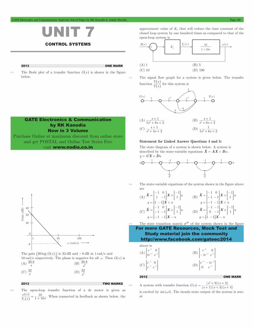


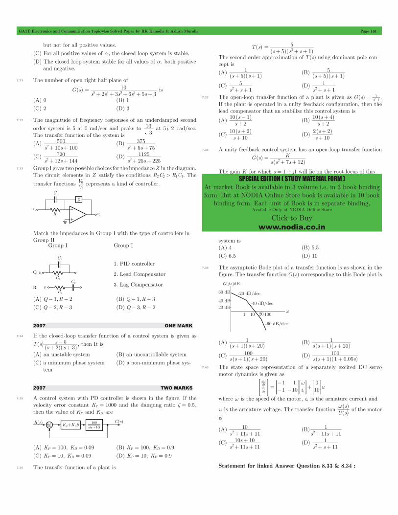
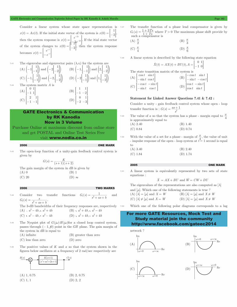


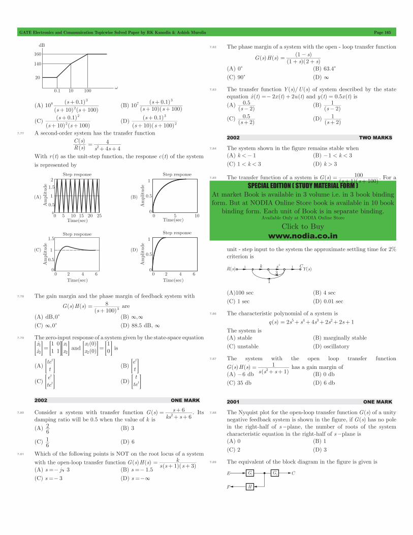
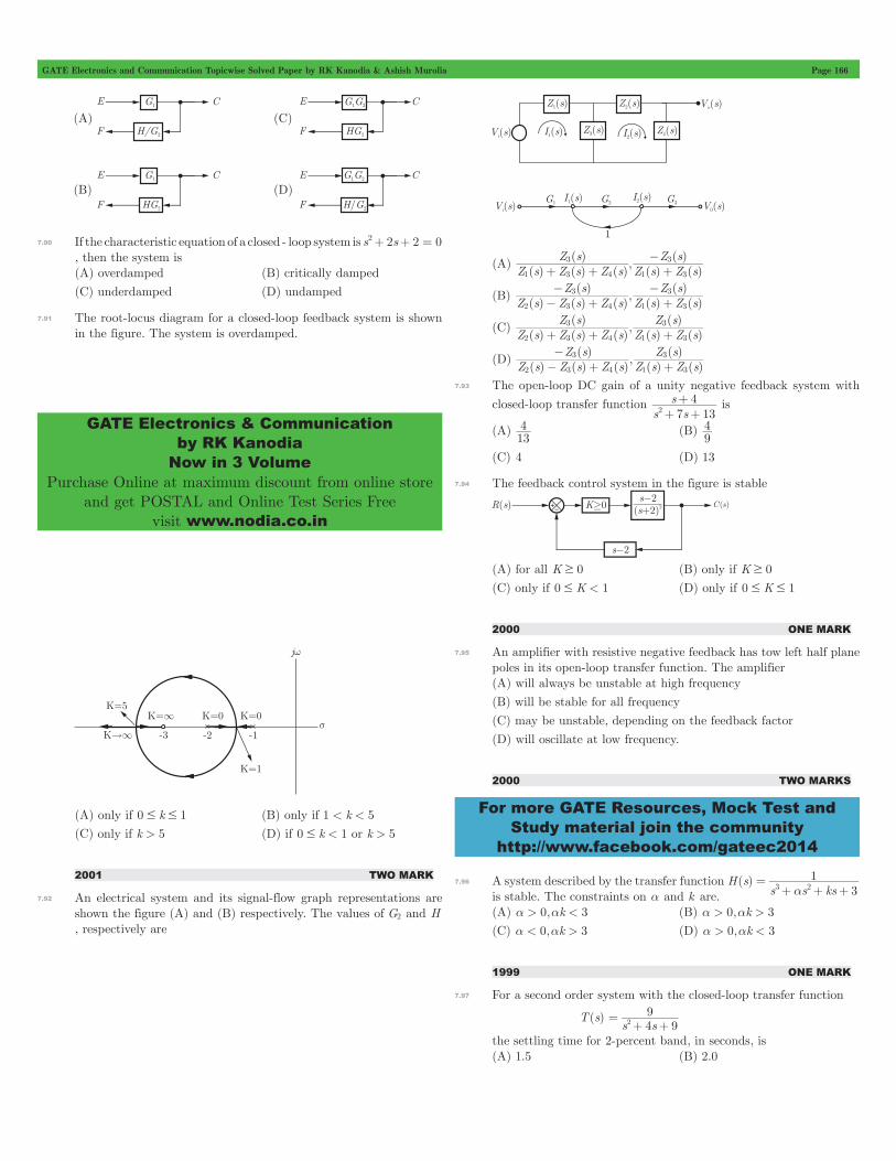


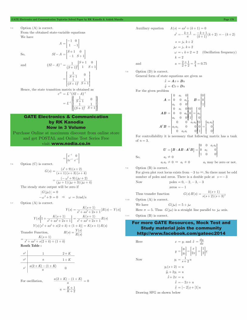


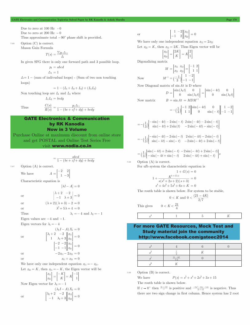

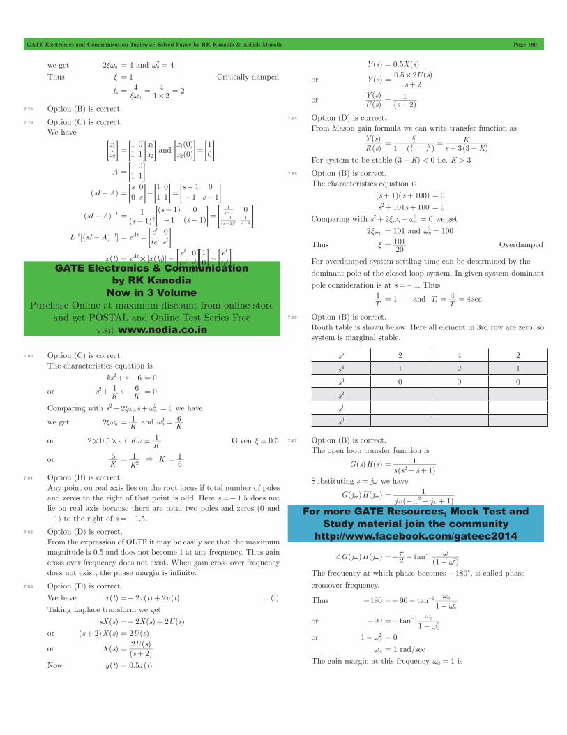
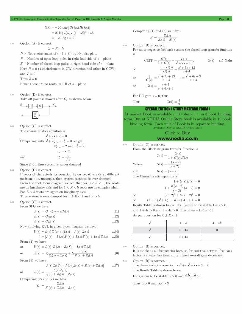
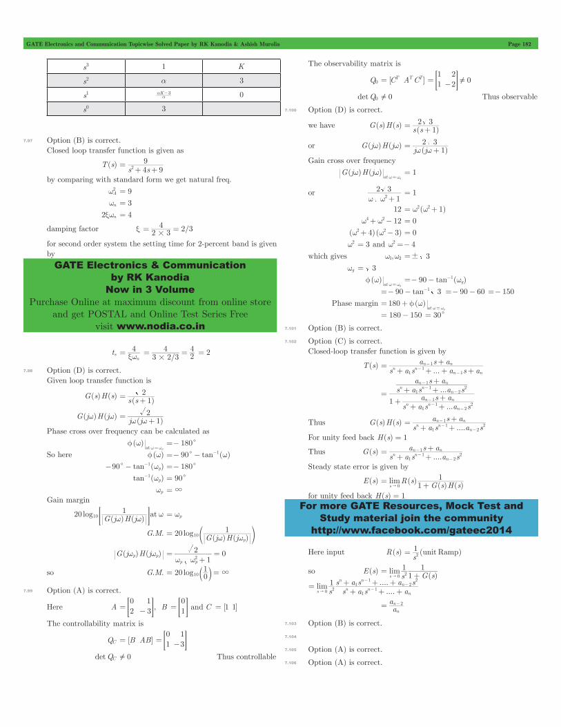


![Embedded Systems Chapter -7 Control Systemaakritsubedi9.com.np/files/Chapter 7 Embedded... · Embedded Systems Chapter -7 Control System. 7.Control System [3 Hrs.] 7.1 Open-loop and](https://static.documents.pub/doc/80x56/5f0a9eb27e708231d42c867b/embedded-systems-chapter-7-control-7-embedded-embedded-systems-chapter-7.jpg)


