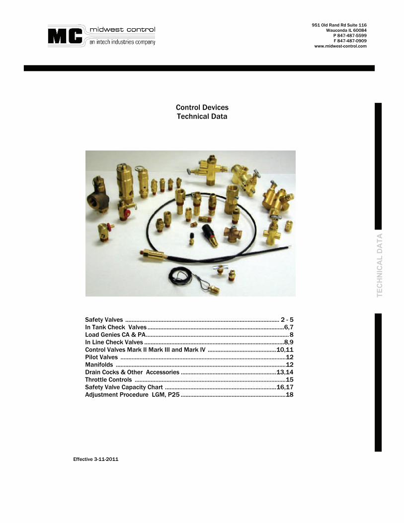
951 Old Rand Rd Suite 116 Wauconda IL 60084 P 847-487-5599 F 847-487-0909 www.midwest-control.com TECHNICAL DATA Control Devices Technical Data Effective 3-11-2011 Safety Valves ................................................................................................. 2 - 5 In Tank Check Valves ......................................................................................6,7 Load Genies CA & PA .......................................................................................... 8 In Line Check Valves ........................................................................................8,9 Control Valves Mark II Mark III and Mark IV ........................................... 10,11 Pilot Valves ........................................................................................................12 Manifolds ...........................................................................................................12 Drain Cocks & Other Accessories ............................................................ 13,14 Throttle Controls ...............................................................................................15 Safety Valve Capacity Chart ...................................................................... 16,17 Adjustment Procedure LGM, P25 ..................................................................18
Transcript
951 Old Rand Rd Suite 116 Wauconda IL 60084
P 847-487-5599 F 847-487-0909
www.midwest-control.com
TEC
HN
ICA
L D
ATA
Control Devices Technical Data
Effective 3-11-2011
Safety Valves ................................................................................................. 2 - 5 In Tank Check Valves ...................................................................................... 6,7 Load Genies CA & PA .......................................................................................... 8 In Line Check Valves ........................................................................................ 8,9 Control Valves Mark II Mark III and Mark IV ........................................... 10,11 Pilot Valves ........................................................................................................ 12 Manifolds ........................................................................................................... 12 Drain Cocks & Other Accessories ............................................................ 13,14 Throttle Controls ............................................................................................... 15 Safety Valve Capacity Chart ...................................................................... 16,17 Adjustment Procedure LGM, P25 .................................................................. 18
• Construction: All Brass with Stainless Steel Springs
• Unique O Ring Seal Ensures Valve is Bubble Tight To within 10% of Set Pressure
• Stamped with the UV and NB Symbols
• Available Sizes: 1/2”, 3/4”
3
951 Old Rand Rd Suite 116 Wauconda IL 60084
P 847-487-5599 F 847-487-0909
www.midwest-control.com
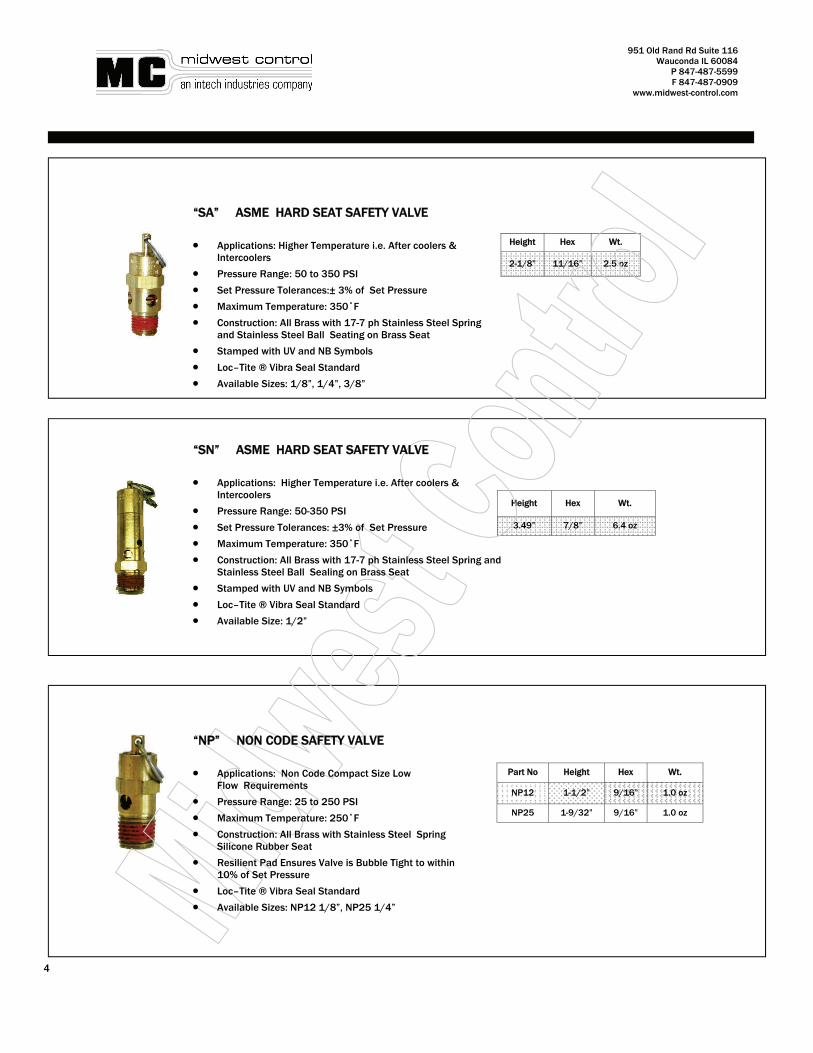
Height Hex Wt.
2-1/8” 11/16” 2.5 oz
Height Hex Wt.
3.49” 7/8” 6.4 oz
Part No Height Hex Wt.
NP12 1-1/2” 9/16” 1.0 oz
NP25 1-9/32” 9/16” 1.0 oz
“SN” ASME HARD SEAT SAFETY VALVE • Applications: Higher Temperature i.e. After coolers & Intercoolers
• Pressure Range: 50-350 PSI
• Set Pressure Tolerances: ±3% of Set Pressure
• Maximum Temperature: 350˚F
• Construction: All Brass with 17-7 ph Stainless Steel Spring and Stainless Steel Ball Sealing on Brass Seat
• Stamped with UV and NB Symbols
• Loc–Tite ® Vibra Seal Standard
• Available Size: 1/2”
“NP” NON CODE SAFETY VALVE • Applications: Non Code Compact Size Low Flow Requirements
• Pressure Range: 25 to 250 PSI
• Maximum Temperature: 250˚F
• Construction: All Brass with Stainless Steel Spring Silicone Rubber Seat
• Resilient Pad Ensures Valve is Bubble Tight to within 10% of Set Pressure
• Loc–Tite ® Vibra Seal Standard
• Available Sizes: NP12 1/8”, NP25 1/4”
“SA” ASME HARD SEAT SAFETY VALVE • Applications: Higher Temperature i.e. After coolers & Intercoolers
• Pressure Range: 50 to 350 PSI
• Set Pressure Tolerances:± 3% of Set Pressure
• Maximum Temperature: 350˚F
• Construction: All Brass with 17-7 ph Stainless Steel Spring and Stainless Steel Ball Seating on Brass Seat
• Stamped with UV and NB Symbols
• Loc–Tite ® Vibra Seal Standard
• Available Sizes: 1/8”, 1/4”, 3/8”
4
951 Old Rand Rd Suite 116 Wauconda IL 60084
P 847-487-5599 F 847-487-0909
www.midwest-control.com
TEC
HN
ICA
L D
ATA
Part No. PSI Range
NC25-001 Adjustable 25—50
NC25-002 Adjustable 51-100
NC25-003 Adjustable 101-150
NC25-004 Adjustable 151-200
“NC” NON CODE SAFETY VALVE • Applications: Non Code Safety Valve
• Field Adjustable
• Knurled Thumbscrew & Jam Nut Make Adjustments Easy & Repeatable
• Pressure Range: 25 to 200 PSI
• Maximum Temperature: 250˚F
• Construction: All Brass with Zinc Plated Music Wire Spring and Silicone Rubber Seal
• Loc–Tite ® Vibra Seal Standard
• Available Size: 1/4”
Height Hex Wt.
1-5/8” 9/16” 1.5 oz
5
For Higher Capacity Safety Valves Check Out Our
Conbraco and Kunkle Safety Valve Products
951 Old Rand Rd Suite 116 Wauconda IL 60084
P 847-487-5599 F 847-487-0909
www.midwest-control.com
Model Hex Dim (A) Dim (B)
Max Flow Rate
Wt. (oz)
F5050T 7/8
2-11/16 1-3/8 20 SCFM
F7575T 2-7/16 3.5
Part NO. HEX (In)
Dim (A) (In)
Dim (B) (In)
Max Flow Rate
Wt (oz)
P3838T 3/16 2 1-1/8 12 SCFM 3
P3850T 7/8 2-3/4 1-7/8 20 SCFM 3.8
P5050T 1 3 1-7/8 20 SCFM 5.5
P5075T 1-1/8 3-1/2 2-1/2 30 SCFM 6.5
P7575T 1-3/16 3-1/4 2-1/4 30 SCFM 7.2
P7510T 1-5/16 3-1/2 2-1/2 60 SCFM 11.4
P1010T 1-1/2 3-7/8 2-5/8 60 SCFM 12.5
P1212T 1-7/8 4-7/16 3-1/4 130 SCFM 17.5
P1515T 2-1/4 4-1/2 3-1/2 150 SCFM 30
P7515T 2-1/4 4-1/2 3-1/2 150 SCFM 24
FPT Inlet (In)
3/8
3/8
1/2
1/2
3/4
3/4
3/4
1
1-1/4
1-1/2
MPT Outlet
(In)
3/8
1/2
1/2
3/4
3/4
1
1-1/2
1
1-1/4
1-1/2
B A
• Maximum Pressure: 450 PSI
• Maximum Temperature: 400˚F
• 1/8” Tapped Port is Standard
• Construction: One Piece Brass Body Stainless Steel Springs Glass Filled Fluoropolymer Poppets for Long Term Reliability
• 8 Discharge Holes for Quiet Operation
• Can be Disassembled for Cleaning & Repair (See Price List for Spare Parts)
• Valves are 100% Tested for Backflow Leakage Performance
• Loc–Tite ® Vibra Seal Standard
SUPER CHEK® IN TANK CHECK VALVES “ P” SERIES (Female Pipe Inlet)
• Construction: One Piece Brass Body Stainless Steel Springs Glass Filled Fluoropolymer Poppets For Long Term Reliability
• 8 Discharge Holes for Quiet Operation
• Can be Disassembled for Cleaning & Repair
• Valves are 100% Tested for Backflow Leakage Performance
• Maximum Pressure: 450 PSI
• Maximum Temperature: 400˚ F
• 1/8” Tapped Port is Standard
• Loc–Tite ® Vibra Seal Standard
• See Price List for Repair Parts
SUPER CHEK® IN TANK CHECK VALVES “F” SERIES (Flared Fitting)
6
951 Old Rand Rd Suite 116 Wauconda IL 60084
P 847-487-5599 F 847-487-0909
www.midwest-control.com
TEC
HN
ICA
L D
ATA
Model Hex (In)
Dim (A) (In)
Dim (B) (In)
Max Flow Rate
Wt. (oz)
C3838 11/16 1-7/8 1-3/16 12 SCFM 1.5
C3850T 7/8 2-7/8 1-7/8 20 SCFM 4.2
C5038TA 11/16 2-1/4 1-3/16 12 SCFM 1.5
C5050T 7/8 2-7/8 1-7/8 20 SCFM 4.2
C7550T 7/8 2-7/8 1-7/8 20 SCFM 4.2
C7575T 1-1/8 3-1/2 2-3/8 30 SCFM 7.4
C7510T 1-5/16 3-3/4 2-5/8 60 SCFM 11.5
MPT Outlet
(In)
3/8
1/2
3/8
1/2
1/2
3/4
1
Tube Inlet (In)
3/8
3/8
1/2
1/2
3/4
3/4
3/4
SUPER CHEK® IN TANK CHECK VALVES “C” SERIES ( Compression Fitting)
COMPRESSION FITTING INLET ‘C’ SERIES
B A
• Construction: One Piece Brass Body Stainless Steel Springs Glass Filled Fluoro-polymer Poppets for Long Term Reliability
• 8 Discharge Holes for Quiet Operation
• Can be Disassembled for Cleaning & Repair (See Price List for Repair Parts)
• Valves are 100% Tested for Backflow Leakage Performance
• Maximum Pressure: 450 PSI
• Maximum Temperature: 400˚ F
• 1/8” Tapped Port is Standard
• Loc–Tite ® Vibra Seal Standard
• See Price List for Repair Parts
7
8
951 Old Rand Rd Suite 116 Wauconda IL 60084
P 847-487-5599 F 847-487-0909
www.midwest-control.com
Applications: Compressor Applications Where an In Tank check Valve Will Not Fit, the IC Valve Can Conveniently be Installed Right in the Discharge Line of the Compressor
• Created Around Super Chek® Design
• Construction: Brass Body Glass Filled Flouropolymer Poppets and Stainless Steel Springs for Long Life
• See Price List for Repair Parts
• A Plugged 1/8 NPT Unloader Port is Standard on the 1/2” & 3/4” Models
• Maximum Pressure 450 PSI
• Maximum Temperature: 400˚F
LOAD GENIES ‘CA’ & “PA’ • Size the Load Genie to Match the Compressor Flow
• As the Compressor Discharge Pressure Increases the Flow Capacity Decreases
• If the Flow Capacity Drops Below the Minimum Rated Flow of the Load Genie the Valve will React as if the Compressor has Stopped and Will Vent the Discharge Line . Size the Load Genie Towards the Maximum End of the Rated Flow Range
• Maximum Pressure 250 PSI
• Loc–Tite ® Vibra Seal Standard
Model Min/Max Flow
Hex (In)
Length (In)
Wt. (oz)
CA-6 1 TO 6 3/4 1-9/16 2
CA-12 3 TO 12 13/16 1-11/16 2.5
CA-24 8 TO 24 1 2-1/8 5
CA-48 15 TO 48 1-3/16 2-3/16 6
PA-6 1 TO 6 3/4 1-3/4 2.5
PA-12 3 TO 12 13/16 1-13/16 3
PA-24 8 TO 24 1 2-1/4 6
PA-48 15 TO 48 1-3/16 2-3/8 8
Outlet MPT (In)
1/4
3/8
1/2
3/4
1/4
3/8
1/2
3/4
Inlet Tube (In)
3/8
1/2
3/4
3/4
1/4
3/8
1/2
3/4
Part No.
FPT Inlet/ Outlet
(In)
Hex Length Recommended
Max Flow Rate
Wt. (oz)
IC50 1/2 1 2.82 20 7.0
IC75 3/4 1-1/4 3.54 30 13
*PA Inlet is FPT
IN LINE CHEK® VALVES VERTICAL “IC” SERIES
8
“CA”
“PA”
Hex (In)
Length (In)
Flow Rate
9/16 1.89 9 SCFM
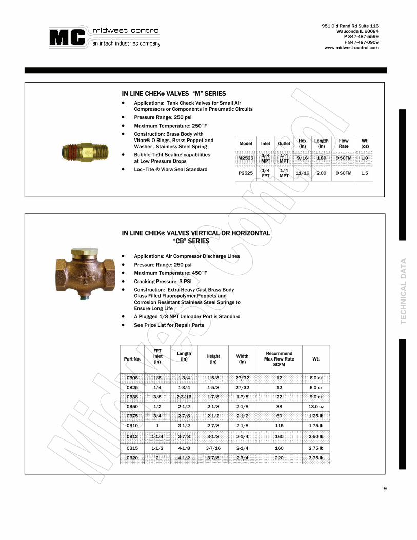
Model
M2525
Wt (oz)
1.0
P2525 11/16 2.00 9 SCFM 1.5
Inlet
1/4 MPT
1/4 FPT
Outlet
1/4 MPT
1/4 MPT
IN LINE CHEK® VALVES “M” SERIES • Applications: Tank Check Valves for Small Air Compressors or Components in Pneumatic Circuits
• Pressure Range: 250 psi
• Maximum Temperature: 250˚F
• Construction: Brass Body with Viton® O Rings, Brass Poppet and Washer , Stainless Steel Spring
• Bubble Tight Sealing capabilities at Low Pressure Drops
• Loc–Tite ® Vibra Seal Standard
951 Old Rand Rd Suite 116 Wauconda IL 60084
P 847-487-5599 F 847-487-0909
www.midwest-control.com
CB08 1-3/4 1-5/8 27/32 12 6.0 oz
CB25 1-3/4 1-5/8 27/32 12 6.0 oz
CB38 2-3/16 1-7/8 1-7/8 22 9.0 oz
CB50 2-1/2 2-1/8 2-1/8 38 13.0 oz
CB75 2-7/8 2-1/2 2-1/2 60 1.25 lb
CB10 3-1/2 2-7/8 2-1/8 115 1.75 lb
CB12 3-7/8 3-1/8 2-1/4 160 2.50 lb
CB15 4-1/8 3-7/16 2-1/4 160 2.75 lb
CB20 4-1/2 3-7/8 2-3/4 220 3.75 lb
Part No. Length
(In)
Height (In)
Width (In)
Recommend Max Flow Rate
SCFM Wt.
FPT Inlet (In)
1/8
1/4
3/8
1/2
3/4
1
1-1/4
1-1/2
2
TEC
HN
ICA
L D
ATA
IN LINE CHEK® VALVES VERTICAL OR HORIZONTAL “CB” SERIES
• Applications: Air Compressor Discharge Lines
• Pressure Range: 250 psi
• Maximum Temperature: 450˚F
• Cracking Pressure: 3 PSI
• Construction: Extra Heavy Cast Brass Body Glass Filled Fluoropolymer Poppets and Corrosion Resistant Stainless Steel Springs to Ensure Long Life
• A Plugged 1/8 NPT Unloader Port is Standard
• See Price List for Repair Parts
9
951 Old Rand Rd Suite 116 Wauconda IL 60084
P 847-487-5599 F 847-487-0909
www.midwest-control.com
LOAD GENIE MARK II LGM 20 SERIES
LOAD GENIE MARK III LGM 30 SERIES
A
D
B
C
• Application: Self Contained Unloading Valve Can Be Used Wherever a Continuous Run Air Compressor Is Required
• Combines All Components Required for Continuous Run Compressors: Pilot Valve, Vent Valve and Check Valve
• Eliminates the Need for Built in Head Unloaders
• Easy Installation: Install the Mark II in the Discharge Line Between the Compressor and the Air Receiver
• Factory Preset Cut In : Cut Out: Pressure (Standard) 95 – 115 (Optional High Pressure) 145 - 175) Minimum Cut In: 60 PSI Maximum Cut Out: 250 PSI Can be Field Adjusted
• Tapped & Plugged 1/8” Port for Throttle Control of a Gas Engine
• 1/8” NPT Tapped Port for Pressure Switch Unloader Valve and Vent Port Muffler
• A Toggle Unloading Lever for One Hand Warm Up Control
• Suitable for compressor Up to 30 SCFM
• Equipped with M20053 3/8” Muffler
• Optional Inlet and Outlet Ports Available— Consult Price List
10
A
D
C
B
LOAD GENIE MARK IV LGM 40 SERIES
951 Old Rand Rd Suite 116 Wauconda IL 60084
P 847-487-5599 F 847-487-0909
www.midwest-control.com
T
ECH
NIC
AL
DA
TA
A B
Model No. Dimensions
(A) Dimensions
(B)
Dimensions (C)
Dimensions (D)
LGM-20 3.87 1.43 .81 4.31
LGM-30 3.28 1.65 2.10 2.21
LGM-40 4.07 2.41
11
AUXILIARY UNLOADER (COLD START) CS SERIES
• Application: Bleeds Air From the Compressor Head During the First Few revolu-tions, Reducing Motor Starting Torque .
• Typical Applications are Oil Lubed Pumps that are Subject to Low Temperatures and Low Starting Voltages, i.e. a Contractor Unit that May Sit Outside Overnight and be Connected to a Long Extension Cord.
• Construction: Brass Piston and Body Stainless Steel Spring and Flurocarbon O Ring
• Available Sizes: 1/8”, 1/4”
• Application: Self Contained Unloading Valve Can Be Used Wherever a Continuous Run Air Compressor Is Required
• Combines All Components Required for Continuous Run Compressors: Pilot Valve, Vent Valve and Check Valve
• Eliminates the Need for Built in Head Unloaders
• Easy Installation: Install the Mark IV into the Receiver and Attach the Compressor Discharge Line to the Valve Inlet
• Compact Design Incorporates Both a Straight (LGM40A) & Optional 90 Degree Inlet (LGM40C) Flow Design
• Factory Preset Cut- In: Cut- Out: Pressure (Standard) 95 – 115 (Optional High Pressure) 145 - 175) Minimum Cut- In: 60 PSI Maximum Cut- Out: 250 PSI Can be Field Adjusted
• Tapped & Plugged 1/8” Port for Throttle Control of a Gas Engine
• 1/8” NPT Tapped Port for Pressure Switch Unloader Valve and Vent Port Muffler
• A Toggle Unloading Lever for One Hand Warm Up Control
• Suitable for compressor Up to 30 SCFM
• Equipped with M20053 3/8” Muffler
• Optional Inlet and Outlet Ports Available— Consult Price List
951 Old Rand Rd Suite 116 Wauconda IL 60084
P 847-487-5599 F 847-487-0909
www.midwest-control.com
Inlet Male
Outlet Female
Gauge Port Hex OAL Wt.
(oz)
1/2 1/4 1/4 7/8 1.84 4.8
AIR COMPRESSOR MANIFOLDS “ ACM” SERIES
• Applications: Suitable for Compressors 3 Hp & Smaller
• Features Built In Shut Off Valve & Safety Valve
• Includes Pressure Switch Mount & Tank Pressure Gauge Port which Allows All Control & Outlet Functions to be
Connected to the 1/2 NPT Tank Port
• Stock Pressure for Safety Valve 125,135,150
• Loc-Tite ® Vibra Seal Standard
CARRY TANK MANIFOLDS “CTM” SERIES
• Includes a Tank Filler Valve into the Built In Shut Off Valve
• Mates to a Typical Tire Chuck for Easy Tank Pressurization
• Safety Valve is Factory Preset at 150 PSI
• Includes Tank Pressure Gauge Port
• Construction: Brass Body & Components, Stainless Steel Springs, Nitrile O Rings & Silicone Rubber Safety Valve Seals
• Loc-Tite ® Vibra Seal Standard Inlet Male
Outlet Female
Gauge Port
Hex
1/2 1/4 1/4 7/8
OAL
1.84
Wt. (oz)
4.8
12
UNLOADER PILOT VALVES “P25” • Construction: Forged Brass Body,
Brass Adjustment Screws and Stainless Steel Ball and Spring
• Includes Mounting Boss Tapped with a 1/8-16 UNC Thread
• 1/4” NPT Inlet, 1/8” NPT Outlet.
• Unloading Sleeve for Gas Engine Warm Up
P25V Venting Unloader includes All the Features of the P25 Pilot Valve Plus a Vent Valve for Unloading the Compressor Discharge During Compressor Cut - Out
• Includes Toggle Unloader and Wire Mesh Inlet Screen
• Minimum Cut- In Pressure: 60 PSI
• Maximum Cut- Out Pressure: 250 PSI
• Maximum Temperature: 350˚F
• Field Adjustable
Part No. Cut In Cut Out FPT
Inlet Wrench
Flats HT Wt. (oz)
P25 95-115 95 115
1/4 3/4
3.78 6.4 P25 145-175 145 175
P25V 95-115 95 115 3.60
P25V 145-175 145 175 8
P25V
P25
951 Old Rand Rd Suite 116 Wauconda IL 60084
P 847-487-5599 F 847-487-0909
www.midwest-control.com
T
ECH
NIC
AL
DA
TA
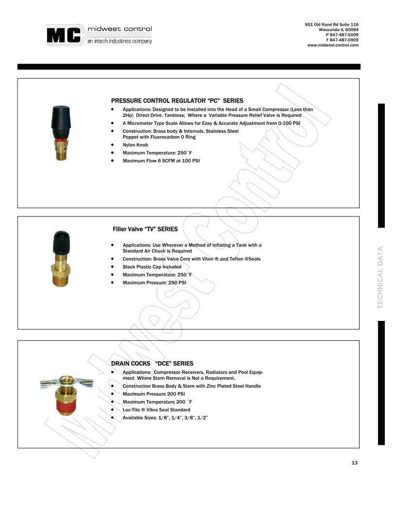
PRESSURE CONTROL REGULATOR “PC” SERIES • Applications: Designed to be Installed into the Head of a Small Compressor (Less than
2Hp) Direct Drive, Tankless; Where a Variable Pressure Relief Valve is Required
• A Micrometer Type Scale Allows for Easy & Accurate Adjustment from 0-100 PSI
• Construction: Brass body & Internals, Stainless Steel Poppet with Fluorocarbon O Ring
• Nylon Knob
• Maximum Temperature: 250˚F
• Maximum Flow 6 SCFM at 100 PSI
Filler Valve “TV” SERIES • Applications: Use Wherever a Method of Inflating a Tank with a
Standard Air Chuck is Required
• Construction: Brass Valve Core with Viton ® and Teflon ®Seals
• Black Plastic Cap Included
• Maximum Temperature: 250˚F
• Maximum Pressure: 250 PSI
DRAIN COCKS “DCE” SERIES • Applications: Compressor Receivers, Radiators and Pool Equip-
ment Where Stem Removal is Not a Requirement.
• Construction Brass Body & Stem with Zinc Plated Steel Handle
• Maximum Pressure 200 PSI
• Maximum Temperature 200 ˚F
• Loc-Tite ® Vibra Seal Standard
• Available Sizes: 1/8”, 1/4”, 3/8”, 1/2”
13
14
951 Old Rand Rd Suite 116 Wauconda IL 60084
P 847-487-5599 F 847-487-0909
www.midwest-control.com
DRAIN COCK with PULL CORD “DP” & “DM” SERIES
• Applications: Industrial and Automotive
• Brass Stem Tilts to Open the Valve at Minimum Pull Cord Force Stainless Steel Spring Returns the Stem to Positively Seal Against the Nitrile O Ring when Force on the Cord is Release
• Construction: Brass Body, Washer and Stem
• Maximum Pressure: 200 PSI
• Maximum Temperature: 200˚F
• Loc-Tite ® Vibra Seal Standard
DRAIN COCKS ‘DT’ SERIES
• Applications: Designed for Applications where the Traditional Drain cock is Easily Damaged
• Opens Easily and Closes with Minimum Effort
• Construction: Brass Body & Knurled Brass Stem
• Nitrile O Ring Ensures a Bubble Tight Seal
• Maximum Pressure: 200 PSI
• Maximum Temperature: 200˚F
• 1/4” Connection
• Loc-Tite ® Vibra Seal Standard
DRAIN COCKS (Con’t)
14
Part No. Cable Length
DP25 60”
DM25 36”
951 Old Rand Rd Suite 116 Wauconda IL 60084
P 847-487-5599 F 847-487-0909
www.midwest-control.com
TEC
HN
ICA
L D
ATA
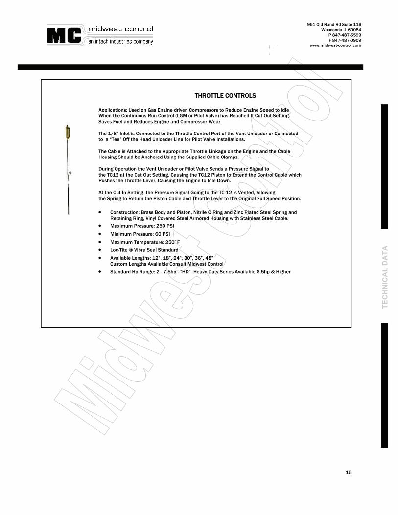
THROTTLE CONTROLS Applications: Used on Gas Engine driven Compressors to Reduce Engine Speed to Idle When the Continuous Run Control (LGM or Pilot Valve) has Reached It Cut Out Setting. Saves Fuel and Reduces Engine and Compressor Wear. The 1/8” Inlet is Connected to the Throttle Control Port of the Vent Unloader or Connected to a “Tee” Off the Head Unloader Line for Pilot Valve Installations. The Cable is Attached to the Appropriate Throttle Linkage on the Engine and the Cable Housing Should be Anchored Using the Supplied Cable Clamps. During Operation the Vent Unloader or Pilot Valve Sends a Pressure Signal to the TC12 at the Cut Out Setting. Causing the TC12 Piston to Extend the Control Cable which Pushes the Throttle Lever, Causing the Engine to Idle Down. At the Cut In Setting the Pressure Signal Going to the TC 12 is Vented, Allowing the Spring to Return the Piston Cable and Throttle Lever to the Original Full Speed Position.
• Construction: Brass Body and Piston, Nitrile O Ring and Zinc Plated Steel Spring and Retaining Ring, Vinyl Covered Steel Armored Housing with Stainless Steel Cable.
• Maximum Pressure: 250 PSI
• Minimum Pressure: 60 PSI
• Maximum Temperature: 250˚F
• Loc-Tite ® Vibra Seal Standard
• Available Lengths: 12”, 18”, 24”, 30”, 36”, 48” Custom Lengths Available Consult Midwest Control
• Standard Hp Range: 2 - 7.5hp, “HD” Heavy Duty Series Available 8.5hp & Higher
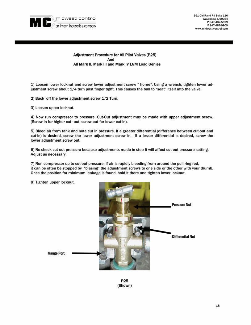
Adjustment Procedure for All Pilot Valves (P25) And All Mark II, Mark III and Mark IV LGM Load Genies
1) Loosen lower locknut and screw lower adjustment screw “ home”. Using a wrench, tighten lower ad-justment screw about 1/4 turn past finger tight. This causes the ball to “seat” itself into the valve. 2) Back off the lower adjustment screw 1/2 Turn. 3) Loosen upper locknut. 4) Now run compressor to pressure. Cut-Out adjustment may be made with upper adjustment screw. (Screw in for higher cut–out, screw out for lower cut-in). 5) Bleed air from tank and note cut in pressure. If a greater differential (difference between cut-out and cut-in) is desired, screw the lower adjustment screw in. If a lesser differential is desired, screw the lower adjustment screw out. 6) Re-check cut-out pressure because adjustments made in step 5 will affect cut-out pressure setting. Adjust as necessary. 7) Run compressor up to cut-out pressure. If air is rapidly bleeding from around the pull ring rod, it can be often be stopped by “biasing” the adjustment screws to one side or the other with your thumb. Once the position for minimum leakage is found, hold it there and tighten lower locknut. 8) Tighten upper locknut.