77
CONTROL DA220C5300 > > + P E - I 0 KL2334a INSTRUCTION MANUAL No. 402264 English FRANKL & KIRCHNER EFKA OF AMERICA INC. EFKA ELECTRONIC MOTORS GMBH & CO KG SINGAPORE PTE. LTD.
CONTROL DA220C5300
>>
+
P
E
-
I
0
KL2334a
INSTRUCTION MANUAL
No. 402264 English
FRANKL & KIRCHNER EFKA OF AMERICA INC. EFKA ELECTRONIC MOTORS GMBH & CO KG SINGAPORE PTE. LTD.

EFKA DA220C5300 3 CONTENTS Page
1 Range of Applications 7 1.1 Use in Accordance with Regulations 7 2 Scope of Supply 7 2.1 Special Accessories 8 3 Control Operation without Control Panel 8 3.1 Access Authorization upon Command Input 8 3.2 Programming the Code Number 9 3.3 Parameter Selection 10 3.3.1 Direct Selection 10 3.3.2 Changing Parameter Values 11 3.3.3 Parameter Selection with the +/- Keys 12 3.4 Changing All Parameter Values at the Operator Level 13 3.5 Function Switchover 13 3.6 Direct Input of Maximum Speed Limitation without Control Panel 13 3.7 Program Identification on the Control 14 4 Control Operation with Control Panel 15 4.1 Operation of the V810 Control Panel 15 4.1.1 Code Number Input on the V810 Control Panel 15 4.1.2 Parameter Input at the Operator Level on the V810 Control Panel 15 4.1.3 Parameter Input at the Technician/Supplier Level on the V810 Control Panel 16 4.2 V820 Control Panel Operation 16 4.2.1 Code Number Input on the V820 Control Panel 16 4.2.2 Parameter Input at the Operator Level on the V820 Control Panel 17 4.2.3 Parameter Input at the Technician/Supplier Level on the V820 Control Panel 17 4.3 Program Identification 18 4.4 Direct Input of Maximum Speed Limitation (DED) with Control Panel 18 4.4.1 Setting on the V810 Control Panel 18 4.4.2 Setting on the V820 Control Panel 18 4.5 Keys for Background Information (HIT) with V820 19 4.5.1 Example of HIT 19 4.5.2 Further Functions of the V810/V820 Control Panels 20 4.5.3 Special Functions of the V820 Control Panel 21 4.5.4 Disabling the Keys on the Control or on the Control Panels 21 4.6 Programming of Seams (TEACH IN) 22 4.6.1 Programming after Code Number Input 23 4.6.2 Programming without Code Number Input 23 4.6.3 Detailed Example 25 4.6.4 Inserting a Seam or Pattern 26 4.6.5 Deleting a Seam or Pattern 27 4.6.6 Execution (Pattern) Mode 27 4.6.7 Further Settings for TEACH IN 27 4.6.8 Disabling the Keys on Control Panel V820 with Activated TEACH IN 29 5 Putting into Service 30
6 Setting and Putting into Service with the Aid of the Fast Installation Routine (SIR) 30
7 Setting the Basic Functions 32 7.1 Direction of Motor Rotation 32 7.2 Use of a HSM001 Hall Sensor Module or IPG... Pulse Encoder 32 7.3 Selection of the Machine Series 33 7.3.1 Emergency Run Function If Machine Select Is Invalid 33
EFKA DA220C5300 4 CONTENTS Page 7.4 Transmission Ratio 33 7.5 Positioning Speed 34 7.6 Maximum Speed Compatible with the Sewing Machine 34 7.7 Maximum Speed 34 7.8 Positions 34 7.8.1 Setting the Reference Position (Parameter 270 = 0) 36 7.8.2 Setting the Positions on the Control (Parameter 270 = 0) 37 7.8.3 Setting the Positions on the V810 Control Panel (Parameter 270 = 0) 37 7.8.4 Setting the Positions on the V820 Control Panel (Parameter 270 = 0) 38 7.9 Display of the Signal and Stop Positions 38 7.10 Positioning Shift 39 7.11 Braking Characteristics 39 7.12 Braking Power at Standstill 39 7.13 Starting Characteristics 40 7.14 Actual Speed Display 40 8 Functions with or without Control Panel 41 8.1 Softstart 41 8.1.1 Softstart Speed 41 8.1.2 Softstart Stitches 41 8.2 Sewing Foot Lifting 41 8.3 Start Backtack 43 8.3.1 Speed n3 at the Seam Start 43 8.3.2 Stitch Counting for Start Backtack 43 8.3.3 Stitch Correction and Speed Release 44 8.3.4 Double Start Backtack 44 8.3.5 Single Start Backtack 44 8.4 End Backtack 44 8.4.1 Speed n4 at the Seam End 45 8.4.2 Stitch Counting for End Backtack 45 8.4.3 Stitch Correction and Last Stitch Backward 45 8.4.4 Double End Backtack 45 8.4.5 Single End Backtack 45 8.4.6 Backtack Synchronization 46 8.5 Start Ornamental Backtack 46 8.6 End Ornamental Backtack 46 8.7 Intermediate Backtack 47 8.8 Backtack Suppression/Recall 48 8.9 Holding Power of the Stitch Regulator Solenoid 48 8.10 Reverse Motor Rotation 48 8.11 Machine Run Blockage (Safety Switch) 49 8.11.1 Machine Start Blockage (Blockage 1 and 2) 49 8.11.2 Function “Machine Run Blockage” 1 (Safety Function) Parameter 283 = 1 49 8.11.3 Function “Machine Run Blockage” 2 (Control Function) Parameter 283 = 2 50 8.12 Bobbin Thread Monitor 50 8.12.1 Input Signals 51 8.12.2 Parameter 195 = 0 – No Bobbin Thread Monitor Function 51 8.12.3 Parameter 195 = 1 – Model 270 / No Stop / Sewing Foot Down after Seam End 51 8.12.4 Parameter 195 = 2 – Model 767, N291 / With Stop / Sewing Foot Up after Seam End 51 8.12.5 Parameter 195 = 3 – Model 767, N291 / With Stop / Sewing Foot Down after Seam
End 52 8.12.6 Parameter 195 = 4 – With Bobbin Thread Monitor Stitch Counting 52 8.13 Needle Cooling / Under-Edge Trimmer 52
EFKA DA220C5300 5 CONTENTS Page 8.14 Function Modules for Output A 52 8.14.1 Function Modules for Output A / No Function (Parameter 250 = 0) 53 8.14.2 Function Module for Output A / Switch Stitch Length (Pa. 250 = 1) 53 8.14.3 Function Module for Output A / Fullness Control with Speed Limitation (Pa. 250 = 2) 53 8.14.4 Function Module for Output A / Fullness Control without Speed Limitation (Pa. 250 = 3) 54 8.14.5 Function Module for Output A / Single Stitch with Short Stitch Length (Pa. 250 = 4) 54 8.14.6 Function Module for Output A / Lift/Lower Roller (Pa. 250 = 5) 55 8.14.7 Function Module for Output A / Lift/Lower Fabric Stop (Pa. 250 = 6) 56 8.14.8 Function Module for Output A / Second Thread Tension (Pa. 250 = 7) 56 8.14.9 Function Module for Output A / Manual Edge Trimmer (Pa. 250 = 8) 57 8.14.10 Function Module for Output A / Automatic Edge Trimmer (Pa. 250 = 9) 57 8.14.11 Function Module for Output A / Triflex Function (Pa. 250 = 10) 59 8.14.12 Function Module for Output A / High Lift for Walking Sewing Foot (Pa. 250 = 10) 59 8.14.13 Function Module for Output A / Sewing Foot Pressure Reduction (Pa. 250 = 12) 60 8.14.14 Function Module A / Handwheel Runs in the Direction of Rotation (Pa. 250 = 13) 60 8.14.15 Function Module A / Handwheel Runs in the Opposite Direction of Rotation (Pa. 250 = 13) 61 8.15 Function Modules for Output B 61 8.16 Speed Limitation 61 8.16.1 Speed Limitation DB2000/DB3000 61 8.16.2 Analog Speed Limitation 62 8.16.3 Analog Speed Limitation Speedomat 62 8.16.4 Setting the Speed Limitation Depending on High Lift with the V820 Control Panel 63 8.16.5 Setting the Speed Limitation Depending on High Lift with the V810 Control Panel 63 8.17 Thread Trimming Operation 64 8.17.1 Trimming Speed 64 8.17.2 Thread Trimmer 64 8.17.3 Thread Tension Release 65 8.17.4 Thread Wiper 65 8.17.5 Thread Clamp 65 8.18 Seam with Stitch Counting 65 8.18.1 Stitches for Stitch Counting 65 8.18.2 Stitch Counting Speed 66 8.18.3 Seam with Stitch Counting When Light Barrier Is On 66 8.19 Free Seam and Seam with Light Barrier 66 8.20 Light Barrier 67 8.20.1 Speed after Light Barrier Sensing 67 8.20.2 General Light Barrier Functions 67 8.20.3 Reflection Light Barrier LSM002 67 8.20.4 Automatic Start Controlled by Light Barrier 68 8.20.5 Light Barrier Filter for Knitted Fabrics 68 8.21 Needle Up/Down; Single Stitch 68 8.22 F1/F2 Function Key Assignment on the V810/V820 Control Panels 69 8.23 Signals A1 and A2 69 8.24 Signal Output Position 1 71 8.25 Signal Output Position 2 72 8.26 Signal Output 512 Impulses per Rotation 72 8.27 Actuator 72 8.28 Acoustic Signal 73 8.29 Master Reset 73

EFKA DA220C5300 6 CONTENTS Page
9 Signal Test 73 9.1 Signal Test Using the Incorporated Control Panel or the V810/V820 73 10 Error Displays 75
11 Operating Elements of the V810 Control Panel 78
12 Operating Elements of the V820 Control Panel 79

EFKA DA220C5300 7 1 Range of Applications The drive is suitable for lockstitch, machine models 271, 272, 273, 274, 275. Furthermore, stepping motor operation is possible with the SM210A control. See connection scheme in the List of Parameters. 1.1 Use in Accordance with Regulations The drive is not an independently operating machine, but is designed to be incorporated into other machinery. It must not be put into service until the machinery into which it is to be incorporated has been declared in conformity with the provisions of the EC Directive (Appendix II, paragraph B of the Directive 89/392/EEC and supplement 91/368/EEC). The drive has been developed and manufactured in accordance with the relevant EC standards: EN 60204-3-1:1990 Electrical equipment of industrial machines: Particular requirements for industrial sewing machines, sewing units and sewing systems. Operate the drive only in dry areas. 2 Scope of Supply
1 Direct current motor DC1500 1 Electronic control DA220C5300 - Power pack N201 1 Actuator EB301A 1 Set of standard accessories B158 consisting of: Plastic bag for B156 Documentation 1 Set of accessories Z54 consisting of: Pitman rod 400...700mm long Bracket for fastening EB3..
Note If there is no metallical contact between drive (motor) and machine head, the potential equalization cord supplied
with the unit is to be wired from the machine head to the terminal provided on the control box!
CAUTIONWhen selecting the installation site and the layout of the connecting cable, the Safety
Instructions in chapter 1 must be followed with no exceptions. Particular attention should be paid to maintaining the proper distance from moving
parts!

EFKA DA220C5300 8 2.1 Special Accessories
Control panel Variocontrol V810 - part no. 5970153 Control panel Variocontrol V820 - part no. 5970154 Reflection light barrier module LSM002 - part no. 6100031 Hall sensor module HSM001 - part no. 6100032 Pulse encoder IPG001 - part no. 6100033 EFKANET interface IF232-2, complete - part no. 7900068 Adapter cord for the connection of light barrier module and Hall sensor module - part no. 1113229 HSM001 or pulse encoder IPG001, or light barrier module, Hall sensor module HSM001 or pulse encoder IPG001 and EFKANET Actuating solenoid type EM1.. (for e. g. sewing foot lifting, backtacking, etc.) - see specification
“solenoids” for available models
Extension cable approx. 1000 mm long for commutation transmitter DC15.. - part no. 1113151 Extension cable approx. 1000 mm long for DC15.. line - part no. 1113150 Potential equalization cord 700 mm long, LIY 2.5 mm2, grey, with forked cable - part no. 1100313 brackets on both sides Foot control type FB302 with three pedals for standing operation, with approx. 1400 mm - part no. 4170025 connecting cable and plug Fitting piece for position transmitter - part no. 0300019 Knee switch type KN3 (pushbutton) with cord of approx. 950 mm length without plug - part no. 5870013 Undertable mounting kit for DC15.. - part no. 1113235 Sewing light transformer - please indicate line
voltage and sewing light voltage (6,3V or 12V)
9-contact SubminD male connector - part no. 0504135 9-contact SubminD male connector - part no. 0504136 Half-shell housing for 9-contact SubminD - part no. 0101523 37-pin SubminD male connector, complete - part no. 1112900 Single pins for 37-pin SubminD with strand of 5cm length - part no. 1112899
3 Control Operation without Control Panel 3.1 Access Authorization upon Command Input
In order to prevent unintentional changes of preset functions the command input is distributed at various levels. The following persons have access: - the supplier to the highest and all subordinate levels using a code number
- the technician to the next lower and all subordinate levels using a code number
- the operator to the lowest level without using a code number ACaCCallufruf
Call-up Supplier: Code number for control 311 or control panel 3112
Supplier Level 200 series of
parameter numbers
Technician: Code number for control 190 or control panel 1907
Technician Level 100 series of
parameter numbers
Operator Level

EFKA DA220C5300 9 3.2 Programming the Code Number
Note The parameter numbers in the illustrations below serve as examples and may not be available in all program versions.
In this case, the display shows the next higher parameter number. See List of Parameters. 1. Press the P key and turn power on 2. Press the >> key (1st digit blinks)
E0
I
1/KL2316
P
E
3. Press the + or – key to select 4. Press the >> key 5. Press the + or – key to select the 1st digit (2nd digit blinks) the 2nd digit Technician level Code no. 190 Supplier level Code no. 311
E
P
E
P
2/KL2317
E
P
6. Press the >> key 7. Press the + or – key to 8. Press the E key; the parameter (3rd digit blinks) select the 3rd digit number is displayed, which is indicated by points between the digits.
P
E
P
E
3/KL2318
P
EFKA DA220C5300 10
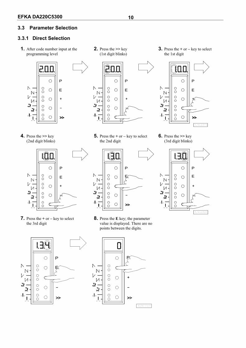
3.3 Parameter Selection 3.3.1 Direct Selection 1. After code number input at the 2. Press the >> key 3. Press the + or – key to select programming level (1st digit blinks) the 1st digit
P
E
P
E
4/KL2319
P
E
4. Press the >> key 5. Press the + or – key to select 6. Press the >> key (2nd digit blinks) the 2nd digit (3rd digit blinks)
P
E
P
E
5/KL2320
P
E
7. Press the + or – key to select 8. Press the E key; the parameter the 3rd digit value is displayed. There are no points between the digits.
P
E
6/KL2321
P

EFKA DA220C5300 11 3.3.2 Changing Parameter Values 1. Display after parameter value selection 2. Change the parameter value by pressing the + or - key
7/KL2322
P
E
P
E
Option 1 Press the E key. The next Press the P key. Exit programming. parameter number is displayed. The changed parameter values will be saved when you start sewing again!
8/KL2323
P
E
Option 2 Press the P key. The same Press the P key. Exit programming. parameter number is displayed. The changed parameter values will be saved when you start sewing again!
9/KL2324
E E
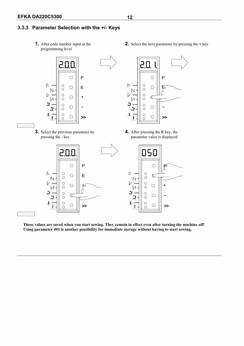
EFKA DA220C5300 12 3.3.3 Parameter Selection with the +/- Keys 1. After code number input at the 2. Select the next parameter by pressing the + key programming level
10/KL2325
P
E
P
E
3. Select the previous parameter by 4. After pressing the E key, the pressing the - key parameter value is displayed
11/KL2326
P
E
P
These values are saved when you start sewing. They remain in effect even after turning the machine off! Using parameter 401 is another possibility for immediate storage without having to start sewing.
EFKA DA220C5300 13 3.4 Changing All Parameter Values at the Operator Level
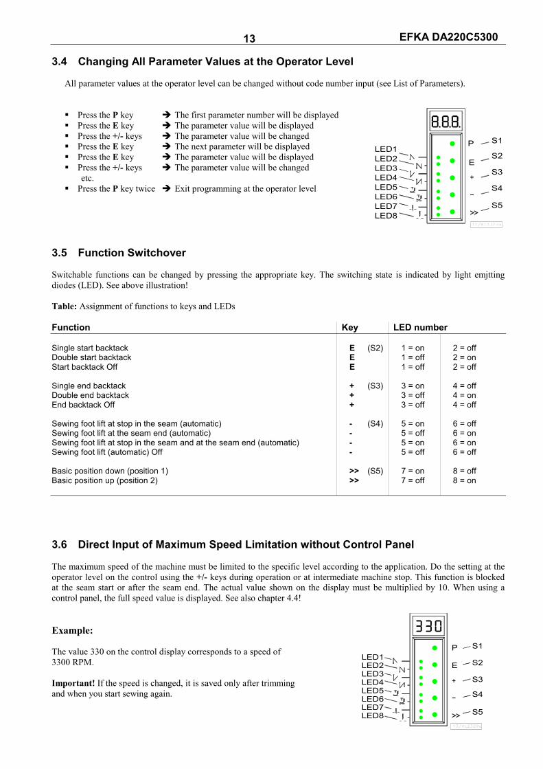
All parameter values at the operator level can be changed without code number input (see List of Parameters). Press the P key The first parameter number will be displayed Press the E key The parameter value will be displayed Press the +/- keys The parameter value will be changed Press the E key The next parameter will be displayed Press the E key The parameter value will be displayed Press the +/- keys The parameter value will be changed
etc. Press the P key twice Exit programming at the operator level
3.5 Function Switchover Switchable functions can be changed by pressing the appropriate key. The switching state is indicated by light emjtting diodes (LED). See above illustration! Table: Assignment of functions to keys and LEDs Function Key LED number Single start backtack E (S2) 1 = on 2 = off Double start backtack E 1 = off 2 = on Start backtack Off E 1 = off 2 = off Single end backtack + (S3) 3 = on 4 = off Double end backtack + 3 = off 4 = on End backtack Off + 3 = off 4 = off Sewing foot lift at stop in the seam (automatic) - (S4) 5 = on 6 = off Sewing foot lift at the seam end (automatic) - 5 = off 6 = on Sewing foot lift at stop in the seam and at the seam end (automatic) - 5 = on 6 = on Sewing foot lift (automatic) Off - 5 = off 6 = off Basic position down (position 1) >> (S5) 7 = on 8 = off Basic position up (position 2) >> 7 = off 8 = on 3.6 Direct Input of Maximum Speed Limitation without Control Panel The maximum speed of the machine must be limited to the specific level according to the application. Do the setting at the operator level on the control using the +/- keys during operation or at intermediate machine stop. This function is blocked at the seam start or after the seam end. The actual value shown on the display must be multiplied by 10. When using a control panel, the full speed value is displayed. See also chapter 4.4! Example: The value 330 on the control display corresponds to a speed of 3300 RPM. Important! If the speed is changed, it is saved only after trimming and when you start sewing again.
LED7LED8
LED1LED2LED3LED4LED5LED6
S1
S4
S3
S2
S5
12/KL2327a
P
E
LED3LED4LED5LED6LED7LED8
LED2LED1
S1
S5
S2
S3
S4
13/KL2328a
P
E

EFKA DA220C5300 14 3.7 Program Identification on the Control
Function without control panel Parameter
Program number, modification index and identification number display 179
After having selected parameter 179 (example), the following information is displayed in succession: 1. Select parameter 179. 2. Press the E key. 3. Press the >> key. Abbreviation Sr5 is displayed. The first 2 digits of the program number are displayed.
P
E
P
14/KL2329a
P
E
4. Press the E key. 5. Press the E key. 6. Press the E key. The second 2 digits of the The program modification The identification number program number are displayed. index is displayed. digits 1 and 2 are displayed.
P P P
15/KL2330a 7. Press the E key. 8. Press the E key. 9. Press the E key. The identification number The identification number The identification number digits 3 and 4 are displayed. digits 5 and 6 are displayed. digits 7 and 8 are displayed.
P P
17/KL2361
P
The routine is repeated after pressing the E key. Exit the routine after pressing the P key once. The next parameter number is displayed. Exit programming after pressing the P key. The drive is again ready for sewing.
EFKA DA220C5300 15 4 Control Operation with Control Panel
4.1 Operation of the V810 Control Panel
4.1.1 Code Number Input on the V810 Control Panel
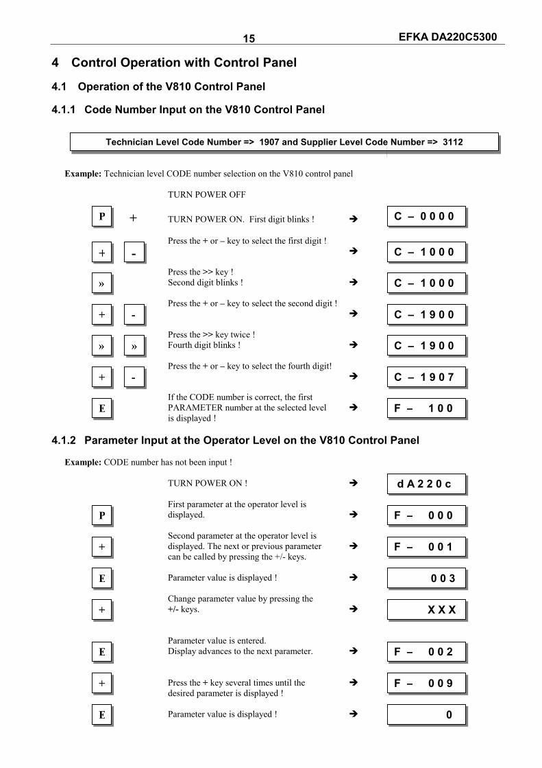
Example: Technician level CODE number selection on the V810 control panel TURN POWER OFF + TURN POWER ON. First digit blinks ! Press the + or – key to select the first digit ! Press the >> key ! Second digit blinks ! Press the + or – key to select the second digit ! Press the >> key twice ! Fourth digit blinks ! Press the + or – key to select the fourth digit! If the CODE number is correct, the first PARAMETER number at the selected level is displayed !
4.1.2 Parameter Input at the Operator Level on the V810 Control Panel Example: CODE number has not been input ! TURN POWER ON ! First parameter at the operator level is displayed. Second parameter at the operator level is displayed. The next or previous parameter can be called by pressing the +/- keys. Parameter value is displayed ! Change parameter value by pressing the +/- keys. Parameter value is entered. Display advances to the next parameter. Press the + key several times until the desired parameter is displayed ! Parameter value is displayed !
Technician Level Code Number => 1907 and Supplier Level Code Number => 3112
P C – 0 0 0 0
+ - C – 1 0 0 0
» C – 1 0 0 0
+ - C – 1 9 0 0
» » C – 1 9 0 0
+ - C – 1 9 0 7
E F – 1 0 0
d A 2 2 0 c
P F – 0 0 0
+ F – 0 0 1
E 0 0 3
+ X X X
E F – 0 0 2
+ F – 0 0 9
E 0
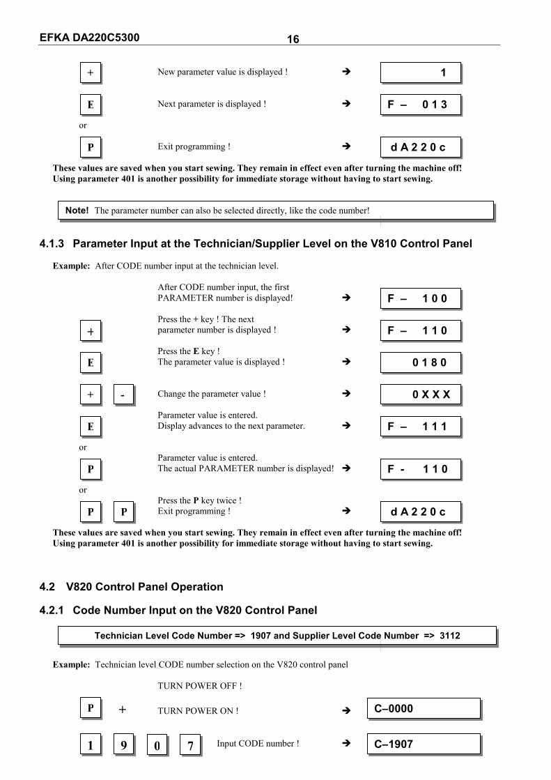
EFKA DA220C5300 16 New parameter value is displayed ! Next parameter is displayed ! or Exit programming ! These values are saved when you start sewing. They remain in effect even after turning the machine off! Using parameter 401 is another possibility for immediate storage without having to start sewing.
4.1.3 Parameter Input at the Technician/Supplier Level on the V810 Control Panel Example: After CODE number input at the technician level. After CODE number input, the first PARAMETER number is displayed! Press the + key ! The next parameter number is displayed ! Press the E key ! The parameter value is displayed ! Change the parameter value ! Parameter value is entered. Display advances to the next parameter. or Parameter value is entered. The actual PARAMETER number is displayed! or Press the P key twice ! Exit programming ! These values are saved when you start sewing. They remain in effect even after turning the machine off! Using parameter 401 is another possibility for immediate storage without having to start sewing.
4.2 V820 Control Panel Operation
4.2.1 Code Number Input on the V820 Control Panel
Example: Technician level CODE number selection on the V820 control panel TURN POWER OFF ! + TURN POWER ON ! Input CODE number !
+ 1
Note! The parameter number can also be selected directly, like the code number!
F – 1 0 0
+ F – 1 1 0
E 0 1 8 0
+ - 0 X X X
E F – 0 1 3
P d A 2 2 0 c
E F – 1 1 1
P F - 1 1 0
P P d A 2 2 0 c
Technician Level Code Number => 1907 and Supplier Level Code Number => 3112
P C–0000
1 9 C–1907 0 7
EFKA DA220C5300 17 If CODE number is incorrect, repeat input ! If CODE number is correct, the first PARAMETER number at the selected level is displayed.
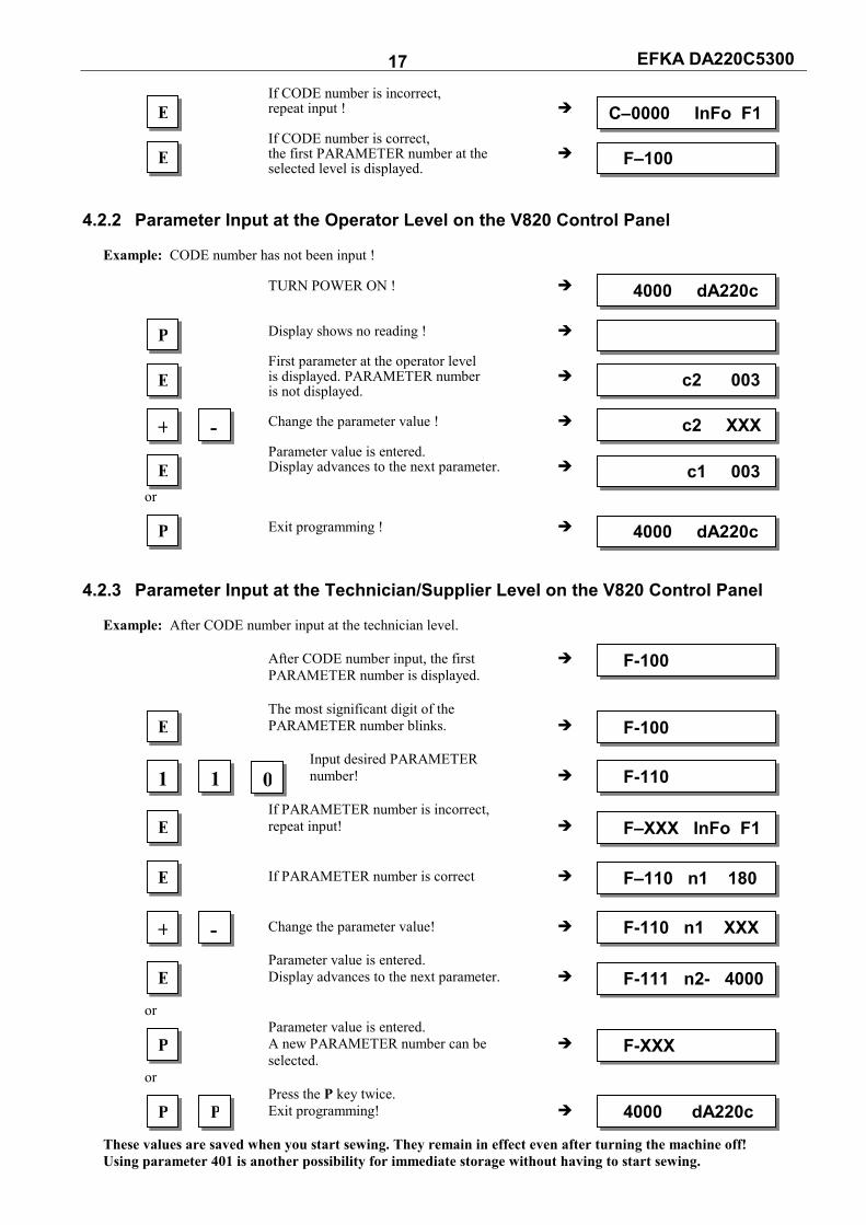
4.2.2 Parameter Input at the Operator Level on the V820 Control Panel Example: CODE number has not been input ! TURN POWER ON ! Display shows no reading ! First parameter at the operator level is displayed. PARAMETER number is not displayed. Change the parameter value ! Parameter value is entered. Display advances to the next parameter. or Exit programming !
4.2.3 Parameter Input at the Technician/Supplier Level on the V820 Control Panel Example: After CODE number input at the technician level. After CODE number input, the first PARAMETER number is displayed. The most significant digit of the PARAMETER number blinks. Input desired PARAMETER number! If PARAMETER number is incorrect, repeat input! If PARAMETER number is correct Change the parameter value! Parameter value is entered. Display advances to the next parameter. or Parameter value is entered. A new PARAMETER number can be selected. or Press the P key twice. Exit programming! These values are saved when you start sewing. They remain in effect even after turning the machine off! Using parameter 401 is another possibility for immediate storage without having to start sewing.
E C–0000 InFo F1
E F–100
4000 dA220c
E c2 003
E c1 003
P 4000 dA220c
P
+ - c2 XXX
F-100
E F-100
1 1 F-110 0
E F–XXX InFo F1
E F–110 n1 180
E F-111 n2- 4000
P F-XXX
+ - F-110 n1 XXX
P P 4000 dA220c

EFKA DA220C5300 18 4.3 Program Identification
Function with control panel Parameter
Program number, modification index and identification number display 179
Display example parameter 179 on the V810 control panel: Select parameter 179! Press the E key Sr5 [°] is displayed Press the >> key e. g. 5300A is displayed (Program number with index) Press the E key e. g. 010108 is displayed (1st part of identification number) Press the E key e. g. 15 is displayed (2nd part of identification number) Press the P key twice dA220c is displayed (Sewing process can be started) Display example parameter 179 on the V820 control panel: Select parameter 179! Press the E key F-179 Sr5 [°] is displayed Press the >> key e. g. 5300A is displayed (Program number with index) Press the E key e. g. 01010815 is displayed (Identification number) Press the P key twice dA220c is displayed (Sewing process can be started)
4.4 Direct Input of Maximum Speed Limitation (DED) with Control Panel The maximum speed of the machine must be limited to the specific level according to the application. Do the setting at the operator level using the +/- keys at any time. The actual value is shown on the display. The speed setting range is between parameter 111 (upper limit) and parameter 121 (lower limit). 4.4.1 Setting on the V810 Control Panel
Type designation is displayed Maximum speed is displayed (reading remains on for max. 5 seconds) Change the value; e. g. press the – key 8 times ! After approx. 5 seconds the display shows
4.4.2 Setting on the V820 Control Panel Actual display value, in the direct mode Maximum speed and type designation are displayed Change the maximum speed value; e. g. press the – key 8 times !
d A 2 2 0 c
+ 4 0 0 0
+ - 3 2 0 0
d A 2 2 0 c
4000 dA220c
+ - 3200 dA220c
NoteChanging the setting of the maximum speed limitation also affects the start backtack, end backtack and stitch
counting speeds.

EFKA DA220C5300 19
4.5 Keys for Background Information (HIT) with V820 (key assignment see figure on the last page) For fast operator information, the values of functions switched on using key 1, 2, 3, 4 or 9 are displayed on the control panel for approx. 3 seconds. During this time, the respective values can be varied directly by pressing the + or - key. 4.5.1 Example of HIT
Increase stitch-count seam section from 20 stitches to 25 stitches. Stitch-count function (key 2) is off.
Display after power on ↓↓↓↓ Press key 2 briefly ! Lefthand arrow and stitch-count function are on Press the + key ! Increase the number of stitches from 20 to 25 ! Display after approx. 3 seconds
Stitch-count function (key 2) is already on. Display after power on ↓↓↓↓ Press key 2 for at least 1 second! Lefthand arrow goes off momentarily; stitch-count function is on Press the + key ! Increase the number of stitches from 20 to 25 ! Display after approx. 3 seconds These values are saved when you start sewing. They remain in effect even after turning the machine off! Using parameter 401 is another possibility for immediate storage without having to start sewing.
Function key F Various parameters, even higher-level parameters, can be switched on or off by pressing the function key (key 9). The following functions may be assigned to the function key: 1. Softstart ON/OFF 2. Ornamental backtack ON/OFF 3. High lift for walking foot operational mode stored = ON / operational mode not stored = OFF 4. Needle cooling ON/OFF
NoteThe following functions are possible only with the V820 control panel!
4000 dA220c
2 Stc 020
+ Stc 025
4000 dA220c
2 Stc 020
+ Stc 025
4000 dA220c
4000 dA220c
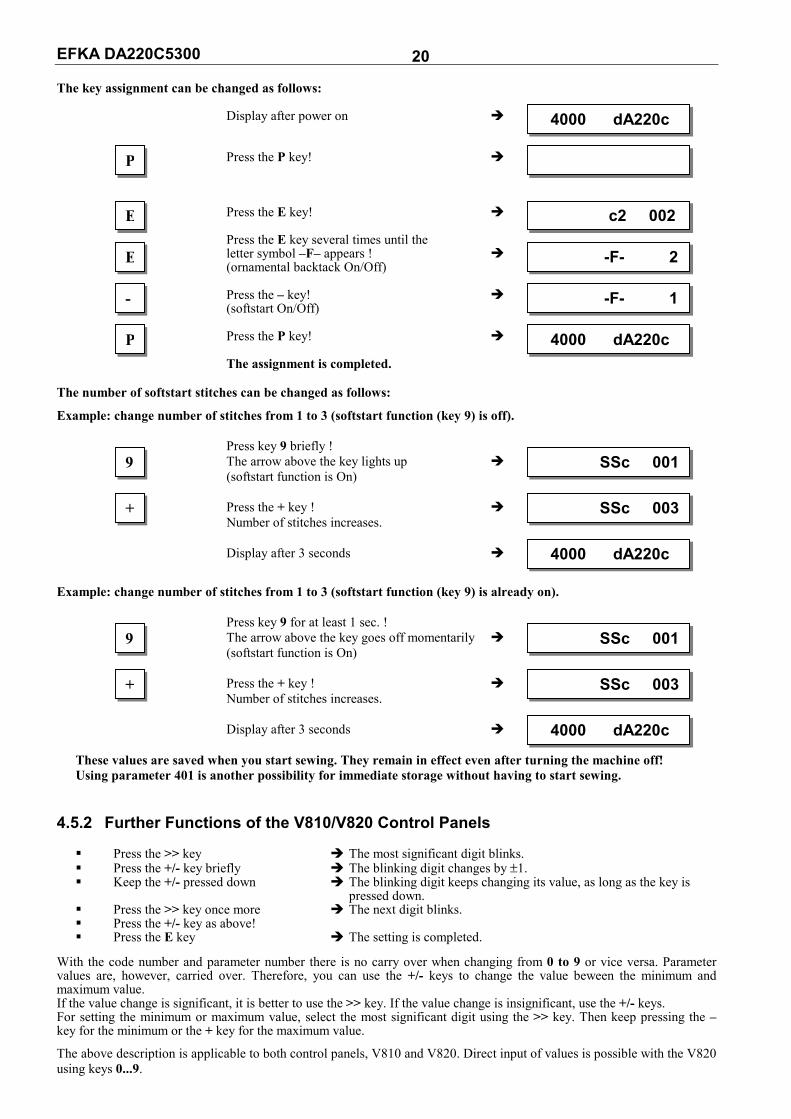
EFKA DA220C5300 20 The key assignment can be changed as follows:
Display after power on Press the P key! Press the E key! Press the E key several times until the letter symbol –F– appears ! (ornamental backtack On/Off) Press the – key! (softstart On/Off) Press the P key! The assignment is completed.
The number of softstart stitches can be changed as follows:
Example: change number of stitches from 1 to 3 (softstart function (key 9) is off). Press key 9 briefly ! The arrow above the key lights up (softstart function is On) Press the + key ! Number of stitches increases. Display after 3 seconds
Example: change number of stitches from 1 to 3 (softstart function (key 9) is already on). Press key 9 for at least 1 sec. ! The arrow above the key goes off momentarily (softstart function is On) Press the + key ! Number of stitches increases. Display after 3 seconds
These values are saved when you start sewing. They remain in effect even after turning the machine off! Using parameter 401 is another possibility for immediate storage without having to start sewing.
4.5.2 Further Functions of the V810/V820 Control Panels
Press the >> key The most significant digit blinks. Press the +/- key briefly The blinking digit changes by ±1. Keep the +/- pressed down The blinking digit keeps changing its value, as long as the key is
pressed down. Press the >> key once more The next digit blinks. Press the +/- key as above! Press the E key The setting is completed.
With the code number and parameter number there is no carry over when changing from 0 to 9 or vice versa. Parameter values are, however, carried over. Therefore, you can use the +/- keys to change the value beween the minimum and maximum value. If the value change is significant, it is better to use the >> key. If the value change is insignificant, use the +/- keys. For setting the minimum or maximum value, select the most significant digit using the >> key. Then keep pressing the – key for the minimum or the + key for the maximum value.
The above description is applicable to both control panels, V810 and V820. Direct input of values is possible with the V820 using keys 0...9.
P
E c2 002
4000 dA220c
E -F- 2
- -F- 1
P 4000 dA220c
9 SSc 001
+ SSc 003
4000 dA220c
9 SSc 001
+ SSc 003
4000 dA220c

EFKA DA220C5300 21 4.5.3 Special Functions of the V820 Control Panel The example below shows how minimum or maximum values can be set quickly.
Select parameter 200 Press the E key. The set value is displayed. Press key 0 three times. The minimum value is displayed. Press key 9 three times. The maximum value is displayed.
4.5.4 Disabling the Keys on the Control or on the Control Panels
Function with or without control panel Parameter
Disabling the P and E keys on the control panels and the P key on the control (EPE) 326 Disabling the + and – keys on the control panels (EPm) 327 Disabling the E, +, - and >> keys on the control (ob) 328
The P and E keys on the control panels can be enabled or disabled using parameter 326. On the control, only the P key can be disabled using this parameter. Parameter 326 = 0 Keys P and E are Off Parameter 326 = 1 Key P is On and key E is Off Parameter 326 = 2 Key P is Off and key E is On Parameter 326 = 3 Keys P and E are On
The + and – keys as well as the functions “direct input of maximum speed limitation” and “background information keys” can be enabled or disabled on the control panels and the function “direct input of maximum speed limitation” on the control using parameter 327. Parameter 327 = 0 Keys + and –are disabled (on the control, only the function “direct input of maximum speed
limitation” disabled). Parameter 327 = 1 Keys + and –are enabled
The E, +, - and >> keys on the control can be disabled using parameter 328. Parameter 328 = 0 Keys E, +, - and >> are disabled Parameter 328 = 1 Keys E, +, - and >> are enabled
Keys 1...4 on the V810 and 1...0 on the V820 can be disabled using one of the following parameters. Parameter 291 = 0 Keys 1...4 on control panel V810 are disabled. Parameter 292 = 0 Keys 1...0 on control panel V820 are disabled.
Keys F1 and F2 can be disabled using one of the following parameters. Parameter 293 = 0 Key F1 on the V810/V820 control panels is disabled. Parameter 294 = 0 Key F2 on the V810/V820 control panels is disabled.
Note Key disabling can be undone after power On upon inputting the code number!
2 0 F-200 0
E F–200 t1 050
0 0 F-200 t1 0000
9 9 F-200 t1 5009

EFKA DA220C5300 22 4.6 Programming of Seams (TEACH IN) A maximum of 40 patterns with a total of 40 seams can be programmed, i. e. 1 pattern with 40 seams each or 40
patterns with 1 seam each. In between, all combinations are possible. Programming is possible with or without code number. The functions “start backtack”, “end backtack”, “stitch counting”, “light barrier”, “thread trimmer”, “sewing foot lift”
and “needle positions” can be assigned individually to each seam. The functions of signals A1 and A2 can also be assigned to each seam, on condition that slide-in strip 6 has been
inserted into the V820 control panel and activated using the respective parameter 292. The stitches for start and end backtack and stitch counting as well as the compensating stitches for the light barrier
function can be programmed individually for each seam section. Several counted seam sections can be linked (key 9). Attention! The “TEACH IN“ function has been changed as compared to the 62 and 82 type series! Seams and/or patterns can be added by pressing the INSERT F1 key or erased by pressing the DELETE F2 key. Before programming new patterns and/or seams it is advisable to erase previously saved patterns and/or seams by pressing the DELETE F2 key according to chapter 4.6.5. If patterns or seams are to be inserted between existing ones, press the INSERT F1 key according to chapter 4.6.4. Example: 3 patterns are in the memory. Delete the 2nd pattern by pressing the DELETE F2 key. The 3rd pattern takes the place of the 2nd pattern. A new 2nd pattern can be installed by pressing the INSERT F1 key. The pattern in 2nd place will go back to being pattern no. 3. If patterns and/or seams are only to be added, proceed as described in the following chapters.
7
16
7
21
1 2
3 4
43
5 6
65
13 141211 15
B
E
DELETE
8 9
98
1 2
0
A10
INSERT F1
1817 19
P
+
6
KL2369
F2
-
1 = Single start backtack On (lefthand arrow) Double start backtack On (righthand arrow) Start backtack Off 2 = Counted seam forward On (lefthand arrow) Counted seam backward On (righthand arrow) Counted seam Off 3 = Light barrier uncovered/covered On (lefthand arrow) Light barrier covered/uncovered On (righthand arrow) Light barrier Off 4 = Single end backtack On (lefthand arrow) Double end backtack On (righthand arrow) End backtack Off 5 = Thread trimmer On (lefthand arrow) Thread wiper On (righthand arrow) Thread trimmer and thread wiper On (both arrows) Thread trimmer and thread wiper Off 6 = Sewing foot in the seam On (lefthand arrow) Sewing foot after seam end On (righthand arrow) Sewing foot in the seam and after seam end On (both arrows) Sewing foot Off 7 = Basic position down (lefthand arrow) Basic position up (righthand arrow)
8 = Signal A1 On (lefthand arrow) Signal A2 On (righthand arrow) Signal A1 and A2 On (both arrows) Signal A1 and A2 Off 9 = Switching from one seam to the next On (lefthand arrow) Switching from one seam to the next Off 10 = Programmed seams TEACH IN On (lefthand arrow) Programmed seams TEACH IN Off 11 = Program symbol 12 = Display of program number 13 = Seam symbol 14 = Display of seam number 15 = Symbol for number of stitches of a seam 16 = Display of number of stitches 17 = Light barrier symbol 18 = Display of light barrier compensating stitches 19 = Arrow for TEACH IN A = INSERT Insert seams or patterns B = DELETE Delete seams or patterns
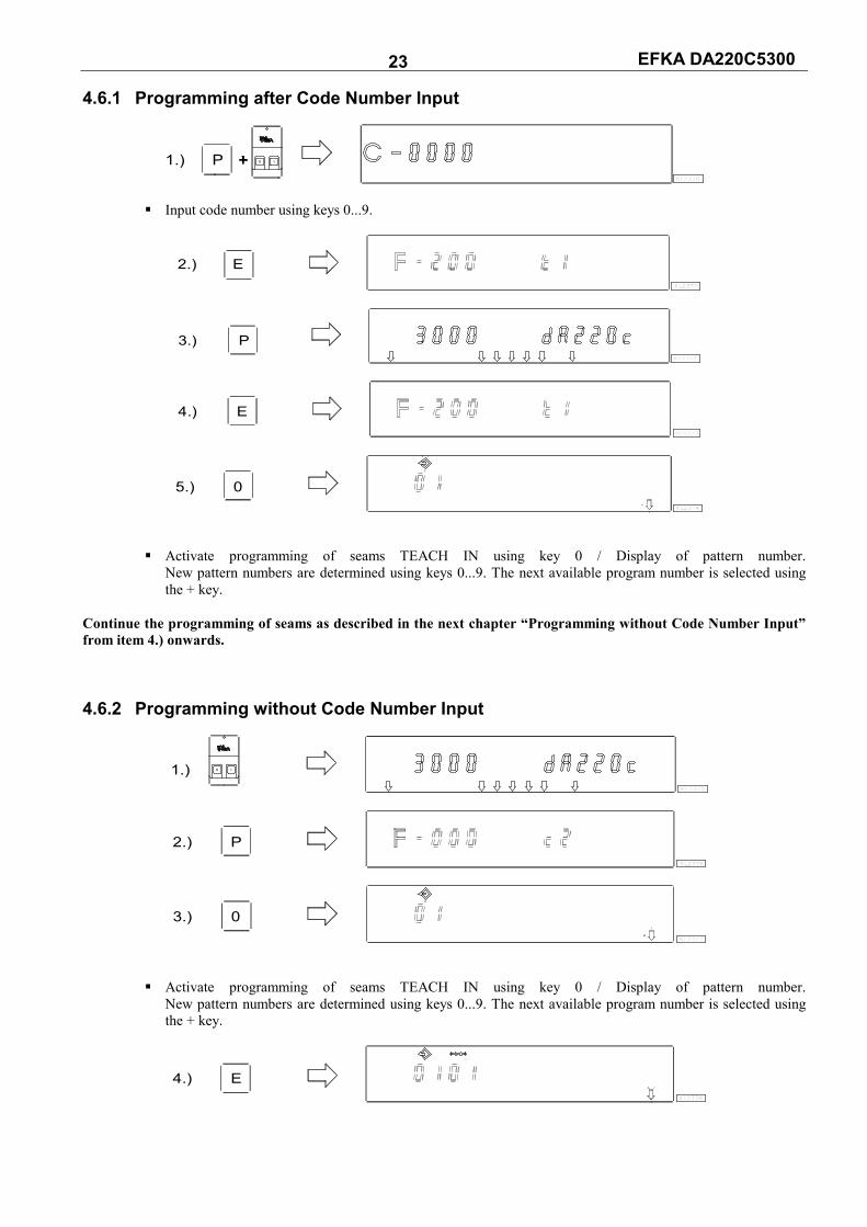
EFKA DA220C5300 23 4.6.1 Programming after Code Number Input
0 I1.) PKL2370
Input code number using keys 0...9.
E2.)KL2371
3.) PKL2372
4.) EKL2373
5.) 0KL2374
Activate programming of seams TEACH IN using key 0 / Display of pattern number. New pattern numbers are determined using keys 0...9. The next available program number is selected using the + key.
Continue the programming of seams as described in the next chapter “Programming without Code Number Input” from item 4.) onwards. 4.6.2 Programming without Code Number Input
1.) 0 I
KL2375
2.) PKL2376
3.) 0KL2377
Activate programming of seams TEACH IN using key 0 / Display of pattern number. New pattern numbers are determined using keys 0...9. The next available program number is selected using the + key.
4.) EKL2378

EFKA DA220C5300 24
Display of seam number
5.) EKL2379
6.) 1...
9KL2380
Enable all desired functions of the actual seam. as for ex. light barrier, by pressing keys 1...9.
7.) 2KL2381
After having enabled stitch counting using key 2, the number of stitches can be varied within 2 seconds. If
stitch counting has already been selected, press key 2 for approx. 2 seconds in order to vary the number of stitches. The arrow above key 2 switches briefly.
8.) + -KL2382
Press key + / - immediately.
9.)KL2383
If the + / - key has not been pressed within 2 seconds, the previously input number of stitches will be
displayed under the corresponding symbol (normal display).
10.) 3KL2384
After having enabled the light barrier using key 3, the number of light barrier compensating stitches can be
varied within 2 seconds. If the light barrier has already been selected, press key 3 for approx. 2 seconds in order to vary the number of light barrier compensating stitches. The arrow above key 3 switches briefly.
11.) -+KL2385
Press key + / - immediately.
12.)KL2386
If the + / - key has not been pressed within 2 seconds, the previously input number of stitches will be
displayed under the corresponding symbol (normal display). Change to the next seam by pressing the E key once. Exit programming of seams by pressing the P key twice. Start sewing in order to save the values.

EFKA DA220C5300 25 4.6.3 Detailed Example A seam 01 with double start backtack, stitch counting forward, position down, sewing foot up, a seam 02 with stitch counting forward, position down and a seam 03 with light barrier, double end backtack, thread trimming, position up, sewing foot up, are to be programmed (without code number input) under the next possible pattern number, e.g. 01. Turn power on Press key P Parameter 000 is displayed. Press key 0 Pattern number is displayed. The pattern symbol and the lefthand arrow above key 0 blink. Press key F2 Existing patterns will be deleted. If there is a 2nd pattern or more patterns, pattern number 01
must be inserted by pressing the INSERT F1 key. Set functions of seam 01: Press key E Seam number 01 is displayed. Press key E Functions can be programmed. Press key 1 The righthand arrow above key 1 indicates that the double start backtack is On. The start
backtack stitches must be input individually. Press key 2 The lefthand arrow above key 2 indicates that stitch counting forward is On. The number of
stitches can be varied as previously shown. Press key 6 The lefthand arrow above key 6 indicates that the sewing foot is automatically lifted in the
seam. Press key 7 The lefthand arrow above key 7 indicates that the needle is in the down position.
1 2 3 4 5 6 7
1 2
8 9 KL23870
Display of seam 01 after correct function input Set functions of seam 02: Press key E Seam number 02 is displayed. Press key 2 The lefthand arrow above key 2 indicates that stitch counting forward is On. The number of
stitches can be varied as previously shown. Press key 7 The lefthand arrow above key 7 indicates that the needle is in the down position.
1 2 3 4 5 6 7
1 2
8 9 0 KL2388
Display of seam 02 after correct function input

EFKA DA220C5300 26 Set functions of seam 03: Press key E Seam number 03 is displayed. Press key 3 The righthand arrow above key 3 indicates that the light barrier operates covered
uncovered. The light barrier compensating stitches can be varied as previously shown. Press key 4 The righthand arrow above key 4 indicates that the double end backtack is On. The end
backtack stitches must be input individually. Press key 5 Both arrows above key 5 indicate that thread trimmer and thread wiper are On. Press key 6 The lefthand arrow above key 6 indicates that the sewing foot is automatically lifted in the
seam. Press key 7 The lefthand arrow above key 7 indicates that the needle is in the up position.
721 3 4 5 6
1 2
8 9 KL23890
Display of seam 03 after correct function input Press the P key twice Exit programming of seams. Start sewing once The programmed data are saved. 4.6.4 Inserting a Seam or Pattern A pattern or seam can be inserted using the A “INSERT F1“ key, on condition that the symbol above the pattern or seam number is blinking during programming. Select the pattern or seam number where the new number is to be inserted. The symbol above the pattern or seam
number must be blinking. Proceed as shown in chapters “Programming with or without Code Number Input“. Press the A “INSERT F1“ key twice in brief succession. The new pattern or seam number will be inserted. All
subsequent numbers are automatically augmented by “1“. The following example shows how a seam is inserted before the existing seam.
KL2390
INSERT F1
KL2391
INSERT F1
KL2392
3 sec.
KL2393 Any desired function can now be assigned to the new seam.

EFKA DA220C5300 27 4.6.5 Deleting a Seam or Pattern A pattern or seam can be deleted using the B “DELETE F2“ key, on condition that the symbol above the pattern or seam number is blinking during programming. Select the pattern or seam number to be deletedc. The symbol above the pattern or seam number must be blinking.
Proceed as shown in chapters “Programming with or without Code Number Input“. Press the B “DELETE F2“ key twice in brief succession. The pattern or seam number will be deleted. All subsequent
numbers are automatically reduced by “1“. The following example shows how seam number 2 is deleted.
KL2394
DELETE F2
KL2395
DELETE F2
KL2396
3 sec.
KL2393 4.6.6 Execution (Pattern) Mode Press key 0 The programmed seams are enabled. Arrow above key 0 is On (but it does not blink). Press key +/- Selection of pattern. Only if several patterns have been programmed. Press key E If you do not wish to start with the first seam, select a different seam number. Press the E
key several times until the desired seam number is displayed. The drive can now be started by pressing the pedal, and the pattern can be executed. Press key 0 The programmed seams are disabled. Arrow above key 0 is Off. 4.6.7 Further Settings for TEACH IN
Functions Parameter
Seam suppression if 0 stitches are set (Std) 321
Parameter 321 = 0 Seam suppression disabled: i. e. if the light barrier is Off and stitch counting is set at 0 stitches, a
free seam will be performed. Parameter 321 = 1 Seam suppression enabled: i. e. if the light barrier is Off and stitch counting is set at 0 stitches, the
program switches to the next seam if the function is On. In case functions such as start of end backtack, thread trimmer, signals A1 / A2 are On, they will be performed before switching to the next seam.
Functions Parameter
Correction seam On/Off, seam or pattern interruption by thread trimmer (dkn) 322
Parameter 322 = 0 Correction seam disabled - The seam can be interrupted by pressing the pedal to pos. –2. The control switches automatically to
the next seam number. Parameter 322 = 1 Correction seam enabled - The seam can be interrupted by pressing the pedal to pos. –2 and thread trimming, and a correction seam (free seam) can be performed manually. - The correction seam can be completed by pressing the pedal to pos. –2 or by light barrier if it is On. Then the control switches automatically to the next seam number.

EFKA DA220C5300 28 Parameter 322 = 2 Seam or pattern interruption by thread trimming - The seam can be interrupted by pressing the pedal to pos. –2 and thread trimming, even if the
thread trimmer is Off. Then the program switches back to the first seam of the selected pattern. Sewing foot lift functions if TEACH IN is On: After power on the sewing foot is down even if sewing foot lifting after thread trimming is On on the control panel. the sewing foot can be lifted by pressing the pedal to pos. –1 or –2. If sewing foot lifting is On at the seam end (righthand arrow above key 6 on the V820 control panel On), the sewing foot is lifted after completing the seam. After having pressed the pedal to pos. 0 (neutral) the control switches to the next seam, and the sewing foot remains lifted until sewing is started. Whether or not the sewing foot is On or Off does not influence the seam end in the new seam. Automatic sewing foot lift with pedal forward at the seam end, if light barrier or stitch counting is On: Parameter 023 = 0 Automatic sewing foot lift Off Parameter 023 = 1 Automatic sewing foot lift On
Parameter 023 key 6 (righthand arrow) Sewing foot with pedal Sewing foot with forward after the seam pedal = 0 end 0 0 Off Off 1 0 On Off 1 1 On On 0 1 On On
Functions Parameter
Sewing foot lifted after power On, or as programmed (FLn) 323
This function is active only if TEACH IN is On. Parameter 323 = 0 After power On, the sewing foot lift function works as programmed. Parameter 323 = 1 The sewing foot is always lifted after power On, even if automatic sewing foot lift is not programmed.
Functions Parameter
TEACH IN On/Off (ti) 324
Using this parameter, TEACH IN can be enabled and disabled without control panel. However, TEACH IN programming is possible only with the V820 control panel. When the V820 is connected, TEACH IN is enabled and disabled using key 0.
Functions Parameter
Erasing all TEACH IN data (cti) 325
Input code number 3112 after power On Press the E key Input parameter 325 Press the E key Input 3112 Press the P key The display briefly shows “deleted“, and a short acoustic signal is issued. Press the P key All TEACH IN programs have been erased! Press the P key The sewing process is enabled again. If you press key 0 now, the display shows “no ProG“

EFKA DA220C5300 29 4.6.8 Disabling the Keys on Control Panel V820 with Activated TEACH IN Parameter 292 = 0 Keys 1...0 are disabled. Parameter 293 = 0 Key F1 is disabled. Parameter 294 = 0 Key F2 is disabled. Parameter 326 = 0 Keys P and E are Off (no programming, no switching from one seam to the next). Parameter 326 = 1 Key P is On and key E is Off (programming enabled; switching from one seam to the next disabled
using key E). Parameter 326 = 2 Key P is Off and key E is On (programming disabled; switching from one seam to the next enabled
using key E). Parameter 326 = 3 Keys P and E are On. Disable switching from one pattern to the next at the seam start using the + and – keys. Parameter 327 = 0 + and – keys are disabledf (switching from one pattern to the next impossible). Parameter 327 = 1 + and – keys are enabled.

EFKA DA220C5300 30 5 Putting into Service Before putting the control into service, the following must be ensured, checked and/or adjusted: The correct installation of the drive, position transmitter and accompanying devices, if necessary If necessary, the correct adjustment of the direction of motor rotation using parameter 161 The setting of the transmission ratio between motor shaft and machine shaft using parameter 272 The setting of the type of position sensor using parameter 270 If necessary, the setting of the number of angular degrees after the sensor position using parameter 171 The correct positioning speed using parameter 110 The correct maximum speed compatible with the sewing machine using parameter 111 The setting of the remaining relevant parameters Start sewing in order to save the set values 6 Setting and Putting into Service with the Aid of the Fast Installation
Routine (SIR) The Fast Installation Routine (SIR) passes through all parameters necessary for programming the functional sequence and the positions. Input parameter 500 Parameter for direction of motor rotation Parameter for transmission ratio Important! The transmission ratio should be determined and indicated as precisely as possible. Parameter for type of position sensor Parameter for position 1 Parameter for position 2 The values can be varied by pressing the +/- keys. When the parameter is displayed on the V810 control panel, press the E key once more for the value to be displayed. Exit the routine any time by pressing the P key once, and select a new parameter. Exit programming by pressing the P key twice, and the drive is ready for a new sewing operation.
F-272
End SIR
F-451
F-453
F-270
P
E
E
E
E
F-161
F-500
Code 3112
F-200
E
>
E
E
No
Yes
KL2518
>

EFKA DA220C5300 31
Functions Parameter
Call-up Fast Installation Routine SIR (Sir) 500
Setting on the V810 control panel: Input code number 3112! Press the E key The lowest parameter 2.0.0. appears at this level Select 500 Parameter 5.0.0. is displayed Press the E key Character [o] appears blinking Press the >> key Parameter 1.6.1. appears (direction of motor rotation) Press the E key Parameter value 1 appears Press the +/- key Parameter value can be changed Press the E key Parameter 2.7.2. appears (transmission ratio) Press the E key Parameter value 100 appears Press the +/- key Parameter value can be changed Press the E key Parameter 2.7.0. appears (type of position sensor) Press the E key Parameter value 0 appears Press the +/- key Parameter value can be changed Press the E key Parameter 4.5.1. appears (position 1 leading edge; position 1 trailing edge is automatically set at 60°) Press the E key Parameter value appears Press the +/- key Parameter value can be changed or turn the handwheel Set position after min. 1 rotation Press the E key Parameter 4.5.3. appears (position 2 leading edge; position 2 trailing edge is automatically set at 60°) Press the E key Parameter value appears Press the +/- key Parameter value can be changed or turn the handwheel Set position after min. 1 rotation Upon pressing the E key once more the program returns to parameter 290 Press the P key twice Exit SIR routine Setting on the V820 control panel: Input code number 3112! Press the E key The lowest parameter 2.0.0. appears at this level Select 500 Parameter 5.0.0. is displayed Press the E key Character [o] appears blinking Press the >> key Parameter 161 drE 1. appears (direction of motor rotation) Press the +/- key Parameter value can be changed Press the E key Parameter 272 trr 100 appears (transmission ratio) Press the +/- key Parameter value can be changed Press the E key Parameter 270 PGm 0 appears (type of position sensor) Press the +/- key Parameter value can be changed Press the E key Parameter 451 appears (position 1 leading edge; position 1 trailing edge is automatically set at 60°) Press the +/- key Parameter value can be changed or turn the handwheel Set position after min. 1 rotation Press the E key Parameter 453 appears (position 2 leading edge; position 2 trailing edge is automatically set at 60°) Press the +/- key Parameter value can be changed or turn the handwheel Set position after min. 1 rotation Upon pressing the E key once more the program returns to parameter 290 Press the P key twice Exit SIR routine

EFKA DA220C5300 32 7 Setting the Basic Functions 7.1 Direction of Motor Rotation
Function with or without control panel Parameter
Direction of motor rotation (drE) 161
Parameter 161 = 0 Clockwise motor rotation (look at the motor shaft) Parameter 161 = 1 Counterclockwise motor rotation
7.2 Use of a HSM001 Hall Sensor Module or IPG... Pulse Encoder Representation and installation of a HSM001 Hall sensor module or IPG... pulse encoder
Representation and installation of a HSM001 Hall sensor module or IPG... pulse encoder together with a LSM002 light barrier module using adapter cord no. 1113229
Operation with HSM001 Hall sensor module Operation with IPG... pulse encoder
- Get machine to the needle-up position. - Position bore for magnet such that the
magnet is located approx. 15° after the sensor in the sense of rotation.
- Get machine to the needle-up position. - Turn disk in the pulse encoder such that the
leading edge will be located approx. 15° after the sensor on the board.
ATTENTIONIf the motor is mounted differently, e. g. at a different angle or with gear, make sure
that the value set using parameter 161 corresponds to the direction of rotation.

EFKA DA220C5300 33 7.3 Selection of the Machine Series
Function with or without control panel Parameter
Display of the machine series (SEL) 280
The various machine models are specified by resistors. The following resistance values (tolerance ± 1%) are provided: Machine model = 271, 272, 273, 274, 275 = 100Ω 205 = 220Ω 069, 267, 268, 269, 4180, 4280 = 680Ω 367, 381, 382, 467, 767, 768 = 1000Ω
Select resistor is connected: The special functional sequences for this machine type and the various preset values are activated depending on the resistor identified. If such a select resistor is connected, it can be read out using parameter 280. The resistance value is displayed in Ohm directly on the control panel. The value cannot be varied.
Select resistor is not connected: If no select resistor is connected, Info A5 (emergency run) is displayed. After power On and inputting the code number, the select resistor value can be inputted using parameter 280. After that, press the P key twice, and Info A4 will be displayed. Power must be turned off. After powering on again, the preset values depending on the select for the respective machine model are set. 7.3.1 Emergency Run Function If Machine Select Is Invalid If the control cannot identify an admissible value for the machine select resistor, only emergency run functions are possible. All parameter settings and preset values are preserved.
Display: V810 V820 Emergency run function due to invalid machine select Available emergency run functions - Speed is limited to 1000 RPM
- Machine run blockage (safety switch) - Sewing foot lift when heeling the pedal back (-1, -2)
7.4 Transmission Ratio
Note The transmission ratio must always be input, becOffe only motors with integrated incremental transmitter will be used.
The transmission ratio should be determined and set as precisely as possible! The transmission ratio between motor shaft and shaft of the sewing machine head must be input, so that the set speeds of parameters 110...117 correspond to the sewing speeds.
Function with or without control panel Parameter
Transmission ratio between motor shaft and machine shaft (trr) 272
The transmission ratio can be selected within a range of 020...255 using parameter 272. Example: With a motor pulley diameter of 40mm and a sewing machine head pulley diameter of 80mm the value 50
can be calculated using the formula below. If the value 200 has been selected in parameter 272, it follows that the motor pulley is double the size of the sewing machine head pulley.
Motor pulley diameter Value of parameter 272 = ------------------------------------ x 100 Machine pulley diameter
InF A5InF A5

EFKA DA220C5300 34 7.5 Positioning Speed
Function with or without control panel Parameter
Positioning speed (n1) 110
The positioning speed can be set using parameter 110 on the control within a range of 70...390 RPM. 7.6 Maximum Speed Compatible with the Sewing Machine The maximum speed of the machine is determined by the selected pulley and by the following settings: Set the maximum speed using parameter 111 (n2) Set the maximum speed limitation to the specific level according to the application as described in chapter "Direct
Input of Maximum Speed Limitation (DED)". 7.7 Maximum Speed
Function with or without control panel Parameter
Maximum speed (n2) 111
Note See instruction manual of the sewing machine manufacturer for the maximum speed of the sewing machine.
Note
Select the pulley such that the motor runs at approx. 4000 RPM with max. number of stitches. When programming 3-digit or 4-digit parameter values on the control (without control panel), the 2-digit or 3-digit values displayed must be multiplied by 10. 7.8 Positions
Function with or without control panel Parameter
Setting the reference position (Sr1) 170 Setting the needle positions (Sr2) 171 Selection according to position sensor (PGm) 270 Transmission ratio between motor shaft and machine shaft (trr) 272
After setting parameter 270 at “1, 2, 3 or 4“ an angular degree must be selected using parameter 171, which determines the stop in position 2 or 1 after the sensor position. The transmission ratio must already have been input using parameter 272. Connection of a sensor e. g. light barrier to socket B18/7. The following settings are possible using parameter 270: Parameter 270 = 0 - The positions can be generated with the help of the transmitter incorporated in the motor and can be set using parameter 171. Parameter 270 = 1 - Setting the sensor to position 2.
- Position 1 is set according to the angular degree setting using parameter 171. - Start measuring from leading edge position 2. - 0V at input B18/7 (inside of the window) - +5V at input B18/7 (outside of the window)
Parameter 270 = 2 - Setting the sensor to position 2. - Position 1 is set according to the angular degree setting using parameter 171. - Start measuring from trailing edge position 2. - Input and output level as with setting “1“
Parameter 270 = 3 - Setting the sensor to position 1. - Position 2 is set according to the angular degree setting using parameter 171. - Start measuring from leading edge position 1. - Input and output level as with setting “1“
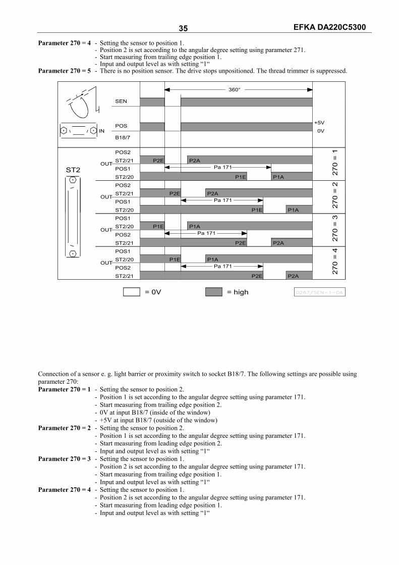
EFKA DA220C5300 35 Parameter 270 = 4 - Setting the sensor to position 1.
- Position 2 is set according to the angular degree setting using parameter 271. - Start measuring from trailing edge position 1. - Input and output level as with setting “1“
Parameter 270 = 5 - There is no position sensor. The drive stops unpositioned. The thread trimmer is suppressed.
P2A
P1A
= 0V
OUT
OUT
OUT
OUT
ST2
IN
POS1
ST2/21
POS2
POS2ST2/20POS1
ST2/21
ST2/20POS2
ST2/21POS1
ST2/20POS1ST2/20
P1E
P2E
P1E
POS
B18/7
ST2/21
POS2
SEN
P2E
= high 0267/SEN-1-DA
P1A
P2A
P1E
P2E
Pa 171
Pa 171P1A
Pa 171P2A
P2E
P1E
360°
Pa 171
270
= 1
P2A
P1A
270
= 3
270
= 4
270
= 2
+5V0V
Connection of a sensor e. g. light barrier or proximity switch to socket B18/7. The following settings are possible using parameter 270: Parameter 270 = 1 - Setting the sensor to position 2.
- Position 1 is set according to the angular degree setting using parameter 171. - Start measuring from trailing edge position 2. - 0V at input B18/7 (inside of the window) - +5V at input B18/7 (outside of the window)
Parameter 270 = 2 - Setting the sensor to position 2. - Position 1 is set according to the angular degree setting using parameter 171. - Start measuring from leading edge position 2. - Input and output level as with setting “1“
Parameter 270 = 3 - Setting the sensor to position 1. - Position 2 is set according to the angular degree setting using parameter 171. - Start measuring from trailing edge position 1. - Input and output level as with setting “1“
Parameter 270 = 4 - Setting the sensor to position 1. - Position 2 is set according to the angular degree setting using parameter 171. - Start measuring from leading edge position 1. - Input and output level as with setting “1“

EFKA DA220C5300 36
P2A
P1A
= 0V
OUT
OUT
OUT
OUT
ST2
IN
POS1
POS2ST2/21POS1ST2/20POS2ST2/21
ST2/20POS2ST2/21POS1ST2/20
ST2/20POS1
P1E
P1E
P2E
POS
B18/7
POS2ST2/21
SEN
P2E
= high 0267/SEN-2-DA
P1A
P2A
Pa 171
P1E
P2E
Pa 171
Pa 171
P1A
Pa 171
P2E
P1E
360°
P2A
270
= 1
P2A
P1A
270
= 3
270
= 4
270
= 2
+5V0V
OUT (position window) = npn transistor (emitter to 0V) is conductive. The width of position window cannot be adjusted. 7.8.1 Setting the Reference Position (Parameter 270 = 0) The angular positions necessary on the machine e.g. “needle down position“ or “thread lever up position“ are stored in the control. A reference position is needed in order to establish a relationship between position transmitter information and actual mechanical position.
The reference position must be set: for initial operation after replacing the motor after replacing the microprocessor Setting the reference position on the control Input code number and select parameter 170. Press the E key Display Sr1 Press the >> key Display P o (character o rotating)
Turn handwheel until rotating Display P character o goes off on the display.
Then position the notch on the handwheel Set machine reference point to marking F on the machine.
Press the P key once Actual parameter number is displayed Press the P key twice Exit programming at the technician level
Setting the reference position on the V810 control panel Input code number and select parameter 170. Press the E key Display Sr1 [o] Press the >> key Display PoS0 o (character o rotating)
Turn handwheel until rotating Display PoS0 character o goes off on the display.
Then position the notch on the handwheel Set machine reference point to marking F on the machine.
Press the P key once Actual parameter number is displayed Press the P key twice Exit programming at the technician level
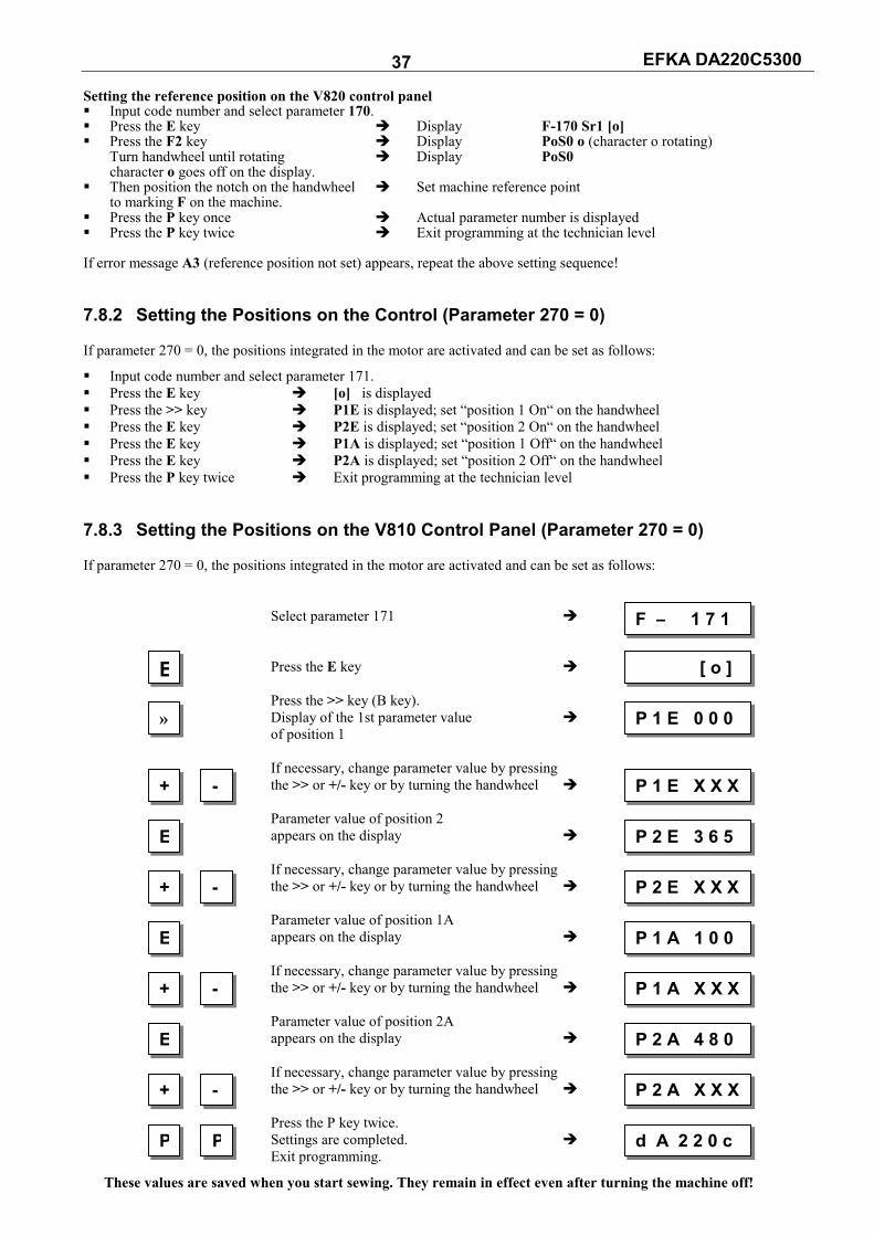
EFKA DA220C5300 37 Setting the reference position on the V820 control panel Input code number and select parameter 170. Press the E key Display F-170 Sr1 [o] Press the F2 key Display PoS0 o (character o rotating)
Turn handwheel until rotating Display PoS0 character o goes off on the display.
Then position the notch on the handwheel Set machine reference point to marking F on the machine.
Press the P key once Actual parameter number is displayed Press the P key twice Exit programming at the technician level If error message A3 (reference position not set) appears, repeat the above setting sequence! 7.8.2 Setting the Positions on the Control (Parameter 270 = 0) If parameter 270 = 0, the positions integrated in the motor are activated and can be set as follows:
Input code number and select parameter 171. Press the E key [o] is displayed Press the >> key P1E is displayed; set “position 1 On“ on the handwheel Press the E key P2E is displayed; set “position 2 On“ on the handwheel Press the E key P1A is displayed; set “position 1 Off“ on the handwheel Press the E key P2A is displayed; set “position 2 Off“ on the handwheel Press the P key twice Exit programming at the technician level 7.8.3 Setting the Positions on the V810 Control Panel (Parameter 270 = 0) If parameter 270 = 0, the positions integrated in the motor are activated and can be set as follows: Select parameter 171 Press the E key Press the >> key (B key). Display of the 1st parameter value of position 1 If necessary, change parameter value by pressing the >> or +/- key or by turning the handwheel Parameter value of position 2 appears on the display If necessary, change parameter value by pressing the >> or +/- key or by turning the handwheel Parameter value of position 1A appears on the display If necessary, change parameter value by pressing the >> or +/- key or by turning the handwheel Parameter value of position 2A appears on the display If necessary, change parameter value by pressing the >> or +/- key or by turning the handwheel Press the P key twice. Settings are completed. Exit programming.
These values are saved when you start sewing. They remain in effect even after turning the machine off!
F – 1 7 1
E [ o ]
» P 1 E 0 0 0
+ - P 1 E X X X
E P 2 E 3 6 5
P P d A 2 2 0 c
+ - P 2 E X X X
E P 1 A 1 0 0
+ - P 1 A X X X
E P 2 A 4 8 0
+ - P 2 A X X X
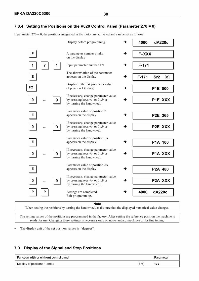
EFKA DA220C5300 38 7.8.4 Setting the Positions on the V820 Control Panel (Parameter 270 = 0) If parameter 270 = 0, the positions integrated in the motor are activated and can be set as follows: Display before programming A parameter number blinks on the display Input parameter number 171 The abbreviation of the parameter appears on the display Display of the 1st parameter value of position 1 (B key) If necessary, change parameter value ... by pressing keys +/- or 0...9 or by turning the handwheel. Parameter value of position 2 appears on the display If necessary, change parameter value ... by pressing keys +/- or 0...9 or by turning the handwheel. Parameter value of position 1A appears on the display If necessary, change parameter value ... by pressing keys +/- or 0...9 or by turning the handwheel. Parameter value of position 2A appears on the display If necessary, change parameter value ... by pressing keys +/- or 0...9 or by turning the handwheel. Settings are completed. Exit programming.
Note When setting the positions by turning the handwheel, make sure that the displayed numerical value changes.
The setting values of the positions are programmed in the factory. After setting the reference position the machine is
ready for use. Changing these settings is necessary only on non-standard machines or for fine tuning. The display unit of the set position values is “degrees“. 7.9 Display of the Signal and Stop Positions
Function with or without control panel Parameter
Display of positions 1 and 2 (Sr3) 172
1 7 F-171 1
E F-171 Sr2 [o]
0 P1E XXX9
4000 dA220c
P F–XXX
F2 P1E 000
0 P2E XXX9
E P2E 365
0 P1A XXX9
E P1A 100
P P 4000 dA220c
0 P2A XXX9
E P2A 480
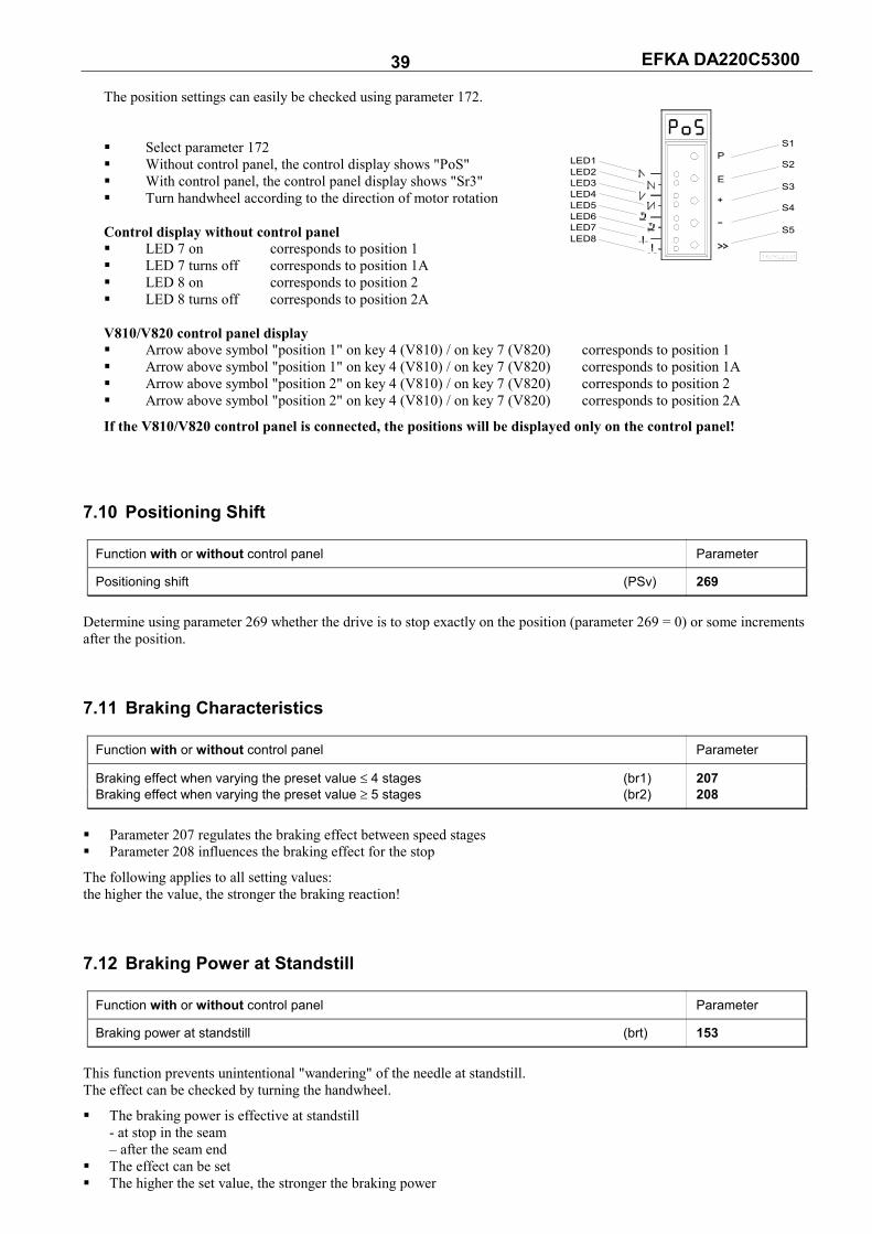
EFKA DA220C5300 39 The position settings can easily be checked using parameter 172. Select parameter 172 Without control panel, the control display shows "PoS" With control panel, the control panel display shows "Sr3" Turn handwheel according to the direction of motor rotation Control display without control panel LED 7 on corresponds to position 1 LED 7 turns off corresponds to position 1A LED 8 on corresponds to position 2 LED 8 turns off corresponds to position 2A V810/V820 control panel display Arrow above symbol "position 1" on key 4 (V810) / on key 7 (V820) corresponds to position 1 Arrow above symbol "position 1" on key 4 (V810) / on key 7 (V820) corresponds to position 1A Arrow above symbol "position 2" on key 4 (V810) / on key 7 (V820) corresponds to position 2 Arrow above symbol "position 2" on key 4 (V810) / on key 7 (V820) corresponds to position 2A
If the V810/V820 control panel is connected, the positions will be displayed only on the control panel! 7.10 Positioning Shift
Function with or without control panel Parameter
Positioning shift (PSv) 269
Determine using parameter 269 whether the drive is to stop exactly on the position (parameter 269 = 0) or some increments after the position. 7.11 Braking Characteristics
Function with or without control panel Parameter
Braking effect when varying the preset value ≤ 4 stages (br1) 207 Braking effect when varying the preset value ≥ 5 stages (br2) 208
Parameter 207 regulates the braking effect between speed stages Parameter 208 influences the braking effect for the stop
The following applies to all setting values: the higher the value, the stronger the braking reaction! 7.12 Braking Power at Standstill
Function with or without control panel Parameter
Braking power at standstill (brt) 153
This function prevents unintentional "wandering" of the needle at standstill. The effect can be checked by turning the handwheel.
The braking power is effective at standstill - at stop in the seam – after the seam end
The effect can be set The higher the set value, the stronger the braking power
16/KL2331
PLED1LED2LED3LED4LED5LED6LED7LED8
ES3
S4
S5
S2
S1
EFKA DA220C5300 40 7.13 Starting Characteristics
Function with or without control panel Parameter
Starting edge (ALF) 220
The drive acceleration dynamics can be adapted to the sewing machine characteristic (light/heavy). High setting value = high acceleration
With a high starting edge setting and, in addition, possibly high braking parameter values on a light machine, the characteristic may appear coarse. In this case, one should try to optimize the settings. 7.14 Actual Speed Display
Function with or without control panel Parameter
Actual speed display (nIS) 139
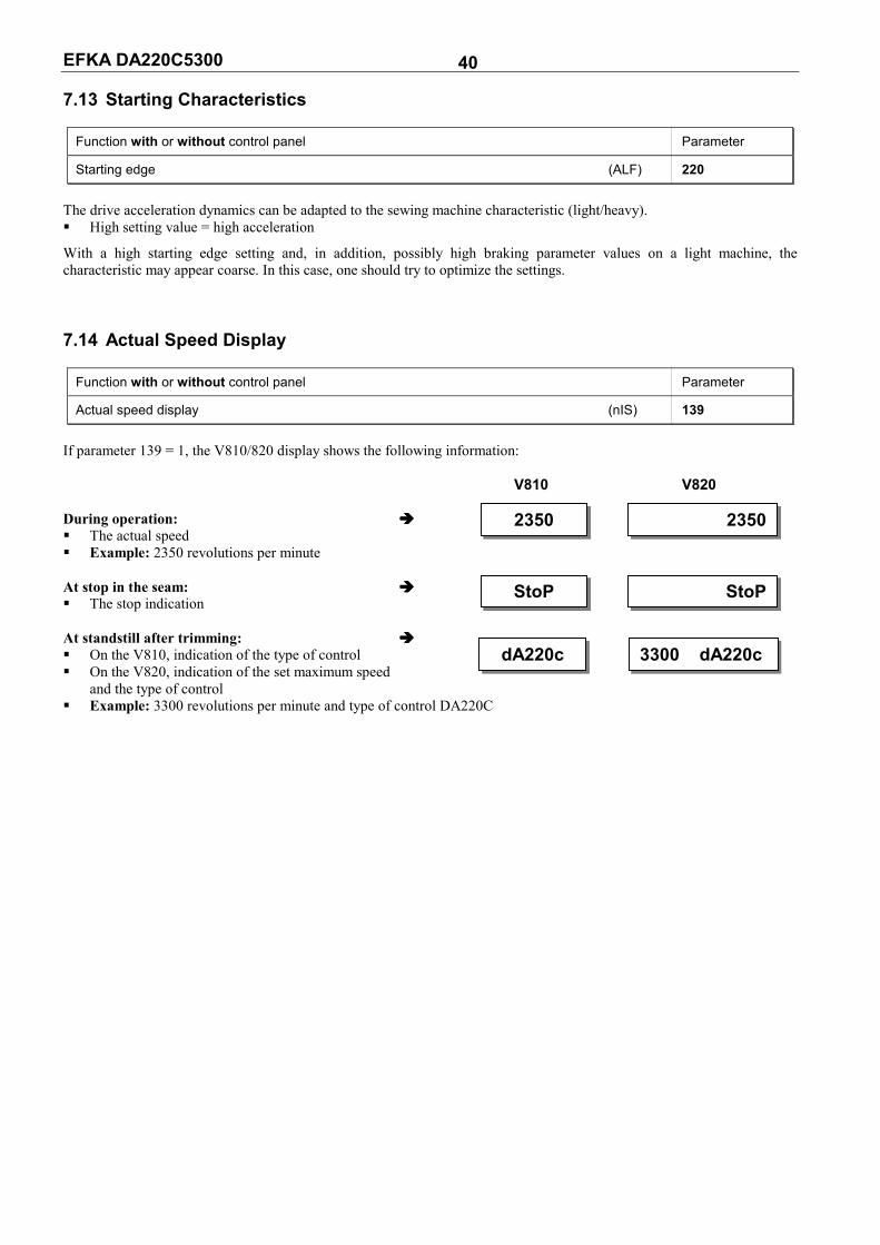
If parameter 139 = 1, the V810/820 display shows the following information: V810 V820 During operation: The actual speed Example: 2350 revolutions per minute At stop in the seam: The stop indication At standstill after trimming: On the V810, indication of the type of control On the V820, indication of the set maximum speed
and the type of control Example: 3300 revolutions per minute and type of control DA220C
23502350
StoPStoP
3300 dA220cdA220c

EFKA DA220C5300 41 8 Functions with or without Control Panel 8.1 Softstart
Function with or without control panel Parameter
Softstart On/Off (SSt) 134
Functions: after power on at the beginning of a new seam speed pedal controlled and limited to (n6) lower speed of a parallel function prevailing (e. g. start backtack, stitch counting) stitch counting synchronized to position 1 suspension with pedal in position 0 (neutral) interruption by full heelback (position -2) When using the V820 control panel, direct access by means of the function key (key 9) is possible!
Function with control panel Parameter
Softstart On/Off (-F-) 008 = 1
8.1.1 Softstart Speed
Function with or without control panel Parameter
Softstart speed (n6) 115
When programming 3-digit or 4-digit parameter values on the control, the 2-digit or 3-digit values displayed must be multiplied by 10. 8.1.2 Softstart Stitches
Function with or without control panel Parameter
Number of softstart stitches (SSc) 100
The letter symbols in parentheses ( ) are visible only if the V820 control panel is connected! 8.2 Sewing Foot Lifting
Function without control panel Control
Automatic in the seam lefthand LED above key On Key S4 Automatic after thread trimming righthand LED above key On Key S4
Function with control panel V810 V820
Automatic in the seam lefthand arrow above key On Key 3 Key 6 Automatic after thread trimming righthand arrow above key On Key 3 Key 6
EFKA DA220C5300 42
Function with or without control panel Parameter
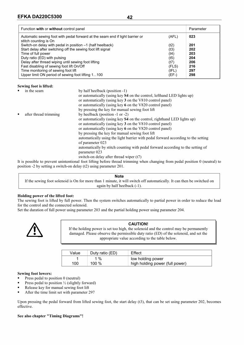
Automatic sewing foot with pedal forward at the seam end if light barrier or (AFL) 023 stitch counting is On Switch-on delay with pedal in position –1 (half heelback) (t2) 201 Start delay after switching off the sewing foot lift signal (t3) 202 Time of full power (t4) 203 Duty ratio (ED) with pulsing (t5) 204 Delay after thread wiping until sewing foot lifting (t7) 206 Fast disabling of sewing foot lift On/Off (FLS) 216 Time monitoring of sewing foot lift (tFL) 297 Upper limit ON period of sewing foot lifting 1...100 (EF-) 298
Sewing foot is lifted: in the seam by half heelback (position -1)
or automatically (using key S4 on the control, lefthand LED lights up) or automatically (using key 3 on the V810 control panel) or automatically (using key 6 on the V820 control panel) by pressing the key for manual sewing foot lift
after thread trimming by heelback (position -1 or -2) or automatically (using key S4 on the control, righthand LED lights up) or automatically (using key 3 on the V810 control panel) or automatically (using key 6 on the V820 control panel) by pressing the key for manual sewing foot lift automatically using the light barrier with pedal forward according to the setting of parameter 023 automatically by stitch counting with pedal forward according to the setting of parameter 023 switch-on delay after thread wiper (t7)
It is possible to prevent unintentional foot lifting before thread trimming when changing from pedal position 0 (neutral) to position -2 by setting a switch-on delay (t2) using parameter 201.
Note If the sewing foot solenoid is On for more than 1 minute, it will switch off automatically. It can then be switched on
again by half heelback (-1). Holding power of the lifted foot: The sewing foot is lifted by full power. Then the system switches automatically to partial power in order to reduce the load for the control and the connected solenoid. Set the duration of full power using parameter 203 and the partial holding power using parameter 204.
Value Duty ratio (ED) Effect 1 1 % low holding power 100 100 % high holding power (full power)
Sewing foot lowers: Press pedal to position 0 (neutral) Press pedal to position ½ (slightly forward) Release key for manual sewing foot lift After the time limit set with parameter 297 Upon pressing the pedal forward from lifted sewing foot, the start delay (t3), that can be set using parameter 202, becomes effective. See also chapter "Timing Diagrams"!
CAUTION!If the holding power is set too high, the solenoid and the control may be permanently damaged. Please observe the permissible duty ratio (ED) of the solenoid, and set the
appropriate value according to the table below.
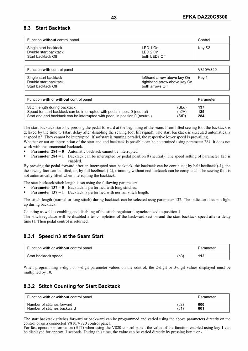
EFKA DA220C5300 43 8.3 Start Backtack
Function without control panel Control
Single start backtack LED 1 On Key S2 Double start backtack LED 2 On Start backtack Off both LEDs Off
Function with control panel V810/V820
Single start backtack lefthand arrow above key On Key 1 Double start backtack righthand arrow above key On Start backtack Off both arrows Off
Function with or without control panel Parameter
Stitch length during backtack (SLu) 137 Speed for start backtack can be interrupted with pedal in pos. 0 (neutral) (n2A) 125 Start and end backtack can be interrupted with pedal in position 0 (neutral) (StP) 284
The start backtack starts by pressing the pedal forward at the beginning of the seam. From lifted sewing foot the backtack is delayed by the time t3 (start delay after disabling the sewing foot lift signal). The start backtack is executed automatically at speed n3. They cannot be interrupted. If softstart is running parallel, the respective lower speed is prevailing. Whether or not an interruption of the start and end backtack is possible can be determined using parameter 284. It does not work with the ornamental backtack. Parameter 284 = 0 Automatic backtack cannot be interrupted Parameter 284 = 1 Backtack can be interrupted by pedal position 0 (neutral). The speed setting of parameter 125 is
enabled. By pressing the pedal forward after an interrupted start backtack, the backtack can be continued; by half heelback (-1), the the sewing foot can be lifted, or, by full heelback (-2), trimming without end backtack can be completed. The sewing foot is not automatically lifted when interrupting the backtack.
The start backtack stitch length is set using the following parameter: Parameter 137 = 0 Backtack is performed with long stitches. Parameter 137 = 1 Backtack is performed with normal stitch length.
The stitch length (normal or long stitch) during backtack can be selected usng parameter 137. The indicator does not light up during backtack.
Counting as well as enabling and disabling of the stitch regulator is synchronized to position 1. The stitch regulator will be disabled after completion of the backward section and the start backtack speed after a delay time t1. Then pedal control is returned. 8.3.1 Speed n3 at the Seam Start
Function with or without control panel Parameter
Start backtack speed (n3) 112
When programming 3-digit or 4-digit parameter values on the control, the 2-digit or 3-digit values displayed must be multiplied by 10. 8.3.2 Stitch Counting for Start Backtack
Function with or without control panel Parameter
Number of stitches forward (c2) 000 Number of stitches backward (c1) 001
The start backtack stitches forward or backward can be programmed and varied using the above parameters directly on the control or on a connected V810/V820 control panel. For fast operator information (HIT) when using the V820 control panel, the value of the function enabled using key 1 can be displayed for approx. 3 seconds. During this time, the value can be varied directly by pressing key + or -.

EFKA DA220C5300 44 8.3.3 Stitch Correction and Speed Release
Function with or without control panel Parameter
Stitch correction time (t8) 150 Delay until speed release after start backtack (t1) 200
Speed release after single and double backtack can be influenced by parameter 200. In the case of slow backtack mechanisms it is possible to delay disabling of the stitch regulator in the single and double start backtack by the time t8 (start backtack stitch correction) and thereby prolong the backward section. This time-lag can be selected using parameter 150. 8.3.4 Double Start Backtack The forward section will be sewn for a number of stitches that can be set. Then the stitch regulator signal will be issued and the backward section will be executed. The number of stitches for the two sections can be set separately. 8.3.5 Single Start Backtack The backtacking signal will be issued and the backward section will be executed for a number of stitches that can be set. 8.4 End Backtack
Function without control panel Control
Single end backtack LED 3 On Key S3 Double end backtack LED 4 On End backtack Off both LEDs Off
Function with control panel V810 V820
Single end backtack lefthand arrow above key On Key 2 Key 4 Double end backtack righthand arrow above key On End backtack Off both arrows Off
Function with or without control panel Parameter
Stitch length during backtack (SLu) 137 Speed for end backtack can be interrupted with pedal in pos. 0 (neutral) (n2E) 126 Start and end backtack can be interrupted with pedal in position 0 (neutral) (StP) 284
The end backtack starts by heelback, in a seam with stitch counting at the end of counting, or, from the light barrier seam at the end of the light barrier compensating stitches. The stitch regulator is immediately enabled from machine standstill. After lowering the sewing foot, the switch-on point of the signal is delayed by the time t3 (start delay after switching off the sewing foot lift signal). The first leading edge of position 1 counts as 0 stitch whenever the function is not started in position 1. Counting and switching the stitch regulator off is synchronized to position 1. End backtack as well as end stitch condensing are performed automatically at speed n4. They cannot be interrupted. From full machine run, the end backtack will be switched in only after having reached the speed n4 and synchronization to position 1. Whether or not an interruption of the start and end backtack is possible can be determined using parameter 284. It does not work with the ornamental backtack. Parameter 284 = 0 Automatic backtack cannot be interrupted Parameter 284 = 1 Backtack can be interrupted by pedal position 0 (neutral). The speed setting of parameter 125 is
enabled. By pressing the pedal forward after an interrupted end backtack, the backtack can be continued; by half heelback (-1), the the sewing foot can be lifted, or, by full heelback (-2), trimming without end backtack can be completed. The sewing foot is not automatically lifted when interrupting the backtack. The end backtack stitch length is set using the following parameter: Parameter 137 = 0 Backtack is performed with long stitches. Parameter 137 = 1 Backtack is performed with normal stitch length. The stitch length (normal or long stitch) during backtack can be selected with parameter 137. The indicator does not light up during backtack.
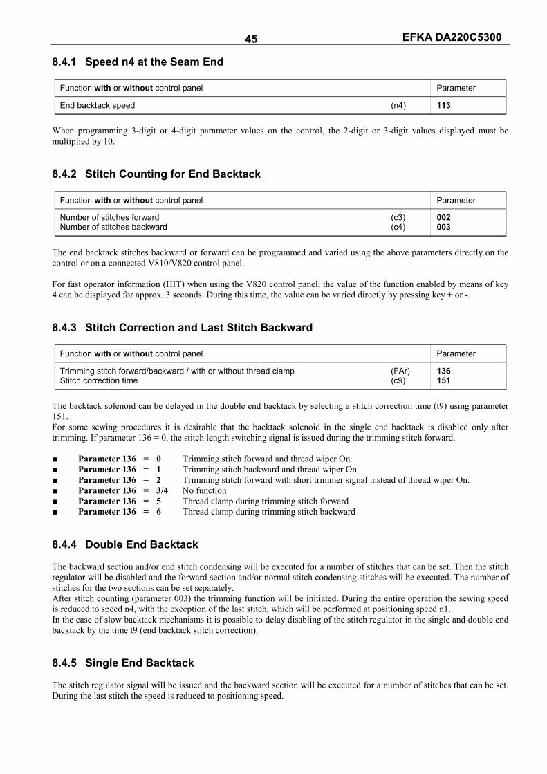
EFKA DA220C5300 45 8.4.1 Speed n4 at the Seam End
Function with or without control panel Parameter
End backtack speed (n4) 113
When programming 3-digit or 4-digit parameter values on the control, the 2-digit or 3-digit values displayed must be multiplied by 10. 8.4.2 Stitch Counting for End Backtack
Function with or without control panel Parameter
Number of stitches forward (c3) 002 Number of stitches backward (c4) 003
The end backtack stitches backward or forward can be programmed and varied using the above parameters directly on the control or on a connected V810/V820 control panel. For fast operator information (HIT) when using the V820 control panel, the value of the function enabled by means of key 4 can be displayed for approx. 3 seconds. During this time, the value can be varied directly by pressing key + or -. 8.4.3 Stitch Correction and Last Stitch Backward
Function with or without control panel Parameter
Trimming stitch forward/backward / with or without thread clamp (FAr) 136 Stitch correction time (c9) 151
The backtack solenoid can be delayed in the double end backtack by selecting a stitch correction time (t9) using parameter 151. For some sewing procedures it is desirable that the backtack solenoid in the single end backtack is disabled only after trimming. If parameter 136 = 0, the stitch length switching signal is issued during the trimming stitch forward. Parameter 136 = 0 Trimming stitch forward and thread wiper On. Parameter 136 = 1 Trimming stitch backward and thread wiper On. Parameter 136 = 2 Trimming stitch forward with short trimmer signal instead of thread wiper On. Parameter 136 = 3/4 No function Parameter 136 = 5 Thread clamp during trimming stitch forward Parameter 136 = 6 Thread clamp during trimming stitch backward 8.4.4 Double End Backtack The backward section and/or end stitch condensing will be executed for a number of stitches that can be set. Then the stitch regulator will be disabled and the forward section and/or normal stitch condensing stitches will be executed. The number of stitches for the two sections can be set separately. After stitch counting (parameter 003) the trimming function will be initiated. During the entire operation the sewing speed is reduced to speed n4, with the exception of the last stitch, which will be performed at positioning speed n1. In the case of slow backtack mechanisms it is possible to delay disabling of the stitch regulator in the single and double end backtack by the time t9 (end backtack stitch correction). 8.4.5 Single End Backtack The stitch regulator signal will be issued and the backward section will be executed for a number of stitches that can be set. During the last stitch the speed is reduced to positioning speed.

EFKA DA220C5300 46 8.4.6 Backtack Synchronization
Function with or without control panel Parameter
Backtack synchronization for start and end backtack On/Off (nSo) 123 Backtack synchronization speed (nrS) 124
If parameter 123 is on, the backtack speed will be switched to backtack synchronization speed one stitch before engaging and disengaging of the backtack solenoid. The backtack speed is released at the next position 2. If the synchronization speed, that can be set using parameter 124, is higher than the backtack speed, the latter is maintained. Backtack synchronization is possible in the start and end backtack. 8.5 Start Ornamental Backtack
Function without control panel Control
Single start ornamental backtack LED 1 On Key S2 Double start ornamental backtack LED 2 On Start ornamental backtack Off both LEDs Off
Function with control panel V810/V820
Single start ornamental backtack lefthand arrow above key On Key 1 Double start ornamental backtack righthand arrow above key On Start ornamental backtack Off both arrows Off
Function with or without control panel Parameter
Number of ornamental backtack stitches forward (SAv) 080 Number of ornamental backtack stitches backward (SAr) 081 Start backtack speed (n3) 112 Function “ornamental backtack” On/Off (SrS) 135 Start delay after switching off the sewing foot lift signal (t3) 202 Ornamental backtack stop time (tSr) 210 Last counted forward section in the start ornamental backtack On/Off (Zrv) 215
Difference from the standard start backtack: The drive stops for stitch regulator switching. The stop time can be set. After the backtack section backward follows a backtack section forward with the same number of stitches as the
backward section according to the setting of parameter 215. The number of ornamental backtack stitches can be set with separate parameters. Machines with autoselect resistor 100Ω emit the signal “switch stitch length” during backtack. When using the V820 control panel, direct access by means of the function key (Key 9) is possible!
Function with control panel Parameter
Ornamental backtack On/Off (-F-) 008 = 2
The letter symbols in parentheses ( ) are visible only if the V820 control panel is connected! 8.6 End Ornamental Backtack
Function without control panel Control
Single end ornamental backtack LED 3 On Key S3 Double end ornamental backtack LED 4 On End ornamental backtack Off both LEDs Off
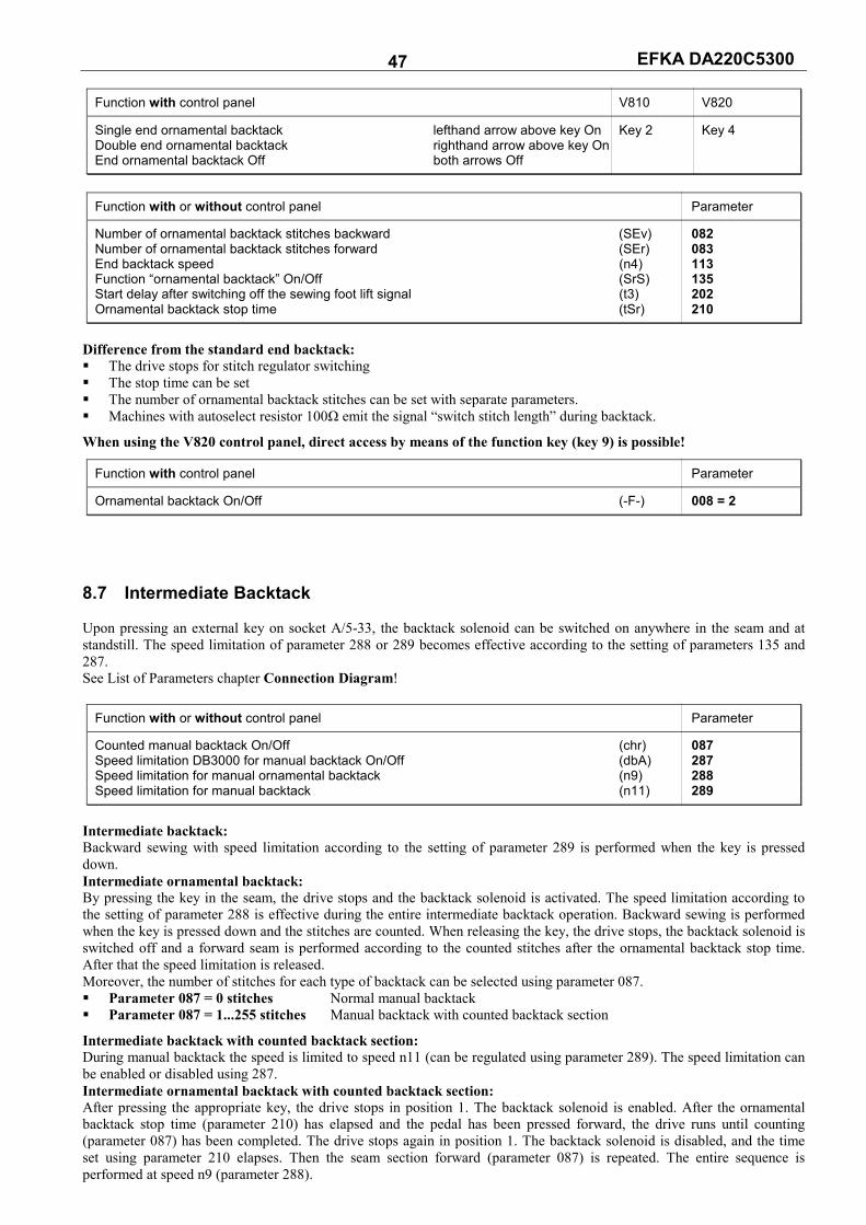
EFKA DA220C5300 47
Function with control panel V810 V820
Single end ornamental backtack lefthand arrow above key On Key 2 Key 4 Double end ornamental backtack righthand arrow above key On End ornamental backtack Off both arrows Off
Function with or without control panel Parameter
Number of ornamental backtack stitches backward (SEv) 082 Number of ornamental backtack stitches forward (SEr) 083 End backtack speed (n4) 113 Function “ornamental backtack” On/Off (SrS) 135 Start delay after switching off the sewing foot lift signal (t3) 202 Ornamental backtack stop time (tSr) 210
Difference from the standard end backtack: The drive stops for stitch regulator switching The stop time can be set The number of ornamental backtack stitches can be set with separate parameters. Machines with autoselect resistor 100Ω emit the signal “switch stitch length” during backtack.
When using the V820 control panel, direct access by means of the function key (key 9) is possible!
Function with control panel Parameter
Ornamental backtack On/Off (-F-) 008 = 2
8.7 Intermediate Backtack Upon pressing an external key on socket A/5-33, the backtack solenoid can be switched on anywhere in the seam and at standstill. The speed limitation of parameter 288 or 289 becomes effective according to the setting of parameters 135 and 287. See List of Parameters chapter Connection Diagram!
Function with or without control panel Parameter
Counted manual backtack On/Off (chr) 087 Speed limitation DB3000 for manual backtack On/Off (dbA) 287 Speed limitation for manual ornamental backtack (n9) 288 Speed limitation for manual backtack (n11) 289
Intermediate backtack: Backward sewing with speed limitation according to the setting of parameter 289 is performed when the key is pressed down. Intermediate ornamental backtack: By pressing the key in the seam, the drive stops and the backtack solenoid is activated. The speed limitation according to the setting of parameter 288 is effective during the entire intermediate backtack operation. Backward sewing is performed when the key is pressed down and the stitches are counted. When releasing the key, the drive stops, the backtack solenoid is switched off and a forward seam is performed according to the counted stitches after the ornamental backtack stop time. After that the speed limitation is released. Moreover, the number of stitches for each type of backtack can be selected using parameter 087. Parameter 087 = 0 stitches Normal manual backtack Parameter 087 = 1...255 stitches Manual backtack with counted backtack section
Intermediate backtack with counted backtack section: During manual backtack the speed is limited to speed n11 (can be regulated using parameter 289). The speed limitation can be enabled or disabled using 287. Intermediate ornamental backtack with counted backtack section: After pressing the appropriate key, the drive stops in position 1. The backtack solenoid is enabled. After the ornamental backtack stop time (parameter 210) has elapsed and the pedal has been pressed forward, the drive runs until counting (parameter 087) has been completed. The drive stops again in position 1. The backtack solenoid is disabled, and the time set using parameter 210 elapses. Then the seam section forward (parameter 087) is repeated. The entire sequence is performed at speed n9 (parameter 288).
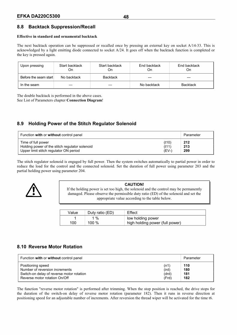
EFKA DA220C5300 48 8.8 Backtack Suppression/Recall Effective in standard and ornamental backtack The next backtack operation can be suppressed or recalled once by pressing an external key on socket A/14-33. This is acknowledged by a light emitting diode connected to socket A/24. It goes off when the backtack function is completed or the key is pressed again.
Upon pressing Start backtack Start backtack End backtack End backtack On On On On
Before the seam start No backtack Backtack --- ---
In the seam --- --- No backtack Backtack
The double backtack is performed in the above cases. See List of Parameters chapter Connection Diagram! 8.9 Holding Power of the Stitch Regulator Solenoid
Function with or without control panel Parameter
Time of full power (t10) 212 Holding power of the stitch regulator solenoid (t11) 213 Upper limit stitch regulator ON period (EV-) 299
The stitch regulator solenoid is engaged by full power. Then the system switches automatically to partial power in order to reduce the load for the control and the connected solenoid. Set the duration of full power using parameter 203 and the partial holding power using parameter 204.
Value Duty ratio (ED) Effect 1 1 % low holding power 100 100 % high holding power (full power)
8.10 Reverse Motor Rotation
Function with or without control panel Parameter
Positioning speed (n1) 110 Number of reversion increments (ird) 180 Switch-on delay of reverse motor rotation (drd) 181 Reverse motor rotation On/Off (Frd) 182
The function "reverse motor rotation" is performed after trimming. When the stop position is reached, the drive stops for the duration of the switch-on delay of reverse motor rotation (parameter 182). Then it runs in reverse direction at positioning speed for an adjustable number of increments. After reversion the thread wiper will be activated for the time t6.
CAUTION!If the holding power is set too high, the solenoid and the control may be permanently damaged. Please observe the permissible duty ratio (ED) of the solenoid and set the
appropriate value according to the table below.
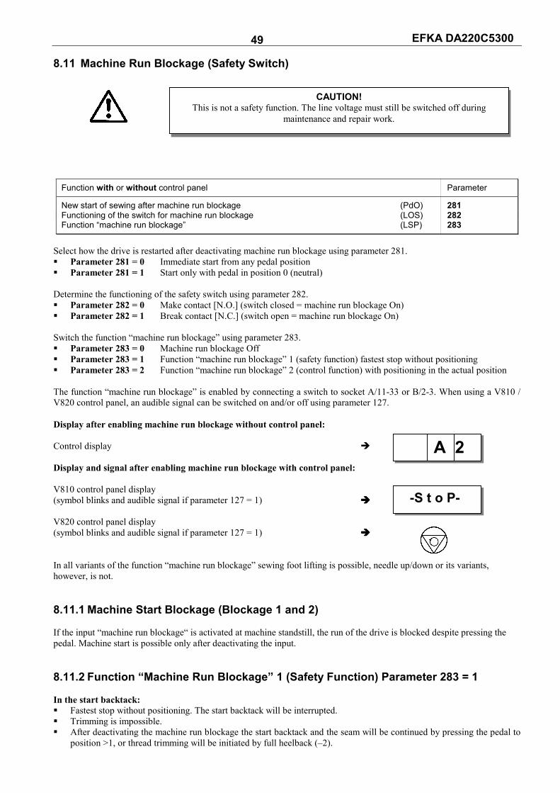
EFKA DA220C5300 49 8.11 Machine Run Blockage (Safety Switch)
Function with or without control panel Parameter
New start of sewing after machine run blockage (PdO) 281 Functioning of the switch for machine run blockage (LOS) 282 Function “machine run blockage” (LSP) 283
Select how the drive is restarted after deactivating machine run blockage using parameter 281. Parameter 281 = 0 Immediate start from any pedal position Parameter 281 = 1 Start only with pedal in position 0 (neutral) Determine the functioning of the safety switch using parameter 282. Parameter 282 = 0 Make contact [N.O.] (switch closed = machine run blockage On) Parameter 282 = 1 Break contact [N.C.] (switch open = machine run blockage On) Switch the function “machine run blockage” using parameter 283. Parameter 283 = 0 Machine run blockage Off Parameter 283 = 1 Function “machine run blockage” 1 (safety function) fastest stop without positioning Parameter 283 = 2 Function “machine run blockage” 2 (control function) with positioning in the actual position The function “machine run blockage” is enabled by connecting a switch to socket A/11-33 or B/2-3. When using a V810 / V820 control panel, an audible signal can be switched on and/or off using parameter 127. Display after enabling machine run blockage without control panel: Control display Display and signal after enabling machine run blockage with control panel: V810 control panel display (symbol blinks and audible signal if parameter 127 = 1) V820 control panel display (symbol blinks and audible signal if parameter 127 = 1) In all variants of the function “machine run blockage” sewing foot lifting is possible, needle up/down or its variants, however, is not. 8.11.1 Machine Start Blockage (Blockage 1 and 2) If the input “machine run blockage“ is activated at machine standstill, the run of the drive is blocked despite pressing the pedal. Machine start is possible only after deactivating the input. 8.11.2 Function “Machine Run Blockage” 1 (Safety Function) Parameter 283 = 1 In the start backtack: Fastest stop without positioning. The start backtack will be interrupted. Trimming is impossible. After deactivating the machine run blockage the start backtack and the seam will be continued by pressing the pedal to
position >1, or thread trimming will be initiated by full heelback (–2).
CAUTION!This is not a safety function. The line voltage must still be switched off during
maintenance and repair work.
A 2
-S t o P-
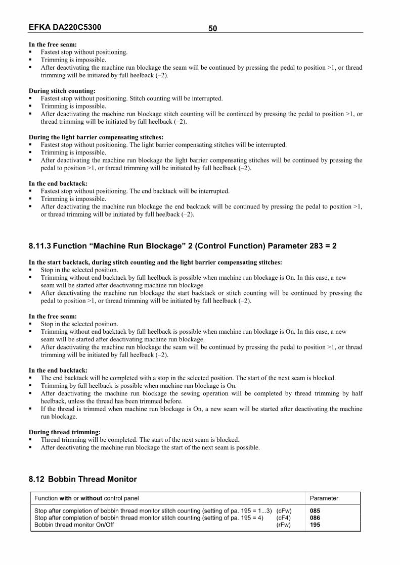
EFKA DA220C5300 50 In the free seam: Fastest stop without positioning. Trimming is impossible. After deactivating the machine run blockage the seam will be continued by pressing the pedal to position >1, or thread
trimming will be initiated by full heelback (–2). During stitch counting: Fastest stop without positioning. Stitch counting will be interrupted. Trimming is impossible. After deactivating the machine run blockage stitch counting will be continued by pressing the pedal to position >1, or
thread trimming will be initiated by full heelback (–2). During the light barrier compensating stitches: Fastest stop without positioning. The light barrier compensating stitches will be interrupted. Trimming is impossible. After deactivating the machine run blockage the light barrier compensating stitches will be continued by pressing the
pedal to position >1, or thread trimming will be initiated by full heelback (–2). In the end backtack: Fastest stop without positioning. The end backtack will be interrupted. Trimming is impossible. After deactivating the machine run blockage the end backtack will be continued by pressing the pedal to position >1,
or thread trimming will be initiated by full heelback (–2). 8.11.3 Function “Machine Run Blockage” 2 (Control Function) Parameter 283 = 2 In the start backtack, during stitch counting and the light barrier compensating stitches: Stop in the selected position. Trimming without end backtack by full heelback is possible when machine run blockage is On. In this case, a new
seam will be started after deactivating machine run blockage. After deactivating the machine run blockage the start backtack or stitch counting will be continued by pressing the
pedal to position >1, or thread trimming will be initiated by full heelback (–2). In the free seam: Stop in the selected position. Trimming without end backtack by full heelback is possible when machine run blockage is On. In this case, a new
seam will be started after deactivating machine run blockage. After deactivating the machine run blockage the seam will be continued by pressing the pedal to position >1, or thread
trimming will be initiated by full heelback (–2). In the end backtack: The end backtack will be completed with a stop in the selected position. The start of the next seam is blocked. Trimming by full heelback is possible when machine run blockage is On. After deactivating the machine run blockage the sewing operation will be completed by thread trimming by half
heelback, unless the thread has been trimmed before. If the thread is trimmed when machine run blockage is On, a new seam will be started after deactivating the machine
run blockage. During thread trimming: Thread trimming will be completed. The start of the next seam is blocked. After deactivating the machine run blockage the start of the next seam is possible. 8.12 Bobbin Thread Monitor
Function with or without control panel Parameter
Stop after completion of bobbin thread monitor stitch counting (setting of pa. 195 = 1...3) (cFw) 085 Stop after completion of bobbin thread monitor stitch counting (setting of pa. 195 = 4) (cF4) 086 Bobbin thread monitor On/Off (rFw) 195

EFKA DA220C5300 51 If the bobbin thread monitor function is On (parameter 195 = 1...4), the type of control and the set maximum speed are displayed for 1 sec. After power On. Display of maximum speed: Type of control (e. g. 4000 RPM)
Then the bobbin thread monitor status display appears. Number of bobbin thread monitor stitches: Status display (e. g. 250 stitches) At this point (after power On) the number of stitches can be regulated in steps of 10 with the +/- key. The function DED = Direct Input of Speed Limitation is available only after having started sewing or trimming. 8.12.1 Input Signals The form of input signal helps distinguish which of the bobbins is empty. Righthand bobbin empty: = Continuous signal (min. 1 sec.) Lefthand bobbin empty: = Frequency 5 Hz or signal for approx. 100 msec Lefthand and righthand bobbin empty: = Frequency 10 Hz or signal for approx. 50 msec 8.12.2 Parameter 195 = 0 – No Bobbin Thread Monitor Function The bobbin thread monitor function is Off. 8.12.3 Parameter 195 = 1 – Model 270 / No Stop / Sewing Foot Down after Seam End After the bobbin is empty, the bobbin thread counter is activated when receiving an input signal, and the bobbin thread monitor symbol blinks on the display of the V810 or V820 control panel. After counting, C is displayed for the lefthand bobbin and D for the righthand bobbin on the V810 control panel. On the V820 control panel, another symbol for the righthand, lefthand bobbin or both bobbins is displayed instead of the type designation. This symbol is also displayed on the control unit. Furthermore, the respective LEDs blink with approx. 4 Hz on the machine (righthand, lefthand or both). The displays remain on even if the input signal is no longer received. The sewing foot is not lifted after thread trimming and after counting. The sewing foot is lifted only after the pedal has been heeled back from position 0 (neutral). The displays go off (the blinking frequency of 4 Hz is switched off), if no more input signals are received after thread trimming and the subsequent start of sewing after 14 stitches. This is an indicator that the bobbin has been replaced, and the bobbin thread counter is reset to zero. 8.12.4 Parameter 195 = 2 – Model 767, N291 / With Stop / Sewing Foot Up after Seam
End After the bobbin is empty, the bobbin thread counter is activated when receiving an input signal, and the bobbin thread monitor symbol blinks on the display of the V810 or V820 control panel. After counting, C is displayed for the lefthand bobbin and D for the righthand bobbin on the V810 control panel. On the V820 control panel, another symbol for the righthand, lefthand bobbin or both bobbins is displayed instead of the type designation. This symbol is also displayed on the control unit. Furthermore, the respective LEDs blink with approx. 4 Hz on the machine (righthand, lefthand or both), and the drive stops. Even automatic seam sections like seams with stitch counting or light barrier seams are interrupted. They can be completed by pressing the pedal forward from position 0 (neutral). Note the following exceptions: If bobbin thread counting is completed in the start backtack, the latter will be completed and the drive stops. If bobbin thread counting is completed in the end backtack, the latter will be fully completed with the thread trimming
operation. After thread trimming the sewing foot is automatically lifted. The displays go off (the blinking frequency of 4 Hz is switched off), if no more input signals are received after thread trimming and the subsequent start of sewing after 14 stitches. This is an indicator that the bobbin has been replaced, and the bobbin thread counter is reset to zero.
4000 dA220c
250 --II--

EFKA DA220C5300 52 8.12.5 Parameter 195 = 3 – Model 767, N291 / With Stop / Sewing Foot Down after Seam
End After the bobbin is empty, the bobbin thread counter is activated when receiving an input signal, and the bobbin thread monitor symbol blinks on the display of the V810 or V820 control panel. After counting, C is displayed for the lefthand bobbin and D for the righthand bobbin on the V810 control panel. On the V820 control panel, another symbol for the righthand, lefthand bobbin or both bobbins is displayed instead of the type designation. This symbol is also displayed on the control unit. Furthermore, the respective LEDs blink with approx. 4 Hz on the machine (righthand, lefthand or both), and the drive stops. The sewing foot is not lifted after thread trimming. The sewing foot is lifted only after the pedal has been heeled back from position 0 (neutral). The displays go off (the blinking frequency of 4 Hz is switched off), if no more input signals are received after thread trimming and the subsequent start of sewing after 14 stitches. This is an indicator that the bobbin has been replaced, and the bobbin thread counter is reset to zero. 8.12.6 Parameter 195 = 4 – With Bobbin Thread Monitor Stitch Counting By pressing a key connected to socket A/12-33, a stitch counter is activated (max. 25500 stitches, can be set using parameter 086), and the bobbin thread monitor symbols are continuously displayed. When a V820 control panel is connected, the function can be activated using key 8. At each intermediate stop, the remaining number of stitches will be displayed. When counting is completed, the bobbin thread monitor symbol (righthand or lefthand) blinks on the display of the V820 control panel. C is displayed for the lefthand bobbin and D for the righthand bobbin on the V810 control panel. Furthermore, the respective LEDs blink with approx. 4 Hz on the machine, and the drive stops. Even automatic seam sections, except start and end backtack, are interrupted. The seam can be continued by pressing the pedal forward from position 0 (neutral). The number of stitches is set such that after completing these stitches, the bobbin is not completely empty. After replacing the bobbin, the key must be pressed so that the counter is reset to the preset value and activated again. If the drive is switched off during bobbin thread monitor counting, this value is saved and counting is continued after power On. If the key is pressed for less than one second, the counter is set to the preset value. Key pressed >1 sec. Bobbin thread monitor function is deactivated Key pressed <1 sec. Counter is set to the preset value 8.13 Needle Cooling / Under-Edge Trimmer
Function with or without control panel Parameter
Switch speed for needle cooling On/Off (nnk) 120 Switch-off delay of needle cooling after stop (dnk) 183 Needle cooling/under-edge trimmer function (Fnk) 185
Parameter 185 = 1 Needle cooling: Needle cooling is switched on during the entire sewing operation. Switching off
after the stop can be delayed by the time “switch-off delay of needle cooling after stop”, which can be set with parameter 183.
Parameter 185 = 2 Under-edge trimmer: The output will be activated by pressing the pedal forward. Parameter 185 = 3 Needle cooling depending on speed: The corresponding switch speed can be set using parameter
120.
When using the V820 control panel, direct access by means of the function key (key 9) is possible!
Function with control panel Parameter
Needle cooling On/Off (-F-) 008 = 4
8.14 Function Modules for Output A Depending on the mode selected with parameter 250 several sequences can be initiated by pressing the A key (socket A/8). Affected are, inter alia, the functions “output A” (socket A/30), “indicator LED A” (socket A/29), “sewing process”, “backtacking” and “speed limitation”.

EFKA DA220C5300 53 8.14.1 Function Modules for Output A / No Function (Parameter 250 = 0) Function module for output A is switched off. 8.14.2 Function Module for Output A / Switch Stitch Length (Pa. 250 = 1)
Function with or without control panel Parameter
Switch stitch length with output A (FmA) 250 = 1 Light barrier compensating stitches for long stitch length (LS) 004 Light barrier compensating stitches for normal stitch length (cLS) 010 Output A remains active or becomes inactive after the seam end (AFA) 251 Output A inverted/not inverted (Ain) 252 Speed limitation DB3000 (n11) 289
If output A is activated, the normal stitch length is effective. LED A is off. Output A can be inverted with parameter 252. After power On, the normal stitch length will be switched on, i.e. output A = On and LED A = Off. By pressing the A key, output A is switched off and LED A is switched on. The maximum speed is limited to DB3000
(parameter 289). Start and end backtack will be suppressed. When the key is pressed again, the status after power On is reset. If parameter 251 = 1, the status after power On will be activated after thread trimming. When completing the seam by light barrier, different parameters (004, 010) apply to the two light barrier stitch counts.
Output A LED A Speed limitation Backtack Remark
Power On On Off normal stitch length A key Off On DB3000 suppressed long stitch length A key again On Off normal stitch length Thread trimming, On Off normal stitch length if 251=1
8.14.3 Function Module for Output A / Fullness Control with Speed Limitation
(Pa. 250 = 2)
Function with or without control panel Parameter
Fullness control with speed limitation at output A (FmA) 250 = 2 Number of end ornamental backtack stitches backward (SEr) 082 Number of end ornamental backtack stitches forward (SEv) 083 Output A remains active or becomes inactive after the seam end (AFA) 251 Speed limitation DB3000 (n11) 289
After power On, output A and LED A are switched off. Output A and LED A can be switched on any time by pressing the A key. The speed is limited to DB3000 (parameter
289). Output A, LED A and the speed limitation are switched off by pressing the key again. If an intermediate backtack is switched on and output A is activated, the latter is deactivated first and the backtack
solenoid output is switched on after a certain time (parameter 210). LED A remains On during this process. When the intermediate backtack is switched off, output A is switched on immediately. During start backtack, output A is off and LED A remains on. If output A is on, the end backtack will be performed as follows. When activating the end backtack function, the drive
stops. Output A is switched off and the backtack solenoid is switched on. After the time set with parameter 210 has elapsed, the drive restarts and performs the end backtack.
After thread trimming, the setting of parameter 251 determines whether output A and LED A are switched on or off at the beginning of the next seam.
If parameter 251 = 1, the status after power On will be activated after thread trimming.

EFKA DA220C5300 54
Output A LED A Speed limitation Backtack Remark
Power On Off Off Fullness Off A key On On DB3000 Fullness On In the start backtack Off On Speed n3 Fullness Off In the end backtack Off On Speed n4 End backtack Fullness Off After thread On On DB3000 Fullness On trimming + 251=0 After thread Off Off Fullness Off trimming + 251=1
8.14.4 Function Module for Output A / Fullness Control without Speed Limitation
(Pa. 250 = 3)
Function with or without control panel Parameter
Fullness control without speed limitation at output A (FmA) 250 = 3 Number of end ornamental backtack stitches backward (SEr) 082 Number of end ornamental backtack stitches forward (SEv) 083 Output A remains active or becomes inactive after the seam end (AFA) 251
After power On, output A and LED A are switched on. Output A and LED A can be switched off any time by pressing the A key. Output A and LED A are switched on by pressing the key again. If an intermediate backtack is switched on and output A is activated, the latter is deactivated first and the backtack
solenoid output is switched on after a certain time (parameter 210). LED A remains On during this process. When the intermediate backtack is switched off, output A is switched on immediately. During start backtack, output A is off and LED A remains on. If output A is on, the end backtack will be performed as follows. When activating the end backtack function, the drive
stops. Output A is switched off and the backtack solenoid is switched on. After the time set with parameter 210 has elapsed, the drive restarts and performs the end backtack.
After thread trimming, the setting of parameter 251 determines whether output A and LED A are switched on or off at the beginning of the next seam.
If parameter 251 = 1, the status after power On will be activated after thread trimming.
Output A LED A Speed limitation Backtack Remark
Power On On On Fullness On A key Off Off Fullness Off A key again On On Fullness On In the start backtack Off On Speed n3 Fullness Off In the end backtack Off On Speed n4 End backtack Fullness Off After thread On On Fullness On trimming + 251=1
8.14.5 Function Module for Output A / Single Stitch with Short Stitch Length
(Pa. 250 = 4)
Function with or without control panel Parameter
Single stitch with reduced stitch length (FmA) 250 = 4
Output A will be switched on by pressing a key after the start of sewing, at intermediate stop and with the sewing foot
down. One full rotation will be performed on condition that the drive had been positioned in position 1. If the key remains pressed down and the pedal is pressed forward after a single stitch, output A and LED A remain On.
Sewing is performed with short stitch length until the key is pressed again, or output A and LED A are switched off by the end backtack or the thread trimmer.
If the A key is pressed during sewing, or sewing is started when pressing the key, output A and LED A will be switched on.
Output A and LED A will be switched off by pressing the key again or by the end backtack or the thread trimmer. A manual backtack is impossible when output a is switched on. Pressing a key during automatic seams by stitch counting or light barrier has no effect.

EFKA DA220C5300 55
Output A LED A Remark
Power On Off Off A key after start of sewing On for one rotation On Sewing foot down Press A key during sewing, or On, sewing with short stitch On Manual backtack impossible press A key first and then start length End backtack without thread Off Off trimming
8.14.6 Function Module for Output A / Lift/Lower Roller (Pa. 250 = 5)
Function with or without control panel Parameter
Lift/lower roller (output A) (FmA) 250 = 5 Number of stitches until lowering the roller (cA) 253 Time interval which can be varies by the number of stitches set with parameter 253 On/Off(PLc) 260 Roller lifting depending on sewing foot lift and backtack (FLk) 261 When enabling high lift for walking foot, roller remains lowered/lifted (hPt) 262
After power On, output A and LED A are switched on. By pressing a key after power On before starting the seam output A and LED A are switched off. By pressing the key again after power On before starting the seam the roller function and LED A is switched on.
Output A remains on (roller up). After the seam start (roller function on) the roller will be lowered after a number of stitches that can be set (parameter
253) after the start backtack has been completed (if start backtack off, at the seam start). The function of the set stitches can be enabled and disabled using parameter 260. Counting can be interrupted by pressing a key. The roller is immediately lowered.
If the sewing foot is lifted and the roller is down, the roller is also lifted. After the sewing foot has been lowered, the roller is also lowered after the number of stitches set with parameter 253. Counting can be interrupted by pressing a key. The roller is immediately lowered. If the number of stitches is set to 0, the roller is immediately lowered together with the sewing foot.
Whenever a manual backtack is performed with the roller down, the roller is immediately lifted. After the backtack the roller is immediately lowered.
When the key is pressed for the first time during the sewing operation, the roller function is disabled. The roller is lifted and LED A goes off. This status remains until the key is pressed again (even after thread trimming). By pressing the key once more the roller function is enabled again. The roller is lowered and LED A switched on.
The roller is lifted when starting the end backtack or the thread trimmer.
Output A LED A Roller Sewing foot lift
Power On On On up A key Off Off down Press A key once more On On up In the start backtack On On up down After the start backtack during counting *) On On up down A key, after the start backtack during counting *) Off Off down down After the start backtack after counting *) Off Off down down Manual backtack On On up down Sewing foot up On On up up After actuating the sewing foot during counting *) On On up down A key after actuating the sewing foot during counting *) Off Off down down A key in the seam On On up A key once more in the seam Off Off down In the end backtack and during thread trimming On On up down After thread trimming if roller On On On up After thread trimming if roller Off On On up
*) Number of stitches until output A is enabled (parameter 253).

EFKA DA220C5300 56 The following functions can be set with parameter 261: Parameter 261 = 0 The roller is lifted without sewing foot lift and backtack. Parameter 261 = 1 The roller is lifted with sewing foot lift and backtack. Parameter 261 = 2 The roller is lifted with sewing foot lift. After the sewing foot has been lowered, the roller will be
lowered after the number of stitches set with parameter 253 and their enabling using parameter 260, or pressing a key.
Parameter 261 = 3 The roller is lifted with the backtack. After the backtack the roller will be immediately lowered. If the roller is lifted when activating the intermediate backtack, it remains lifted until after completing the backtack.
The following function can be set with parameter 262 if parameter 250 is et at “11“ and 255 at “5“ or parameter 250 at “5“ and 255 at “11“. Parameter 262 = 0 The roller remains lowered when enabling high lift for walking foot. Parameter 262 = 1 The roller is lifted when enabling high lift for walking foot. 8.14.7 Function Module for Output A / Lift/Lower Fabric Stop (Pa. 250 = 6)
Function with or without control panel Parameter
Lift/lower fabric stop (output A) (FmA) 250 = 6 Output A inverted / not inverted (Ain) 252
The fabric stop is lifted by enabling output A. It is effective if output A is off. LED A lights up when the fabric stop is
down or output A is off. After power On, output A is On and LED A is Off. Output A can be inverted with parameter 252. By pressing a key, output A is switched off and LED A is switched on. The fabric stop is effective. This status is
maintained until after thread trimming and can be cancelled only by pressing the key again or by power Off/On. If the sewing foot is lifted, the fabric stop is as well lifted. Output A is switched on and LED A remains on. If the sewing foot is lowered, the fabric stop is as well lowered. Output A is switched off and LED A remains on. By pressing the key again, the fabric stop is disabled. Output A is switched on and LED A is switched off. This status
is maintained until after thread trimming and can be cancelled only by pressing the key again.
Output A LED A Fabric stop Sewing foot lift
Power On On Off up Press A key; sewing foot up On On up up Press A key once more; sewing foot up On Off up up Press A key once more; sewing foot down Off On down down Sewing foot up On On up up After thread trimming and sewing foot up On On up up After thread trimming and sewing foot down Off On down down
8.14.8 Function Module for Output A / Second Thread Tension (Pa. 250 = 7)
Function with or without control panel Parameter
Second thread tension (output A) (FmA) 250 = 7 Output A remains active or becomes inactive after the seam end (AFA) 251 Output A inverted / not inverted (Ain) 252
The second thread tension can be enabled or disabled as desired, not however, during automatic seam sections. After power On, output A and LED A are switched off. Output A can be inverted with parameter 252. By pressing the key for the first time, output A and LED A are switched on. By pressing the key for the second time, output A and LED A are switched off again. If parameter 251 = 1, the status after power On will be activated after thread trimming.
Functional sequence if Parameter 252 = 0 Parameter 252 = 1
Output A LED A Output A LED A
Power On Off Off On Off Press A key On On Off On Press A key again or thread trimming if parameter 251 = 1 Off Off On Off

EFKA DA220C5300 57 8.14.9 Function Module for Output A / Manual Edge Trimmer (Pa. 250 = 8)
Function with or without control panel Parameter
Manual edge trimmer (output A) (FmA) 250 = 8 Output A remains active or becomes inactive after the seam end (AFA) 251 Edge trimmer influences sewing foot lifting On/Off (kFk) 267
The edge trimmer is enabled by activating output A. If parameter 251 = 1, the edge trimmer will be disabled after thread trimming. After power On, the edge trimmer and LED A are switched off. The edge trimmer can be enabled any time by pressing the A key (output A and LED A On). The edge trimmer is disabled by pressing the key again (output A and LED A Off). If parameter 251 = 1, the edge trimmer will be activated after thread trimming as after power On.
Output A LED A Remark
Power On Off Off Edge trimmer Off Press A key On On Edge trimmer On Press A key again Off Off Edge trimmer Off After thread trimming if pa. 251 = 1 Off Off Edge trimmer Off
8.14.10 Function Module for Output A / Automatic Edge Trimmer (Pa. 250 = 9)
Function with or without control panel Parameter
Automatic edge trimmer (output A) (FmA) 250 = 9 Edge trimmer remains active at the seam end as before thread trimming, or (AFA) 251 it will be activated as after power On Number of stitches until enabling the edge trimmer (cA) 253 Number of stitches until disabling the edge trimmer (cA_) 254 Edge trimmer influences sewing foot lifting On/Off (kFk) 267
The edge trimmer is enabled by activating output A (M6 on socket A/30). This is indicated by LED A (M10 on socket A/29). The starting torque of the edge trimmer is determined using parameter 253 (number of stitches). The edge trimmer ON period is set using parameter 254 (number of stitches). The following operational statuses are possible: Automatic operation: Parameter 253 >0, Parameter 254 >0, Parameter 251 = 0 or Parameter 251 = 1 Semiautomatic operation: Parameter 253 >0, Parameter 254 = 0, Parameter 251 = 0 or Parameter 251 = 1 Parameter 253 = 0, Parameter 254 >0, Parameter 251 = 0 or Parameter 251 = 1 Manual operation: Parameter 253 = 0, Parameter 254 = 0, Parameter 251 = 0 or Parameter 251 = 1 Parameter 251 = 0 The edge trimmer switching state is maintained as before thread trimming. Parameter 251 = 1 The edge trimmer switching state is set as after power On. Parameter 267 = 0 The edge trimmer remains On, independently of sewing foot lifting. Parameter 267 = 1 The edge trimmer is disabled when the sewing foot is lifted. Automatic Operation:
Parameter 253 > 0, 254 > 0, 251 = 0 Output A LED A Remark
Power On Off Off Press A key before the seam start On On Press A key again before the seam start Off Off After the seam start, counting pa. 253 Off Blinking Counting can be interrupted with the A key End counting pa. 253 On On Start counting pa. 254 On On Counting can be interrupted with the A key End counting pa. 254 Off Off Press A key On On Manual enabling Press A key Off Off Manual disabling After thread trimming Off Off

EFKA DA220C5300 58 Semiautomatic Operation:
Parameter 253 > 0, 254 = 0, 251 = 0 Output A LED A Remark
Power On Off Off Press A key before the seam start On On Press A key again before the seam start Off Off After the seam start, counting pa. 253 Off Blinking Counting can be interrupted with the A key End counting pa. 253 On On Start counting pa. 254 = 0 On On Edge trimmer disabled only manually Press A key Off Off Manual disabling After thread trimming Off Off
Parameter 253 > 0, 254 = 0, 251 = 1 Output A LED A Remark
Power On Off Off Press A key before the seam start On On Press A key again before the seam start Off Off After the seam start, counting pa. 253 Off Blinking Counting can be interrupted with the A key End counting pa. 253 On On Start counting pa. 254 = 0 On On Edge trimmer disabled only manually After thread trimming Off Off Status as after power On
Parameter 253 = 0, 254 > 0, 251 = 0 Output A LED A Remark
Power On Off Off Press A key before the seam start On On Press A key again before the seam start Off Off After the seam start, counting pa. 253 = 0 Off Off Press A key On On Trigger key On (special case) Start counting pa. 254 On On End counting pa. 254 Off Off Press A key On On Manual enabling Press A key Off Off Manual disabling After thread trimming Off Off
Parameter 253 = 0, 254 > 0, 251 = 1 Output A LED A Remark
Power On Off Off Press A key before the seam start On On Press A key again before the seam start Off Off After the seam start, counting pa. 253 = 0 Off Off Press A key On On Trigger key On (special case) Start counting pa. 254 On On End counting pa. 254 Off Off Press A key On On Manual enabling After thread trimming Off Off
Manual Operation:
Parameter 253 = 0, 254 = 0, 251 = 0 Output A LED A Remark
Power On Off Off Press A key before the seam start or in the On On seam Press A key before the seam start or in the Off Off seam Press A key before the seam start or in the On On seam After thread trimming On On

EFKA DA220C5300 59
Parameter 253 = 0, 254 = 0, 251 = 1 Output A LED A Remark
Power On Off Off Press A key before the seam start or in the On On seam Press A key before the seam start or in the Off Off seam Press A key before the seam start or in the On On seam After thread trimming Off Off
8.14.11 Function Module for Output A / Triflex Function (Pa. 250 = 10)
Function with or without control panel Parameter
Triflex function (FmA) 250 = 10 Speed limitation DB2000 (n10) 117 Output A remains active or becomes inactive after the seam end (AFA) 251 Output A inverted / not inverted (Ain) 252 Function second thread tension with output B (Fmb) 255 = 7
The “Triflex” function affects stitch length, thread tension, speed limitation and backtacking. First a "normal" seam with short stitch length, without speed limitation, with normal thread tension and backtacking will be performed. A “basted seam” will be performed by pressing the key, i.e. long stitch length, low thread tension (output B), speed limitation and backtacking. The seam is reset to “normal” by pressing the key for the second time or by thread trimming (if parameter 251 = 1). While using this “Triflex” function, output B must be set to mode 7 (parameter 255 = 7). After power On, output A is On and LED A is Off. By pressing the A key, output A is switched off and LED A is switched on.. The speed is limited to DB2000
(parameter 117); start and end backtack are off. Manual backtack is impossible. The status after power On will be reset by pressing the key again. If parameter 251 = 1, the status after power On will be activated after thread trimming. The signal at output A can be inverted with parameter 252.
Output A LED A Speed limitation Remark
Power On On Off Output A can be inverted with parameter 252 Press A key Off On DB2000 Manual backtack impossible, start and end backtack are suppressed Press A key again or initiate On Off thread trimming if parameter 251 = 0
8.14.12 Function Module for Output A / High Lift for Walking Sewing Foot
(Pa. 250 = 10)
Function with or without control panel Parameter
High lift for walking foot with output A (FmA) 250 = 11 High lift walking speed (n10) 117 High lift for walking foot operational mode stored = 1 / not stored = 0 (hPr) 138 Run-out time of high lift walking speed after disabling high lift for walking foot (thP) 152 Number of stitches until disabling of output A (cA_) 254 When enabling high lift for walking foot, the roller remains lowered/lifted (hPt) 262
By pressing the A key, output A and LED A are switched on and set to maximum high lift. The solenoid valve can be switched on any time. The maximum speed is limited to high lift walking speed (DB2000). If the actual speed is higher than high lift walking speed, the drive slows down to high lift walking speed, before output A is enabled. Output A and LED A are immediately switched off by disabling the maximum high lift. The speed limitation will, however, be released only after a time lag that can be set (parameter 152).
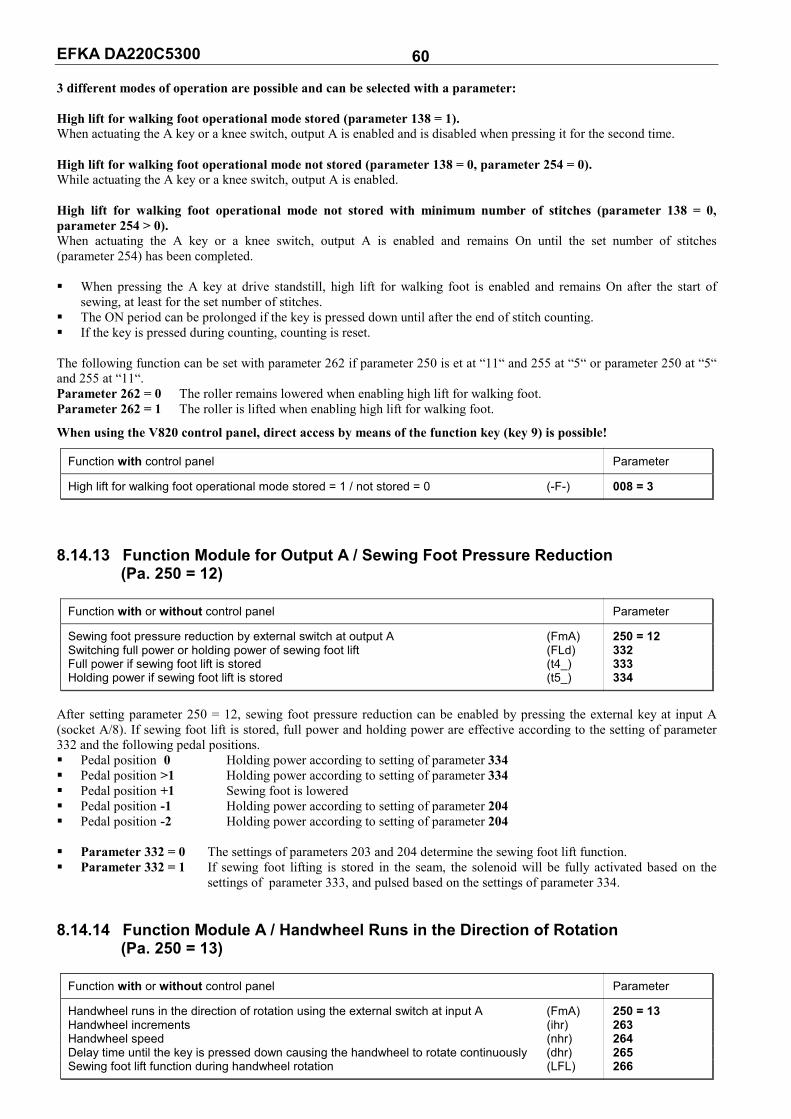
EFKA DA220C5300 60 3 different modes of operation are possible and can be selected with a parameter: High lift for walking foot operational mode stored (parameter 138 = 1). When actuating the A key or a knee switch, output A is enabled and is disabled when pressing it for the second time. High lift for walking foot operational mode not stored (parameter 138 = 0, parameter 254 = 0). While actuating the A key or a knee switch, output A is enabled. High lift for walking foot operational mode not stored with minimum number of stitches (parameter 138 = 0, parameter 254 > 0). When actuating the A key or a knee switch, output A is enabled and remains On until the set number of stitches (parameter 254) has been completed. When pressing the A key at drive standstill, high lift for walking foot is enabled and remains On after the start of
sewing, at least for the set number of stitches. The ON period can be prolonged if the key is pressed down until after the end of stitch counting. If the key is pressed during counting, counting is reset. The following function can be set with parameter 262 if parameter 250 is et at “11“ and 255 at “5“ or parameter 250 at “5“ and 255 at “11“. Parameter 262 = 0 The roller remains lowered when enabling high lift for walking foot. Parameter 262 = 1 The roller is lifted when enabling high lift for walking foot.
When using the V820 control panel, direct access by means of the function key (key 9) is possible!
Function with control panel Parameter
High lift for walking foot operational mode stored = 1 / not stored = 0 (-F-) 008 = 3
8.14.13 Function Module for Output A / Sewing Foot Pressure Reduction
(Pa. 250 = 12)
Function with or without control panel Parameter
Sewing foot pressure reduction by external switch at output A (FmA) 250 = 12 Switching full power or holding power of sewing foot lift (FLd) 332 Full power if sewing foot lift is stored (t4_) 333 Holding power if sewing foot lift is stored (t5_) 334
After setting parameter 250 = 12, sewing foot pressure reduction can be enabled by pressing the external key at input A (socket A/8). If sewing foot lift is stored, full power and holding power are effective according to the setting of parameter 332 and the following pedal positions. Pedal position 0 Holding power according to setting of parameter 334 Pedal position >1 Holding power according to setting of parameter 334 Pedal position +1 Sewing foot is lowered Pedal position -1 Holding power according to setting of parameter 204 Pedal position -2 Holding power according to setting of parameter 204 Parameter 332 = 0 The settings of parameters 203 and 204 determine the sewing foot lift function. Parameter 332 = 1 If sewing foot lifting is stored in the seam, the solenoid will be fully activated based on the
settings of parameter 333, and pulsed based on the settings of parameter 334. 8.14.14 Function Module A / Handwheel Runs in the Direction of Rotation
(Pa. 250 = 13)
Function with or without control panel Parameter
Handwheel runs in the direction of rotation using the external switch at input A (FmA) 250 = 13 Handwheel increments (ihr) 263 Handwheel speed (nhr) 264 Delay time until the key is pressed down causing the handwheel to rotate continuously (dhr) 265 Sewing foot lift function during handwheel rotation (LFL) 266

EFKA DA220C5300 61 After setting parameter 250 = 13, the handwheel can be made to rotate according to the setting of parameter 161 by pressing the external key at input A (socket A/8). The number of increments for handwheel rotation after briefly pressing the key can be selected using parameter 263. The speed of handwheel rotation can be selected using parameter 264. A delay time is set using parameter 265. If the key is pressed briefly, i.e. for less than the set time, the increments set using parameter 263 are carried out. If the key is kept pressed down for more than the set delay time, the handwheel rotates continuously. The sewing foot can be set as follows using parameter 266. Parameter 266 = 0 When pressing the key, the sewing foot lowers during handwheel rotation. Parameter 266 = 1 The sewing foot remains lifted during handwheel rotation, if the pedal is pressed to pos. –1 or
automatic sewing foot lifting has been set. When using a control panel, the functions can be assigned to the F1 and F2 keys using parameters 293 and 294. Parameter 293/294 = 8 Press key F1/F2 for the handwheel to run in the direction of rotation Parameter 293/294 = 9 Press key F1/F2 for the handwheel to run in the opposite direction of rotation 8.14.15 Function Module A / Handwheel Runs in the Opposite Direction of Rotation
(Pa. 250 = 13)
Function with or without control panel Parameter
Handwheel runs in the opposite direction of rotation by external switch at input A (FmA) 250 = 14
After setting parameter 250 = 14, the handwheel runs in the opposite direction of rotation. All other parameters fulfill the same functions as with setting “13“. 8.15 Function Modules for Output B The functions for the modules of outputs A and B are identical. Therefore, use description of function module A, with
the exception of the parameters. Parameters 255...259 are assigned for functions modules B. In case the settings of function modules A and B are identical, function module A has priority. The functions of
function module B would be disabled in that case.
Function with or without control panel Parameter
Function modules for output B (socket A/32) (Fmb) 255 Output B remains active or becomes inactive after the seam end (bFA) 256 Output B inverted / not inverted (bin) 257 Number of stitches until enabling of output B (cb) 258 Number of stitches until disabling of output B (cb_) 259 Time interval which can be varied by the number of stitches set with parameter 258 On/Off (PLc) 260 Roller lifting depending on sewing foot lift and backtack (FLk) 261 When enabling high lift for walking foot, the roller remains lowered/lifted (hPt) 262 Handwheel increments (ihr) 263 Handwheel speed (nhr) 264 Delay time until the key is pressed down causing the handwheel to rotate continuously (dhr) 265 Sewing foot lift function during handwheel rotation (LFL) 266
Depending on the mode selected with parameter 255 several sequences can be initiated by pressing the B key (in1 on socket A/7). Functions “output B” (M5 on socket A/32), indicator LED B (M11 on socket A/31), sewing process, backtacking and speed limitation, inter alia, are affected. 8.16 Speed Limitation 8.16.1 Speed Limitation DB2000/DB3000
Function with or without control panel Parameter
High lift walking speed (DB2000) (n10) 117 Speed limitation (DB3000) (n11) 289
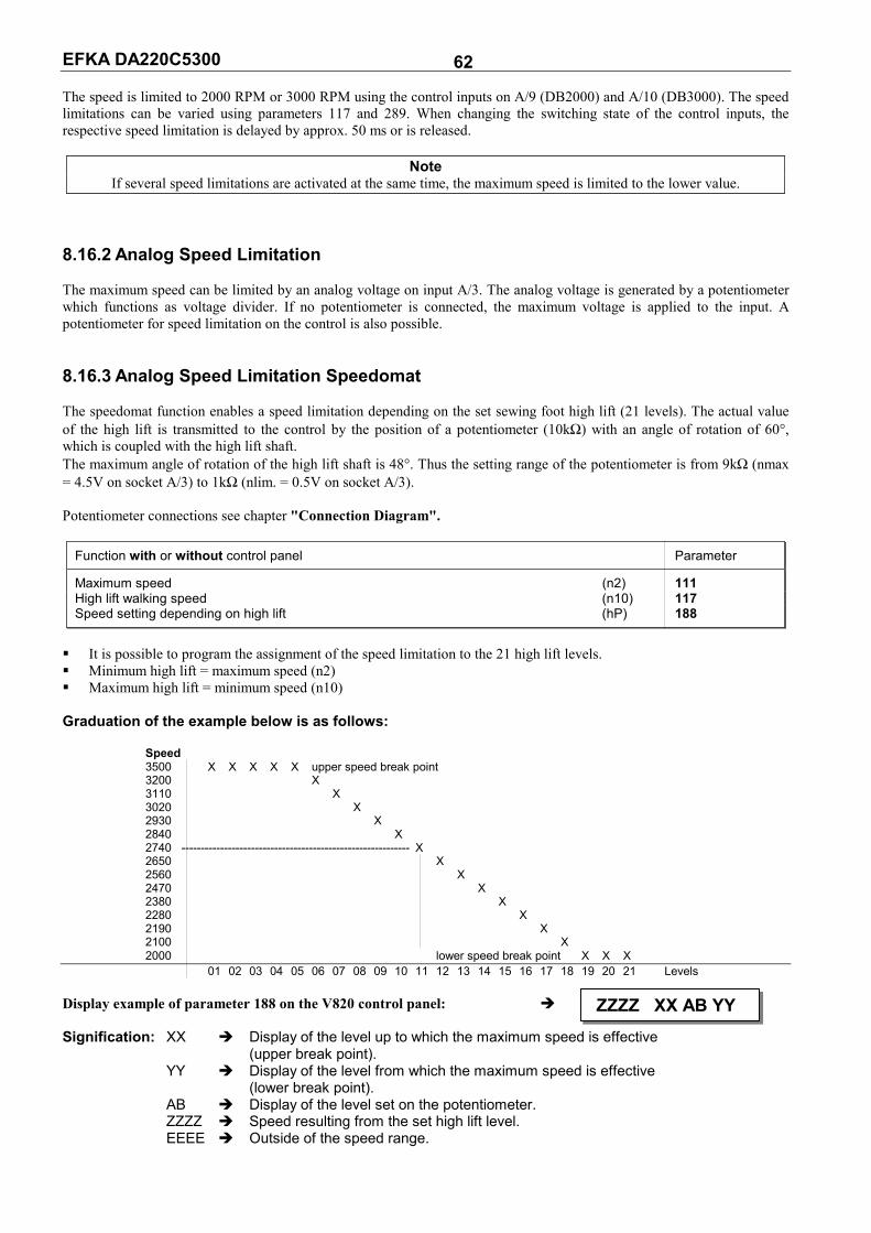
EFKA DA220C5300 62 The speed is limited to 2000 RPM or 3000 RPM using the control inputs on A/9 (DB2000) and A/10 (DB3000). The speed limitations can be varied using parameters 117 and 289. When changing the switching state of the control inputs, the respective speed limitation is delayed by approx. 50 ms or is released.
Note If several speed limitations are activated at the same time, the maximum speed is limited to the lower value.
8.16.2 Analog Speed Limitation The maximum speed can be limited by an analog voltage on input A/3. The analog voltage is generated by a potentiometer which functions as voltage divider. If no potentiometer is connected, the maximum voltage is applied to the input. A potentiometer for speed limitation on the control is also possible. 8.16.3 Analog Speed Limitation Speedomat The speedomat function enables a speed limitation depending on the set sewing foot high lift (21 levels). The actual value of the high lift is transmitted to the control by the position of a potentiometer (10kΩ) with an angle of rotation of 60°, which is coupled with the high lift shaft. The maximum angle of rotation of the high lift shaft is 48°. Thus the setting range of the potentiometer is from 9kΩ (nmax = 4.5V on socket A/3) to 1kΩ (nlim. = 0.5V on socket A/3). Potentiometer connections see chapter "Connection Diagram".
Function with or without control panel Parameter
Maximum speed (n2) 111 High lift walking speed (n10) 117 Speed setting depending on high lift (hP) 188
It is possible to program the assignment of the speed limitation to the 21 high lift levels. Minimum high lift = maximum speed (n2) Maximum high lift = minimum speed (n10) Graduation of the example below is as follows: Speed 3500 X X X X X upper speed break point 3200 X 3110 X 3020 X 2930 X 2840 X 2740 ----------------------------------------------------------- X 2650 X 2560 X 2470 X 2380 X 2280 X 2190 X 2100 X 2000 lower speed break point X X X 01 02 03 04 05 06 07 08 09 10 11 12 13 14 15 16 17 18 19 20 21 Levels Display example of parameter 188 on the V820 control panel: Signification: XX Display of the level up to which the maximum speed is effective (upper break point). YY Display of the level from which the maximum speed is effective (lower break point). AB Display of the level set on the potentiometer. ZZZZ Speed resulting from the set high lift level. EEEE Outside of the speed range.
ZZZZ XX AB YY

EFKA DA220C5300 63 8.16.4 Setting the Speed Limitation Depending on High Lift with the V820 Control Panel Determine maximum speed (n2) using parameter 111. Determine minimum speed (n10) using parameter 117. Call parameter 188. Press the E key.
Press the F2 key. Set high lift for walking foot (potentiometer on the machine) to the level up to which full speed is to be maintained
(upper break point). New value of AB is taken over to XX. Set high lift for walking foot (potentiometer on the machine) to the level from which minimum speed is to be effective
(lower break point). New value of AB is taken over to YY. Press P key once Actual parameter is displayed. / Press P key twice Exit programming. 8.16.5 Setting the Speed Limitation Depending on High Lift with the V810 Control Panel Call parameter 188. Press the E key. Press the F2 key. Actual display. Press the F2 key. Previous values are displayed. Press the F2 key. Set new value (level) with potentiometer on the machine. Press the F2 key. Press the E key. New value 08 (upper break point)
is entered. Press the F2 key.
Set new value (level) with potentiometer on the machine.
Press the F2 key. Press the E key. New value 17 (lower break point)
is entered. Press the P key once. Display of the actual parameter
number.
E F–188 hP [ ° ]
F2 ZZZZ XX AB YY
E ZZZZ XX AB YY
E ZZZZ XX AB YY
E hP [ ° ]
F2 1 1. 3 2 0 0
F2 0 5 1 9
F2 1 1. 3 2 0 0
0 8. 3 2 0 0
F2 0 5 1 9
E 0 8 0 8
F2 0 8. 3 2 0 0
1 7. 3 2 0 0
F2 0 8 0 8
E 0 8 1 7
P F - 1 8 8

EFKA DA220C5300 64 or Press the P key twice. Exit programming.
These values are saved when you start sewing. They remain in effect even after turning the machine off!
Note If you set a value on the potentiometer, which is between the actual break points, both values will be overwritten when
pressing the E key. Only after that is it possible to program new lower and/or upper break point values. 8.17 Thread Trimming Operation
Function with or without control panel Parameter
Thread trimmer On/Off (FA) 013 Thread wiper On/Off (FW) 014
Function with control panel V820
Thread trimmer On lefthand arrow On Key 5 Thread wiper On righthand arrow On Thread trimmer and thread wiper On both arrows On Thread trimmer and thread wiper Off both arrows Off
When a V820 control panel is connected, the functions can also be switched on and off using key 5.
Function with or without control panel Parameter
Trimming stitch backward (FAr) 136 Thread trimmer activation angle (iFA) 190 Thread tension release switch-off delay (FSA) 191 Switch-on delay angle of thread tension release (FSE) 192 Tread trimmer stop time (tFA) 193 Thread trimmer switch-on delay by means of increments (FAE) 194 Thread wiper time (t6) 205 Delay after thread wiping until sewing foot lifting (t7) 206
The thread trimming operation is initiated by full heelback or automatically at the end of a counted seam section or automatically by light barrier sensing after the light barrier compensating stitches. If the “trimming stitch backward” function is On (parameter 136 = 1), the backtack solenoid in the end backtack remains On until stop in position 2. When the thread trimmer is Off, the drive stops in position 2 when reaching the seam end. 8.17.1 Trimming Speed
Function with or without control panel Parameter
Trimming speed (n7) 116
8.17.2 Thread Trimmer The thread trimming signal is enabled when reaching the trimming speed with leading position 1 and is disabled after completion of the angle which can be adjusted (parameter 190), or at the very latest with the stop in position 2. A stop time for the thread trimmer, during which the drive is at standstill after reaching position 1, can be set with parameter 193. If position 2 is not reached due to a mechanical defect, the thread trimming signal is disabled after 10 sec. This way, the solenoid with 25% duty ratio will be protected against damage.
P d A 2 2 0 c P

EFKA DA220C5300 65 8.17.3 Thread Tension Release The thread tension release signal can be enabled with a time lag relative to the thread trimmer. The time lag is an angular value that is inputted in the form of increments in parameter 192. The signal is disabled in position 2. It can, however, be extended for a time that can be regulated with parameter 191. If position 2 is not reached due to a mechanical defect, the output is disabled after 10 sec. This way, the solenoid with 10% duty ratio will be protected against damage. 8.17.4 Thread Wiper The thread wiper signal is enabled for a time that can be regulated with parameter 205 after reaching position 2. After the thread wiper has been disabled, there will be a time lag that can be regulated with 206 until the sewing foot can be lifted. If the thread wiper is Off, the time lag phase for the sewing foot lift (parameter 206) will not occur. 8.17.5 Thread Clamp
Function without control panel Parameter
Thread clamp On/Off (FkL) 154 Enable thread clamp (activation angle in degrees) (K1) 155 Disable thread clamp (deactivation angle in degrees) (K1_) 156
Parameter 154 = 0 Thread clamp function Off Parameter 154 = 1 Enabling thread clamp at an angle set using parameter 155 and disabling at an angle set using
parameter 156. If parameters 155 and 156 are set to 0, the thread clamp function is Off. Parameter 154 = 2 Enabling thread clamp at 53 degrees and disabling at 224 degrees. Parameter 154 = 3 As with parameter 154=2 and additional enabling of foot lift from 53 degrees to 110 degrees at
a holding power set using parameter 334. 8.18 Seam with Stitch Counting
Function without control panel Parameter
Stitch counting On/Off (StS) 015
Function with control panel V820
Stitch counting forward On lefthand arrow On Key 2 Stitch counting backward On righthand arrow On Stitch counting Off both arrows Off
8.18.1 Stitches for Stitch Counting
Function with or without control panel Parameter
Number of stitches for a seam with stitch counting (Stc) 007
The stitch counting stitches can be programmed and varied using the above parameters directly on the control or on a connected V810/V820 control panel. For fast operator information (HIT) when using the V820 control panel, the value of the function switched on by means of key 2 can be displayed for approx. 3 seconds. During this time, the value can be varied directly by pressing key + or -.

EFKA DA220C5300 66 8.18.2 Stitch Counting Speed
Function with or without control panel Parameter
Stitch counting speed (n12) 118 Speed mode for a seam with stitch counting (SGn) 141
Speed control for stitch counting can be selected using parameter 141. Parameter 141 = 0 Execution at pedal controlled speed. Parameter 141 = 1 Execution at fixed speed n12, when pressing the pedal forward (position >1). Parameter 141 = 2 Execution at limited speed n12, when pressing the pedal forward (position >1). Parameter 141 = 3 Automatic execution at fixed speed after having pressed the pedal once. The procedure can be
interrupted by “heelback (-2)". Parameter 141 = 4 Automatic execution at fixed speed after having pressed the pedal once. The procedure can be
interrupted by “heelback (-2)". The sewing speed is reduced in each stitch depending on the actual speed (max. 11 stitches before the end of stitch counting), in order to be able to stop exactly at the end of counting. When the light barrier is on, free sewing will be performed after stitch counting. 8.18.3 Seam with Stitch Counting When Light Barrier Is On
Function with or without control panel Parameter
Light barrier On/Off (LS) 009 Stitch counting On/Off (StS) 015
Function with control panel V820
Light barrier On/Off Key 3 Stitch counting On/Off Key 2
When "stitch counting and light barrier function " is set, the number of stitches will be executed first, then the light barrier will be activated. 8.19 Free Seam and Seam with Light Barrier
Function with or without control panel Parameter
Positioning speed (n1) 110 Upper limit of maximum speed (n2) 111 Limited speed according to setting of 142 (n12) 118 Lower limit of maximum speed (n2_) 121 Speed mode free seam (SFn) 142
Speed control for the free seam and the seam with stitch counting can be selected using the speed mode. Parameter 142 = 0 Execution at pedal controlled speed Parameter 142 = 1 Execution at fixed speed n12, when pressing the pedal forward (position >1) Parameter 142 = 2 Execution at limited speed n12, when pressing the pedal forward (position >1) Parameter 141 = 3 Only for the seam with light barrier: - Automatic execution at fixed speed after having pressed the pedal once. - The seam end is initiated by light barrier. - The procedure can be interrupted by heelback (-2). - If the light barrier is not on, speed as with parameter setting 142 = 0. When using a control panel, the maximum speed is displayed after power on and thread trimming and can be varied directly by means of key +/- on the control panel. The setting range lies between the values of parameters 111 and 121.
EFKA DA220C5300 67 8.20 Light Barrier Light barrier module LSM002 is provided and is connected to socket B18. Moreover, an external light barrier can be connected to socket A/13. Both light barrier inputs initiate the same function and can be enabled and disabled with the same parameters.
Function with or without control panel Parameter
Light barrier On/Off 009
Function with control panel V820
Light barrier covered/uncovered On righthand arrow On Key 3 Light barrier uncovered/covered On lefthand arrow On Light barrier Off both arrows Off
8.20.1 Speed after Light Barrier Sensing
Function with or without control panel Parameter
Speed after light barrier sensing (n5) 114
8.20.2 General Light Barrier Functions
Function with or without control panel Parameter
Light barrier compensating stitches (for long stitches) (LS) 004 Number of light barrier seams (LSn) 006 Light barrier compensating stitches (for normal stitches) (cLS) 010 Light barrier sensing uncovered/covered (LSd) 131 Start of sewing blocked/unblocked with light barrier uncovered (LSS) 132 Light barrier seam end with thread trimming On/Off (LSE) 133
After sensing the seam end, the compensating stitches are counted at light barrier speed. Suspension of the procedure with pedal in pos. 0 (neutral). Interruption of the procedure with pedal in pos. -2. The thread trimming operation can be disabled using parameter 133, regardless of the setting of key 5 on the V820
control panel. Stop in the basic position. Programming of max. 15 light barrier seams depending on the setting of parameter 006 with stop in the basic position.
Thread trimming after the last light barrier seam. Light barrier sensing uncovered or covered at the seam end can be selected using parameter 131. Start blockage with light barrier uncovered programmable using parameter 132. Speed selection pedal controlled / n5 during the light barrier compensating stitches using parameter 192. The light barrier compensating stitches can be programmed and varied using the above parameters directly on the control or on a connected V810/V820 control panel. For fast operator information (HIT) when using the V820 control panel, the value of the function switched on by means of key 3 can be displayed for approx. 3 seconds. During this time, the value can be varied directly by pressing key + or -. 8.20.3 Reflection Light Barrier LSM002 Sensitivity setting: Set minimum sensitivity depending on the distance between light barrier and reflection area (turn potentiometer as far as possible to the left). Potentiometer directly on the light barrier module Mechanical orientation: Orientation is facilitated by a visible light spot on the reflection area.

EFKA DA220C5300 68 8.20.4 Automatic Start Controlled by Light Barrier
Function with or without control panel Parameter
Delay of automatic start (ASd) 128 Automatic start On/Off (ALS) 129 Light barrier sensing uncovered (LSd) 131 Start of sewing blocked with light barrier uncovered (LSS) 132
This function enables an automatic start of the sewing operation as soon as the light barrier senses the insertion of fabric. Prerequisites for the operation: Parameter 009 = 1 (light barrier On). Parameter 129 = 1 (automatic start On). Parameter 131 = 1 (light barrier sensing uncovered). Parameter 132 = 1 (no start of sewing with light barrier uncovered). The pedal must be kept pressed forward at the seam end. For safety reasons this function is enabled only after a normal start of sewing. The light barrier must be covered as long as the pedal is in position 0 (neutral). Then press the pedal forward. This function is disabled when the pedal is no longer pressed forward after the seam end. 8.20.5 Light Barrier Filter for Knitted Fabrics
Function with or without control panel Parameter
Number of stitches of the light barrier filter (LSF) 005 Light barrier filter On/Off (LSF) 130 Light barrier sensing uncovered or covered (LSd) 131
The filter prevents premature enabling of the light barrier function when sewing knitted fabrics. Enabling/Disabling of the filter using parameter 130 The filter is not active if parameter 005 = 0 Adaptation to the mesh is possible by varying the number of filter stitches. Knitted fabric sensing with light barrier uncovered covered, if parameter 131 = 0
Knitted fabric sensing with light barrier covered uncovered, of parameter 131 = 1 8.21 Needle Up/Down; Single Stitch The needle up/down or single stitch function can be activated by a key connected to socket A/6.
Mode for the key connected to connector A/6
Function with or without control panel Parameter
Needle up/down; single stitch (nh1) 140 1 = Needle up 2 = Needle up/down 3 = Single stitch 4 = Needle up if outside position 2
Needle up parameter 140 = 1 When the key is pressed, the drive runs from position 1 to position 2. If the drive is outside position 1, it does not move for safety reasons. If the key is pressed and the sewing foot lifted, the sewing foot will be lowered before the drive runs to position 2. The function is blocked after power On until sewing is started. Needle up/down parameter 140 = 2 When the key is pressed, the drive runs from position 1 to position 2 or from position 2 to position 1. If the drive is outside the two positions, it runs to the next possible position. After power On, the drive runs to the next position identified. Single stitch parameter 140 = 3 When the key is pressed, the drive performs one rotation from the basic position. If the drive is not in the basic position, it runs there when pressing the key. It performs one complete rotation each time the key is pressed again. Needle in position 2 parameter 140 = 4 When the key is pressed, the drive runs to position 2, independently of its present position. This function is also possible after power On.

EFKA DA220C5300 69 8.22 F1/F2 Function Key Assignment on the V810/V820 Control Panels
Functions Parameter
Selection of input function on the (A) key "F1" on the V810/V820 control panels (tF1) 293 Selection of input function on the (B) key "F2" on the V810/V820 control panels (tF2) 294
The following functions are possible using parameters 293 and 294: 293/294 = 0 Input function blocked 293/294 = 1 Needle up/down: Upon pressing the key, the drive runs from position 1 to position 2 or from position 2 to position 1. If the drive is not in the stop position, it runs to the preselected basic position. 293/294 = 2 Needle up: Upon pressing the key, the drive runs from position 1 to position 2. 293/294 = 3 Single stitch (basting stitch): Upon pressing the key, the drive performs one rotation from position 1 to position 1. If the drive is in position 2, it runs to position 1 upon pressing the key and from position 1 to position 1 each time the key is pressed again. 293/294 = 4 Full stitch: Upon pressing the key, the drive performs a full rotation depending on the stop position. 293/294 = 5 Needle to position 2: If the drive is not in position 2, it runs to position 2 upon pressing the key. 293/294 = 6 Output A if parameter 250 <0 293/294 = 7 Output B if parameter 250 <0 293/294 = 8 Handwheel runs in the direction of rotation 293/294 = 9 Handwheel runs in the opposite direction of rotation 293/294 = 10...12 No function 293/294 = 13 High lift for walking foot operational mode not stored: The signal “high lift for walking foot” is issued as long as the key is pressed down, and the drive runs with speed limitation (n10). 293/294 = 14 High lift for walking foot operational mode stored /flip-flop 1: The signal “high lift for walking foot” is issued upon briefly pressing the key, and the drive runs with speed limitation (n10). The operation is disabled upon pressing the key again. 293/294 = 15 No function 293/294 = 16 Intermediate backtack: Upon pressing the key, the backtack will be enabled anywhere in the seam and at standstill of the drive. 293/294 = 17 Backtack suppression / recall: Upon pressing the key, the backtack will be suppressed or recalled once. 293/294 = 18 No function 293/294 = 19 Reset bobbin thread monitor: After inserting a full bobbin, the stitch counter is set to the value determined using parameter 085. 8.23 Signals A1 and A2
Function with control panel V820
Signal A1 On lefthand arrow On Key 8 Signal A2 On righthand arrow On Signals A1 and A2 On both arrows On Signals A1 and A2 Off both arrows Off
After slide-in strip 6 has been inserted into the V820 control panel and parameter 292 set to “6”, signals A1 and A2 can be assigned to a seam using key 8. The parameters described below determine the moment in which the signals are assigned in the seam and how long these signals are active. The example below illustrates the various possibilities (if parameter 320 = 0).
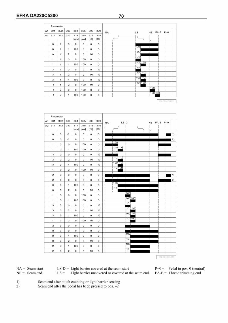
EFKA DA220C5300 70
1 12
3
3 1
1
11
2
2
1
1 02
03 1
Parameter
301
311A2
A1
0
0 11
1 0
1 1 0
1 1 1
0 1 2
303
313312
302
10
10
0
0
0
0
100100
0 100
0
0 0
100
0 100
0 0
0
0
10
10
0
10
318[St]
308
0
0
0
0
10
[ms] [ms]
0100
0 0
0 100
100 100
0 0
314 315
304 305
[St]
0
0
0
0
0
319
309NA
100
100
NE
10
10 10
10100
10 100
100 100
100
10
100
LS
0256/BILD4
100
P=0FA-E
32 2
32 1
2
133
3
30
0
1
0
1 3
32 0
30 2
10
0
0
0
0
10
10
0
0 0
100 0
100
100 0
0
100 0
0
0
0 0
00
0
0
10
0
0
0
0
0
0 0 1
0 0 2
031
3
33 0
33 2
1 1
3
3
0
10
2
1 0 2
2 0 0
2 0 0
301
Parameter
311
A1
A2
0
0
1
0 0
0 0
0 0
1 10
3 0 0
302
312
303
313
10
0
10
0
10
0
0
0
0
10
0
100 0
0 0
0 100
100100
0 0
0 0
0 0
100 0
1000
0 0
0 0
0
0
0
10
10
0
10
10
0
0
0
318[St]
308
0
0
0
0
0
[ms] [ms]
0 0
0 0
0 100
100100
0 0
314 315
304 305
[St]
0
0
0
0
10
NA319
309
100 10
100
10
10
100
10
100
0256/BILD3
NE
10 10
10
100
100
10
10
10
100 10
100
100
100
10
100
100100
10
LS-D
1)
2)
P=0FA-E
1)
2)
NA = Seam start LS-D = Light barrier covered at the seam start P=0 = Pedal in pos. 0 (neutral) NE = Seam end LS = Light barrier uncovered or covered at the seam end FA-E = Thread trimming end 1) Seam end after stitch counting or light barrier sensing 2) Seam end after the pedal has been pressed to pos. –2

EFKA DA220C5300 71 Different power transistors can be selected using parameter 300 for signal A1 and parameter 310 for signal A2. Parameter 300/310 0 No function 1 Signal A1 / A2 at output M1 2 Signal A1 / A2 at output M2 3 Signal A1 / A2 at output M3 4 Signal A1 / A2 at output M4 5 Signal A1 / A2 at output M5 6 Signal A1 / A2 at output M6 7 Signal A1 / A2 at output M7 8 Signal A1 / A2 at output M8 9 Signal A1 / A2 at output M9 10 Signal A1 / A2 at output M10 11 Signal A1 / A2 at output M11 12 Signal A1 / A2 at output VR It is possible to select using parameter 301 for signal A1 and parameter 311 for signal A2, whether the signals On until the seam end or during a programmable time. Parameter 301/311 0 Signal A1 / A2 active until seam end 1 Signal A1 / A2 effective during a programmable time It is possible to select using parameter 302 for signal A1 and parameter 312 for signal A2, whether the signals shall be effective at the seam start, after light barrier sensing or at the seam end. Parameter 302/312 0 Signal A1 / A2 starts at the beginning of the seam 1 Signal A1 / A2 starts after light barrier sensing 2 Signal A1 / A2 starts at the seam end It is possible to select using parameter 303 for signal A1 and parameter 313 for signal A2, whether the signals shall be activated with or without delay. Parameter 303/313 0 Signal A1 / A2 activated without delay time 1 Signal A1 / A2 activated with a delay time The delay times can be selected separately for signal A1 using parameter 304 and for signal A2 using parameter 314. The ON periods can be selected separately for signal A1 using parameter 305 and for signal A2 using parameter 315. The speed mode can be set separately for signal A1 using parameter 306 and for signal A2 using parameter 316. The speed limitation is effective only when the respective signal is On. Parameter 306/316 0 Pedal controlled speed 1 Limited to speed n9 (parameter 288) when signal is issued 2 Limited to speed n11 (parameter 289) when signal is issued The signals can be enabled or disabled separately for signal A1 using parameter 307 and for signal A2 using parameter 317. It is possible to select using parameter 308 for signal A1 and parameter 318 for signal A2, whether the signals shall be activated with or without delay stitches. Parameter 308/318 0 Signal A1 / A2 activated without delay stitches 1 Signal A1 / A2 activated with delay stitches Separate stitch counts can be selected for signal A1 using parameter 309 and for signal A2 using parameter 319. The switch-off moment for signals A1 and A2 can be set using parameter 320. Parameter 320 0 Signals effective until seam end 1 Signals effective until pedal has been pressed to pos. 0 (neutral)
When using the V820 control panel, direct access by means of the function key (key 9) is possible!
Function with control panel Parameter
Signal A1 and/or A2 On/Off with slide-in strip 1...4 (-F-) 008 = 5 (lefthand arrow = A1, righthand arrow = A2)
8.24 Signal Output Position 1 Transistor output with open collector Signal whenever the needle is in the slot between position 1 and 1A Independent of sewing, thus also when turning the handwheel manually Suitable e. g. for the connection of a counter An inverted signal is issued at socket A/20

EFKA DA220C5300 72 8.25 Signal Output Position 2 Transistor output with open collector Signal whenever the needle is in the slot between position 2 and 2A Independent of sewing, thus also when turning the handwheel manually Suitable e. g. for the connection of a counter An inverted signal is issued at socket A/21 8.26 Signal Output 512 Impulses per Rotation Transistor output with open collector Signal whenever a generator slot of the position transmitter is sensed 512 impulses per rotation of the handwheel Independent of sewing, thus also when turning the handwheel manually Suitable e. g. for the connection of a counter An inverted signal is issued at socket A/22 8.27 Actuator The commands for the sewing operation are input by means of the actuator, which is connected to the pedal. Instead of the built-on actuator another actuator can also be connected to socket B80.
Table: Coding of the Pedal Steps
Pedal step D C B A
-2 H H L L Full heelback (e. g. initiating the seam end) -1 H H H L Slight heelback (e. g. sewing foot lifting) 0 H H H H Pedal in pos. 0 (neutral) ½ H H L H Pedal slightly forward (e. g. sewing foot lowering) 1 H L L H Speed stage 1 (n1) 2 H L L L Speed stage 2 3 H L H L Speed stage 3 4 H L H H Speed stage 4 5 L L H H Speed stage 5 6 L L H L Speed stage 6 7 L L L L Speed stage 7 8 L L L H Speed stage 8 9 L H L H Speed stage 9 10 L H L L Speed stage 10 11 L H H L Speed stage 11 12 L H H H Speed stage 12 (n2) Pedal fully forward
EB.. Actuator 2) Nominal voltage 5V, Imax = 20 mA

EFKA DA220C5300 73
Function with or without control panel Parameter
Speed stage graduation (nSt) 119
The pedal characteristics (speed change from stage to stage) can be varied. Possible characteristic curves: - linear - progressive - highly progressive 8.28 Acoustic Signal
Function with control panel Parameter
Audible signal On/Off (AkS) 127
An audible signal which sounds in the following cases can be enabled using parameter 127: When the machine run blockage is On. 8.29 Master Reset
Recovery of factory settings. Press the "P" key and turn power on Input code number "190" Press the "E" key Parameter 100 appears on the display Press the "E" key The parameter value is shown on the display Set to "170" using the “+” key Press the "P" key twice Turn power off Turn power on. All parameters, except 111, 161, 170, 171, 190...193, have been reset to their factory settings. 9 Signal Test
Function with or without control panel Parameter
Input and output test (Sr4) 173
Function test of external inputs and transistor power outputs with connected actuators (e.g. solenoids and solenoid valves). 9.1 Signal Test Using the Incorporated Control Panel or the V810/V820 Input Test: Select parameter 173. Control: Functions of signals “light barrier, sensor (IPG... or HSM...), generator impulse
1 and 2, positions 1 and 2” can be checked directly and indicated by LEDs 3...8. Inputs in1...in10 are displayed individually. Several switches and/or keys must not be actuated at the same time. If several keys and/or switches are actuated at the same time, e.g. in3, in5, in6, in7, the least significant input will be displayed, e.g. in3.
G1
G2
KL2462
P
E
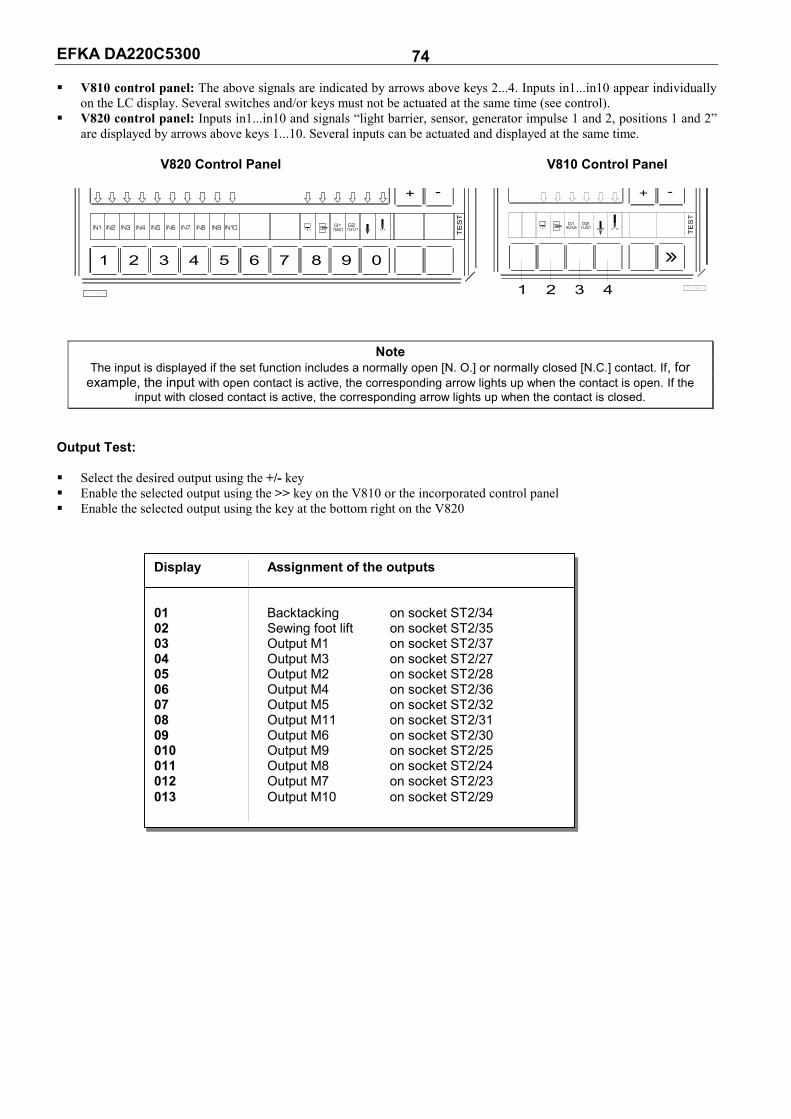
EFKA DA220C5300 74 V810 control panel: The above signals are indicated by arrows above keys 2...4. Inputs in1...in10 appear individually
on the LC display. Several switches and/or keys must not be actuated at the same time (see control). V820 control panel: Inputs in1...in10 and signals “light barrier, sensor, generator impulse 1 and 2, positions 1 and 2”
are displayed by arrows above keys 1...10. Several inputs can be actuated and displayed at the same time. V820 Control Panel V810 Control Panel
O
+ - + -
Note The input is displayed if the set function includes a normally open [N. O.] or normally closed [N.C.] contact. If, for
example, the input with open contact is active, the corresponding arrow lights up when the contact is open. If the input with closed contact is active, the corresponding arrow lights up when the contact is closed.
utput Test:
Select the desired output using the +/- key Enable the selected output using the >> key on the V810 or the incorporated control panel Enable the selected output using the key at the bottom right on the V820
Display Assignment of the outputs 01 Backtacking on socket ST2/34 02 Sewing foot lift on socket ST2/35 03 Output M1 on socket ST2/37 04 Output M3 on socket ST2/27 05 Output M2 on socket ST2/28 06 Output M4 on socket ST2/36 07 Output M5 on socket ST2/32 08 Output M11 on socket ST2/31 09 Output M6 on socket ST2/30 010 Output M9 on socket ST2/25 011 Output M8 on socket ST2/24 012 Output M7 on socket ST2/23 013 Output M10 on socket ST2/29
IN3
1
IN2IN1
42 3 5 6
IN8IN7IN6IN5IN4 IN10IN9
987 0
G2G1
TE
ST
KL2460
G1 G2
TE
ST
1 2 3 4 KL2461
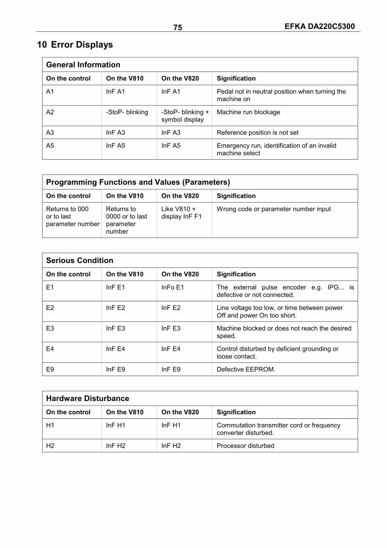
EFKA DA220C5300 75 10 Error Displays
General Information
On the control On the V810 On the V820 Signification
A1 InF A1 InF A1 Pedal not in neutral position when turning the machine on
A2 -StoP- blinking -StoP- blinking + Machine run blockage symbol display
A3 InF A3 InF A3 Reference position is not set
A5 InF A5 InF A5 Emergency run, identification of an invalid machine select
Programming Functions and Values (Parameters) On the control On the V810 On the V820 Signification
Returns to 000 Returns to Like V810 + Wrong code or parameter number input or to last 0000 or to last display InF F1 parameter number parameter number
Serious Condition
On the control On the V810 On the V820 Signification
E1 InF E1 InFo E1 The external pulse encoder e.g. IPG... is defective or not connected.
E2 InF E2 InF E2 Line voltage too low, or time between power Off and power On too short.
E3 InF E3 InF E3 Machine blocked or does not reach the desired speed.
E4 InF E4 InF E4 Control disturbed by deficient grounding or loose contact.
E9 InF E9 InF E9 Defective EEPROM.
Hardware Disturbance
On the control On the V810 On the V820 Signification
H1 InF H1 InF H1 Commutation transmitter cord or frequency converter disturbed.
H2 InF H2 InF H2 Processor disturbed

EFKA DA220C5300 78 11 Operating Elements of the V810 Control Panel
P
+
A1 2 3 4
variocontrol 810
KL2185B
-
1
E
The V810 control panel is supplied with slide-in strip no. 1 above the keys. For different functions the strip can be replaced with another one supplied with the control panel. Set parameter 291 in this case. See also V810 / V820 instruction manual!
Function Assignment to the Keys Key P = Call or exit of programming mode Key E = Enter key for modifications in the programming mode Key + = Increase of the value indicated in the programming mode Key - = Decrease of the value indicated in the programming mode Key 1 = Start backtack SINGLE / DOUBLE / OFF Key 2 = End backtack SINGLE / DOUBLE / OFF Key 3 = Automatic sewing foot lift after thread trimming ON / OFF Automatic sewing foot lift at stop in the seam ON / OFF Key 4 = Basic position needle down (POSITION 1) / needle up (POSITION 2) Key A = Key for intermediate backtack (Different input functions can be assigned to the A key using parameter 293) Key B = Key for needle up/down or shift key in the programming mode (Different input functions can be assigned to the B key using parameter 294)

EFKA DA220C5300 79 12 Operating Elements of the V820 Control Panel
variocontrol 820
P E
KL2186
41 2 3
B
R
85 6 7 9 0
A
+ -
F 1
The V820 control panel is supplied with slide-in strip no. 1 above the keys. For different functions the strip can be replaced with another one supplied with the control panel. Set parameter 292 in this case. See also V810 / V820 instruction manual!
Function Assignment to the Keys Key P = Call or exit of programming mode Key E = Enter key for modifications in the programming mode Key + = Increase of the value indicated in the programming mode Key - = Decrease of the value indicated in the programming mode Key 1 = Start backtack SINGLE / DOUBLE / OFF Key 2 = Stitch counting seam FORWARD / BACKWARD / OFF Key 3 = Light barrier function COVERED-UNCOVERED / UNCOVERED-COVERED / OFF Key 4 = End backtack SINGLE / DOUBLE / OFF Key 5 = THREAD TRIMMER / THREAD TRIMMER + THREAD WIPER / OFF Key 6 = Automatic sewing foot lift after thread trimming ON / OFF Automatic sewing foot lift at stop in the seam ON / OFF Key 7 = Basic position needle down (POSITION 1) / needle up (POSITION 2) Key 8 = Bobbin thread monitor ON / OFF Key 9 = Function key - programmable Key 0 = Teach-in / execution of 99 possible seam sections Key A = Key for backtack suppression/recall (Different input functions can be assigned to the A key using parameter 293) Key B = Key for needle up/down or shift key in the programming mode (Different input functions can be assigned to the B key using parameter 294)
Special Key Assignment for HIT After having pressed key 1, 2, 3, 4 or 9, the following can be varied using the +/- key: Key 1 = Number of stitches of the selected start backtack Key 2 = Number of stitches of the seam with stitch counting Key 3 = Number of light barrier compensating stitches Key 4 = Number of stitches of the selected end backtack Key 9 = Number of stitches or On/Off of the programmed function
FRANKL & KIRCHNER GMBH & CO KG SCHEFFELSTRASSE 73 – D-68723 SCHWETZINGEN TEL.: +49-6202-2020 – TELEFAX: +49-6202-202115 email: [email protected] – http://www.efka.net
OF AMERICA INC. 3715 NORTHCREST ROAD – SUITE 10 – ATLANTA – GEORGIA 30340 PHONE: (770) 457-7006 – TELEFAX: (770) 458-3899 – email: [email protected]
ELECTRONIC MOTORS SINGAPORE PTE. LTD. 67, AYER RAJAH CRESCENT 05-03 – SINGAPORE 139950 PHONE: +65-67772459 – TELEFAX: +65-67771048 – email: [email protected] 5(8)-080104 J (402264 EN)


