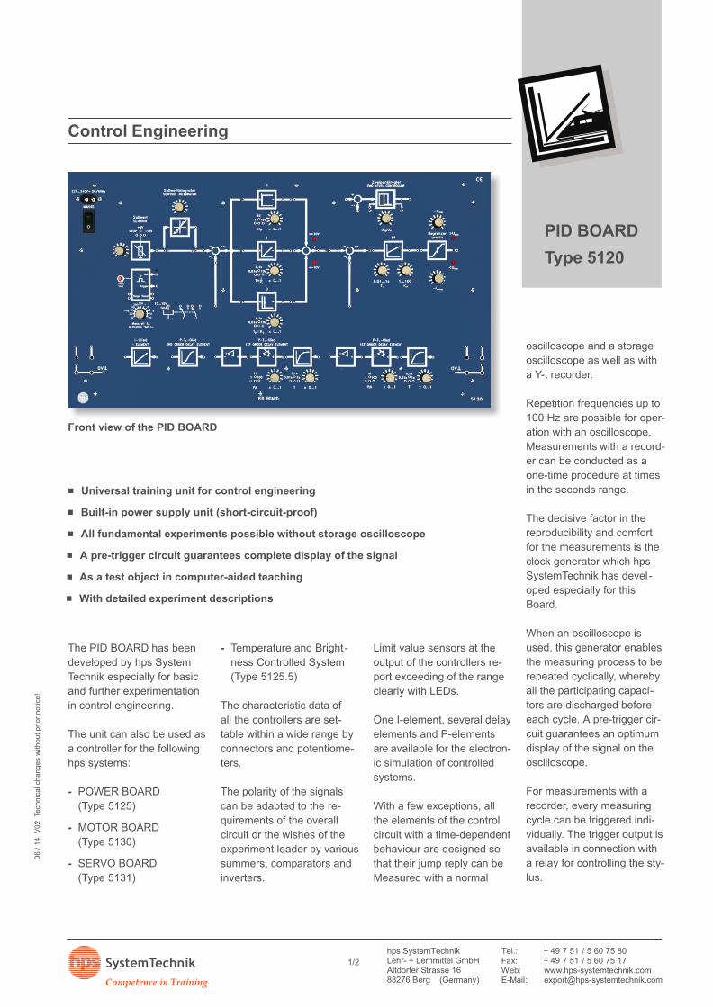
. Universal training unit for control engineering. Built-in power supply unit (short-circuit-proof). All fundamental experiments possible without storage oscilloscope. A pre-trigger circuit guarantees complete display of the signal. As a test object in computer-aided teaching. With detailed experiment descriptions
- The front panel of the PID BOARD is made of 5 mm thick lam-inate, matt blue in colour with white engraving representing thebuilt-in function groups.
- The rear of the Board is protected with a grey plastic cover.
Its shape allows the Board to be placed at an ergonomicallyfavourable angle for example on a table.
Dimensions and weights
- Board version (Type 5120):
532 x 297 x 110 mm (w x h x d)weight: ca. 3.35 kg
- Box version, consisting of:
PID BOARD (Type 5120) andBox (Type 5120.20): 580 x 450 x 155 mmtotal weight: approx. 6.1 kg
Technical Data
www.hps-systemtechnik.com
Competence in Training
SystemTechnik 2/2
PID BOARD
Type 5120
With the POWER BOARD,
hps SystemTechnik offers a
demonstration and training
system with which experi-
ments covering the whole
field of power electronics can
be conducted.
Experiments on the sin-gle-phase AC supply
- The uncontrolled
half-wave rectifier
- The uncontrolled bridge
rectifier
- The half-controlled bridge
rectifier
- The fully controlled bridge
rectifier
- The line-commutated
inverter
- Two fully controlled bridge
rectifiers, antiparallel with
circulating current-free wir-
ing and optical indication
by 2 LEDs
- Pulse group control
Experiments on thethree-phase supply
- The uncontrolled rectifier
(M3)
- The uncontrolled rectifier
(B6)
- The controlled rectifier
(M3)
- The controlled rectifier
(B6)
Experiments on theDC supply
- Basic pulse width modula-
tion (PWM) circuits
- PWM with H-circuit,
DC-evaluated
- PWM with H-circuit,
Experiments with the
sine-evaluated
GTO (Gate-Turn-Off)
- Firing pulse conditioning
for the GTO
- The GTO as a DC actuator
The POWER BOARD con-
tains ohmic, inductive and
capacitive loads for conduct-
ing the experiments men-
tioned above.
Bridgeable shunts are inte-
grated in all the important
load current branches for
measuring the currents.
In the phase gate control
no. I, all the important test
points in the circuit are ac-
cessible at jacks. This circuit
can be used both in single-
pulse and multi-pulse mode.
Phase gate control no. II has
an additional input for opera-
tion with negative setpoint.
This makes it possible to
simulate a four-quadrant
drive in conjunction with the
controlled system MOTOR
BOARD (Type 5130).
All firing pulse outputs of the
phase gate controls are elec-
trically isolated with firing
transformers. In this way,
Power Electronics / Control Engineering
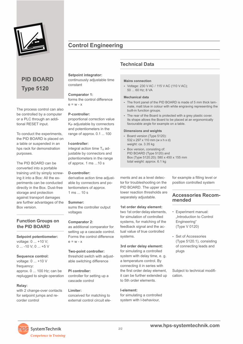
. The whole power electronics on one Board. With built-in three-phase source. Connection field for Temperature and Brightness Controlled System. All experiments with protective low voltage (12 V). Four-quadrant operation with H-circuit (MOS-FET) or antiparallel thyristor bridges. Can be combined with PID BOARD, MOTOR BOARD and STEPPING BOARD
Mechanical play in the drive (realised electronically)
Actual value measurement (By potentiometer)
Mechanical range of rotation: 320° without stop-
- Linearity tolerance: +/-1.5 %
- Resistance: 5 kW (+/-15 %)
Actual value output
Decoupled through amplifier and inverted for protection of motorPotentiometer- Output voltage: 0 ... 10 V
- Output resistance: 200 W
2 outputs (U1 / U )2
Output voltage:TTL, 90° offset, decoupled by TTL component. The outputsignals are incremental and only available when the reflectivesensors are plugged in (Type 5131.5).
Decoding logic
Indicated by two LEDs for right- and left-hand rotation.The logical 1 or 0 states can be tapped additionally at 2 mmjacks; TTL signal; decoupled by TTL component.The signals are available when both reflective sensors areplugged (Type 5131.5).
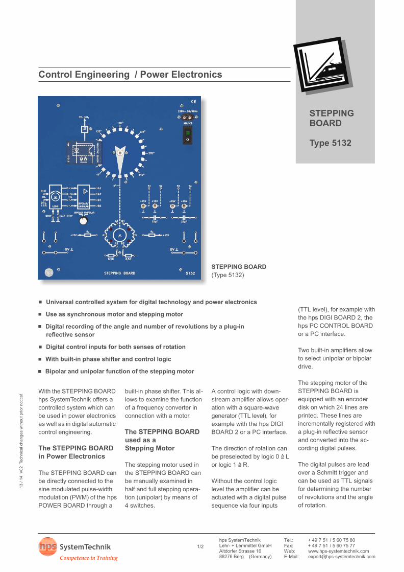
. Universal controlled system for digital technology and power electronics. Use as synchronous motor and stepping motor. Digital recording of the angle and number of revolutions by a plug-in
reflective sensor. Digital control inputs for both senses of rotation. With built-in phase shifter and control logic. Bipolar and unipolar function of the stepping motor
Digital Technoloy
Technical Data
Mains connection
Voltage: 230 V AC / 115 V AC (110 V AC);-20 VA; 50 ... 60 Hz
Motor
Stepping motor, 2-phase-- Rated voltage: 12 V
- Current consumption: max. 0.4 A per phase
Resonant frequency: 15 Hz ... 35 Hz-
Voltage supply
+15 V in unipolar mode, for each phase-
Encoder disk-1Speed: 300 min-
- Resolution: 24 pulses (lines) / revolution
Plug-in field (4 mm jacks)
for the use of the Reflective Sensor (Type 5131.5) with theencoder disk
Output (U )1
Output voltage: TTL, decoupled through TTL module.The output signal is incremental and only existing with pluggedReflective Sensor.
Adapter fields
The adapter fields serve for change-over from 4 mm to 2 mm plugconnections and to plug-in adapters (BNC jack 4 mm plugs).
Amplifier
All inputs: TTL level-
Control logic
CLK input: TTL level-- Input below: TTL level
logic 1 =̂ clockwiselogic 0 =̂ anticlockwise
Dimensions and weight
- 266 x 297 x 90 mm (w x h x d);weight: approx. 1.2 kg
Subject to technical modifications.
To conduct the experiments,
the STEPPING BOARD is
placed on a table or suspen-
ded in an hps bench rack for
demonstration purposes.
Mechanical Data
Thick laminate, matt blue in colour with white engraving
representing the built-in function groups.
The rear of the Board is protected with a grey plastic cover.
Its shape allows the Board to be placed at an ergonomically
favourable angle for example on a table.
Accessories Included
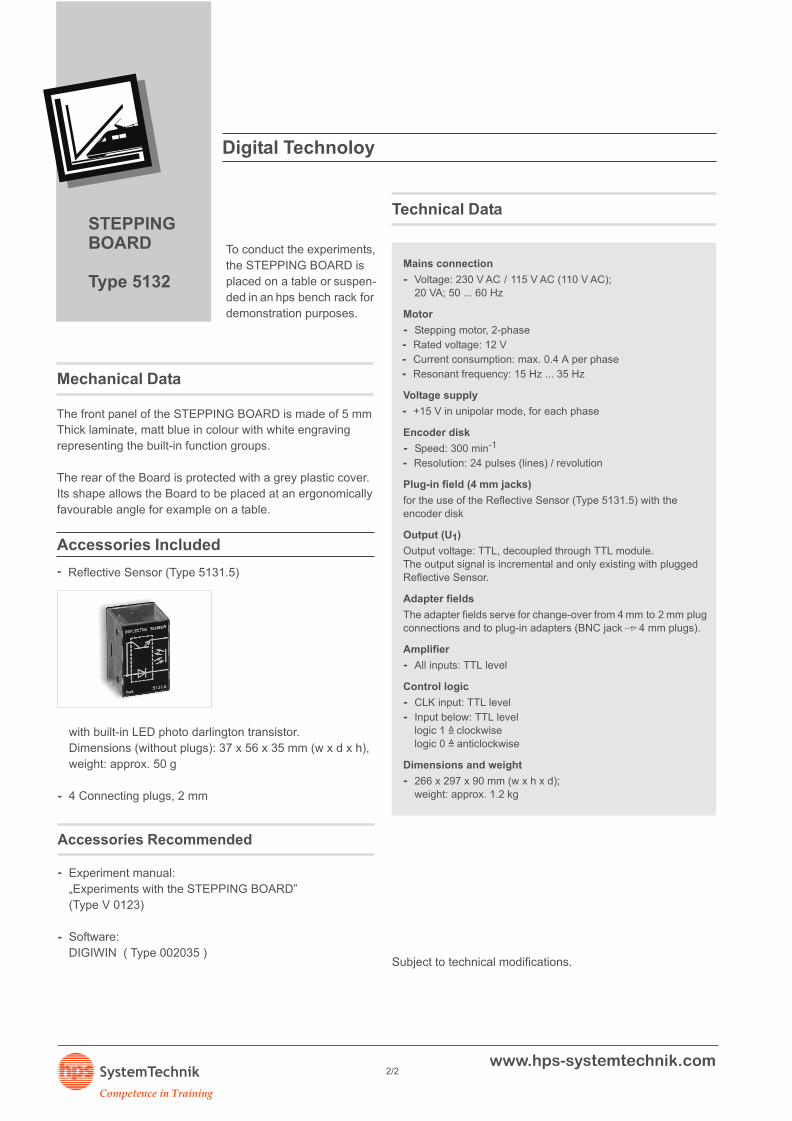
Reflective Sensor (Type 5131.5)
with built-in LED photo darlington transistor.
Dimensions (without plugs): 37 x 56 x 35 mm (w x d x h),
weight: approx. 50 g
-
-
4 Connecting plugs, 2 mm
Accessories Recommended
Experiment manual:
„Experiments with the STEPPING BOARD”
(Type V 0123)
-
-
Software:
DIGIWIN ( Type 002035 )
www.hps-systemtechnik.com
Competence in Training
SystemTechnik 2/2
STEPPINGBOARD
Type 5132
The front panel of the STEPPING BOARD is made of 5 mm
The PC CONTROL BOARD
PCI serves as an interface
between a commercially
available PC (IBM-compatible)
and the Boards for digital
technology, control engineer-
ing and measuring contained
in the hps program.
Three software programs
are offered for the PC CON-
TROL BOARD PCI:
- DIGIwin
- MESSwin
- WinFACT
DIGIWINcan be used to de -
sign, simulate and analyse
any digital circuits. The pro-
gram provides numerous
components for this purpose.
External devices such as the
hps DIGI BOARD 2 can be
included in the simulation in
connection with the PC
CONTROL BOARD PCI.
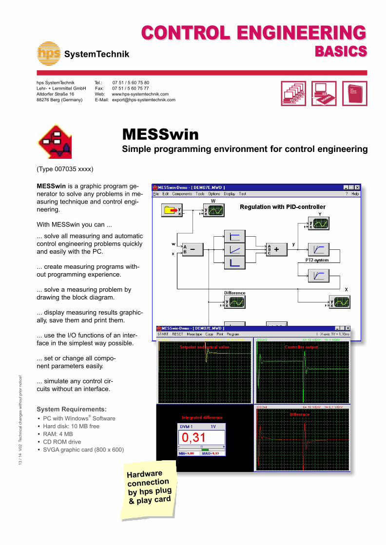
MESSwinis an object-
oriented programming envi-
ronment for tasks in the field
of measuring, controlling and
regulating.
MESSwin can be used for
example in connection with
the PC CONTROL BOARD
PCI for position control with
the hps SERVO BOARD or
for speed control with the
hps MOTOR BOARD.
WinFACT is an innovative
modular software program
for analysis, synthesis and
simulation in control engi-
neering with the simulation
system BORIS as its basic
module.
It can be expanded by a
fuzzy shell for analyzing
fuzzy systems. The fuzzy
systems generated with
FLOP can be integrated in
the block oriented simulation
of BORIS.
WinFACT was especially de-
signed for use in vocational,
technical and academic
schools, but is also appropri-
ate for use in industry and
research.
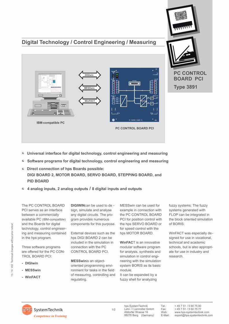
Digital Technology / Control Engineering / Measuring
Direct connection of hps Boards possible:
Software programs for digital technology, control engineering and measuring
Universal interface for digital technology, control engineering and measuring
DIGI BOARD 2, MOTOR BOARD, SERVO BOARD, STEPPING BOARD, and
PID BOARD
/4 analog inputs, 2 analog outputs 8 digital inputs and outputs
Output voltage: +10 V; 20 mA-e. g. for SERVO BOARD (Type 5131)
PCI-I/O Card (hps Type 2736)
PCI slot (5 V)-
Adapter fields
The adapter fields serve for change-over from 4 mm to 2 mmplug connections and to plugin adapters (BNC jack 4 mmplugs). Wiring of the inputs and outputs of the PC CONTROLBOARD PCI via 2 mm jacks.
Dimensions and weight
- 266 x 297 x 90 mm (w x h x d); weight: approx. 1.5 kg
To conduct the experiments, the PC CONTROL BOARD PCI isplaced on a table or suspended in an hps bench rack for demon-
Stration purposes.
Subject to technical modifications.
Mechanical Data
The front panel of the PC CONTROL BOARD PCI is made of
5 mm thick laminate, matt blue in colour with white engraving
representing the built-in function groups.
The rear of the Board is protected with a grey plastic cover.
Its shape allows the Board to be placed at an ergonomically
favourable angle for example on a table.
Accessories Required
IBM-compatible PC with Windows 95 / 98 / NT 4.0 / 2000 /
ME oder XP, free slot for PC Plug-in Card (5 V)
-
-
PCI-I/O Card (hps Type 2736) with Connecting lead
Available Software
DIGIwin:
Simulation software for digital technology
-
-
MESSwin:
Object-oriented programming environment for tasks in the
field of measuring, controlling and regulating.
- WinFACT:
Software for analysis, synthesis und simulation in the
control engineering
www.hps-systemtechnik.com
Competence in Training
SystemTechnik 2/2
PC CONTROLBOARD PCI
Type 3891
hps SystemTechnik has
designed the Module System
for Control Engineering spe-
cially for basic and further
experiments in control engi-
neering.
It consists of plug-in modules
which are plugged into the
- UNIVERSAL BOARD 1
(Type 8175) or the
- UNIVERSAL BOARD 2
(Type 8176)
for conducting experiments.
- UNIVERSAL ASSEMBLY
BOARD (Type 1012.1)
or
- UNIVERSAL ASSEMBLY
BOARD (Type 1012.2)
can be used to set up the
experiments instead of the
UNIVERSAL BOARDs.
The Module System for Con-
trol Engineering can also be
used in connection with
other hps systems such as:
- POWER BOARD
(Type 5125)
- MOTOR BOARD
(Type 5130)
- Temperature and Bright-
ness Controlled System
(Type 5125.5)
- SERVO BOARD
(Type 5131)
To conduct the experiments,
the Boards or Assembly
Boards can be placed at an
ergonomically favourable
angle on the table or sus-
pended in a demonstration
rack.
The modules are wired with
2 mm connecting leads and
plugs.
Control Engineering
. Modular training system for fundamental control engineering. Clear experiment set-up because only the modules required for the
experiment are plugged in. Short experiment set-up times due to central operating voltage supply. Individual combination possibilities. Extendible with MOTOR BOARD, SERVO BOARD and Temperature and
The module housings consist of a top section made of unbreak-able transparent plastic and a sturdy bottom section made ofblack, glass-fibre reinforced plastic. The top and bottom sectionsare held together by two snap-action catches; these enable thehousing to be opened quickly and easily.There are three gold-plated laminated plugs in the base of thehousing to plug the modules into the Boards or Assembly Boards.The power supply is fed to the modules through these plugs also.The circuit symbol of the function group contained in the moduleis printed in white on the front.
Other technical data
Plug diameter: 4 mm (arrangement in 19 mm grid)-- Operating voltage: +/-15 V DC
- All modules with reverse polarity protection
All IC components inserted in sockets-Housing dimensions: 75 x 56 x 35 mm (- w x d x h)
- Weight: approx. 0.1 kg
Technical Data of the Modules for
Control Engineering
Apart from a few exceptions,
(Types 9501 ... 9519)
all the modules are designed
with time-dependent behav-
iour so that their jump
reply can be measured with
a standard oscilloscope, a
storage oscilloscope and
with a y-t recorder.
Repetition frequencies up to
about 125 Hz are possible.
Measurements with a re-
corder can be made as a
single process at times in the
seconds range.
The process control devel-
oped by hps SystemTechnik
specially for the Module Sys-
tem for Control Engineering
is decisive for the reproduci-
bility and comfort of the mea-
surements.
When using an oscilloscope,
this control system allows
the measuring process to be
repeated cyclically, whereby
all the capacitors involved
are discharged before every
cycle.
A pre-trigger circuit provides
an optimum signal represen-
tation on the oscilloscope.
Every measuring cycle can
be triggered singly for mea-
surements with a recorder.
The trigger output is avail-
able in connection with the
Relay (Type 9131.2) for con-
trolling the nib.
The process control can also
be controlled by a PC or
PLC through an additional
RESET input.
hps SystemTechnik offers 16 modules for conducting
experiments in control engineering.
These are illustrated below with designation, technical data
and type number.
General Technical Data
www.hps-systemtechnik.com
Competence in Training
SystemTechnik 2/6
ModulsystemControlEngineering
Series 9500
Control Engineering
Modules for Control Engineering
Type 9501 Type 9502
Type 9503 Type 9504
Type 9505 Type 9506
PI-Controller Type 9508Proportional action factor K : approx. 1 ... 100;P
integration time T : approx. 0.01 s ... 1s;I
current consumption: max. approx. 30 mA
D-Controller Type 9507: 0 ... 0.01 s; 0 ... 0.1 s; 0 ... 10 s;DDifferentiation times T
current consumption: max. approx. 10 mA
Type 9507 Type 9508
P-Controller Type 9505: 0 ... 1; 0 ... 10; 0 ... 100;PProportional action factors K
current consumption: max. approx. 20 mA
I-Controller Type 9506: 0 ... 0.01 s; 0 ... 0.1 s; 0 ... 10 s;IIntegration times T
current consumption: max. approx. 15 mA
Comparator Type 9504The comparator is structured as an inverting adder. It forms the difference ofboth input signals, the result is inverted.current consumption: max. 20 mA
Sequence Control Type 9502
Output voltage: +12 V (squarewave); frequency: 0.1 ... 2.1 Hz/1.9 ... 125 Hz;with single trigger and repetitive trigger;current consumption: max. approx. 80 mA
Setpoint Integrator Type 9503The setpoint integrator enables an adjustable integral action factor K ofI
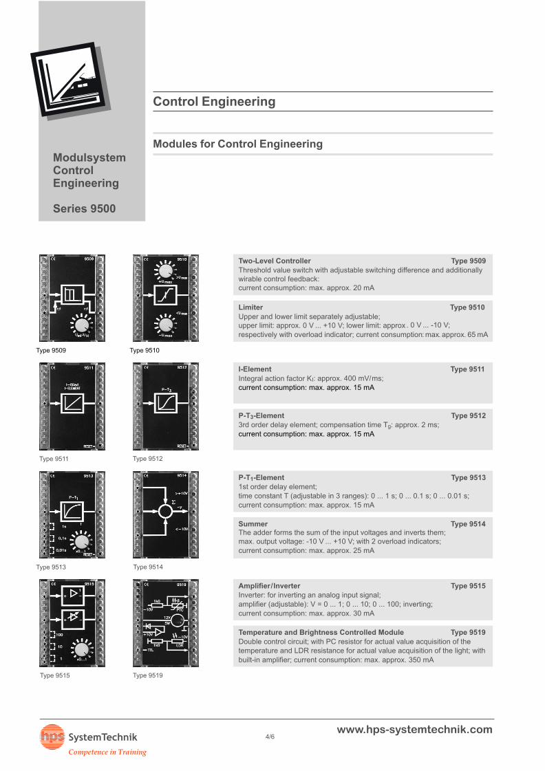
Amplifier/Inverter Type 9515Inverter: for inverting an analog input signal;amplifier (adjustable): V = 0 ... 1; 0 ... 10; 0 ... 100; inverting;
Type 9513
current consumption: max. approx. 30 mA
Temperature and Brightness Controlled Module Type 9519
Double control circuit; with PC resistor for actual value acquisition of thetemperature and LDR resistance for actual value acquisition of the light; with
built-in amplifier; current consumption: max. approx. 350 mA
Type 9514
Summer Type 9514The adder forms the sum of the input voltages and inverts them;max. output voltage: -10 V ... +10 V; with 2 overload indicators;current consumption: max. approx. 25 mA
P-T -Element Type 95131
1st order delay element;time constant T (adjustable in 3 ranges): 0 ... 1 s; 0 ... 0.1 s; 0 ... 0.01 s;current consumption: max. approx. 15 mA
Type 9511 Type 9512
I-Element Type 9511
: approx. 400 mV/ms;IIntegral action factor K
Type 9509
current consumption: max. approx. 15 mA
P-T -Element Type 95123
3rd order delay element; compensation time T : approx. 2 ms;g
Type 9510
current consumption: max. approx. 15 mA
Limiter Type 9510
Upper and lower limit separately adjustable;upper limit: approx. 0 V ... +10 V; lower limit: approx . 0 V ... -10 V;
respectively with overload indicator; current consumption: max. approx. 65 mA
Two-Level Controller Type 9509
Threshold value switch with adjustable switching difference and additionallywirable control feedback:current consumption: max. approx. 20 mA
Modules for Control Engineering
ModulsystemControlEngineering
Series 9500
www.hps-systemtechnik.com
Competence in Training
SystemTechnik 4/6
Control Engineering
Operating voltage supply for the Modules
+15 V DC/-15 V DC, by external power supply units.It is fed centrally through 2 mm or 4 mm jacks which areelectrically connected to the jacks of the individual locations.
Front panel
5 mm thick laminate, matt blue in colour, white printing
Plug-in locations
UNIVERSAL BOARD 1 (Type 8175): 12, with 4 jacks each-- UNIVERSAL BOARD 2 (Type 8176): 24, with 4 jacks each
Dimension/weight
UNIVERSAL BOARD 1 (Type 8175):-266 x 297 x 90 mm (w x h x d)/1.33 kg
- UNIVERSAL BOARD 2 (Type 8176):532 x 297 x 90 mm (w x h x d)/2.65 kg
With these two Boards,
UNIVERSAL BOARD 1 / UNIVERSAL BOARD 2
which differ in size only,
hps SystemTechnik offers a
low-cost introduction for con-
ducting experiments in con-
nection with the Modules for
Control Engineering.
The front panel of the Board
is divided into 12 or 24 slots.
The slots are used for plug-
ging in the modules and are
equipped with four 4 mm
jacks each.
The operating voltage is
also fed to the modules
through three of these jacks
(+15 V DC/-15 V DC/
ground).
The fourth jack is provided
for +5 V, e. g. for use of digi-
tal modules.
On the right and left hand
side of the Boards, 2 and
4 mm jacks are installed for
the external operating volt-
age supply.
To conduct the experiments,
the Boards can be placed at
an ergonomically favourable
angle on the table or sus-
pended in a demonstration
rack.
Technical Data
ModulsystemControlEngineering
Series 9500
www.hps-systemtechnik.com
Competence in Training
SystemTechnik 5/6
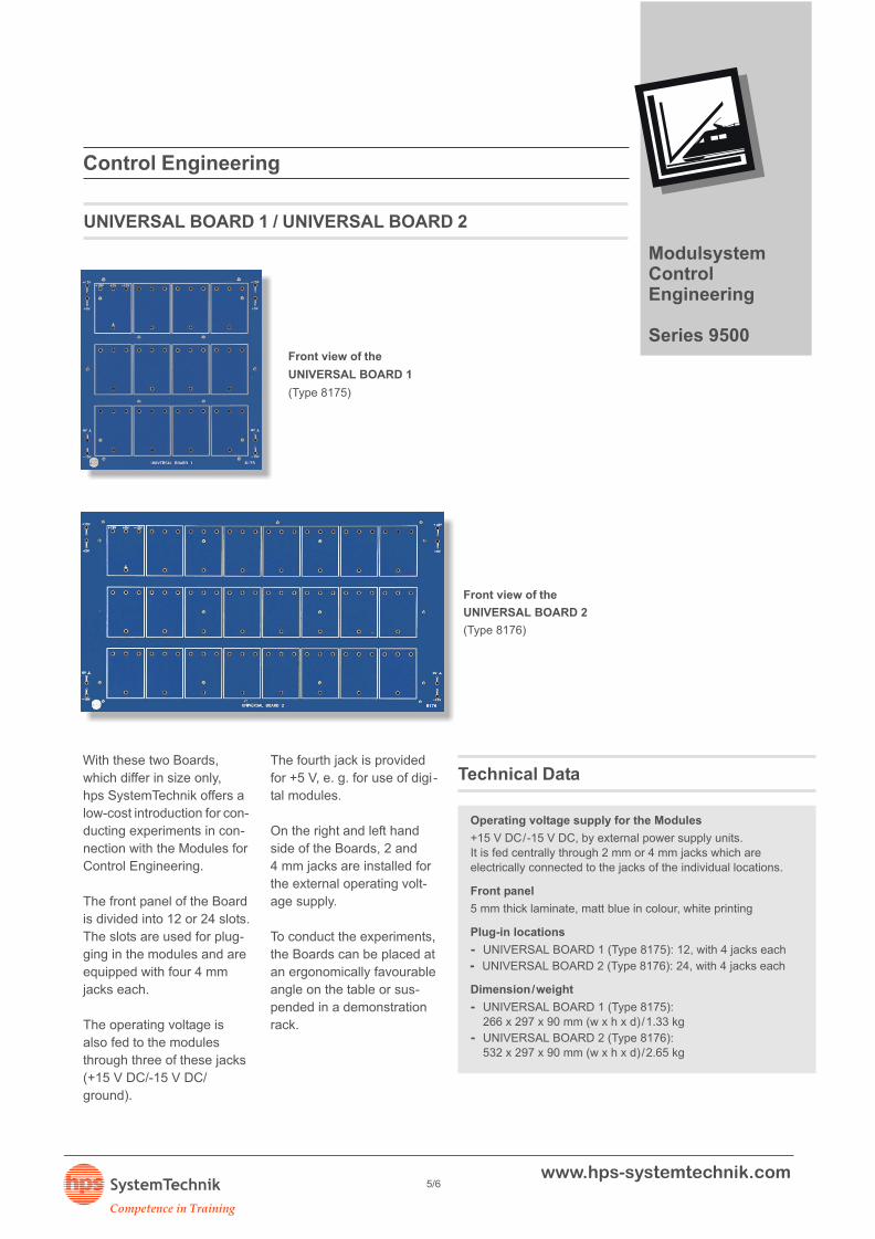
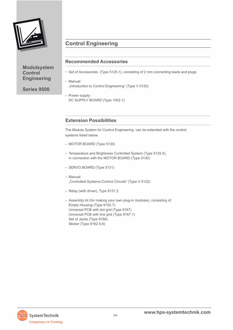
Front view of the
UNIVERSAL BOARD 2
(Type 8176)
Front view of the
UNIVERSAL BOARD 1
(Type 8175)
Control Engineering
Recommended Accessories
Set of Accessories (Type 5125.1), consisting of 2 mm connecting leads and plugs
-
-
Manual:
„Introduction to Control Engineering“ (Type V 0120)
- Power supply:
DC SUPPLY BOARD (Type 1002.1)
Extension Possibilities
The Module System for Control Engineering can be extended with the control
systems listed below.
- MOTOR BOARD (Type 5130)
- Temperature and Brightness Controlled System (Type 5125.5),
in connection with the MOTOR BOARD (Type 5130)
- SERVO BOARD (Type 5131)
- Manual:
„Controlled Systems/Control Circuits“ (Type V 0122)
- Relay (with driver), Type 9131.2
- Assembly kit (for making your own plug-in modules), consisting of:
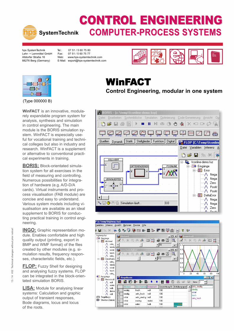
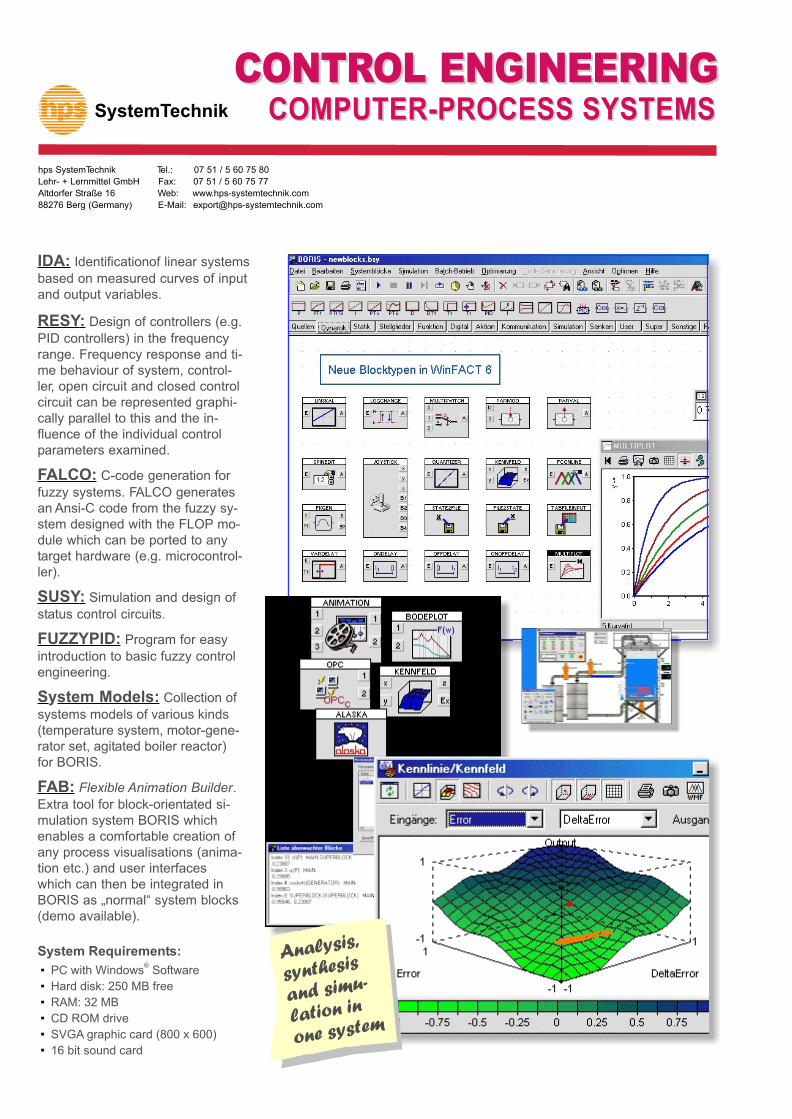
WinFACT is an innovative, modula-rely expandable program system foranalysis, synthesis and simulationin control engineering. The mainmodule is the BORIS simulation sy-stem. WinFACT is espescially use-ful for vocational training and techni-cal colleges but also in industry andresearch. WinFACT is a supplementor alternative to conventional practi-cal experiments in training.
BORIS: Block-orientated simula-
tion system for all exercises in thefield of measuring and controlling.Numerous possibilities for integra-tion of hardware (e.g. A/D-D/Acards). Virtual instruments and pro-cess visualisation (FAB module) areconcise and easy to understand.Various system models including vi-sualisation are available as an idealsupplement to BORIS for conduc-ting practical training in control engi-neering.
INGO: Graphic representation mo-
dule. Enables comfortable and highquality output (printing, export inBMP and WMF format) of the filescreated by other modules (e.g. si-mulation results, frequency respon-ses, characteristic fields, etc.).
FLOP: Fuzzy Shell for designing
and analysing fuzzy systems. FLOPcan be integrated in the block-orien-tated simulation BORIS.
LISA: Module for analysing linear
systems: Calculation and graphicoutput of transient responses,Bode diagrams, locus and locusof the roots.
WinFACTWinFACTControl Engineering, modular in one system
CONTRCONTROL ENGINEERINGOL ENGINEERINGCOMPUTER-PROCESS SYSTEMSCOMPUTER-PROCESS SYSTEMS
SystemTechnik
CONTRCONTROL ENGINEERINGOL ENGINEERINGCOMPUTER-PROCESS SYSTEMSCOMPUTER-PROCESS SYSTEMS
hps SystemTechnik Tel.: 07 51 / 5 60 75 80
Lehr- + Lernmittel GmbH Fax: 07 51 / 5 60 75 77
Altdorfer Straße 16 Web: www.hps-systemtechnik.com
PID controllers) in the frequencyrange. Frequency response and ti-me behaviour of system, control-ler, open circuit and closed controlcircuit can be represented graphi-cally parallel to this and the in-fluence of the individual controlparameters examined.
FALCO: C-code generation for
fuzzy systems. FALCO generatesan Ansi-C code from the fuzzy sy-stem designed with the FLOP mo-dule which can be ported to anytarget hardware (e.g. microcontrol-ler).
SUSY: Simulation and design of
status control circuits.
FUZZYPID: Program for easy
introduction to basic fuzzy controlengineering.
System Models: Collection of
systems models of various kinds(temperature system, motor-gene-rator set, agitated boiler reactor)for BORIS.
FAB: Flexible Animation Builder.
Extra tool for block-orientated si-mulation system BORIS whichenables a comfortable creation ofany process visualisations (anima-tion etc.) and user interfaceswhich can then be integrated inBORIS as „normal“ system blocks(demo available).
·
·
System Requirements:®
PC with Windows Software
Hard disk: 250 MB free
RAM: 32 MB
CD ROM drive
SVGA graphic card (800 x 600)
16 bit sound card
IDA: Identificationof linear systems
based on measured curves of inputand output variables.
Analysis,
synthesis
and simu-n
lation i
one system
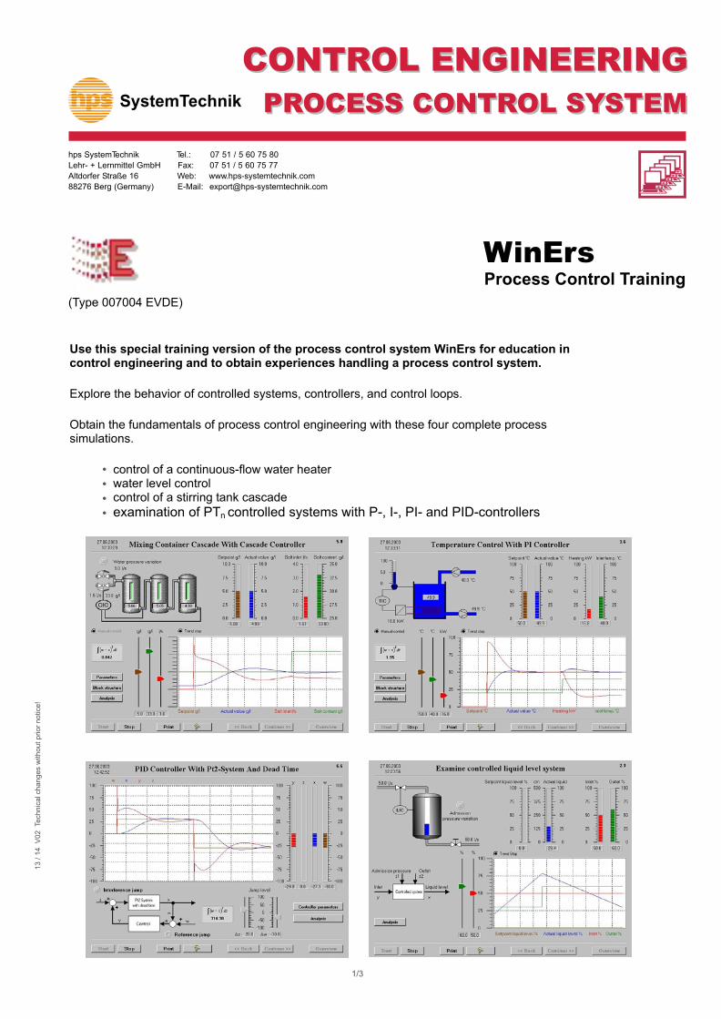
Use this special training version of the process control system WinErs for education in control engineering and to obtain experiences handling a process control system.
Explore the behavior of controlled systems, controllers, and control loops.
Obtain the fundamentals of process control engineering with these four complete process simulations.
control of a continuous-flow water heater water level control control of a stirring tank cascade examination of PTn controlled systems with P-, I-, PI- and PID-controllers
SystemTechnik
hps SystemTechnik Tel.: 07 51 / 5 60 75 80
Lehr- + Lernmittel GmbH Fax: 07 51 / 5 60 75 77
Altdorfer Straße 16 Web: www.hps-systemtechnik.com
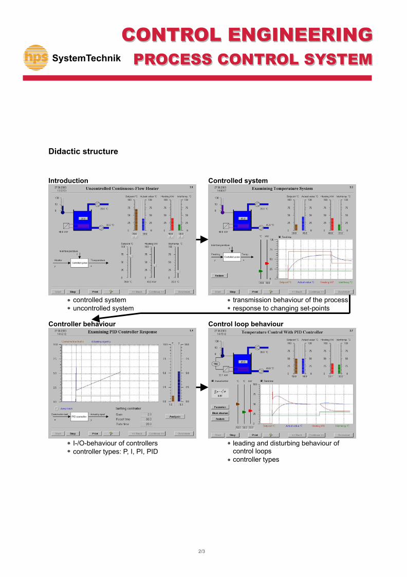
I-/O-behaviour of controllers controller types: P, I, PI, PID
Controlled system
transmission behaviour of the process response to changing set-points
Control loop behaviour
leading and disturbing behaviour of control loops controller types
SystemTechnik
CONTROL ENGINEERING
PROCESS CONTROL SYSTEM
2/3
Measurement and data acquisition
Controller parameters
Block strukture
Bar graphs for signal representation
Online trend chart
SystemTechnik
CONTROL ENGINEERING
PROCESS CONTROL SYSTEM
3/3
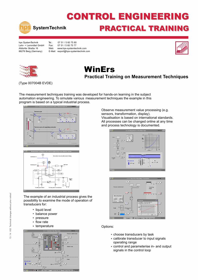
The measurement techniques training was developed for hands-on learning in the subject automation engineering. To simulate various measurement techniques the example in this program is based on a typical industrial process.
The example of an industrial process gives the possibility to examine the mode of operation of transducers for:
liquid level balance power pressure flow rate temperature
Observe measurement value processing (e.g. sensors, transformation, display). Visualisation is based on international standards. All processes can be changed online at any time and process technology is documented.
Options:
choose transducers by task
SystemTechnik
hps SystemTechnik Tel.: 07 51 / 5 60 75 80
Lehr- + Lernmittel GmbH Fax: 07 51 / 5 60 75 77
Altdorfer Straße 16 Web: www.hps-systemtechnik.com
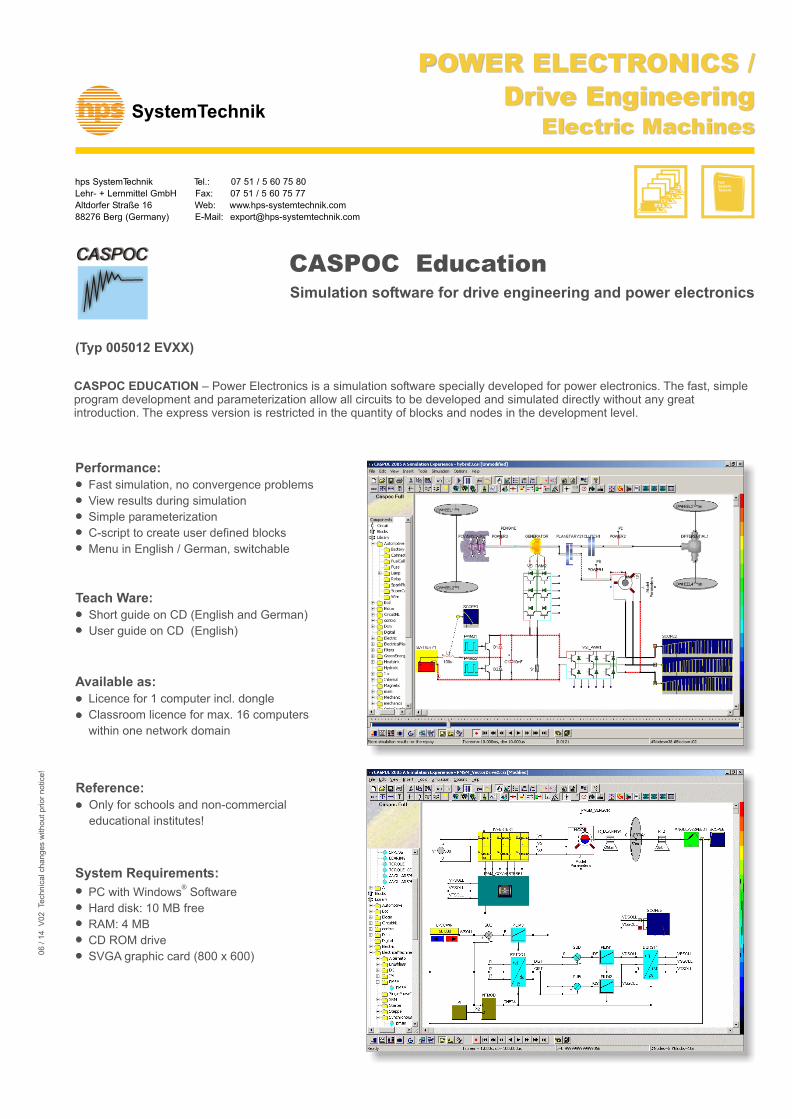
CASPOC EDUCATION – Power Electronics is a simulation software specially developed for power electronics. The fast, simple program development and parameterization allow all circuits to be developed and simulated directly without any great introduction. The express version is restricted in the quantity of blocks and nodes in the development level.
Simulation software for drive engineering and power electronics
Performance: Fast simulation, no convergence problems
View results during simulation
Simple parameterization
C-script to create user defined blocks
Menu in English / German, switchable
Teach Ware: Short guide on CD (English and German)