where Vq, Vd, Iq, Id, Ag, and Ad are q-axis and d-axis components of voltage, current and flux linkage
respectively. er is the rotor angle. At steady state, equ. (3) will yield to (4), which can be
used as feed forward equations.
Vq = Rsfq + weLdId
+ Et
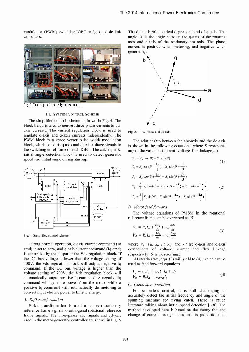
Vd = Rsfd - weLqIq C. Catch-spin operation
(4)
For sensorless control, it is still challenging to accurately detect the initial frequency and angle of the
spinning machine for flying catch. There is much literature talking about initial speed detection [6-8]. The
method developed here is based on the theory that the
change of current through inductance is proportional to
The 2014 International Power Electronics Conference
the applied voltage and time, and inversely proportional to the inductance.
The typical schematic of the 2-level PWM output and
the motor/grid is shown in Fig. 6, where switches Sl-S6
are power switching devices. The line inductances Ll-L3
are used to reduce current harmonics and are optional.
S1 +
S2
Fig. 6. Typical schematic of the 2-level PWM output and the motor/grid.
Assuming the motor has the three-phase open circuit
voltage as shown below:
Va = Vm cosCwt + e) Vb = Vm COS ( wt + e _
Z;) (5)
Vc = Vm COS ( wt + e + Z;)
If the bottom three switches (S2, S4 and S6) close for a
period of time L1t, the final current flow through phase a,
b, and c will be
M I a = - Vm cosCwt + e) Ls M ( ZIT) Ib = - Vm COS wt + e - --Ls 3 M ( ZIT) Ie = - Vm cos wt + e + --Ls 3
From (6), at time t=O, we have,
1': = J2 + (Ib-1d2
m a 3
fJ = tan-1 CJi2)
(6)
(7)
The frequency (OJ) can be easily calculated from Vm based on the known back EMF constant.
After initial estimation, further refining of the speed
and angle is required to accurately estimate the speed and
angle.
D. Flux Estimation and PLL Flux estimation is the key part of sensorless motor
control. The performance of flux estimation directly
affects the system performance of the motor control.
Virtual flux estimation together with phase lock loop
(PLL) is used to provide reliable position and speed estimation. The virtual flux estimator uses q and d axes
components of voltage command and current feedback to estimate the position and speed. By using PLL, the flux
can be tracked smoothly, thus the position noise due to
arc-tangent function is greatly reduced.
1839
IV. SIMULATION
The control scheme has been verified using
Matlab/Simulink simulations. Fig. 7 shows the simulation
model.
Fig. 7. Simulation model.
Fig. 8 and Fig. 9 show the simulated dc bus voltage
response and phase current waveforms when a step load
of 0% to 100% applied at the time of 0 seconds. The results show that the dc bus voltage dip is below 5%.
705
700
695
690
;;-� 685
680
675
670
665 -0.01
DC bus voltage \IS time
�
1\ I \ / \ / \ V \ / \ / �
0.01 0.02 0.03 0 04 0.05 0 00 Time(seconds)
Fig. 8. DC bus voltage overshoot when step load from 0 kW to 750 kW at 10,000 rpm.
Fig. 9. Phase current waveforms when step load from 0 kW to 750 kW at 10,000 rpm.
-0.01 0 0.01 0.02 0.03 0.04 0.05 0.06-2000
-1500
-1000
-500
0
500
1000
1500
2000
Time(seconds)
Idc(
A)
Phase current vs.time
IaIbIc
The 2014 International Power Electronics Conference
Fig. 10 and Fig. 11 show the dc bus voltage response and phase current waveforms when a step load of 100 % to 0% is applied at the time of 0 seconds. The result also
shows that the dc bus voltage overshoot is below 5%.
735
730
725
720
> :g- 715 >
710
705
700
695 -0.01
DC bus voltage vs time
11\ \
I \ I 1\ I \ / \
J \ "'--
0,01 0.02 0.03 Time(seconds)
0.04 0.05 0 06
Fig. 10. DC bus voltage overshoot when step load from 750 kW to 0 kWat 10,000 rpm.
Phase current \IS,time 2000,---�----�----,---�----�----,-==�
1500
1000
500
;;C �
-500
-1000
-1500
0.04 0.05 0.06 Time(seconds)
Fig. I I. Phase current waveforms when step load from 750 kW to 0 kW at 10,000 rpm.
V. TEST RESULTS
Catch-spin performance was tested at different initial
speed conditions (shown in Table II). From these results we can see that the speed error is less than 5%. The
detected speed error is lower at higher speeds because of
the higher current signal to noise ratio at higher speeds.
Fig. 12 shows the phase current waveform when catch
spinning and then boosting the dc bus voltage to the rated voltage of 700V.
Fig. 12. Current waveform when catch -spinning and then boosting dc bus voltage to the rated 700V.
The DC bus voltage variations under transient load
conditions were tested at 580 kW load condition and
compared with simulated results. Fig. 13 to Fig. 15 show
simulation results and actual test results of the step load response of the dc bus voltage and phase current when
the external load changes from 0 kW to 580 kW. The
results show that the simulation and actual test results
match very well.
2000
1500
1000
A .U'I�""A o ��
" ,
-100 0
-150 0
-200 0 0.005
Generator current '.6 time
0,01 0.015 Time(sec)
0.02 0,025 0,03
Fig. 13. Measured phase current when the load changed from 0 to 580 kWat 10,000 rpm.
1500
1000
:i 500 c � a ill j!1 D.. -500
-1000
-1500
Simulated phase current vs. time
A �A
.� �
'� � v�� 0.005 0.01 0.015
Time(seconds)
-- Phasea -- Phaseb -- Phase c
0.02 0.025
Fig. 14. Simulated phase current when load changes from 0 to 580 kW at 10,000 rpm.
The 2014 International Power Electronics Conference
705
700
695
� 690 '" Ol 2 � 685 "l
.0 u 680 o
675
670
665 -0.02 -0.01 o
DC bus voltage vs. time
.1.,1.1,1. �II' "WII""'''''''' ' rr'I�" IU' I -- Measured, �
,J 1-- Simulation
I \ 1/ �
v
�m �m 0.00 O.� �� �OO Time(sec)
Fig. 15. DC bus voltage dip when step load from 0 to 580kW at 10,000 rpm.
Fig. 16 shows the measured and simulated dc voltage
waveforms when the 580 kW load is removed at time O.
Fig. 15 and Fig. 16 show that transient response of the dc bus voltage is less than 5%.
735
730
725
� 720 " �
� 715
� () o 710
705
700 ..
If • ..., "� r"'I"fl'"' 695
-0.02 -0.01
DC bus voltage vs time
II � 'I \
\ \
l
1\ \ \ .. �
0.01 0.02 Time(sec)
0.03
1-- Measurement -- Sirrulalion
0.04 0.05 0.06
Fig. 16. DC bus voltage overshoot when step load from 580kW to 0 kW at 8,000 rpm.
VI. CONCLUSION
The control of a 750kW permanent magnet
synchronous generator which is used for marine hybrid
turbocharger applications has been proposed to meet the
tough requirement of less than 5% dc bus voltage variation under transient load condition. The system overview, control methodology, and control simulation
using Matlab/Simulink has been conducted to provide simulation results that meet system performance
requirements. Comparison of the tests and simulation
results show the validation of the simulation model and the promising performance of the generator control and dc bus voltage regulation, meeting the performance
requirements of the system.
1841
REFERENCES
[I] B. Bae, S. Sui, 1. Kwon, and J. Byeon, "Implementation of Sensorless Vector Control for Super-High-Speed PMSM of Turbo-Compressor," IEEE Trans. on Industry Applications, vol. 39, no. 3, pp. 811-818, 2003.
[2] 1. X. Shen, Z. Q. Zhu, and D. Howe, "Improved Speed Estimation in Sensorless PM Brushless AC Drives," IEEE Trans. on Industry
Applications, vol. 38, no. 4, pp. 1072-1080, 2002. [3] I. , S. Tomita, M. Doki, S. Okuma, S. "Sensorless Control of
Permanent-Magnet Synchronous Motors Using Online Parameter Identification Based on System Identification Theory" IEEE
Trans. Ind. Applications, 2006, vo1.53, no.2, pp.363-372, 2006. [4] 1. H. Kim, S. Lee, R. Y. Kim, and D. S. Hyun, "A Sensorless
Control using Extended Kalman Filter For an Interior Permanent Magnet Synchronous Motor Based on an Extended Rotor Flux," IEEE 38th Annual Con] on Industrial Electronics Society, Oct. 2012.
[5] Chee-mun Ong, Dynamic Simulation of Electric Machinery Using MatlablSimulink, Prince Hall PTR, 1997.
[6] M. Tursini, R. Petrella, and F. Parasiliti, "Initial Rotor Position Estimation Method for PM Motors," IEEE Trans. Ind. Applications, vo1.39, no.6, pp.1630-1640, 2003.
[7] P. B. Schmidt, M. L. Gasperi, G. Ray, and A. H. Wijenayake, "Initial rotor angle detection of nonsalient pole permanent magnet synchronous machine," IEEE-lAS Annual Meeting, pp. 459-463, New Orleans, 1997.
[8] T. Noguchi, K. Yamada, S. Kondo, and I. Takahashi, "Initial Rotor Position Estimation Method of Sensorless PM Synchronous Motor with No Sensitivity to Armature Resistance," IEEE Trans. on Industry Electronics, vol. 45, no.l, pp. 118-125, 1998.