2 Control of a DSTATCOM Coupled with a Flywheel Energy Storage System to Improve the Power Quality of a Wind Power System Gastón Orlando Suvire and Pedro Enrique Mercado Instituto de Energía Eléctrica – Universidad Nacional de San Juan Argentina 1. Introduction Wind power generation is considered the most economic viable alternative within the portfolio of renewable energy resources. Among its main advantages are the large number of potential sites for plant installation and a rapidly evolving technology. However, the lack of controllability over the wind and the type of generation system used cause problems to the electric systems. Among such problems are those produced by wind power short-term fluctuations, e.g., in the power quality and in the dynamics of the system (Slootweg & Kling, 2003; Ackermann, 2005; Suvire & Mercado, 2008; Chen & Spooner, 2001; Mohod & Aware; 2008; Smith et al., 2007). In addition, the reduced cost of power electronic devices as well as the breakthrough of new technologies in the field of electric energy storage makes it possible to incorporate this storage with electronic control into power systems (Brad & McDowall, 2005; Carrasco, 2006; Barton & Infield, 2004; Hebner et al., 2002). These devices allow a dynamic control to be made of both voltage and flows of active and reactive power. Therefore, they offer a great potential in their use to mitigate problems introduced by wind generation. Based on the results obtained by analyzing different selection criteria, a Distribution Static Synchronous Compensator (DSTATCOM) coupled with a Flywheel Energy Storage System (FESS) has been proposed as the most appropriate system for contributing to the smoothing of wind power short-term fluctuations (Suvire & Mercado, 2007). A DSTATCOM is a fast- response, solid-state power controller that provides flexible voltage control at the point of connection to the utility distribution feeder for power quality improvements (Song & Johns, 1999). This device can exchange both active and reactive power if an energy storage system is included into the DC bus. FESSs store kinetic energy in a rotating mass, and they have been used as short-term energy storage devices. FESSs can be classified as low-speed flywheel (LS-FESS) and high-speed flywheel (HS-FESS). HS-FESSs are a newer technology and they provide better speeds of response, cycling characteristics and electric efficiencies than LS-FESS (Hebner et al., 2002; Andrade et al., 2007). All these characteristics enable the HS-FESS (FESS from now on), working with a DSTATCOM device, to mitigate voltage fluctuations and to correct power fluctuations of a wind power system. With these aspects in mind, it turns necessary to ponder the information stemming from models that simulate the dynamic interaction between the DSTATCOM/FESS device and power systems with wind www.intechopen.com
Transcript
2
Control of a DSTATCOM Coupled with a Flywheel Energy Storage System to Improve the
Power Quality of a Wind Power System
Gastón Orlando Suvire and Pedro Enrique Mercado Instituto de Energía Eléctrica – Universidad Nacional de San Juan
Argentina
1. Introduction
Wind power generation is considered the most economic viable alternative within the portfolio of renewable energy resources. Among its main advantages are the large number of potential sites for plant installation and a rapidly evolving technology. However, the lack of controllability over the wind and the type of generation system used cause problems to the electric systems. Among such problems are those produced by wind power short-term fluctuations, e.g., in the power quality and in the dynamics of the system (Slootweg & Kling, 2003; Ackermann, 2005; Suvire & Mercado, 2008; Chen & Spooner, 2001; Mohod & Aware; 2008; Smith et al., 2007). In addition, the reduced cost of power electronic devices as well as the breakthrough of new technologies in the field of electric energy storage makes it possible to incorporate this storage with electronic control into power systems (Brad & McDowall, 2005; Carrasco, 2006; Barton & Infield, 2004; Hebner et al., 2002). These devices allow a dynamic control to be made of both voltage and flows of active and reactive power. Therefore, they offer a great potential in their use to mitigate problems introduced by wind generation. Based on the results obtained by analyzing different selection criteria, a Distribution Static Synchronous Compensator (DSTATCOM) coupled with a Flywheel Energy Storage System (FESS) has been proposed as the most appropriate system for contributing to the smoothing of wind power short-term fluctuations (Suvire & Mercado, 2007). A DSTATCOM is a fast-response, solid-state power controller that provides flexible voltage control at the point of connection to the utility distribution feeder for power quality improvements (Song & Johns, 1999). This device can exchange both active and reactive power if an energy storage system is included into the DC bus. FESSs store kinetic energy in a rotating mass, and they have been used as short-term energy storage devices. FESSs can be classified as low-speed flywheel (LS-FESS) and high-speed flywheel (HS-FESS). HS-FESSs are a newer technology and they provide better speeds of response, cycling characteristics and electric efficiencies than LS-FESS (Hebner et al., 2002; Andrade et al., 2007). All these characteristics enable the HS-FESS (FESS from now on), working with a DSTATCOM device, to mitigate voltage fluctuations and to correct power fluctuations of a wind power system. With these aspects in mind, it turns necessary to ponder the information stemming from models that simulate the dynamic interaction between the DSTATCOM/FESS device and power systems with wind
www.intechopen.com
Energy Storage
20
generation. Such models allow performing the necessary preliminary studies before connecting the DSTATCOM/FESS to the grid. Many solutions are proposed and studied in the literature to compensate wind power fluctuations using a flywheel energy storage device (Boutot et al., 2002; Takahashi et al., 2005; Cimuca et al., 2004; Cárdenas et al., 2004). These solutions have been proposed mainly using LS-FESS and with simplified models of the device. The complete control to interact with wind power generation is not explained in detail in the analyzed literature. The aim of this paper is to present a detailed model and a multi-level control of a DSTATCOM controller coupled with FESS to improve the integration of wind generators (WGs) into a power system. A model of a DSTATCOM/FESS device is proposed with all its components represented in detail. Moreover, the complete control for this device is suggested. This control implements a new approach based on multi-level control technique. To mitigate wind power fluctuations, the control includes three modes of operation of the DSTATCOM/FESS device, namely, voltage control, power factor correction, and active power control. Validation of models and control schemes is carried out through simulations by using SimPowerSystems of SIMULINK/MATLAB™.
2. Modelling of the DSTATCOM/FESS
In order to study the dynamic performance of the DSTATCOM/FESS controller, a model of the combined system is proposed that is depicted in Fig. 1. This model consists mainly of the DSTATCOM controller, the Interface converter and the FESS device.
Ud C
S1-1 S1-3 S1-5
S1-4 S1-6 S1-2
S2-1 S2-3 S2-5
S2-4 S2-6 S2-2
+
-
AC Bus
DC Bus
Coupling
Line Filter
Cfa Cfb Cfc
Two-level VSI
PMSMFlywheel
DSTATCOM
Two-level VSI
INTERFACE
FESS
IGBT Diode
Transformer
PCC
Fig. 1. Representation of the DSTATCOM/FESS controller
The DSTATCOM and the Interface use two-level VSIs. The commutation valves used are Insulated Gate Bipolar Transistors (IGBT) with anti-parallel diodes. The VSIs are modeled with detailed blocks of the switches and diodes, incorporated into the simulation program. The technique of sinusoidal pulse width modulation (SPWM) is used to obtain a sinusoidal voltage waveform. In order to reduce the disturbance produced on the distribution system by the high-frequency switching harmonics generated by the SPWM control, a low pass sine wave filter is used. The energy stored by a FESS is calculated by using (1).
( )2 2max min
1
2E J ω ωΔ = − (1)
www.intechopen.com
Control of a DSTATCOM Coupled with a Flywheel Energy Storage System to Improve the Power Quality of a Wind Power System
21
where ΔE is the energy stored by the flywheel, ┱max and ┱min are, respectively, the maximum and minimum operation speed of the flywheel, and J is the moment of inertia of the flywheel. The exchange of power between the flywheel and the Interface is made by using a Permanent Magnet Synchronous Machine (PMSM). The PMSM is modeled with a detailed block included in the simulation program and with parameters obtained from the manufacturer data sheets (Beacon Power, 2009; Flywheel Energy Systems, 2009; Urenco Power Technologies, 2009). The flywheel is modeled as an additional mass coupled to the rotor shaft of the PMSM (Samineni et al., 2006).
3. DSTATCOM/FESS control
The control proposed for the DSTATCOM/FESS device is divided into two parts, the DSTATCOM control and the FESS control. For each part, a multi-level control scheme is suggested. This scheme has its own control objectives for each level. In this way, a system of complex control is divided into several control levels, which are simpler to design (Xie et al., 2002; Molina & Mercado, 2004). Both parts of the multi-level control scheme, i.e., the DSTATCOM and the FESS, are divided into three quite distinct levels: external, middle and internal level, shown in simplified way in Fig. 2.
Reference Values
Electric
Grid
Measured Variables
FESS-VSI DSTATCOM-VSI Coupling
TransformerPMSM
Flywheel
FESS Control
Ext. Level
Mid. Level
Int. Level
Measured Variables
Measured Variables
IGBTsControl Pulses
Expected Output
Reference Values
Ext. Level
Mid. Level
Int. Level
Expected Output
IGBTsControl Pulses
DSTATCOM Control
PCC
Fig. 2. Structure of the multi-level control of the DSTATCOM/FESS
3.1 DSTATCOM control Each control level of the DSTATCOM has certain functions. The external level is responsible for determining the active and reactive power exchange between the DSTATCOM and the utility system. The middle level control allows the expected output to dynamically track the
www.intechopen.com
Energy Storage
22
reference values set by the external level. The internal level is responsible for generating the switching signals for the valves of the VSI of the DSTATCOM. The control algorithm of the DSTATCOM with all its parts in detail is shown in Fig. 3. Control is performed with the synchronous-rotating dq reference frame. The coordinate system is defined with the d-axis always coincident with the instantaneous voltage vector (ud = |u|, uq = 0). Consequently, the d-axis current component contributes to the instantaneous active power and the q-axis current component represents the instantaneous reactive power.
Ku
i*Qr
ud
Ur iQr
i*Qr
ud
Kq1
a
b
S
i*Pr
ud
KpPreg
iPr
PI
Coordinate
Transformation
abc dq
Coordinate
Transformation
abc dq
ua ub uc ia ib ic
θsiq
id
ud
+- +
+
iqr uinv_qΔiqr
++
-++
idr Δidr -
ωLt
ωLt
iq
id
ud
+-
UdrΔUd
Ud
x2
x1
uinv_d
2/3
2/3
θs
Coordinate
Transformation
dq abc
Phase
Locked
Loop
Carriers
Generator
1
0
uabc_r
-1
VSI Pulses
Generator
IGBTs
Control
Pulses
ua ub ucExternal Level Control Middle Level Control Internal Level Control
Current Regulator
DC Voltage Regulator
ftri
PI
PI
PI
PI
PI+-
Rq
Qr
+-
+-
+-Pge
Pr
Qge
0
Fig. 3. Multi-level control scheme of the DSTATCOM device
External level control The external level control scheme proposed (left side in Fig. 3) is designed for performing three major control objectives, namely, the voltage control mode (VCM), which is activated when switch S is in position a, the power factor control mode (PFCM), activated in position b, and the active power control mode (APCM), which is always activated. The VCM consists in controlling the voltage at the PCC (Point of Common Coupling) of the DSTATCOM through the modulation of the reactive component of the output current. To this aim, the instantaneous voltage at the PCC (ud) is computed by using a synchronous-rotating orthogonal reference frame and is then compared with a reference voltage (Ur). A voltage regulation droop (or slope) Rq is included in order to allow the terminal voltage of the DSTATCOM to vary in proportion with the compensating reactive current. In the PFCM, the reactive power reference (Qr) is set to the measured value of the reactive power of wind generation (Qge). In this way, all the reactive power required by the WG is provided and thus the WG-DSTATCOM/FESS system is able to maintain the unity power factor. A standard PI compensator is included to eliminate the steady-state error in the reactive current reference computation. The APCM allows controlling the active power exchanged with the electric system. The computation of the reference active power (Pr) depends on the active power value injected by the wind generation. This value is the difference between the regulation power desirable (Preg) and the active power measured from the WG (Pge). The Preg is the active power that needs to be delivered to the electric system by the WG-DSTATCOM/FESS system. A standard PI compensator is also included to eliminate the steady-state error in the active current reference computation.
www.intechopen.com
Control of a DSTATCOM Coupled with a Flywheel Energy Storage System to Improve the Power Quality of a Wind Power System
23
Middle level control This block has two main parts, the DC voltage regulator and the current regulator. A functional simplified scheme of this control level is shown in the central part of Fig. 3. The dynamic equations governing the power instantaneous transfer between the DSTATCOM and the electrical network are given by (2).
where Rt and Lt are, respectively, the resistance and equivalent leakage inductance of the coupling transformer of the DSTATCOM. A control methodology to obtain a decoupled control of the current components, id and iq, is derived from (2). To achieve this objective, two appropriate control signals x1 and x2 are introduced. If iqRt/Lt = x1 and idRt/Lt = x2, and (2) is worked and these variables introduced; then (2) results in (3).
As can be noticed from the equation above, id and iq respectively respond to x1 and x2 with no cross-coupling. Conventional PI controllers with proper feedback from the DSTATCOM/FESS output current component are used to obtain the decoupling condition. In addition, the AC and DC sides of the DSTATCOM are related by the power balance between the input and the output as described by (4).
( ) 2
_ _
3
2d d
AC inv d d inv q q d DCpd
dU UP u i u i CU P
dt R= + = − − = (4)
where Rpd is the loss resistance of the VSI and Ud is the DC voltage. Considering uinv_d = kinvcosαUd and uinv_q = kinvsinαUd, with kinv = maat/2, (ma modulation index, at = n1/n2: voltage ratio of the coupling transformer) and α is the phase-shift between the converter output voltage and the grid AC voltage; (4) may be rewritten as:
3 1 3 1
cos sin2 2
d dinv d inv q
pd
dU Uk i k i
dt C C CRα α= − − − (5)
Another PI compensator which allows eliminating the steady-state voltage variations at the DC bus is used by forcing a small active power exchange with the electric grid.
Internal level control A basic scheme of the internal level control of the DSTATCOM is shown on the right side of Fig. 3. This level is mainly composed of a line synchronization module and a three-phase PWM firing pulses generator for the DSTATCOM VSI. The line synchronization module consists mainly of a phase locked loop (PLL) (Bose, 2002). The three-phase firing pulses generator produces both a frequency triangular wave (ftri) and the firing pulses for each IGBT of the VSI by comparing this triangular wave with the desired reference three-phase voltage, uabc_r.
www.intechopen.com
Energy Storage
24
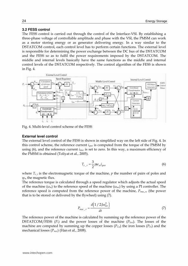
3.2 FESS control The FESS control is carried out through the control of the Interface-VSI. By establishing a three-phase voltage of controllable amplitude and phase with the VSI, the PMSM can work as a motor storing energy or as generator delivering energy. In a way similar to the DSTATCOM control, each control level has to perform certain functions. The external level is responsible for determining the power exchange between the DC bus of the DSTATCOM and the FESS so as to fulfil the power requirements imposed by the DSTATCOM. The middle and internal levels basically have the same functions as the middle and internal control levels of the DSTATCOM respectively. The control algorithm of the FESS is shown in Fig. 4.
Fig. 4. Multi-level control scheme of the FESS
External level control The external level control of the FESS is shown in simplified way on the left side of Fig. 4. In this control scheme, the reference current iqmr is computed from the torque of the PMSM by using (6), and the reference current idmr is set to zero. In this way, a maximum efficiency of the PMSM is obtained (Toliyat et al., 2005).
_
3
2e r m qmrT p iψ= (6)
where Te_r is the electromagnetic torque of the machine, p the number of pairs of poles and ┰m the magnetic flux. The reference torque is calculated through a speed regulator which adjusts the actual speed of the machine (┱m) to the reference speed of the machine (┱mr) by using a PI controller. The reference speed is computed from the reference power of the machine, Pmac_r, (the power that is to be stored or delivered by the flywheel) using (7).
( )2
_
1 / 2 mrmac r
d JP
dt
ω= (7)
The reference power of the machine is calculated by summing up the reference power of the DSTATCOM/FESS (Pr) and the power losses of the machine (Ploss). The losses of the machine are computed by summing up the copper losses (PCu) the iron losses (PFe) and the mechanical losses (Pmec) (Han et al., 2008).
www.intechopen.com
Control of a DSTATCOM Coupled with a Flywheel Energy Storage System to Improve the Power Quality of a Wind Power System
25
Middle level control A functional simplified scheme of middle level control is shown in the central part of Fig. 4. This level is basically composed of a current regulator. The control is made by using vector control; the main characteristic of this control is the synchronization of the stator flux with the rotor. The currents in the d and q axes are regulated separately. The control scheme is similar to the middle level control of the DSTATCOM, except that the synchronism angle to make the coordinate transformation, θs, is computed in a different way. In this case, the angle is obtained by measuring the position angle of the machine (θm) and multiplying by the number of pairs of poles.
Internal level control A basic scheme of the internal level control of the FESS is shown on the right side of Fig. 4. This control level is quite similar to that of the internal level control of the DSTATCOM except that it does not have the phase locked loop block due to the fact that the angle θs is obtained through measurement as mentioned before.
4. Test system
The test power system used to study the dynamic performance of the DSTATCOM/FESS device proposed is shown in Fig. 5 as a single line diagram. This sub-transmission system operates at 13.8 kV/50Hz and implements a dynamically modeled wind generator linked to a bulk power system represented by an infinite bus type. The WG (rated power: 750 kW) uses an induction generator with a squirrel-cage rotor and is connected to the grid through a transformer with star-triangle winding. The demand for reactive power from the WG is supplied by capacitors so as to reach a close-to-one power factor. The WG is modeled with blocks of an induction generator and a wind turbine available in the library of the simulation program and with parameters taken from the manufacturer data sheets (Neg Micon, 2009; Ecotècnia, 2009). The sub-transmission line is modeled by using lumped parameters. All loads are modeled by constant impedances and are grouped at bus 4 (Ld1: 0.3 MW and Ld2: 0.7 MW). The DSTATCOM/FESS device proposed (maximum rated power: 100 kW and rated storage capacity: 750 Wh) is connected to the main bus (bus 3) through Bk 4. The DC voltage of the DSTATCOM is 750 V and the capacitor used has a rated capacitance of 1000 μF. The
Infinite BusZ Thevenin
Bus 1 Bus 2 Bus 3 Bk 1
Bus 5 Bus 6 Bus 7
30 km
Bk 3 Bk 4DSTATCOM/
FESS
0.3 MW
Cap.
WGT1 0.69/
13.8 kV
13.8 kV
0.7 MW
Bk 2
Bus 4
Ld1
Ld2
PCC
Fig. 5. Test power system
www.intechopen.com
Energy Storage
26
DSTATCOM-VSI works with a switching frequency of 8 kHz whereas the Interface-VSI works with 20 kHz. The parameters of the FESS (PMSM and flywheel) are obtained from the manufacturer data sheets (Beacon Power, 2009; Flywheel Energy Systems, 2009; Urenco Power Technologies, 2009). The major test system data are summarized in Appendix A while the DSTATCOM/FESS data are in Appendix B. The analysis and validation of the models and control algorithms proposed for the DSTATCOM/FESS controller are carried out through simple events that impose high demands upon the dynamic response of the device. A test is made of the device proposed in the test system shown in Fig. 5. For this, a variation profile of wind speed is applied to the WG so that it makes the DSTATCOM/FESS work in both ways, by storing and delivering energy. In addition, external perturbations are imposed, like a load variation, and the behaviour of the device in the different control modes is observed.
5. Simulation results
The basic system shown in Fig. 5 is used. A suitable profile for variation of the wind speed is applied, as shown in Fig. 6.
0.5 1 1.5 2 2.5 3 3.5 4 4.5 5 5.5 66
7
8
9
10
11
12
Time (s)
Win
d s
peed (
m/s
)
Fig. 6. Wind speed
The wind speed variations cause significant fluctuations in the active and reactive power injected by the WG. The capacitor bank used with the WG is adjusted to compensate for the reactive power when the WG operates at a mean wind speed of 10 m/s. In bus 4, the load Ld1 = 0.3 MW is first connected (in t = 0 s) and then, in t = 3 s, the load Ld2 = 0.7 MW is added. The behaviour of the system is analyzed in both cases, when the DSTATCOM/FESS is disconnected (Bk 4 opened) and connected (Bk 4 closed). The variations of active power injected by the WG-DSTATCOM/FESS system for both cases are shown in Fig. 7. With the DSTATCOM/FESS device connected, the variations of power from the WG are reduced and an active power that is practically constant is injected to the system. For the reactive power control, three different cases are presented: DSTATCOM/FESS disconnected, DSTATCOM/FESS connected working in Power Factor Control Mode (PFCM); and DSTATCOM/FESS connected working in Voltage Control Mode (VCM). The reactive power injected by the WG-DSTATCOM/FESS system is shown in Fig. 8. With the DSTATCOM/FESS connected working in PFCM, it is observed that the reactive power injected by the WG-DSTATCOM/FESS system is zero. Consequently, the device proposed
www.intechopen.com
Control of a DSTATCOM Coupled with a Flywheel Energy Storage System to Improve the Power Quality of a Wind Power System
27
has satisfactorily compensated for the reactive power variations of the WG. With the DSTATCOM/FESS connected working in VCM, the reactive power variations from the WG are compensated for and the device also generates or consumes the reactive power necessary to make the voltage in bus 4 be 1 pu.
0.5 1 1.5 2 2.5 3 3.5 4 4.5 5 5.5 6200
300
400
500
600
Time (sec)
Acti
ve p
ow
er
(kW
)
WG without DSTATCOM/FESS
WG with DSTATCOM/FESS
Fig. 7. Active power of the WG-DSTATCOM/FESS system
0.5 1 1.5 2 2.5 3 3.5 4 4.5 5 5.5 6-80
-60
-40
-20
0
20
40
60
80
Time (sec)
Reacti
ve p
ow
er
(kv
ar)
WG without DSTATCOM/FESS
WG-DSTATCOM/FESS in PFCM
WG-DSTATCOM/FESS in VCM
Fig. 8. Reactive power of the WG-DSTATCOM/FESS system
0.5 1 1.5 2 2.5 3 3.5 4 4.5 5 5.5 6
0.98
0.99
1
1.01
1.02
Time (sec)
Bu
s 4 v
olt
age (
pu)
WG without DSTATCOM/FESS
WG-DSTATCO/FESS in PFCMM
WG-DSTATCO/FESS in VCMM
Fig. 9. Voltage at bus 4
www.intechopen.com
Energy Storage
28
The voltage at bus 4 is shown in Fig. 9. When there is no compensation, the voltage has significant variations due to both power variations from the WG and those of the load. When the DSTATCOM/FESS device is connected in PFCM, there are no voltage variations due to wind power variations. However, this mode has the problem that the voltage has a value different from 1 pu and it varies with disturbances in the load. When the DSTATCOM/FESS device is connected in VCM, the voltage is maintained at 1 pu independently of the variations in wind power and variations of the load. This control mode solves in quite effective way the problem observed with the PFCM. Therefore, the VCM is the most convenient mode when the connection point of the WG does not have any other device that dynamically controls the voltage. The active and reactive (in PFCM and VCM) power generated by the DSTATCOM/FESS is shown in Fig. 10. The electromagnetic torque and the rotational speed of the PMSM are shown in Fig. 11 and Fig. 12 respectively. It can be observed that when the storage device works by delivering energy (positive active power), the PMSM has a positive torque applied, making the speed goes down and thereby releasing stored kinetic energy. Then, when the storage device works by storing energy (negative active power), the PMSM has a negative torque applied, making the speed goes up with a consequent increase in the stored kinetic energy.
0.5 1 1.5 2 2.5 3 3.5 4 4.5 5 5.5 6-150
-100
-50
0
50
100
150
Time (s)
Act
ive
po
wer
(k
W)
and
rea
ctiv
e p
ow
er (
kv
ar)
Active power DSTATCOM/FESSReactive power DSTATCOM/FESS in PFCMReactive power DSTATCOM/FESS in VCM
Fig. 10. Input/output active and reactive power of the DSTATCOM/FESS
0.5 1 1.5 2 2.5 3 3.5 4 4.5 5 5.5 6-80
-60
-40
-20
0
20
40
60
80
Time (s)
Torq
ue (
Nm
)
Fig. 11. Electromagnetic torque of the PMSM
www.intechopen.com
Control of a DSTATCOM Coupled with a Flywheel Energy Storage System to Improve the Power Quality of a Wind Power System
29
0.5 1 1.5 2 2.5 3 3.5 4 4.5 5 5.5 62.26
2.27
2.28
2.29
2.3
2.31
2.32x 10
4
Time (s)
Roto
r sp
eed (
rpm
)
Fig. 12. Rotor speed of the PMSM
The id and iq currents of the DSTATCOM measured at the low voltage side of the
transformer are shown in Fig. 13. An excellent decoupling can be observed among the
currents comparing Fig. 13 with Fig. 10. Variations of the id current correspond with those of
the active power and variations of the iq current correspond with those of the reactive
power. In addition, the id and iq currents of the PMSM are shown in Fig. 14. It is worth
noting that under the power requirements imposed, only a variation of iq exists. In this way,
the condition imposed on the control to keep id equal to zero so as to obtain a maximum
efficiency of the PMSM holds true.
The currents of the DSTATCOM and the PMSM in the abc reference frame are shown in Fig.
15 and Fig. 16 respectively. The currents shown belong to an interval of the maximum
power transfer. It can be observed a high frequency of the current of the PMSM (around 800
Hz). This is due to the high rotational speed of the PMSM.
0.5 1 1.5 2 2.5 3 3.5 4 4.5 5 5.5 6-400
-300
-200
-100
0
100
200
300
400
Time (s)
Curr
ent
(A)
id current DSTATCOMiq current DSTATC in PFCMOMiq current DSTATCOM in VCM
Control of a DSTATCOM Coupled with a Flywheel Energy Storage System to Improve the Power Quality of a Wind Power System
31
Efficiency and losses of the PMSM Tests were made for different power requirements in the whole range of operation speeds of the machine. The results of the efficiency of the machine for an exchange of power of 10 kW, 50 kW and 100 kW are shown in Fig. 17. In this figure a high efficiency of the PMSM can be observed above 98% when the power is high (50 or 100 % of the rated power), even in the whole speed range. A division of the losses of the PMSM for different requirements of power are shown in Fig. 18. In these figures it can be observed that the mechanical and the iron losses increase with the rotational speed of the machine and they practically do not depend on the exchange power. Moreover, it can be observed that the copper losses depend both, on the rotational speed and on the exchange power. The copper losses have more significant values at low speeds. This is because in order to deliver a certain constant power at low speeds a bigger torque and therefore a bigger current are required. When there is no power transfer, the losses range from 0.3-1.1 kW.
6. Conclusions
This paper presents model aspects and control algorithms of a DSTATCOM controller coupled with a High-Speed Flywheel Energy Storage System. A proposal is made of a detailed fully realistic model of the compensator and a novel multi-level control algorithm taking into account three control modes to mitigate problems introduced by wind power in power systems. From the results obtained, it can be concluded that the detailed models and developed control algorithms have worked satisfactorily. With the implemented control, an excellent decoupling is kept in the control of the active and reactive power. Moreover, with the device and control modes proposed, the power fluctuations coming from a WG are effectively compensated. It was shown that the WG-DSTATCOM/FESS system can deliver a constant active power in a time range of seconds or more, depending on the storage capacity. For the reactive power control, it was shown that the system proposed is able to provide a unitary power factor or to obtain a dynamic control of the voltage in the connection point for power disturbances in the WG and also for fluctuations in the system such as sudden variations in the load. Therefore, the incorporation of DSTATCOM/FESS has shown that it can improve the power quality in wind power systems.
90
92
94
96
98
100
15,5 19,375 23,25 27,125 31
Rotor speed (krpm)
Eff
icie
ncy
(%
)
10 kW
50 kW
100 kW
Fig. 17. Efficiency of the PMSM
www.intechopen.com
Energy Storage
32
Fig. 18. Losses of the PMSM for transfer power of: 10kW, 50kW and 100kW
7. APPENDIX A
TEST SYSTEM DATA Line data are given in Table 1. Table 2 shows the transformer data. All p.u. quantities are on
13.8 kV and the transformer rated MVA base. Table 3 shows the main parameters of the
generation unit coupled to the wind turbine. Table 4 shows the main parameters of the
wind turbine and the power curve of the turbine is shown in Fig. 19. All p.u. quantities are
on a 690 V and on the 750 kVA base. Finally, the most important load data are shown in
Table 5.
www.intechopen.com
Control of a DSTATCOM Coupled with a Flywheel Energy Storage System to Improve the Power Quality of a Wind Power System
33
From To UN L R X Bbus bus kV km Ω/km μΩ-1/km
L1 2 3 13.8 30 0.01273 0.2933 4.0024
ID Ω/km
Table 1. Line data ID: component identifier; UN: rated voltage; L: line length; R, X and B: positive sequence resistance, reactance and susceptance of sub-transmission line.
From To R X Rm Xm SN Np/Ns
bus bus pu pu pu pu kVA kV/kV
T1 5 6 0.002 0.021 500 500 1000 0.69/13.8
ID
Table 2. Transformer data R and X: winding resistance and reactance; Rm and Xm: magnetization resistance and reactance; SN: rated power; Np/Ns: voltage transformation ratio
Table 3. Wind generator data Rs and Xs: stator resistance and reactance; Rr and Xr: rotor resistance and reactance; H: inertia constant; p: pairs of poles
Table 5. Load data PL and QL: load real and reactive power.
8. Appendix B
DSTATCOM/FESS controller data Tables 6-8 summarize the most important data corresponding to the FESS, Interface and DSTATCOM subsystems.
Pmax E td Smin Smax J Ud
kW Wh s krpm krpm kg m ² V
FW 100 750 27 15.5 31 0.72 750
General
ID
Table 6. FESS data Pmax: maximum rated real power; E: rated storage capacity; td: discharge time; Smin and Smax: minimum and maximum operation speed; J: Polar inertia (PMSM + flywheel); Ud: DC voltage.
Motor / ψm Ld, Lq R
Generator Wb μH mΩ
Permanent Magnet
3-phase, synchromous8 2
p
PMSM
0.052 100
Table 7. PMSM data ┰m: flux induced by magnet; Ld and Lq: d and q axis inductances; R: resistance of the stator windings.
Tf Tt Uf Ron Rs
μs μs V mΩ kΩ
1 2 1 1 100
Table 7. VSI data of the Interface and the DSTATCOM Tf: Current 10 % fall time of the IGBT, Tt: Current tail time of the IGBT; Uf: forward voltage for IGBTs; Ron: internal resistance of the IGBT device; Rs: snubber resistance
9. References
Ackermann, T. (2005). Wind Power in Power systems. John Wiley & Sons, Ltd, ISBN 0-470-85508-8 (HB), England.
Andrade, R.; Sotelo, G. G.; Ferreira, A. C.; Rolim, L. G. B.; da Silva Neto, J. L.; Stephan, R. M.; Suemitsu, W. I. & Nicolsky, R. (2007). Flywheel Energy Storage System Description
www.intechopen.com
Control of a DSTATCOM Coupled with a Flywheel Energy Storage System to Improve the Power Quality of a Wind Power System
35
and Tests, IEEE Transactions on Applied Superconductivity, Vol. 17, Nº 2, (June 2007), ISSN: 1051-8223.
Barton, J. P. & Infield, D. G. (2004). Energy storage and its use with intermittent renewable energy, IEEE Transaction Energy Conversion, Vol. 19, Nº 2, pp. 441–448, (June 2004), ISSN: 0885-8969.
Beacon Power website, www.beaconpower.com/, May 2009. Bose, B. K. (2002). Modern Power Electronics and AC Drives, Prentice Hall - 2002, ISBN 0-13-
016743-6, United States of America. Boutot, T.; Chang, L. & Luke, D. (2002). A Low Speed Flywheel System for Wind Energy
Conversion, Proceedings of the 2002 IEEE Canadian Conference on Electrical & Computer Engineering, 0-7803-7514-9/02, Winnipeg, May 2002, Canada.
Brad, R. & McDowall, J. (2005). Commercial Successes in Power Storage. IEEE power & energy magazine, Vol. 3, No. 2, (March/April 2005) pp. 24-30, ISSN 1540-7977.
Cárdenas, R.; Peña, R.; Asher, G. M.; Clare, J. & Blasco-Giménez, R. (2004). Control Strategies for Power Smoothing Using a Flywheel Driven by a Sensorless Vector-Controlled Induction Machine Operating in a Wide Speed Range, IEEE Transactions on Industrial Electronics, Vol. 51, No. 3, (June 2004) 603-614, ISSN: 0278-0046.
Carrasco, J. M. (2006). Power Electronic System for Grid Integration of Renewable Energy Source: A Survey, IEEE Transaction on Industrial Electronics, Vol. 53, No. 4, pp 1002-1014, (August 2006), ISSN : 0278-0046.
Cimuca, G.; Radulescu, M.M.; Saudemont, C. & Robyns, B. (2004). Comparative Study of Flywheel Energy Storage Systems Associated to Wind Generators, Proceedings of the International Conference on Applied and Theoretical Electricity - ICATE 2004, Oct 2004, Romania.
Chen, Z. & Spooner, E. (2001). Grid Power Quality with Variable Speed Wind Turbines. IEEE Transactions on Energy Conversion, vol. 16, Nº 2, pp 148-154, June 2001.
Ecotècnia website, www.ecotecnia.com, March 2009. Flywheel Energy Systems website, www.magma.ca/~fesi, May 2009. Han, S.; Jahns, T.M. & Zhu, Z. Q. (2008). Analysis of Rotor Core Eddy-Current Losses in
Interior Permanent Magnet Synchronous Machines, IEEE, Industry Applications Society Annual Meeting, IAS '08, October 2008.
Hebner, R. ; Beno, J. & Walls, A. (2002). Flywheel batteries come around again, IEEE Spectrum, Vol. 39, No. 4, pp. 46–51, (April 2002), ISSN: 0018-9235.
Mohod, S.W. & Aware, M.V. (2008). Power Quality Issues & It’s Mitigation Technique in Wind Energy Generation. IEEE Harmonics and Quality of Power, September 2008.
Molina M. G. & Mercado, P. E. (2004). Multilevel control of a Static Synchronous Compensator combined with a SMES coil for applications on Primary Frequency Control, Proc. CBA 2004, Gramado, Brasil, Septiembre 2004.
Neg Micon website, www.neg-micon.com, March 2009. Samineni, S.; Johnson, B. K.; Hess, H. L. & Law, J. D. (2006). Modeling and Analysis of a
Flywheel Energy Storage System for Voltage Sag Correction, IEEE Transactions on Industry Applications, Vol. 42, No 1, (Janaury/February 2006), 1813-1818, ISSN: 0093-9994.
Slootweg, J.G. & Kling, W.L. (2003). Is the Answer Blowing in the Wind? IEEE Power & Energy magazine, pp 26-33, November/December 2003.
www.intechopen.com
Energy Storage
36
Smith, J.C.; Milligan, M.R. & DeMeo, E.A. (2007). Utility Wind Integration and Operating Impact State of the Art. IEEE Transaction on Power System, vol. 32, Nº.3, pp.900-907, August 2007.
Song, Y. H. & Johns, A. T. (1999). Flexible AC Transmission Systems (FACTS), IEE Press, ISBN 0-85296-771-3. London, UK.
Suvire, G. O. & Mercado, P. E. (2007). Utilización de Almacenadores de Energía para Mitigar los Problemas Introducidos por la Generación Eólica en el Sistema Eléctrico, Décimo Segundo Encuentro Regional Ibero-americano del CIGRÉ, Foz do Iguazú-Pr, Brasil, Mayo 2007.
Suvire, G. O. & Mercado P. E. (2008). Wind Farm: Dynamic Model and Impact on a Weak Power System, IEEE PES T&D LATINAMERICA, pp. 1-8, ISBN: 978-1-4244-2217-3, Bogotá-Colombia, August 2008.
Takahashi, R.; Wu, L.; Murata, T., & Tamura, J. (2005) An Application of Flywheel Energy Storage System for Wind Energy Conversion, International Conference on Power Electronics and Drives Systems, Vol. 2, pp 932-937, 2005.
Toliyat, H.; Talebi, S.; McMullen, P.; Huynh C. & Filatov A. (2005). Advanced High-Speed Flywheel Energy Storage Systems for Pulsed Power Applications, IEEE Electric Ship Technologies Symposium, 2005.
Urenco Power Technologies website, http://uptenergy.com, May 2009. Xie, H.; Mei, S. & Lu, Q. (2002). Design of a Multi-Level Controller for FACTS Devices, Proc.
Power Systems and Communication Infrastructures for the Future, Pekín, China, September 2002.
www.intechopen.com
Energy StorageEdited by Rafiqul Islam Sheikh
ISBN 978-953-307-119-0Hard cover, 142 pagesPublisher SciyoPublished online 27, September, 2010Published in print edition September, 2010
InTech EuropeUniversity Campus STeP Ri
InTech ChinaUnit 405, Office Block, Hotel Equatorial Shanghai
Electricity is more versatile in use because it is a highly ordered form of energy that can be convertedefficiently into other forms. However, the disadvantage of electricity is that it cannot be easily stored on a largescale. One of the distinctive characteristics of the electric power sector is that the amount of electricity that canbe generated is relatively fixed over short periods of time, although demand for electricity fluctuates throughoutthe day. Almost all electrical energy used today is consumed as it is generated. This poses no hardship inconventional power plants, where the fuel consumption is varied with the load requirements. However, thephotovoltaic and wind, being intermittent sources of power, cannot meet the load demand all of the time.Wherever intermittent power sources reach high levels of grid penetration, energy storage becomes oneoption to provide reliable energy supplies. These devices can help to make renewable energy more smoothand reliable, though the power output cannot be controlled by the grid operators. They can balance microgrids to achieve a good match between generation and load demand, which can further regulate the voltageand frequency. Also, it can significantly improve the load availability, a key requirement for any power system.The energy storage, therefore, is a desired feature to incorporate with renewable power systems, particularlyin stand alone power plants. The purpose of this book is twofold. At first, for the interested researcher it showsthe importance of different Energy Storage devices, but secondly, and more importantly, it forms a first attemptat dissemination of knowledge to the wider non-expert community who may wish to consider Energy Storagedevice for specific application. Thus this book will be helpful to provide an indication of the tools necessary foran assessment to be made Energy Storage device more powerful.
How to referenceIn order to correctly reference this scholarly work, feel free to copy and paste the following:
Gastón Orlando Suvire and Pedro Enrique Mercado (2010). Control of a DSTATCOM Coupled with a FlywheelEnergy Storage System to Improve the Power Quality of a Wind Power System, Energy Storage, Rafiqul IslamSheikh (Ed.), ISBN: 978-953-307-119-0, InTech, Available from: http://www.intechopen.com/books/energy-storage/control-of-a-dstatcom-coupled-with-a-high-speed-flywheel-energy-storage-system-to-improve-the-power-


![REVIEW OF CONTROL STRATEGIES OF DSTATCOM · Fig. 2 Equivalent circuit of DSTATCOM The operation of DSTATCOM is explained in the following modes [2]: Mode 1: If V SHabc is in-phase](https://static.documents.pub/doc/80x56/5ec37ced6f2e09596744a3b6/review-of-control-strategies-of-dstatcom-fig-2-equivalent-circuit-of-dstatcom-the.jpg)


