International Electrical Engineering Journal (IEEJ) Vol. 7 (2017) No.9, pp. 2377-2384 ISSN 2078-2365 http://www.ieejournal.com/ 2377 Moustafa et. al., Control of nonlinear phenomena in a DC chopper-fed PMDC drive Abstract— the effects of nonlinearity in a PMDC drive are the main problems when apply a conventional control algorithm (p or pi controller). As some system parameter such as the controller gains or the supply voltage is being varied, the nominal period-1 orbit in the drives may lose stability and lead to nonlinear phenomena such as chaos and bifurcation. So that we need to improve controllers that are match the parameter variations. In this paper we use Simulink model to describe fuzzy controller to control the nonlinear phenomena in a dc chopper-fed PMDC drive and compare the results with p and pi controller. Index Terms—nonlinear phenomena, chaos, p controller, pi controller, FLC, effects of nonlinearity, PMDC drive, period-doubling bifurcation, Neimark-sacker bifurcation and Simulink model I. INTRODUCTION The sources of nonlinearity in power electronics are power switching devices (diode, SCR, BJT, power MOSFET and IGBT), reactive components and electrical machine and drives [1]. Nonlinear phenomena such as chaos and bifurcation can lead system to harmful situations. So nonlinear phenomena should be reduced as possible or totally suppressed [12]. In this paper we use fuzzy controller to control nonlinear phenomena in a PMDC drive. Lotfi Zadeh is the first one who propose fuzzy logic controller in 1965. Fuzzy logic controller used in a lot of intelligent applications [2, 7, 13]. The execution of fuzzy rules depends on the operations done by human operators does not need a mathematical model of the system [3]. The FLC steps is presented in section II, while in section III present studying the stability of DC Chopper-Fed PMDC Drives using Proportional integral (pi) Controller, section IV present Designing of Fuzzy pi controller for the speed control of nonlinear phenomena in a DC chopper-fed PMDC drive and finally in section V present the conclusion for that system. II. FLC STEPS Fuzzy logic controller (FLC) consists of fuzzification interface, fuzzy control rules, inference engine and defuzzification interface as shown in fig.1 [4]. Fig. 1 the basic structure of fuzzy logic controller Where x1, x2 are the inputs of the FLC, uf is fuzzy control action, u is the crisp control action and G1, G2, Gu are gains of input and output. A. FUZZIFICATION The fuzzification strategy converts the crisp input data into fuzzy sets (linguistic variables) and consists of membership functions that describe the fuzzy rules. These functions can be triangle, trapezoidal, quasi-linear and Gaussian shaped. The triangular-shaped is usually used as membership. B. FUZZY CONTROL RULES We represent the fuzzy control rules by the form: IF (Process state) THEN (actions can be inferred) This describe what action should be taken from currently information, which includes both input and feedback if a closed-loop control system is applied [5, 6]. C. INFERENCE ENGINE Converts the input fuzzy sets to the output fuzzy set. The most important two types of fuzzy inference method are Mamdani and Sugeno fuzzy inference methods [5, 6]. Fuzzy madmani inference system is shown in fig.2 Control of Nonlinear Phenomena in a DC Chopper-Fed PMDC Drive Eman Moustafa 1 , Belal Abou-Zalam 2 , Abdel-Azem Sobaih 3 Industrial Electronics and Control Engineering Department, Faculty of Electronic Engineering eman.osman88 @gmail.com
Transcript
International Electrical Engineering Journal (IEEJ)
Vol. 7 (2017) No.9, pp. 2377-2384
ISSN 2078-2365
http://www.ieejournal.com/
2377 Moustafa et. al., Control of nonlinear phenomena in a DC chopper-fed PMDC drive
Abstract— the effects of nonlinearity in a PMDC drive are the
main problems when apply a conventional control algorithm (p
or pi controller). As some system parameter such as the
controller gains or the supply voltage is being varied, the
nominal period-1 orbit in the drives may lose stability and lead
to nonlinear phenomena such as chaos and bifurcation. So that
we need to improve controllers that are match the parameter
variations. In this paper we use Simulink model to describe
fuzzy controller to control the nonlinear phenomena in a dc
chopper-fed PMDC drive and compare the results with p and pi
controller.
Index Terms—nonlinear phenomena, chaos, p controller, pi
controller, FLC, effects of nonlinearity, PMDC drive,
period-doubling bifurcation, Neimark-sacker bifurcation and
Simulink model
I. INTRODUCTION
The sources of nonlinearity in power electronics are power
switching devices (diode, SCR, BJT, power MOSFET and
IGBT), reactive components and electrical machine and
drives [1].
Nonlinear phenomena such as chaos and bifurcation can
lead system to harmful situations. So nonlinear phenomena
should be reduced as possible or totally suppressed [12].
In this paper we use fuzzy controller to control nonlinear
phenomena in a PMDC drive.
Lotfi Zadeh is the first one who propose fuzzy logic
controller in 1965. Fuzzy logic controller used in a lot of
intelligent applications [2, 7, 13]. The execution of fuzzy
rules depends on the operations done by human operators
does not need a mathematical model of the system [3]. The FLC steps is presented in section II, while in section III
present studying the stability of DC Chopper-Fed PMDC
Drives using Proportional integral (pi) Controller, section IV
present Designing of Fuzzy pi controller for the speed control
of nonlinear phenomena in a DC chopper-fed PMDC drive
and finally in section V present the conclusion for that
system.
II. FLC STEPS
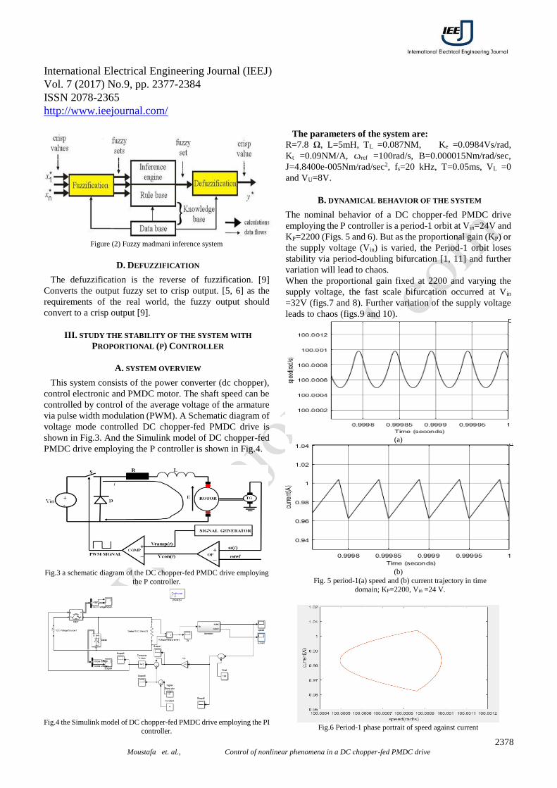
Fuzzy logic controller (FLC) consists of fuzzification
interface, fuzzy control rules, inference engine and
defuzzification interface as shown in fig.1 [4].
Fig. 1 the basic structure of fuzzy logic controller
Where x1, x2 are the inputs of the FLC, uf is fuzzy control
action, u is the crisp control action and G1, G2, Gu are gains of
input and output.
A. FUZZIFICATION
The fuzzification strategy converts the crisp input data into
fuzzy sets (linguistic variables) and consists of membership
functions that describe the fuzzy rules. These functions can
be triangle, trapezoidal, quasi-linear and Gaussian shaped.
The triangular-shaped is usually used as membership.
B. FUZZY CONTROL RULES
We represent the fuzzy control rules by the form:
IF (Process state) THEN (actions can be inferred)
This describe what action should be taken from currently
information, which includes both input and feedback if a
closed-loop control system is applied [5, 6].
C. INFERENCE ENGINE
Converts the input fuzzy sets to the output fuzzy set. The
most important two types of fuzzy inference method are
Mamdani and Sugeno fuzzy inference methods [5, 6].
Fuzzy madmani inference system is shown in fig.2
Control of Nonlinear Phenomena in a
DC Chopper-Fed PMDC Drive
Eman Moustafa1, Belal Abou-Zalam2, Abdel-Azem Sobaih3
Industrial Electronics and Control Engineering Department, Faculty of Electronic Engineering
International Electrical Engineering Journal (IEEJ)
Vol. 7 (2017) No.9, pp. 2377-2384
ISSN 2078-2365
http://www.ieejournal.com/
2384 Moustafa et. al., Control of nonlinear phenomena in a DC chopper-fed PMDC drive
(b)
Fig.26 period-1 (a) speed and (b) current trajectories in time domain at
Vin =57 V.
Fig.27 Period-1 phase portrait of speed against current at Vin =57 V.
(a)
(b)
Fig.28 period-1 (a) speed and (b) current trajectories in time domain at
Vin =65 V.
Fig.29 Period-1 phase portrait of speed against current at Vin =65 V.
VI. CONCLUSIONS
In this paper we use waveforms and phase portrait to study
the occurrence of nonlinear phenomena.
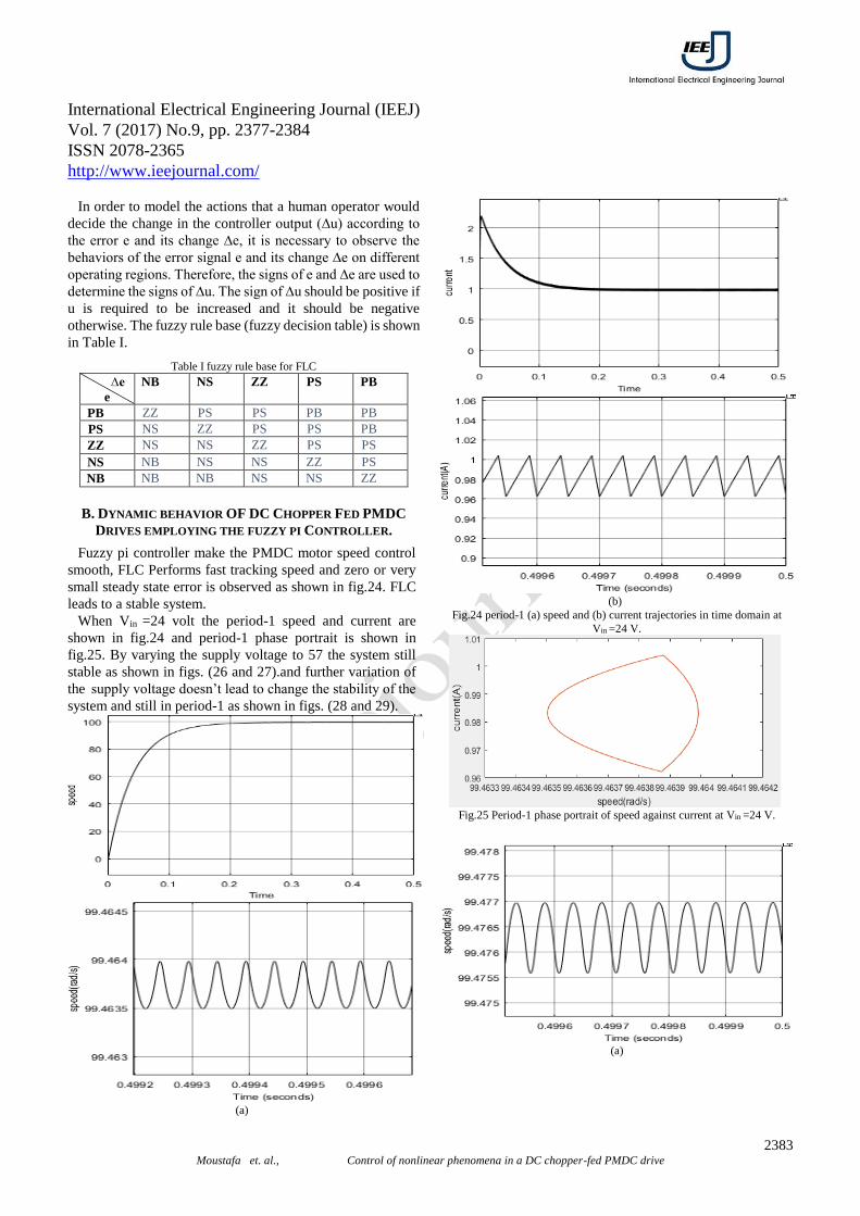
Fuzzy pi controller make the PMDC motor speed control
smooth, FLC Performs fast tracking speed and zero or very
small steady state error is observed. FLC leads to a stable
system as shown in V.
REFERENCES
[1] E. Moustafa, B. Abou-zalam, and A. Sobaih, “Study and Analysis of Nonlinear Phenomena in Electric Drives,” International Electrical Engineering Journal(IEEJ), vol. 7, no. 7, pp. 2304–2312, 2016.
[2] J. Chakravorty and R. Sharma, “Fuzzy Logic Based Method of Speed Control of DC Motor,” ijetae, vol. 3, no. 4, pp. 64–66, 2013.
[3] I. H. Altas and A. M. Sharaf, “A GENERALIZED DIRECT APPROACH FOR DESIGNING FUZZY LOGIC CONTROLLERS IN MATLAB / SIMULINK GUI ENVIRONMENT,” Int. J. Inf. Technol. Intell. Comput., vol. 1, no. 4,2007.
[4] J. M. Mendel, “Fuzzy logic systems for Engineering: A tutorial”, IEEE Trans, Sys. Man and Cyber, Vol. 83, No. 3, PP. 345-377, 1995.
[5] Y. Bai and D. Wang, “Fundamentals of Fuzzy Logic Control – Fuzzy Sets, Fuzzy Rules and Defuzzifications,” 1982, pp. 17–36.
[6] H. T. Nguyen, N. R. Prasad, C. L. Walker, and E. A. Walker, “A First Course in FUZZY and NEURAL CONTROL,” 2003.
[7] G.T.P.Naidu, R.Vijaya Santhi and I.Nikhil Kumar3, “Design of Fuzzy Pi Controller for the Speed Control of PMDC Motor,” IRJET, vol. 2, no. 6, pp. 520–525, 2015.
[8] Maan M. Shaker, “Design and Implementation of Fuzzy Logic system for DC motor Speed Control,” Iraq J. Electr. Electron. Eng., vol. 6, no. 2, pp. 123–130, 2010.
[9] J PRAKASH RANA and S JAIN, “DESIGN AND SIMULATION OF DIFFERENT CONTROLLERS FOR SPEED CONTROL OF CHOPPER FED DC MOTOR” Department of Electrical Engineering National Institute of Technology Rourkela, 2013.
[10] N. C. Okafor, “Analysis and Control of Nonlinear Phenomena in Electrical Drives,” School of Electrical, Electronic and Computer Engineering, Newcastle University, 2012.
[11]S. Iqbal, M. Ahmed, and S. A. Qureshi, “Investigation of Chaotic Behavior in DC-DC Converters,” vol. 1, no. 9, 2007.
[12] G. Chen, “chaos: control and anti-control,” ieee, vol. 9, no. 1, 1998.
[13] K.D.Sharma, Sh.Sharma and M.Ayyub, “Design of Different Fuzzy Controllers for Delayed Systems,” International Electrical Engineering Journal(IEEJ), vol. 6, no. 12, 2016.