ORIGINAL ARTICLE Control of welding distortion during gas metal arc welding of AH36 plates by stress engineering A. M. A. Pazooki 1 & M. J. M. Hermans 2 & I. M. Richardson 2 Received: 13 February 2016 /Accepted: 2 May 2016 /Published online: 14 May 2016 # The Author(s) 2016. This article is published with open access at Springerlink.com Abstract Welding residual stress and distortion are strongly linked together. One of the ways to control or reduce the welding distortions is the manipulation of the generated stresses during welding, and final residual stresses exist in the workpiece (stress engineering). In this paper, the control of gas metal arc butt welding distortion of 500 × 250 × 6 mm 3 AH36 plates by means of additional heat sources is studied using experimental and numerical approaches. To understand the distortion reduction mech- anism, 3D finite element model has been constructed and validated by temperature, distortion and residual stress measurements together with microstructure investigation. The numerical results are compared to that of the experi- mental measurements. Keywords Welding with additional heating . Side heating . Residual stress . Welding distortion . FEM . AH36 1 Background Welding distortion is a permanent change in shape of a component (or an instability) due to the welding-induced stresses [1, 2]. Six types of welding distortion are defined [2, 3]: & Transverse shrinkage (shrinkage perpendicular to the weld) & Longitudinal shrinkage (shrinkage in the direction of the weld) & Rotational distortion (angular distortion in the plane of the plate due to thermal expansion or contraction) & Angular distortion (shrinkage caused by a non-uniform temperature distribution in the through-thickness direction of the workpiece) & Bending distortion (distortion in a plane through the weld line and perpendicular to the plate) & Buckling (distortion caused by compressive stresses) Figure 1 shows the different types of welding distortion [4]. It should be mentioned that in reality, multiple types of welding distortion may occur at the same time and that it is sometimes difficult to distinguish the types of distortion pres- ent in a workpiece [4]. As reported in [5], in 1990, a Japanese Patent showed a method to reduce buckling deformation for thin metal sheet using additional heating sources parallel to the welding torch located at or near plates’ edges. The meth- od is applicable for the materials with thickness higher than 4 mm. Since the heaters are located rather far to the welding torch, the method is called side heating. In this paper, attempts have been made to study the welding with additional heating of AH36 plates with dimensions of 500 × 250 × 6 mm 3 . Both experimental and numerical approaches have been used in this investigation. The results of such approaches are compared for two situa- tions: (1) conventional welding and (2) welding with additional heating. * A. M. A. Pazooki [email protected]1 Material innovation institute (M2i), Elektronicaweg 25, 2628 XG Delft, The Netherlands 2 Department of Material Science and Engineering, Delft University of Technology, Mekelweg 2, 2628CD Delft, The Netherlands Int J Adv Manuf Technol (2017) 88:1439–1457 DOI 10.1007/s00170-016-8869-9
Transcript
ORIGINAL ARTICLE
Control of welding distortion during gas metal arc weldingof AH36 plates by stress engineering
A. M. A. Pazooki1 & M. J. M. Hermans2 & I. M. Richardson2
Received: 13 February 2016 /Accepted: 2 May 2016 /Published online: 14 May 2016# The Author(s) 2016. This article is published with open access at Springerlink.com
Abstract Welding residual stress and distortion arestrongly linked together. One of the ways to control orreduce the welding distortions is the manipulation of thegenerated stresses during welding, and final residualstresses exist in the workpiece (stress engineering). In thispaper, the control of gas metal arc butt welding distortionof 500 × 250 × 6 mm3 AH36 plates by means of additionalheat sources is studied using experimental and numericalapproaches. To understand the distortion reduction mech-anism, 3D finite element model has been constructed andvalidated by temperature, distortion and residual stressmeasurements together with microstructure investigation.The numerical results are compared to that of the experi-mental measurements.
Keywords Weldingwith additional heating . Side heating .
Residual stress .Welding distortion . FEM . AH36
1 Background
Welding distortion is a permanent change in shape of acomponent (or an instability) due to the welding-induced
stresses [1, 2]. Six types of welding distortion are defined[2, 3]:
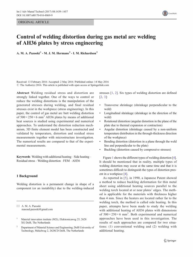
& Transverse shrinkage (shrinkage perpendicular to theweld)
& Longitudinal shrinkage (shrinkage in the direction of theweld)
& Rotational distortion (angular distortion in the plane of theplate due to thermal expansion or contraction)
& Angular distortion (shrinkage caused by a non-uniformtemperature distribution in the through-thickness directionof the workpiece)
& Bending distortion (distortion in a plane through the weldline and perpendicular to the plate)
& Buckling (distortion caused by compressive stresses)
Figure 1 shows the different types of welding distortion [4].It should be mentioned that in reality, multiple types ofwelding distortion may occur at the same time and that it issometimes difficult to distinguish the types of distortion pres-ent in a workpiece [4].
As reported in [5], in 1990, a Japanese Patent showeda method to reduce buckling deformation for thin metalsheet using additional heating sources parallel to thewelding torch located at or near plates’ edges. The meth-od is applicable for the materials with thickness higherthan 4 mm. Since the heaters are located rather far to thewelding torch, the method is called side heating. In thispaper, attempts have been made to study the weldingwith additional heating of AH36 plates with dimensionsof 500 × 250 × 6 mm3. Both experimental and numericalapproaches have been used in this investigation. Theresults of such approaches are compared for two situa-tions: (1) conventional welding and (2) welding withadditional heating.
AH36 steel is a grade of ASTM A131 steel. This is amoderate strength hot rolled steel, mainly used in ship-building [6]. The steel has a ferritic-pearlitic microstruc-ture. The material undergoes solid state phase transforma-tions during welding. Table 1 shows the chemical compo-sition of such steel.
3 Conventional welding and welding with additionalheating
AH36 plates with dimension of 500 × 250 × 6 mm3 werewelded by means of gas metal arc welding (GMAW).The welding power source was a Cloos-Quinto Profi503. The welding torch was tilted to an angle of around60° to the plane of the plate (leading the weld pool). ALincoln electric LNM 25TM filler wire with a diameterof 1.2 mm was used. According to AWS A5.18 speci-fication [7], the electrode is classified as ER70S-3 witha chemical composition given in Table 2.
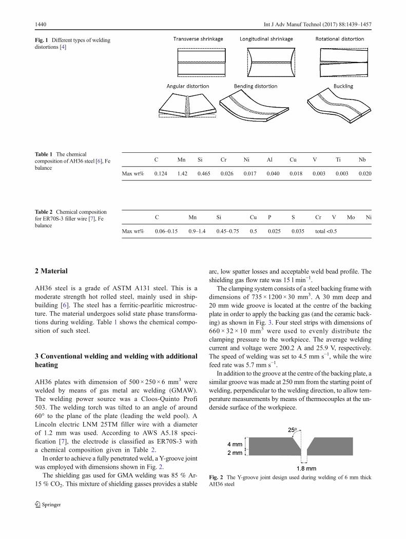
In order to achieve a fully penetrated weld, a Y-groove jointwas employed with dimensions shown in Fig. 2.
The shielding gas used for GMA welding was 85 % Ar-15 % CO2. This mixture of shielding gasses provides a stable
arc, low spatter losses and acceptable weld bead profile. Theshielding gas flow rate was 15 l min−1.
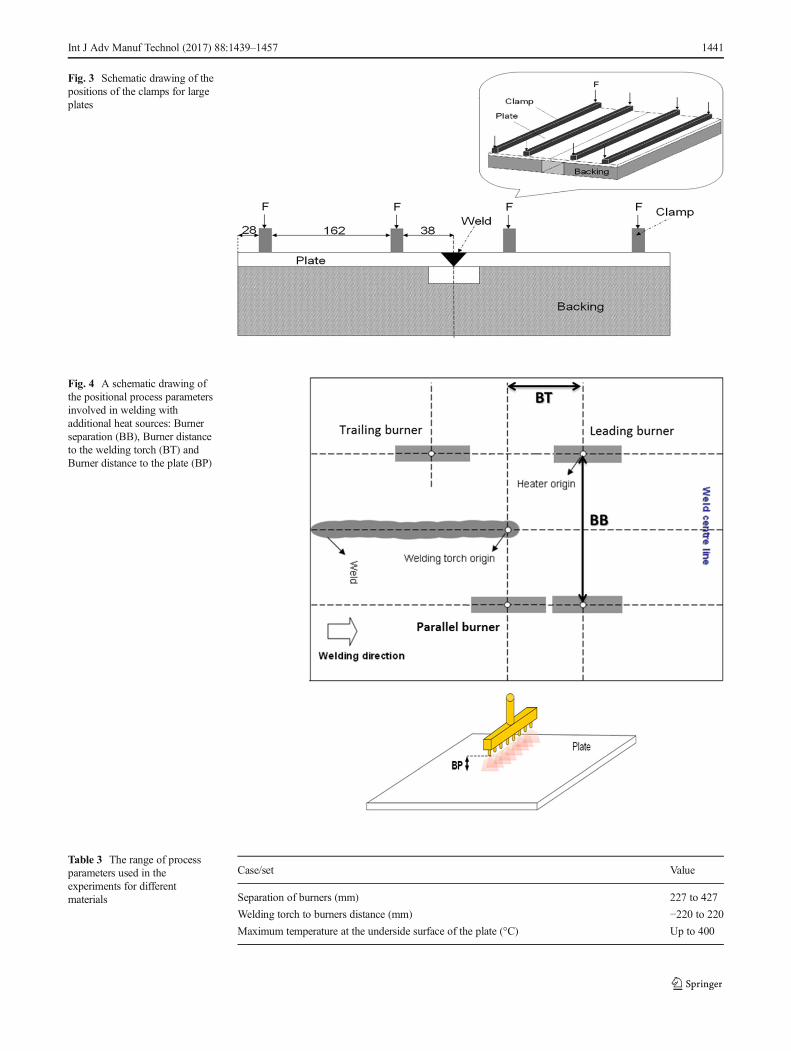
The clamping system consists of a steel backing frame withdimensions of 735 × 1200 × 30 mm3. A 30 mm deep and20 mm wide groove is located at the centre of the backingplate in order to apply the backing gas (and the ceramic back-ing) as shown in Fig. 3. Four steel strips with dimensions of660 × 32 × 10 mm3 were used to evenly distribute theclamping pressure to the workpiece. The average weldingcurrent and voltage were 200.2 A and 25.9 V, respectively.The speed of welding was set to 4.5 mm s−1, while the wirefeed rate was 5.7 mm s−1.
In addition to the groove at the centre of the backing plate, asimilar groove was made at 250 mm from the starting point ofwelding, perpendicular to the welding direction, to allow tem-perature measurements by means of thermocouples at the un-derside surface of the workpiece.
Fig. 1 Different types of weldingdistortions [4]
Table 1 The chemicalcomposition of AH36 steel [6], Febalance
Table 2 Chemical compositionfor ER70S-3 filler wire [7], Febalance
C Mn Si Cu P S Cr V Mo Ni
Max wt% 0.06–0.15 0.9–1.4 0.45–0.75 0.5 0.025 0.035 total <0.5
Fig. 2 The Y-groove joint design used during welding of 6 mm thickAH36 steel
1440 Int J Adv Manuf Technol (2017) 88:1439–1457
Fig. 4 A schematic drawing ofthe positional process parametersinvolved in welding withadditional heat sources: Burnerseparation (BB), Burner distanceto the welding torch (BT) andBurner distance to the plate (BP)
Table 3 The range of processparameters used in theexperiments for differentmaterials
Case/set Value
Separation of burners (mm) 227 to 427
Welding torch to burners distance (mm) −220 to 220
Maximum temperature at the underside surface of the plate (°C) Up to 400
Fig. 3 Schematic drawing of thepositions of the clamps for largeplates
Int J Adv Manuf Technol (2017) 88:1439–1457 1441
In welding with additional heating, the burners can beinstalled either parallel or perpendicular to the weld centreline. It was practically impossible to test the burner as-sembly perpendicular to the weld centre line due to geo-metric limitations. Therefore, in all experiments, theburners were installed parallel to the weld centre line asshown in Fig. 4.
The new set-up was based on the rectangularLINDOFLAMM® (http://www.lindegas.com/) special shortlance burners. The burner operates according to DIN ENISO 5172 [8] with compressed air and acetylene. Basically,it consists of a burner head, a mixing pipe, a mixing chamberwith a pressure regulator and a handle. The total length of theburner is 240 mm and includes eight nozzles with 30-mmseparation distance. The width of the burner is 27 mm. The
working pressure at the burner inlet is 0.5 bar for acetyleneand 1.5–4.0 bar for compressed air. This gives a consumptionof 0.3–3.2 m3 h−1 for acetylene and 2.1–22.4 m3 h−1 for com-pressed air. The burners were adjusted by turning the acety-lene and oxygen valves on the regulator to control the gas flowand to obtain the required flame for welding with additionalheating.
The first step in the experiments is the setting of theburners for different peak temperatures. The maximumtemperatures for different burner settings were measuredat the underside surface of the plate by means of thermo-couples. A series of trials was performed for a number ofpressurised air-acetylene flame settings, i.e., differentpeak temperatures. In this way, the mixtures were calibrat-ed for different peak temperatures. These tests were re-peated for the different base materials. Table 3 showsthe range of the maximum temperatures obtained and po-sition parameters.
The distance of the burners to the plate (BP) was setto 40 mm for AH36 sheets in order to increase the heatinput.
Table 4 Parameter values used in the simulation
Parameter Value
Welding source half width (mm) 5
Welding source depth (mm) 6
Welding source forward length 10
Welding source backward length 5
Efficiency of the welding process 75 %
Welding power (W) 5185.18
Max heat flux in additional heating (kW m−2) 375.4
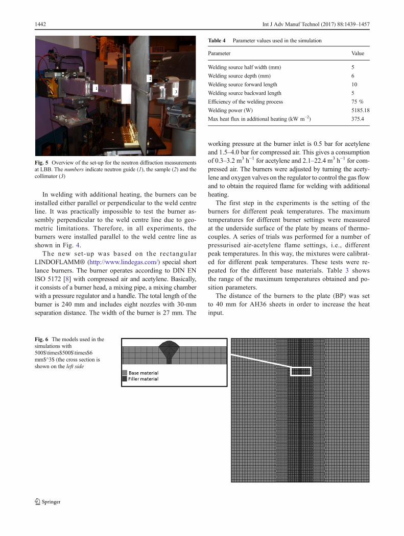
Fig. 5 Overview of the set-up for the neutron diffraction measurementsat LBB. The numbers indicate neutron guide (1), the sample (2) and thecollimator (3)
Fig. 6 The models used in thesimulations with500$\times$500$\times$6mm$^3$ (the cross section isshown on the left side
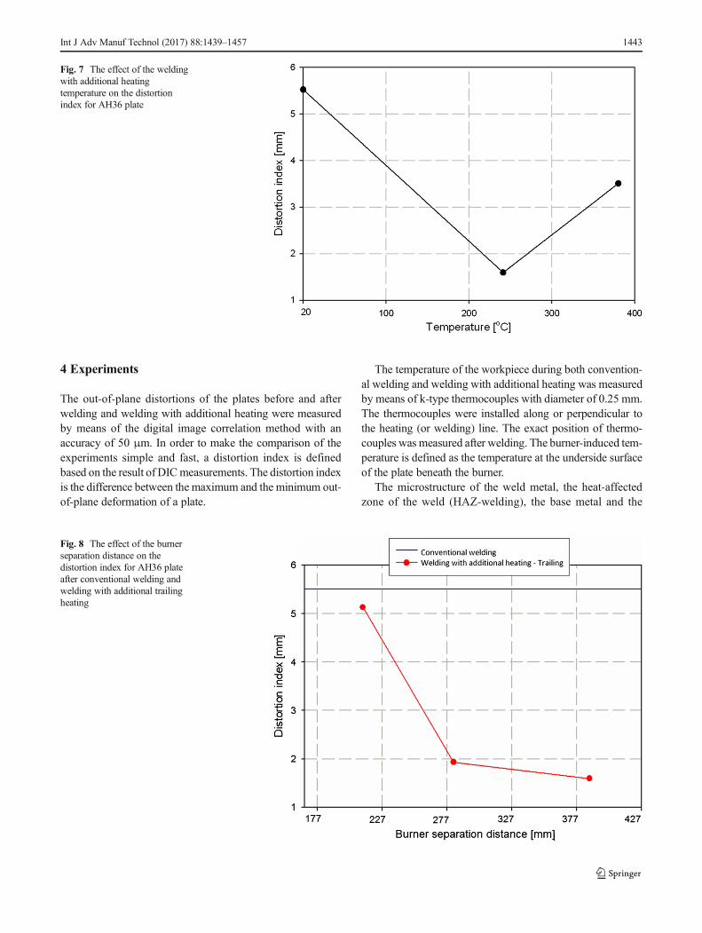
The out-of-plane distortions of the plates before and afterwelding and welding with additional heating were measuredby means of the digital image correlation method with anaccuracy of 50 μm. In order to make the comparison of theexperiments simple and fast, a distortion index is definedbased on the result of DICmeasurements. The distortion indexis the difference between the maximum and the minimum out-of-plane deformation of a plate.
The temperature of the workpiece during both convention-al welding and welding with additional heating was measuredby means of k-type thermocouples with diameter of 0.25 mm.The thermocouples were installed along or perpendicular tothe heating (or welding) line. The exact position of thermo-couples was measured after welding. The burner-induced tem-perature is defined as the temperature at the underside surfaceof the plate beneath the burner.
The microstructure of the weld metal, the heat-affectedzone of the weld (HAZ-welding), the base metal and the
Fig. 8 The effect of the burnerseparation distance on thedistortion index for AH36 plateafter conventional welding andwelding with additional trailingheating
Fig. 7 The effect of the weldingwith additional heatingtemperature on the distortionindex for AH36 plate
Int J Adv Manuf Technol (2017) 88:1439–1457 1443
heated area beneath the burners (HAZ-welding withadditional heating) were studied at a cross section perpendic-ular to the weld and in the middle of the plate using a 5%Nitaletching solution for 10 s. Hardness profiles were also takenacross the welds, the heat-affected zones and the heated areasbeneath the additional heating burners, for different materialsusing Vickers micro-hardness measurements with an indenta-tion load of 300 g.
Residual stress measurements were performed bymeans of the neutron diffraction (ND) method at theLaboratoire Leon Brillouin (LLB) France. The sampleswere welded conventionally and welding with additionalheating and full penetration was obtained. Figure 5 showsa picture of the arrangement. The diffraction measure-ments were performed on the Fe(211). This plane isknown to be the least sensitive to the inter-granular stresseffects. The residual stress profile of samples in the
clamped condition was measured using a portable X-rayequipment.
5 Numerical approach
The numerical approach is based on 3D decoupled thermo-mechanical finite element model for both conventionalwelding and welding with additional heating usingMsc.Marc as the commercial code.
The thermal model includes the modelling of thewelding heat by the volumetric heat flux with Gaussiandistribution proposed by Goldak [9] input and the model-ling of heat losses by convection, radiation and conduc-tion. The burners in welding with side heating aremodelled by eight circular Gaussian heat flux distribu-tions with an inter-distance of 30 mm. The suitable power
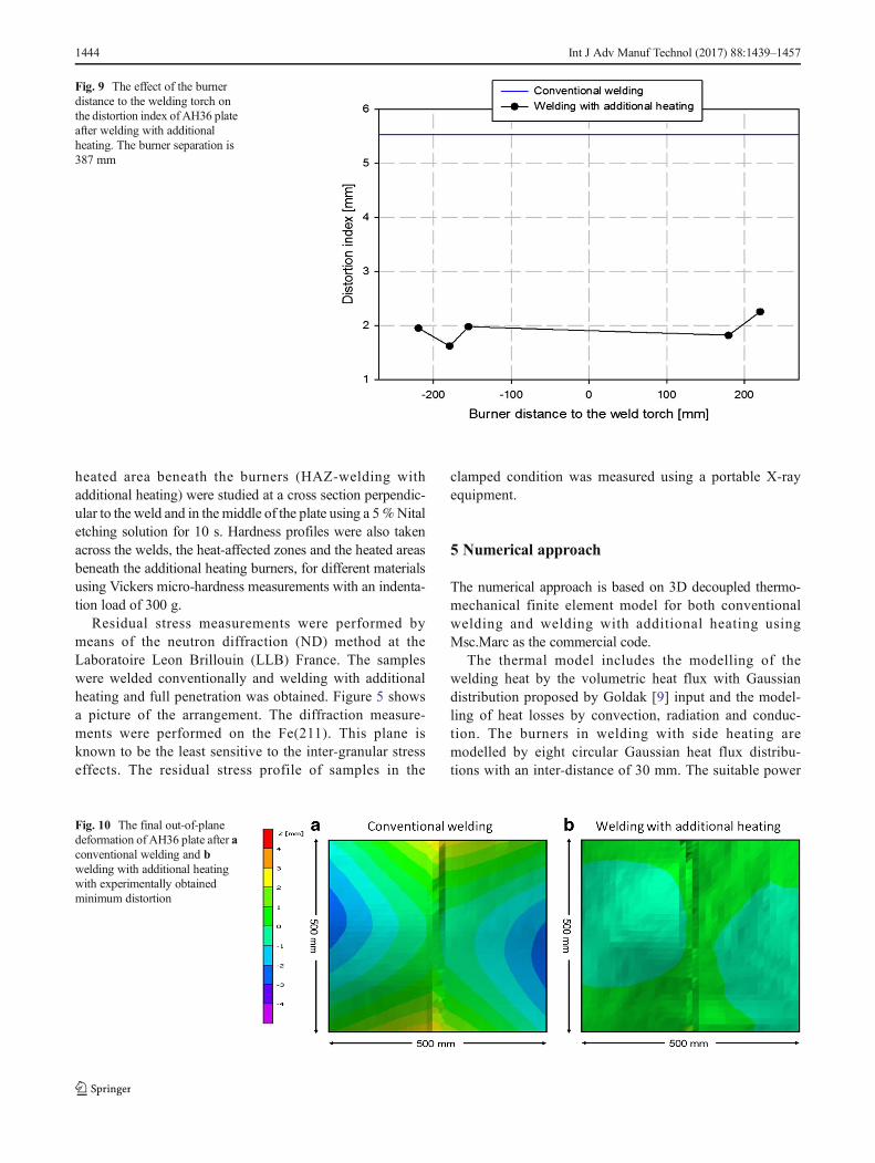
Fig. 9 The effect of the burnerdistance to the welding torch onthe distortion index of AH36 plateafter welding with additionalheating. The burner separation is387 mm
Fig. 10 The final out-of-planedeformation of AH36 plate after aconventional welding and bwelding with additional heatingwith experimentally obtainedminimum distortion
1444 Int J Adv Manuf Technol (2017) 88:1439–1457
density distribution is obtained by comparing the temper-ature predictions and measurements. The mesh used in thesimulations is shown in Fig. 6. The parameters for thermalmodelling are summarised in Table 4. The thermal mate-rial properties were obtained from [10] and [11].
The mechanical models for both conventional welding andwelding with additional heating consist of the modelling ofclamps using spring links and plastic strain resetting at meltingtemperature. Isotropic hardening model was used in themodels. The mechanical material properties are obtainedusing data from [12].
The filler wire is modelled using the deactivated ele-ment method. This means that filler elements are initiallyavailable in the model with scaled down material proper-ties. The filler elements are only thermally activated ini-tially and remain inactive on the mechanical side. If the
thermal activation time is zero, the filler elements areactivated on the mechanical side in the next increment.If the thermal activation time is non-zero, the filler ele-ments remain mechanically inactive until the thermal ac-tivation time is passed [13].
6 Experimental results and discussion
The temperature effect of additional heating on the distor-tion index for AH36 plate is shown in Fig. 7. The con-ventional welding has a distortion index of 5.5 mm. Byincreasing the burner-induced temperature, the distortionindex is decreased first and then it starts to increase. Thesuitable temperature was found to be around 240 °C. Thistemperature is used for the other additional heating
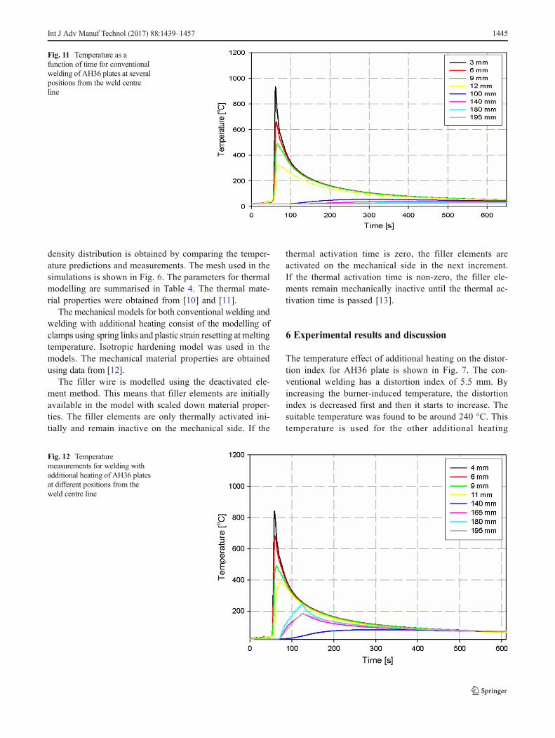
Fig. 12 Temperaturemeasurements for welding withadditional heating of AH36 platesat different positions from theweld centre line
Fig. 11 Temperature as afunction of time for conventionalwelding of AH36 plates at severalpositions from the weld centreline
Int J Adv Manuf Technol (2017) 88:1439–1457 1445
experiments. The effect of the burner separation on thedistortion index is shown in Fig. 8. The distortion index
decreases when the burners are located 193.5 mm to theweld centre line. The distance of the burners to the
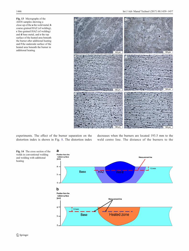
Fig. 14 The cross section of thewelds in conventional weldingand welding with additionalheating
Fig. 13 Micrographs of theAH36 samples showing aclose-up of the a the weldmetal, bcoarse-grained HAZ (of welding),c fine-grained HAZ (of welding)and d base metal, and e the topsurface of the heated area beneaththe burner after additional heatingand f the underside surface of theheated area beneath the burner inadditional heating
1446 Int J Adv Manuf Technol (2017) 88:1439–1457
welding torch was varied. The results are shown in Fig. 9.The leading and the trailing positions of the burners bothreduce the distortion index, but there is hardly any effect.The case in which the burners are located 180 mm trailingthe welding torch is selected as the case with experimen-tally obtained minimum deformation. The out-of-planedeformation of the plate after conventional welding iscompared to that of welding with additional heating forthe selected case in Fig. 10. As can be seen, welding withadditional heating reduces the plate deformation.
Figure 11 shows the temperature as a function of time atdifferent positions from the weld centre line for conventionalwelding of AH36 samples, while the temperature profile
during welding with additional heating of such samples isshown in Fig. 12.
Figure 13 shows the micrograph of the weld metal, coarse-grained HAZ (of welding), fine-grained HAZ (of welding),and the base metal of both conventionally welded materialand welded material with additional heating. The heated areasbeneath the burners in the case of welding with additionalheating for both the top and underside surfaces of the sampleare shown in the figure. Welding with additional heating hasno influence on the microstructure of the weld metal and theHAZ (of welding). This is because of the similar thermal his-tories of the weld and HAZ (of welding) for both cases. It canbe seen that the top surface of the heated area beneath the
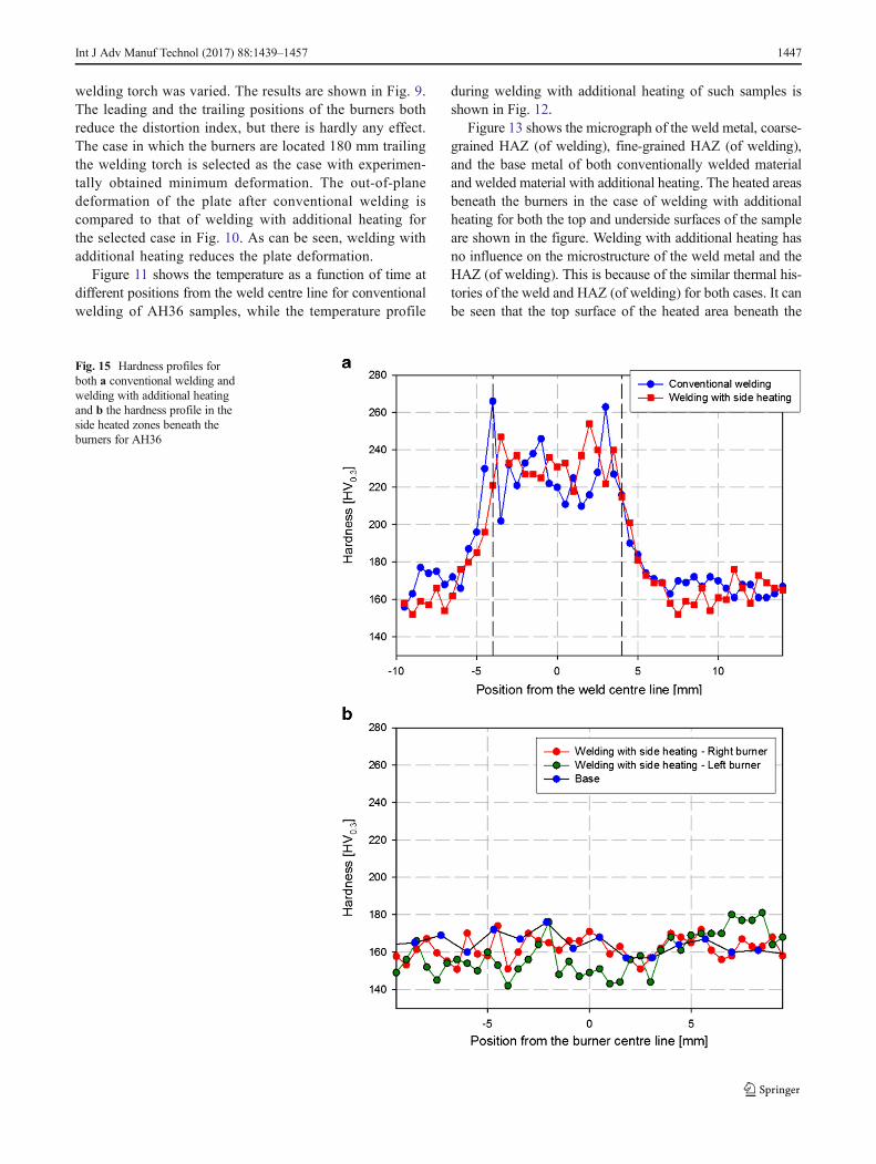
Fig. 15 Hardness profiles forboth a conventional welding andwelding with additional heatingand b the hardness profile in theside heated zones beneath theburners for AH36
Int J Adv Manuf Technol (2017) 88:1439–1457 1447
burners has a tempered, while the underside surface has amicrostructure close to the base metal.
Hardness profiles were measured at locations shown inFig. 14. The hardness profile of the weld, HAZ (ofwelding) and the base metal for conventional weldingand welding with additional heating is shown in Fig. 15a,while the hardness of the heated area beneath the burners isshown in Fig. 15b. The hardness of the heated area beneaththe burners is slightly reduced. It is expected that such areduction is due to tempering and reduction of internalenergy.
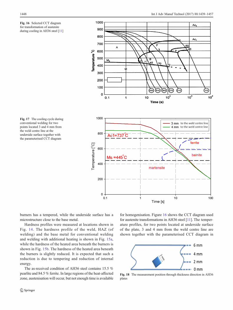
The as-received condition of AH36 steel contains 15.5 %pearlite and 84.5% ferrite. In large regions of the heat-affectedzone, austenisation will occur, but not enough time is available
for homogenisation. Figure 16 shows the CCT diagram usedfor austenite transformations in AH36 steel [11]. The temper-ature profiles, for two points located at underside surfaceof the plate, 3 and 4 mm from the weld centre line areshown together with the parameterised CCT diagram in
Fig. 16 Selected CCT diagramfor transformation of austeniteduring cooling in AH36 steel [11]
Fig. 17 The cooling cycle duringconventional welding for twopoints located 3 and 4 mm fromthe weld centre line at theunderside surface together withthe parameterised CCT diagram
Fig. 18 The measurement position through thickness direction in AH36plates
1448 Int J Adv Manuf Technol (2017) 88:1439–1457
Fig. 17. The temperature profiles are related to the points atthe underside surface of the plate. As can be seen from thefigure, at these two locations, the formation of hard constitu-ents (like bainite) is expected.
The longitudinal residual stresses were measured perpen-dicular to the welding direction as a function of distance fromthe weld centre line. The origin is set at the plate centre. Therolling direction of the material is along the longitudinal di-rection. The position of the measurement in the through thick-ness direction is shown in Fig. 18. A gauge volume of2×2×2 mm3 was used here.
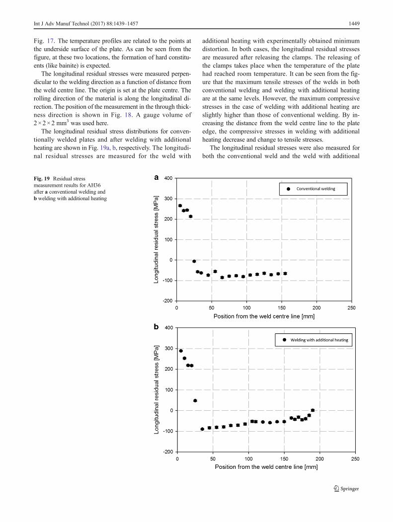
The longitudinal residual stress distributions for conven-tionally welded plates and after welding with additionalheating are shown in Fig. 19a, b, respectively. The longitudi-nal residual stresses are measured for the weld with
additional heating with experimentally obtained minimumdistortion. In both cases, the longitudinal residual stressesare measured after releasing the clamps. The releasing ofthe clamps takes place when the temperature of the platehad reached room temperature. It can be seen from the fig-ure that the maximum tensile stresses of the welds in bothconventional welding and welding with additional heatingare at the same levels. However, the maximum compressivestresses in the case of welding with additional heating areslightly higher than those of conventional welding. By in-creasing the distance from the weld centre line to the plateedge, the compressive stresses in welding with additionalheating decrease and change to tensile stresses.
The longitudinal residual stresses were also measured forboth the conventional weld and the weld with additional
Fig. 19 Residual stressmeasurement results for AH36after a conventional welding andb welding with additional heating
Int J Adv Manuf Technol (2017) 88:1439–1457 1449
heating in the clamped conditions. In Fig. 20a, the result ofthe stress measurement for conventional welding for theplate in the clamped condition is shown and comparedto the plate after releasing the clamps. It is seen that theabsolute values of both tensile and compressive stresses arehigher when the plate is in the clamped condition. The stressmeasurement for the plate before and after releasing theclamps in the case of the weld with additional heating isshown in Fig. 20b. The tensile stresses are higher in theclamped condition. However, the compressive stresses inthe clamped condition are close to the un-clamped cases. Inorder to interpret the results, numerical models for bothcases are used and discussed in the next section. Only fromthe experimental point of view, such deviations (between
clamped and clamped release stress measurements) can beattributed to errors in the measurement. The results of thestress measurement for the clamped conditions were ob-tained from portable X-ray equipment (only at the platesurface). Therefore, different measurement methods arecompared in the figure.
The main sources of errors in the measurements can besummarised as:
& For thick material, an error is introduced by the sim-plification of the 3D stress tensor to in-plane stresscondition
& Human-related errors: sample positioning, alignment,reading and typing errors, etc.
Fig. 20 Residual stressmeasurement results for AH36 inthe clamped condition for a aconventional weld and b a weldwith additional heating
1450 Int J Adv Manuf Technol (2017) 88:1439–1457
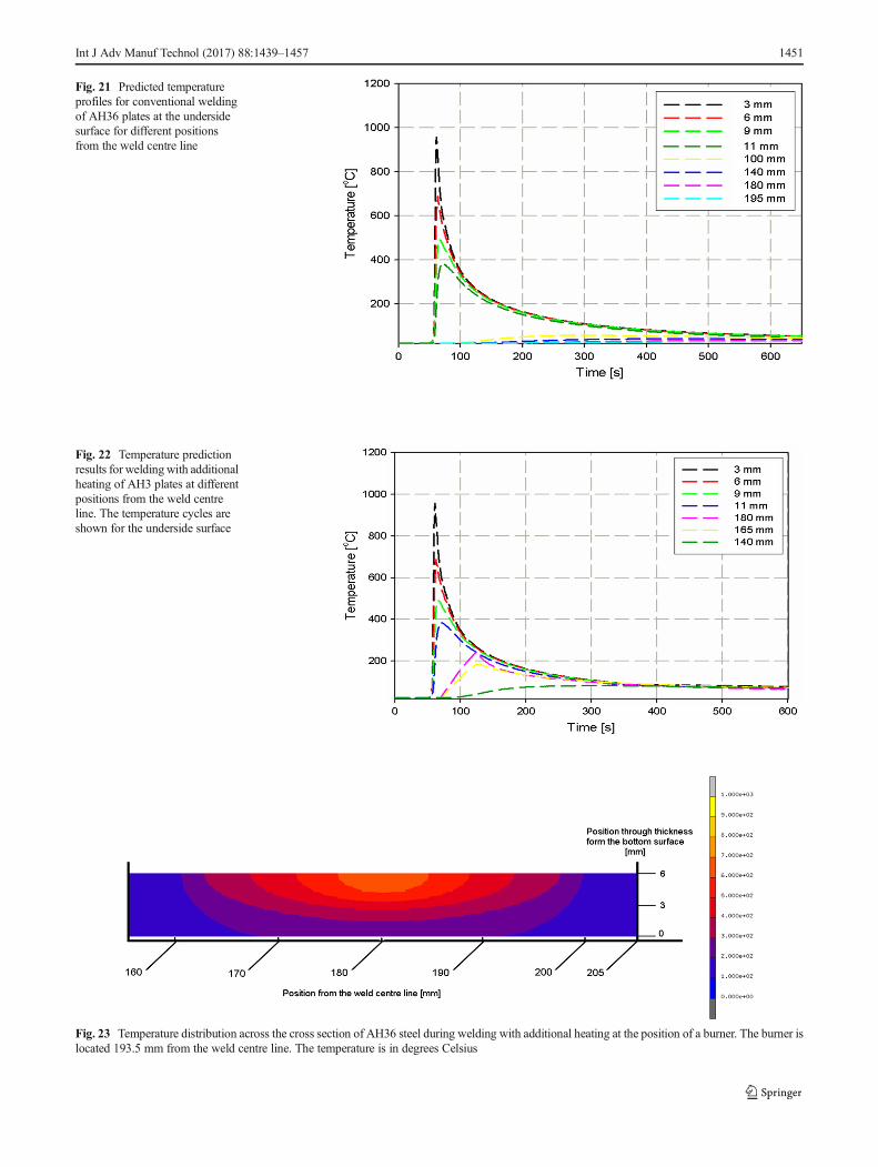
Fig. 21 Predicted temperatureprofiles for conventional weldingof AH36 plates at the undersidesurface for different positionsfrom the weld centre line
Fig. 22 Temperature predictionresults for weldingwith additionalheating of AH3 plates at differentpositions from the weld centreline. The temperature cycles areshown for the underside surface
Fig. 23 Temperature distribution across the cross section of AH36 steel during welding with additional heating at the position of a burner. The burner islocated 193.5 mm from the weld centre line. The temperature is in degrees Celsius
Int J Adv Manuf Technol (2017) 88:1439–1457 1451
& Sample positioning errors: definition of the origin, sampledeformation, etc.
& Data analysis errors: peak fitting errors, elastic constants,stress-free lattice parameter, etc.
& Measurement errors: errors from neutron source, errorsfrom measurement system (displacement), etc.
& Errors from sample: texture, grain size, shear stresses, out-of-plane stresses, etc.
7 Numerical predictions and discussions
The heat input and heat loss model parameters have been setby comparing the results of the simulations with the experi-mental temperature measurements. Therefore, a trial and errormethod has been used to fit the numerical output to the exper-imental results by variations in the parameters. The predictedtemperature profile during conventional welding of AH36 at
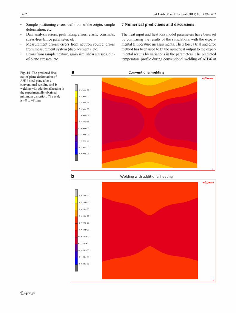
Fig. 24 The predicted finalout-of-plane deformation ofAH36 steel plate after aconventional welding and bwelding with additional heating inthe experimentally obtainedminimum distortion. The scaleis −8 to +8 mm
1452 Int J Adv Manuf Technol (2017) 88:1439–1457
different positions from the weld centre line is shown inFig. 21.
The prediction results of the temperature profile duringwelding with additional heating are shown in Fig. 22. Thepredictions are in a good agreement with the temperaturemeasurements.
Figure 23 shows the prediction through thickness tempera-ture distribution of AH36 plate beneath the burner duringwelding with additional heating. The burners are located193.5 mm from the weld centre line. The maximum predictedtemperature at the top surface of the plate beneath the burnerswhenweldingwith additional heating for thismaterial is 610 °C.
Figure 24 shows the numerical results for the out-of-planedeformation of AH36 steel after welding and welding with
additional heating. The welding with additional heating wasmodelled using the experimentally obtained minimum distor-tion (trailing case). It is clear that the out-of-plane deformationof the plate is reduced using additional heating.
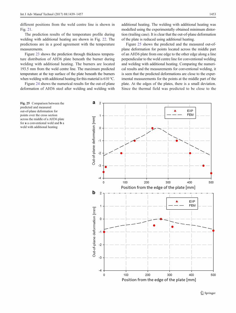
Figure 25 shows the predicted and the measured out-of-plane deformation for points located across the middle partof an AH36 plate from one edge to the other edge along a lineperpendicular to the weld centre line for conventional weldingand welding with additional heating. Comparing the numeri-cal results and the measurements for conventional welding, itis seen that the predicted deformations are close to the exper-imental measurements for the points at the middle part of theplate. At the edges of the plates, there is a small deviation.Since the thermal field was predicted to be close to the
Fig. 25 Comparison between thepredicted and measuredout-of-plane deformation forpoints over the cross sectionacross the middle of a AH36 platefor a a conventional weld and b aweld with additional heating
Int J Adv Manuf Technol (2017) 88:1439–1457 1453
measured field, the main source of the deviation is related tothe mechanical field. This includes the material properties andthe clamping model explained before for the other twomaterials.
Table 5 shows the numerical results of the out-of-planedeformation of AH36 steel plate for different burner po-sitions. It can be seen that the trailing situation providesthe minimum distortion index both in the numerical andmeasurement results. The predictions are in agreementwith the experiments.
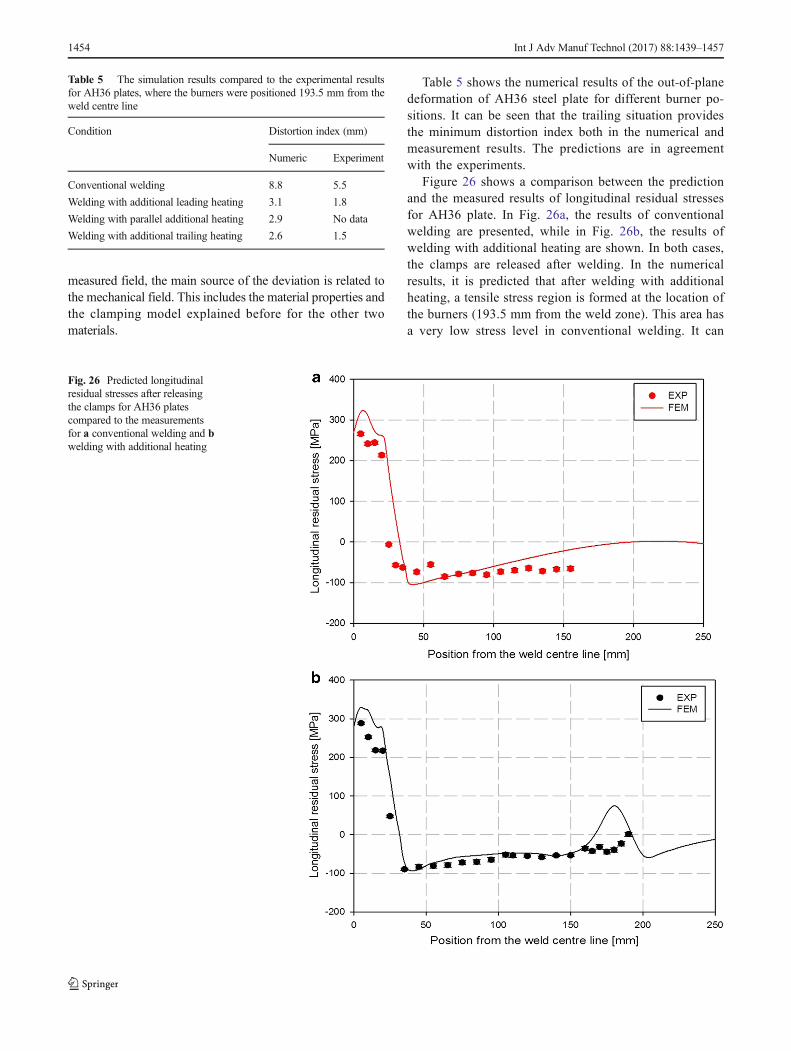
Figure 26 shows a comparison between the predictionand the measured results of longitudinal residual stressesfor AH36 plate. In Fig. 26a, the results of conventionalwelding are presented, while in Fig. 26b, the results ofwelding with additional heating are shown. In both cases,the clamps are released after welding. In the numericalresults, it is predicted that after welding with additionalheating, a tensile stress region is formed at the location ofthe burners (193.5 mm from the weld zone). This area hasa very low stress level in conventional welding. It can
Fig. 26 Predicted longitudinalresidual stresses after releasingthe clamps for AH36 platescompared to the measurementsfor a conventional welding and bwelding with additional heating
Table 5 The simulation results compared to the experimental resultsfor AH36 plates, where the burners were positioned 193.5 mm from theweld centre line
Condition Distortion index (mm)
Numeric Experiment
Conventional welding 8.8 5.5
Welding with additional leading heating 3.1 1.8
Welding with parallel additional heating 2.9 No data
Welding with additional trailing heating 2.6 1.5
1454 Int J Adv Manuf Technol (2017) 88:1439–1457
also be seen that the predictions indicate the same level ofstresses in the weld and its HAZ in both conventionalwelding and welding with additional heating. However,the experimental results show a significant lower residualstress for the region beneath the burners in welding withadditional heating. The main deviations between the nu-merical results and the experiments are attributed to thefollowing:
& There is a possibility that the heat generated by theburners causes stress relieving. The temperature of thetop surface beneath the burners is predicted to bearound 600 °C. The time of heating depends on thelength of the burner (240 mm) and the heating speed(4.5 mm s−1). Both temperature and time needed forstresses relieving are available. Therefore, it is expected
that two competing phenomena are occurring here: (1)stress build-up by the burners and (2) stress reduction bystress relieving. The winning term determines the finallevel of residual stresses. In the numerical model,phase transformations and microstructure changeshave been excluded. In the predicted results, suchtensile stress peaks at the position of the burnersare expected. Implementation of these small changesin the numerical models is difficult. It should benoted here that the hardness measurement does notshow significant change for the region beneath theburners. Full stress relieving needs more time thanthe heated time in the experiment. It is expected thatstress relieving phenomenon occurs partially for thisexperimental heating time. Similar results have beenobserved in [14].
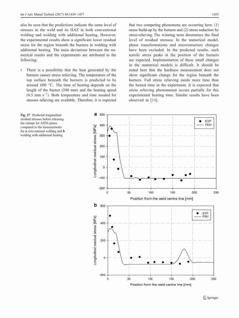
Fig. 27 Predicted longitudinalresidual stresses before releasingthe clamps for AH36 platescompared to the measurementsfor a conventional welding and bwelding with additional heating
Int J Adv Manuf Technol (2017) 88:1439–1457 1455
& The experimental source of errors explained in previoussection should be taken into account in the interpretation.
& The numerical models exclude the phase transformations.However, the experimental results show lower stress in theregion close to the weld in both conventional welding andwelding with additional heating. Since the residual stress-es are in a balanced condition, a change of these stressessomewhere in a plate causes a change somewhere else.
& All errors in material-related properties and the way ofclamping in the numerical models explained for previousmaterials are valid here as well.
Figure 27 shows a comparison between the predictionand the measured results of longitudinal residual stressesfor AH36 plate before releasing the clamps. In Fig. 27a,the results of conventional welding are presented, while inFig. 27b, the results of welding with additional heatingare shown. It is believed that the material properties con-tribute the most to the differences between the measuredand the modelled residual stresses. Finally, it should bementioned that the stresses have been measured only inthe longitudinal direction. If more information for residualstresses in other directions were available for this thickmaterial, it may be possible to determine more appropriatemodel parameters and obtain a better match between pre-dictions and experiments.
8 Conclusions
The mechanisms of distortion reduction in welding withadditional heating are complex. The complicated nature ofwelding stress and strain fields is increased by the largenumber of parameters involved in welding with additionalheating. In welding with additional heating, it was foundthat the closer the burners were to the weld centre line, thehigher deformation obtained. Moreover, the trend in dis-tortion as a function of the burner positions (leading, par-allel or trailing) relative to the welding torch was non-linear. The results of distortion measurements indicatedthat the distortion of the plates is less sensitive to thisparameter. The best temperature for welding with addi-tional heating depends on many factors such as the posi-tion of the burners, the thermal and the mechanical mate-rial properties, the clamping system around the weld, thearea heated by the burners, the geometry of the plate andthe welding process. It was seen that the thermal fieldaround the welds is not changed by additional heaters.The introduction of the additional heat by the burners islimited. Although at the top surface of the plate, highertemperatures are obtained. This causes minor changes inmicrostructure and mechanical properties. For AH36 steelplate, the top surface of the heated areas beneath the
burners showed a tempered microstructure, while the mi-crostructure of the underside surface is not affected. In theregion beneath and close to the burners, compressive re-sidual stresses are reduced in welding with side heatingcompared with those of conventional welding of AH36.Finite element models were constructed to simulate andinvestigate the thermal and the mechanical fields in bothconventional welding and welding with additionalheating. The assumptions made in the high temperaturematerial properties, plastic strain resetting, modelling ofclamps and the additional heaters resulted in some dis-crepancies between the models and the measurements.For the conventional welding process, close matches be-tween the temperature, residual stress and distortion mea-surements and the numerical predictions were observed.The main sources of deviation in the thermal modelling ofboth conventional welding and welding with side heatingare related to the thermal material data at elevated tem-perature. The essential feature of the welding with sideheating is the creation of a temperature peak at the loca-tion of the burners. The temperature distribution in theweld zone and the HAZ (of welding) remains unchanged.The predicted residual stresses are close to the measuredvalues for both conventionally welded plates and platesafter side heating. The characteristic of side heating froma numerical point of view is the creation of tensile resid-ual stresses at the location of the burners (tensile peakswere observed in the numerical results for the regionsbeneath the burners).
Acknowledgments This research was carried out under project numberMC8.06252 in the framework of the Research Program of the Materialsinnovation institute M2i (www.m2i.nl), the former Netherlands Institutefor Metals Research.
Open Access This article is distributed under the terms of theCreative Commons Attribution 4.0 International License (http://creativecommons.org/licenses/by/4.0/), which permits unrestricted use,distribution, and reproduction in any medium, provided you give appro-priate credit to the original author(s) and the source, provide a link to theCreative Commons license, and indicate if changes were made.
References
1. Preston RV (2000) Modelling of residual stresses in welded aero-space alloys. PhD thesis, University of Cambridge
2. Masubuchi K (1980) Analysis of welded structures. PergamonPress, USA
3. Pilipenko A (2001) Computer simulation of residual stress anddistortion of thick plates in multi-electrode submerged arc welding,PhD thesis. Norwegian University of Science and Technology(NTNU), Trondheim
4. van der Aa EM (2007) Local cooling during welding: predictionand control of residual stresses and buckling distortion. PhD thesis,Delft University of Technology.
5. Takeno SMethod for preventing welding distortion of sheet metals,Japanese Patent JP 4052079.
6. ASTM A 131/A 131 M-08: Standard Specification for StructuralSteel for Ships, ASTM International (http://www.astm.org/Standards/A131.htm).
7. AWS A5.18 (2001) Specification for Carbon Steel Electrodes andRods for Gas Shielded Arc Welding, AWS.
8. DIN EN ISO 5172 (2006) Gas welding equipment, Blowpipes forgas welding, heating and cutting-Specifications and tests.
9. Goldak J (1984) A finite element model for welding heat sources.Metallurgical Transactions 15B:299–305
10. Pilipenko A (2001) Computer simulation of residual stress anddistortion of thick plates in multi-electrode submerged arcwelding-Their mitigation techniques, PhD Thesis. NTNU,Trondheim
11. Tsirkas SA, Papanikos P, Kermanidis T (2003) Numericalsimulation of the laser welding process in the butt jointspecimens. Journal of Material Processing and Technology134:59–69
12. Schenk T (2011) Modeling Welding Distortion: the influence ofclamping and sequencing and sensitivity analysis. PhD thesis, TUDelft.
13. MSC, Marc User Manual, Version 2007R1, MSC. Software corpo-ration, 2007
14. IIman MN, Ismail R, Iswahyudi S, Muslih MR (2011) Anexperimental study of movingly localized heating basedstress relieving for control of residual stress and its benefi-cial effect on fatigue crack growth rate of steel welded struc-ture. Proceedings of 64th annual assembly and internationalconference of International Institute of Welding, Chennai, pp583–591


![Journal of American Science 0203arc welding, atomic hydrogen welding, shielded metal arc welding, plasma arc welding, electroslag welding, etc. Arc welding has been described [3] to](https://static.documents.pub/doc/80x56/5ec0a6e76045b75960496969/journal-of-american-science-arc-welding-atomic-hydrogen-welding-shielded-metal.jpg)


