Page 1
Control System-EC Postal Correspondence Course
28-B/7, Jia Sarai, Near IIT, Hauz Khas, New Delhi-110016. Ph. 011-26514888. www.engineersinstitute.com© 2015 ENGINEERS INSTITUTE OF INDIA® . All Rights Reserved
1
SAMPLE STUDY MATERIAL
Electronics EngineeringEC / E & T
Postal Correspondence CourseGATE, IES & PSUs
Control System
Page 2
Control System-EC Postal Correspondence Course
28-B/7, Jia Sarai, Near IIT, Hauz Khas, New Delhi-110016. Ph. 011-26514888. www.engineersinstitute.com© 2015 ENGINEERS INSTITUTE OF INDIA® . All Rights Reserved
2
C O N T E N T
1. LAPLACE TRANSFORM ……………………………………………………. 03-06
2. BASICS OF CONTROL SYSTEM ……………………………………………… 07-16
3. TRANSFER FUNCTION ………………………………………………………… 17-25
4. TIME RESPONSE ANALYSIS OF CONTROL SYSTEM …………………… 26-37
5. ERROR ANALYSIS STEADY STATE ERROR ……………………………….. 38-42
6. STABILITY ANALYSIS ……………………………………………………….. . 43-48
7. ROOT LOCUS ………………………………………………………………….... 49-69
8. NYQUIST STABILITY CRITERION ………………………………………….. 70-75
9. FREQUENCY RESPONSE ……………………………………………………… 76-86
10. COMPENSATOR ……………………………………………………………….. 87-93
11. M-N CIRCLE …………………………………………………………………….. 94-98
12. STATE VARIABLES …………………………………………………………… 99-105
13. CONTROL SYSTEM COMPONENT …………………………………………. 106-114
14. PRACTICE SET WITH (SOLUTIONS) ………………………………………115-124
15. TOPIC WISE QUESTION (GATE, IES, CIVIL SERVICES, PSU’s)……… 125-242
1. Transfer function, 2. Transient response 3. Stability4. Root locus 5. Nyquist plot 6. Bode plot7. Compensator 8. State space analysis 9. Miscellaneous
Page 3
Control System-EC Postal Correspondence Course 3
Postal Course ( GATE & PSUs) © 2015 ENGINEERS INSTITUTE OF INDIA® . All Rights Reserved28-B/7, Jia Sarai, Near IIT, Hauz Khas, New Delhi-110016. Ph. 011-26514888. www.engineersinstitute.com
CHAPTER-1
LAPLACE TRANSFORM
Let F be a function it’s Laplace transform is denoted by ( )f . The Laplace transform f(s) of a
function f(t) is defined by
0( ) ( ) ( )tsf f s e f t dt
The integral is evaluated with respect to t , hence once the limits are substituted what is left are is term
of s.
Derivation of Laplace Transform:
(1)0
1( )at at ste e e dt
s a
(2) 1 1 ates a
(3) f(t) = eat put a = j
1
cos sin
j
j
L es j
e t j t
2 2
1(cos sin )
s jL t j t
s j s
2 2
2 2 2 2
1 12 2 2 2
(cos )
cos sin
cos sin
s jL t j t
ss
L t L ts s
sL t L t
s s
(4) In the function f(t) = eat
( ) ( )( )at j t j t
a j
e e f t e
( ) 1 1
( ) ( )j tL e
s j s j
Page 4
Control System-EC Postal Correspondence Course 4
Postal Course ( GATE & PSUs) © 2015 ENGINEERS INSTITUTE OF INDIA® . All Rights Reserved28-B/7, Jia Sarai, Near IIT, Hauz Khas, New Delhi-110016. Ph. 011-26514888. www.engineersinstitute.com
( )
2 2
2 2 2
1 12 2 2 2
(cos sin )
1 ( )(cos sin )
( ) ( )
cos sin( ) ( )
cos sin( ) ( )
j t t
t
t t
t t
e e t j t
s jLe t j t
s j s
sL e t Le t
s s
sL e t L e t
s s
(5) In the function f(t) = eat put a = 1
f(t) = et
1
1tL e
s
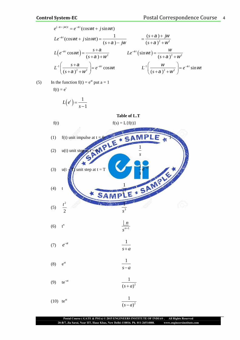
Table of L.T
f(t) f(s) = L{f(t)}
(1) f(t) unit impulse at t = 0 1
(2) u(t) unit step at t = 01
s
(3) u(t – T) unit step at t = T1 sTes
(4) t 2
1
s
(5)2
2
t3
1
s
(6) tn1n
n
s
(7) ate1
s a
(8) eat 1
s a
(9) te–at2
1
( )s a
(10) teat2
1
( )s a
Page 5
Control System-EC Postal Correspondence Course 5
Postal Course ( GATE & PSUs) © 2015 ENGINEERS INSTITUTE OF INDIA® . All Rights Reserved28-B/7, Jia Sarai, Near IIT, Hauz Khas, New Delhi-110016. Ph. 011-26514888. www.engineersinstitute.com
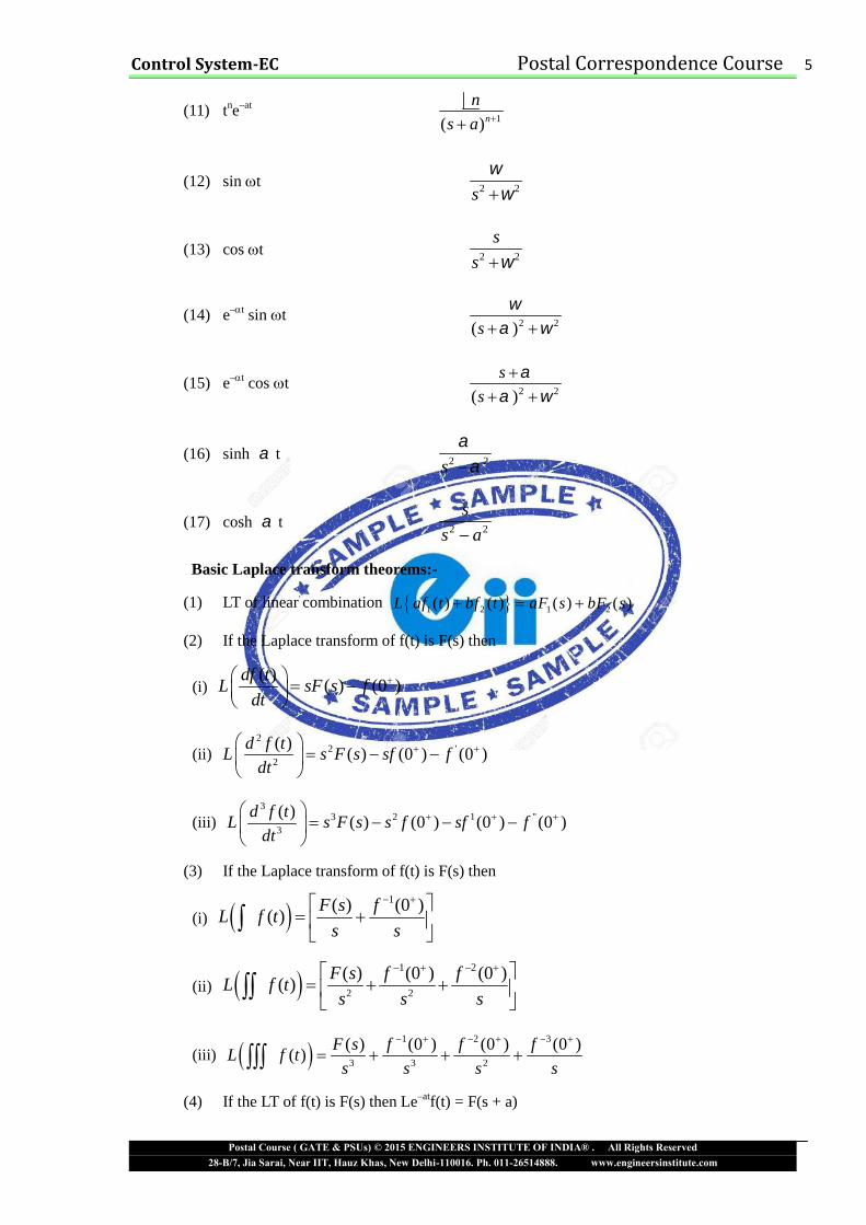
(11) tne–at1( )n
n
s a
(12) sin t 2 2s
(13) cos t 2 2
s
s
(14) e–t sin t2 2( )s
(15) e–t cos t2 2( )
s
s
(16) sinh t 2 2s
(17) cosh t 2 2
s
s a
Basic Laplace transform theorems:-
(1) LT of linear combination 1 2 1 2( ) ( ) ( ) ( )L af t bf t aF s bF s
(2) If the Laplace transform of f(t) is F(s) then
(i)( )
( ) (0 )df t
L sF s fdt
(ii)2
2 '2
( )( ) (0 ) (0 )
d f tL s F s sf f
dt
(iii)3
3 2 1 "3
( )( ) (0 ) (0 ) (0 )
d f tL s F s s f sf f
dt
(3) If the Laplace transform of f(t) is F(s) then
(i) 1( ) (0 )
( )F s f
L f ts s
(ii) 1 2
2 2
( ) (0 ) (0 )( )
F s f fL f t
s s s
(iii) 1 2 3
3 3 2
( ) (0 ) (0 ) (0 )( )
F s f f fL f t
s s s s
(4) If the LT of f(t) is F(s) then Le–atf(t) = F(s + a)
Page 6
Control System-EC Postal Correspondence Course 6
Postal Course ( GATE & PSUs) © 2015 ENGINEERS INSTITUTE OF INDIA® . All Rights Reserved28-B/7, Jia Sarai, Near IIT, Hauz Khas, New Delhi-110016. Ph. 011-26514888. www.engineersinstitute.com
(5) if the LT of f(t) is F(s)
( )( )
dF sL tf t
ds
(6) Initial value theorem
0 0lim ( ) lim ( ) lim ( ) lim ( )t s t s
f t s Lf t f t sF s
(7)0 0
lim ( ) lim ( ) lim ( ) lim ( )t s t s
f t sLf t f t sF s
Q.1. Find the invercese LT of the following functions
(i)1
( )( 1)
F ss s
1 1 1
1
1 1 1
( 1) 1
1(1 )
( 1)t
L L Ls s s s
L es s
(ii)2
6 6
( 4 3) ( 1)( 3)
s s
s s s s s s
1 1
3
12 2.5 2( )
1 3
( ) 2 2.5 .5t t
L F s Ls s s
f t e e
Q.2. Use the Laplace transform to solve the differential equation
2
2
( ) ( )6 8 ( ) 2 ( )
( ) 1, '(0) 2
d v t dv tv t u t
dt dtv o v
Solution : We take the L.T of each term in given differential equation
2
2
2( ) (0) '(0) 6 ( ) (0) 8 ( )
(0) 1, '(0) 2
2( ) 2 6 ( ) 1 8 ( )
s V s sV V sV s V V sS
V V
s V s s sV s V ss
2
0 2 4
4 2( )
( 2)( 4) 2 4
1 1 1( ) / ( 2) ( ) / ( 4) ( ) /
4 2 4s s s
s s A B CV s
s s s s s s
A sV s B s V s C s V s
Page 7
Control System-EC Postal Correspondence Course 7
Postal Course ( GATE & PSUs) © 2015 ENGINEERS INSTITUTE OF INDIA® . All Rights Reserved28-B/7, Jia Sarai, Near IIT, Hauz Khas, New Delhi-110016. Ph. 011-26514888. www.engineersinstitute.com
1 1 14 2 4( )
2 4V s
s s s
by the Inverse L.T
2 41( ) (1 2 ) ( )
4t tV t e e u t
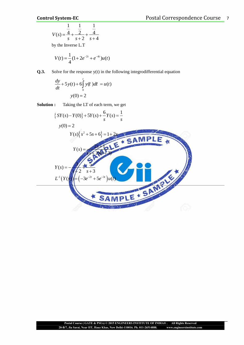
Q.3. Solve for the response y(t) in the following integrodifferential equation
0
5 ( ) 6 ( ) ( )
(0) 2
tdyy t y d u t
dt
y
Solution : Taking the LT of each term, we get
2
6 1( ) (0) 5 ( ) ( )
(0) 2
( ) 5 6 1 2
SY s Y Y s Y ss s
y
Y s s s s
2 1( )
( 2)( 3)
sY s
s s
1 2 3
3 5( )
2 3
( ) 3 5 ( )t t
Y ss s
L Y s e e u t
Page 8
Control System-EC Postal Correspondence Course 8
Postal Course ( GATE & PSUs) © 2015 ENGINEERS INSTITUTE OF INDIA® . All Rights Reserved28-B/7, Jia Sarai, Near IIT, Hauz Khas, New Delhi-110016. Ph. 011-26514888. www.engineersinstitute.com
CHAPTER-2
BASICS OF CONTROL SYSTEM
Open–Loop Control System
ControlInput Output
Action
In an open loop Control System the output is neither measured nor feedback for comparison with input.
Faithfulness of an open loop control system depends on the accuracy of input calibration.
Closed-Loop Control System
In a closed loop control system the output has an effect on control action through a feedback as shown
figure and hence closed loop control systems are also termed as feedback control systems. The control
action is actuated by an error signal e which is the difference b/w the input signal r and the output
signal c. This process of comparison b/w the output and input maintains the output at a desired level
through control action process.
Open Loop Systems
( ). . ( )
( )
C sT F G s
R s
Closed Loop Systems
Figure-(a)
1. Automatic coffee server 1. Electric Iron
2. Traffic Signal 2. D.C motor speed control
ADVANTAGES
3. Simple and economic 3. Accurate and reliable
Disadvantages
4. Unreliable 4. The system is complex and costly
Page 9
Control System-EC Postal Correspondence Course 9
Postal Course ( GATE & PSUs) © 2015 ENGINEERS INSTITUTE OF INDIA® . All Rights Reserved28-B/7, Jia Sarai, Near IIT, Hauz Khas, New Delhi-110016. Ph. 011-26514888. www.engineersinstitute.com
5. Inaccurate 5. System may become unstable
From Figure-(a)
( ) ( ). ( )C s G s E s …..(i)( ) ( ) ( )E s R s B s …..(ii)( ) ( ) ( )B s C s H s …..(iii)
From (ii) and (iii) we have
( ) ( ) ( ). ( )E s R s C s H s …..(iv)
From (i) and (iv) we have
( )( ) ( ). ( )
( )
C sR s C s H s
G s 1 ( ) ( )
( ) ( )( )
G s H sR s C s
G s
( ) ( )
( ) 1 ( ) ( )
C s G s
R s G s H s
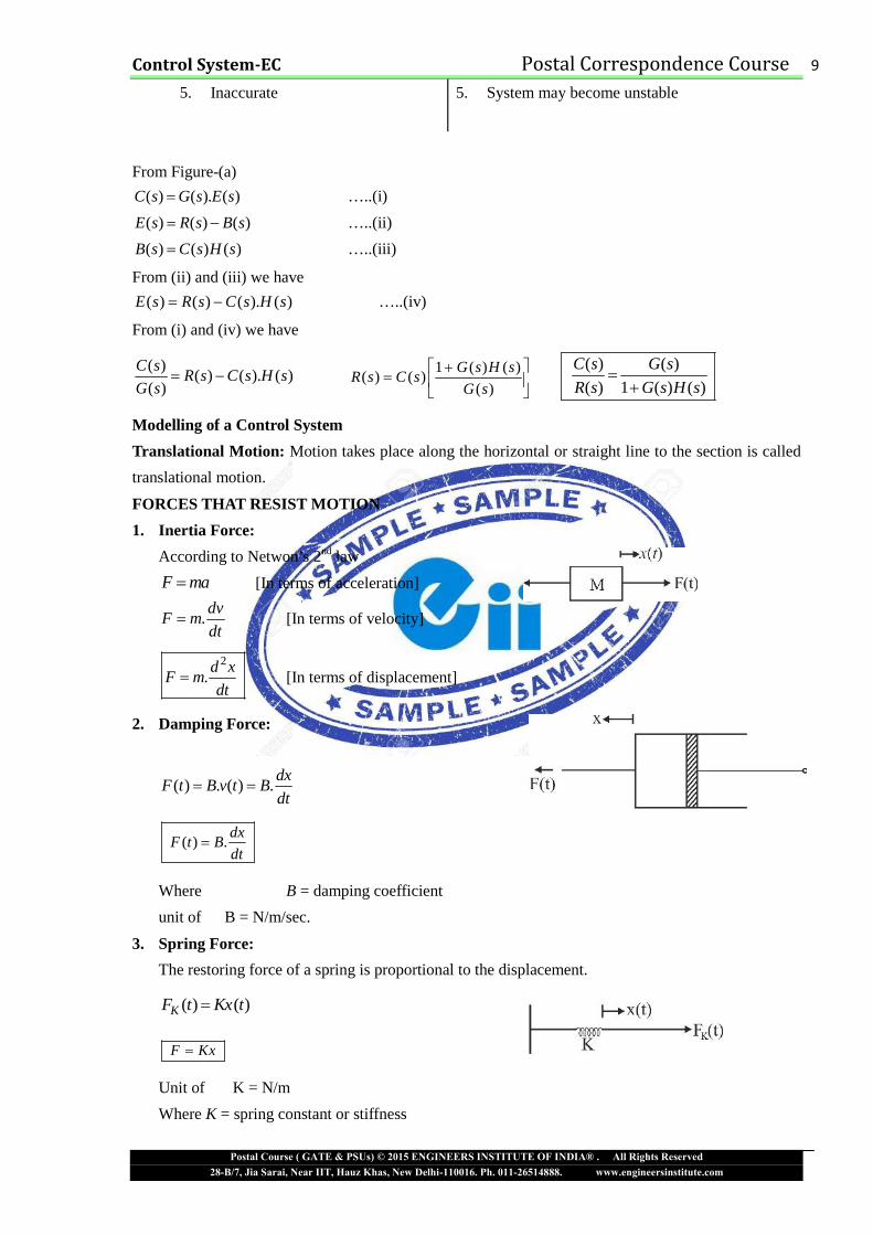
Modelling of a Control System
Translational Motion: Motion takes place along the horizontal or straight line to the section is called
translational motion.
FORCES THAT RESIST MOTION
1. Inertia Force:
According to Netwon’s 2nd law
F ma [In terms of acceleration]
.dv
F mdt
[In terms of velocity]
2
.d x
F mdt
[In terms of displacement]
2. Damping Force:
( ) . ( ) .dx
F t B v t Bdt
( ) .dx
F t Bdt
Where B = damping coefficient
unit of B = N/m/sec.
3. Spring Force:
The restoring force of a spring is proportional to the displacement.
( ) ( )KF t Kx t
F Kx
Unit of K = N/m
Where K = spring constant or stiffness
Page 10
Control System-EC Postal Correspondence Course 10
Postal Course ( GATE & PSUs) © 2015 ENGINEERS INSTITUTE OF INDIA® . All Rights Reserved28-B/7, Jia Sarai, Near IIT, Hauz Khas, New Delhi-110016. Ph. 011-26514888. www.engineersinstitute.com
Stiffness = Restoring force per unit displacement.
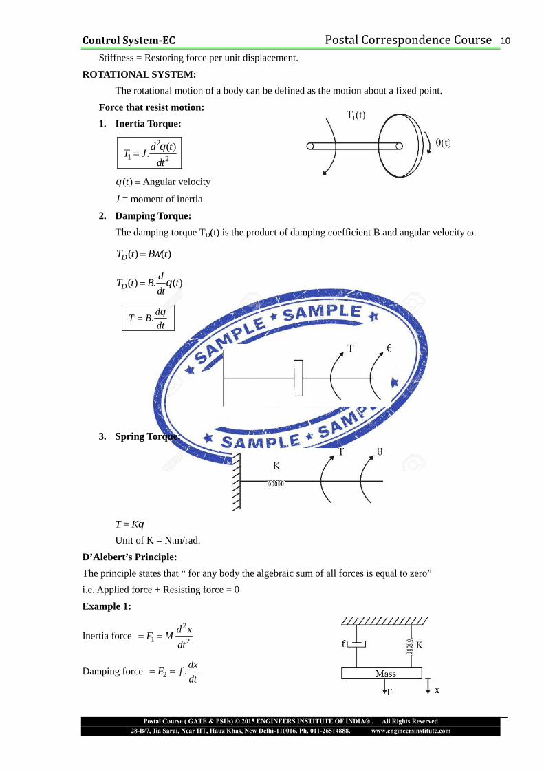
ROTATIONAL SYSTEM:
The rotational motion of a body can be defined as the motion about a fixed point.
Force that resist motion:
1. Inertia Torque:
2
1 2
( ).d t
T Jdt
( )t Angular velocity
J = moment of inertia
2. Damping Torque:
The damping torque TD(t) is the product of damping coefficient B and angular velocity .
( ) ( )DT t B t
( ) . ( )Dd
T t B tdt
.d
T Bdt
3. Spring Torque:
T = K
Unit of K = N.m/rad.
D’Alebert’s Principle:The principle states that “ for any body the algebraic sum of all forces is equal to zero”i.e. Applied force + Resisting force = 0
Example 1:
Inertia force2
1 2
d xF M
dt
Damping force 2 .dx
F fdt
Page 11
Control System-EC Postal Correspondence Course 11
Postal Course ( GATE & PSUs) © 2015 ENGINEERS INSTITUTE OF INDIA® . All Rights Reserved28-B/7, Jia Sarai, Near IIT, Hauz Khas, New Delhi-110016. Ph. 011-26514888. www.engineersinstitute.com
Spring force 3F Kx
From D’Alembert’s principal
1 2 3F F F F
2
2...(1)
d x dxF M f kx
dtdt
i.e. Applied force = Resisting force.
Procedure of Writing the Equations for Mechanical Systems:
1. Consider the system is in equilibrium
2. Same arbitrary displacement
3. Draw a free body diagram for each mass.
4. Apply Newton’s law of motion on each diagram
5. Write the equation in suitable form
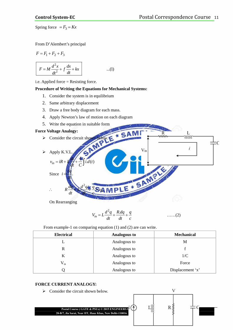
Force Voltage Analogy:
Consider the circuit shown below.
Apply K.V.L.
1. ( )in
div iR L i d t
dt C
Since .dq
idt
2
indq d q q
R L vdt dt c
On Rearranging
2 .in
d q R dq qV L
dt dt c ……(2)
From example-1 on comparing equation (1) and (2) are can write.
Electrical Analogous to Mechanical
L
R
K
Vin
Q
Analogous to
Analogous to
Analogous to
Analogous to
Analogous to
M
f
1/C
Force
Displacement ‘x’
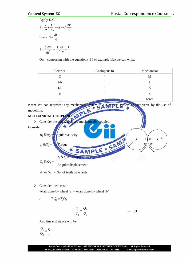
FORCE CURRENT ANALOGY:
Consider the circuit shown below.
Page 12
Control System-EC Postal Correspondence Course 12
Postal Course ( GATE & PSUs) © 2015 ENGINEERS INSTITUTE OF INDIA® . All Rights Reserved28-B/7, Jia Sarai, Near IIT, Hauz Khas, New Delhi-110016. Ph. 011-26514888. www.engineersinstitute.com
Apply K.C.L.
1. .
V dVi v dt C
R L dt
Sinced
vdt
2
2
1.
Cd di
R dt Ldt
On comparing with the equation ( 1 ) of example 1(a) we can write.
Electrical Analogous to Mechanical
C
1/R
1/L
I
“““““
M
f
K
x
force
Note: We can represent any mechanical system to a electrical system or vice-versa by the use of
modelling.
MECHANICAL COUPLING:
Consider the two wheels are mechanically coupled.
Consider
1 2&w w Angular velocity
1 2&T T Torque
1 2&r r Radius
Angular displacement
1 2&N N = No. of teeth on wheels
Consider ideal case
Work done by wheel ‘a’ = work done by wheel ‘b’
1 1 2 2T Q T Q
1 2
2 1
T Q
T Q ……(i)
And linear distance will be
1 2
2 1
Q r
Q r
1 2&Q Q
Page 13
Control System-EC Postal Correspondence Course 13
Postal Course ( GATE & PSUs) © 2015 ENGINEERS INSTITUTE OF INDIA® . All Rights Reserved28-B/7, Jia Sarai, Near IIT, Hauz Khas, New Delhi-110016. Ph. 011-26514888. www.engineersinstitute.com
1 2 1
2 1 2
T Q r
T Q r …..(ii)
Since the n.o. of teeth is proportional to radius. Thus
1 1
2 2
N r
N r
And 1 2
2 1
w Q
w Q
So 1 2 1 1 2
2 1 2 2 1
T Q r N w
T Q r N w …..(iii)
From force-voltage analogy
Where
V1 is analogous to T1
V2 is analogous to T2
I1 is analogous to w1
I2 is analogous to w2
r1 is analogous to N1
r2 is analogous to N2
From force-current analogy
Question: Show the electrical connection diagram and model the armature controlled d.c. motor in a
block diagram form. Assume the necessary variables and obtained transfer function for change in
position of armature to the change in armature voltage. Express the transfer function in standard form.
IES-2011-EE
Solutions: Armature Controlled d.c. Motor
Page 14
Control System-EC Postal Correspondence Course 14
Postal Course ( GATE & PSUs) © 2015 ENGINEERS INSTITUTE OF INDIA® . All Rights Reserved28-B/7, Jia Sarai, Near IIT, Hauz Khas, New Delhi-110016. Ph. 011-26514888. www.engineersinstitute.com
Figure
Consider the armature controlled d.c. motor and assume that the demagnetizing effect of
armature reaction is neglected, magnetic circuit is assumed linear and field voltage is constant i.e.
If = constant
Let aR Armature resistance
aL Armature self inductance caused by armature flux
if = field current
E = Induced e.m.f in armature
V = Applied voltage
T = Torque developed by the motor
= Angular displacement of the motor shaft
J = Equivalent moment of inertia of motor shaft & load referred to the motor
B = equivalent coefficient of friction of motor and load referred to the motor
Apply KVL in armature circuit
aa a
diV R i L E
dt …..(1)
Since, field current If Constant, the flux will be constant
When armature is rotating, an e.m.f is induced
E
bE K
or , bd
E Kdt
…..(2)
Where angular velocity
bK Back e.m.f constant
Now, the torque T delivered by the motor will be the product of armature current and flux
aT i
aT K i …..(3)
Where K = motor torque constant
The dynamic equation with moment of inertia & coefficient of friction will be
2
2
d dT J B
dtdt
…..(4)
Take the Laplace transform of equations 1, 2, 3 and 4
( ) ( ) ( )( )a a aV s E s I s R SL
( ) ( )bE s K S s
Page 15
Control System-EC Postal Correspondence Course 15
Postal Course ( GATE & PSUs) © 2015 ENGINEERS INSTITUTE OF INDIA® . All Rights Reserved28-B/7, Jia Sarai, Near IIT, Hauz Khas, New Delhi-110016. Ph. 011-26514888. www.engineersinstitute.com
( ) ( )aT s K I s
2( ) ( ) ( )T s s J sB s
( ) ( ) ( )T s SJ B S s
The block diagram for each equation
Combine all four block diagrams
Figure : Block diagram of armature controlled d.c. motor
Now determine the transfer function by block reduction method.
( )
( ) ( )( )a a b
s K
V s R sL Js B s KK s
….(5)
Equation 5 can be written as
( )
( )1 1 .a
a ba
s K
V s L JR s sB s KK s
R B
Put aa
a
L
R time constant of armature circuit
mJ
B Mechanical time constant
Equation 5 becomes
Page 16
Control System-EC Postal Correspondence Course 16
Postal Course ( GATE & PSUs) © 2015 ENGINEERS INSTITUTE OF INDIA® . All Rights Reserved28-B/7, Jia Sarai, Near IIT, Hauz Khas, New Delhi-110016. Ph. 011-26514888. www.engineersinstitute.com
( )
( ) (1 )(1 )a a m b
s K
V s sR B s s KK s
…..(6)
From the block diag. figure it is clear that it is a closed loop system. The effect of the back e.m.f is
represented by the feedback signal proportional to the speed of the motor.
77 Final Selections in Engineering Services 2014.Rank Roll Name Branch
1 171298 SAHIL GARG EE3 131400 FIRDAUS KHAN ECE6 088542 SUNEET KUMAR TOMAR ECE8 024248 DEEPANSHU SINGH EE
10 207735 VASU HANDA ECE22 005386 RAN SINGH GODARA ECE22 032483 PAWAN KUMAR EE29 070313 SAURABH GOYAL EE31 214577 PRAMOD RAWANI EE33 075338 DIPTI RANJAN TRIPATHY ECE35 003853 SHANKAR GANESH K ECE35 091781 KOUSHIK PAN EE36 052187 ANOOP A ECE37 008233 ARPIT SHUKLA ECE38 106114 MANISH GUPTA EE41 018349 VINAY GUPTA ECE44 098058 LEENA P MARKOSE EE45 029174 NAVNEET KUMAR KANWAT EE
9 Rank under AIR 100 in GATE 2015 ( Rank 6,8,19,28,41,56,76,91,98)
and many more.............................
To Buy Postal Correspondence Package call at 0-9990657855