2 THE OP7 SYSTEM ..................................................................................................................................... 32.1 DESCRIPTION ................................................................................................................................. 32.2 KEY FUNCTIONS ............................................................................................................................ 42.3 BRIEF LIST OF THE MOST USED TERMINOLOGY............................................................................... 52.4 START-UP ....................................................................................................................................... 6
2.4.1 HOW TO SWITCH ON/OFF .................................................................................................. 72.5 HOW TO THE SET SOFTWARE ALARMS .......................................................................................... 72.6 OPERATION DIAGRAM .................................................................................................................. 8
3 MANUAL OPERATION ............................................................................................................................. 93.1 HOW TO SET A VALUE .................................................................................................................. 9
TEST START-UP ............................................................................................................................. 113.2 HOW TO SET A CONTROLLED SLOPE ........................................................................................... 12
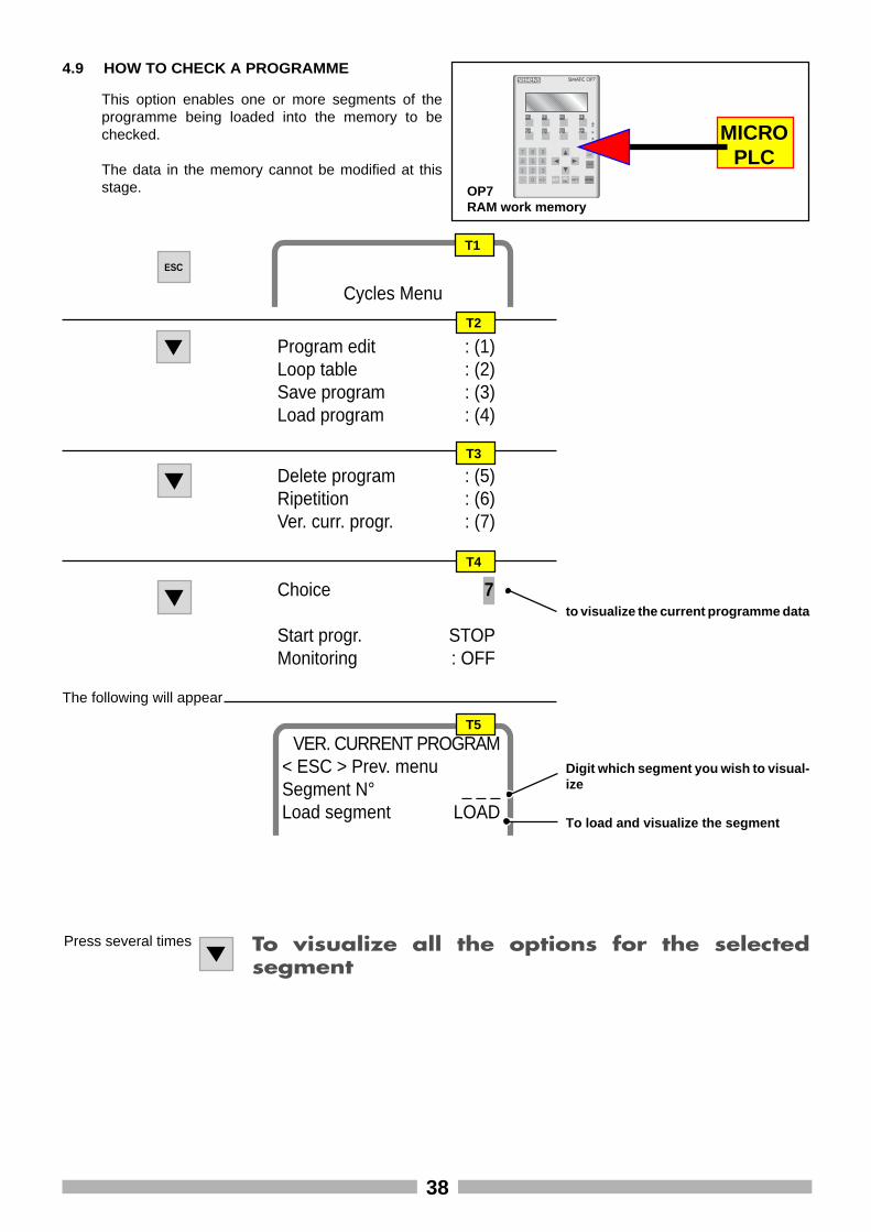
4 AUTOMATIC OPERATION ...................................................................................................................... 184.1 EXAMPLE CYCLE ........................................................................................................................... 184.2 EXAMPLE CYCLE TABLE ................................................................................................................. 194.3 HOW TO SET A PROGRAMME ..................................................................................................... 204.4 LOOP TABLE ................................................................................................................................. 334.5 HOW TO SAVE A PROGRAMME .................................................................................................. 344.6 HOW TO LOAD AND CARRY OUT A PROGRAMME ...................................................................... 354.7 HOW TO DELETE A PROGRAMME ................................................................................................ 364.8 REPETITONS (HOW TO REPEAT A PROGRAMME) .......................................................................... 374.9 HOW TO CHECK A PROGRAMME ................................................................................................ 384.10 HOW TO VISUALIZE A PROGRAMME ........................................................................................... 394.11 HOW TO VISUALIZE USER ANALOG INPUTS ................................................................................ 414.12 HOW TO VISUALIZE USER PT100.................................................................................................. 41
5 GENERAL SETTINGS ............................................................................................................................... 425.1 USER ANALOG INPUT CONFIGURATION (FROM 1 TO 6) ................................................................. 42
• The machine must only be used as described in this hand-book.
• The machine must only be used by personnel who have readall the instructions contained in this handbook.
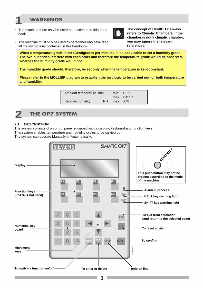
2.1 DESCRIPTIONThe system consists of a control panel equipped with a display, keyboard and function keys.This system enables temperature and humidity cycles to be carried out.The system can operate Manually or Automatically.
2 THE OP7 SYSTEM
The concept of HUMIDITY alwaysrefers to Climatic Chambers. If thechamber is not a climatic chamber,you may ignore the relevantreferences.
1 WARNINGS
Numerical key-board
Display
Function keys(F2-F3-F4 not used)
To confirm
Movementkeys
To reset an alarm
To exit from a function(and return to the selected page)
This push-button may not bepresent according to the modelof the machine
When a temperature grade is set (Centigrades per minute), it is unadvisable to set a humidity grade.The two quantities interfere with each other and therefore the temperature grade would be observed,whereas the humidity grade would not.
The humidity grade should, therefore, be set only when the temperature is kept constant.
Please refer to the MOLLIER diagram to establish the test logic to be carried out for both temperatureand humidity.
Ambient temperature min: min: + 5°Cmax + 45°C
Relative humidity RH max 80%
To enter or delete Help on line
SHIFT key warning light
HELP key warning light
START/STOP
Alarm in process
4
SIEMENS SIMATIC OP7
F1 F2 F3 F4
K1 K2 K3 K4
7 8 9
4 5 6
1 2 3. 0 +/- SHIFT
INSDEL
HELP ENTER
ACK
ESC
HELP
SHIFT MICROPLC
OP7RAM work memory (volatile)
Main memory
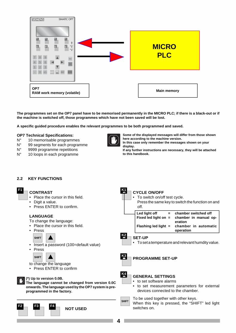
The programmes set on the OP7 panel have to be memorised permanently in the MICRO PLC; if there is a black-out or ifthe machine is switched off, those programmes which have not been saved will be lost.
A specific guided procedure enables the relevant programmes to be both programmed and saved.
OP7 Technical Specifications:N° 10 memorisable programmesN° 99 segments for each programmeN° 9999 programme repetitionsN° 10 loops in each programme
Some of the displayed messages will differ from those shownhere according to the machine version.In this case only remember the messages shown on yourdisplay.If any further instructions are necessary, they will be attachedto this handbook.
F1CONTRAST• Place the cursor in this field.• Digit a value.• Press ENTER to confirm.
LANGUAGETo change the language:• Place the cursor in this field.• Press
• Insert a password (100=default value)• Press
to change the language• Press ENTER to confirm
F2 F3 F4NOT USED
K1CYCLE ON/OFF• To switch on/off test cycle.
Press the same key to switch the function on andoff.
SHIFT
SHIFT
Led light off = chamber switched offFixed led light on = chamber in manual op-
erationFlashing led light = chamber in automatic
operation
2.2 KEY FUNCTIONS
K2SET-UP• To set a temperature and relevant humdity value.
K3PROGRAMME SET-UP
K4GENERAL SETTINGS• to set software alarms• to set measurement parameters for external
devices connected to the chamber.
SHIFTTo be used together with other keys.When this key is pressed, the “SHIFT” led lightswitches on.
(*) Up to version 0.0B.The language cannot be changed from version 0.0Conwards. The language used by the OP7 system is pre-programmed in the factory.
5
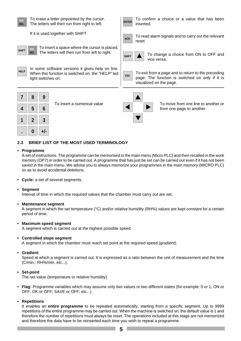
To move from one line to another orfrom one page to another
ENTERTo confirm a choice or a value that has beeninserted.
To insert a numerical value
SHIFT To change a choice from ON to OFF andvice versa.
INSDEL
To erase a letter pinpointed by the cursor.The letters will then run from right to left.
If it is used together with SHIFT
SHIFT INSDEL
To insert a space where the cursor is placed.The letters will then run from left to right.
HELPIn some software versions it gives help on line.When this function is switched on, the “HELP” ledlight switches on.
ACKTo read alarm signals and to carry out the relevantreset.
ESCTo exit from a page and to return to the precedingpage. The function is switched on only if it isvisualized on the page.
0. +/-
21 3
54 6
87 9
2.3 BRIEF LIST OF THE MOST USED TERMINOLOGY
• ProgrammeA set of instructions. The programme can be memorised in the main menu (Micro PLC) and then recalled in the workmemory (OP7) in order to be carried out. A programme that has just be set can be carried out even if it has not beensaved in the main menu. We advise you to always memorize your programmes in the main memory (MICRO PLC)so as to avoid accidental deletions.
• Cycle: a set of several segments.
• SegmentInterval of time in which the required values that the chamber must carry out are set.
• Maintenance segmentA segment in which the set temperature (°C) and/or relative humidity (RH%) values are kept constant for a certainperiod of time.
• Maximum speed segmentA segment which is carried out at the highest possible speed.
• Controlled slope segmentA segment in which the chamber must reach set point at the required speed (gradient).
• GradientSpeed at which a segment is carried out. It is expressed as a ratio between the unit of measurement and the time(C/min.; RH%/min. etc...).
• Set-pointThe set value (temperature or relative humidity).
• Flag: Programme variables which may assume only two values or two different states (for example: 0 or 1; ON orOFF; OK or OFF; SAVE or OFF; etc...)
• RepetitionsIt enables an entire programme to be repeated automatically, starting from a specific segment. Up to 9999repetitions of the entire programme may be carried out. When the machine is switched on, the default value is 1 andtherefore the number of repetitions must always be reset. The operations included at this stage are not memorizedand therefore the data have to be reinserted each time you wish to repeat a programme.
6
• Loop tableThis enables up to 10 repetitions of parts of a programme (series of segments or single segment) to be set. It ispossible to carry out another nested loop within a loop; the former, however, must be part of the main loop.
• Special and/or auxiliary contactsTo electrically switch on certain characteristic functions of the system as well as auxiliary contacts (externalapparatus).
• How to load a programmeProcedure to load a programme (already saved in the main memory) into the work memory (OP7). This procedureis always carried out before executing a programme.
• How to save a programmeTo memorize a programme permanently in the system’s main memory (Micro PLC).
• Channel 1Temperature channel.
• Channel 2Relative humidity channel.
• Duration waitON: the segment is considered finished only when the set time has passed. After this period of time the programmemoves on to the following segment, indipendently of the set temperature or humidity value.OFF: the segment is considered finished when the set time finishes, whether the set point has been reached or not.NB: The “Duration wait” and “Setpoint wait” flags must not both be turned OFF at the same time.
• Control SystemON: the relevant channel (temperature, humidity, etc..) is controlledOFF: the relevant channel (temperature, humidity, etc...) is not controlled
• Wait set-pointON: the segment is considered terminated only when the pre-set set-point value (temperature or relative humidity)has been reached; the programme then moves on to the next segment.OFF: the segment is considered terminated at the end of the pre-set time, whether the set-point has been reachedor not.NB: The "Wait duration" and "Wait set-point" flags should never both be switched off at the same time.
• Maximum speedON: the set value (SET POINT) is reached at the highest possible speed.OFF: the programme considers the set gradient.
• Near setThe tolerance within which the set point is considered to have been reached.A default value is memorized; this value should not be changed.In order for this indication to be effective while the programme is being carried out, the “Wait set-point” flag must beswitched on (ON).
• CTRL humid. spec.ON/OFF: this option has been introduced in order to improve the performance of the system under certain workconditions. On the basis of the results obtained during a cycle, the user may experiment by changing this flag to seewhether the chamber performance improves or not.
2.4 START-UP
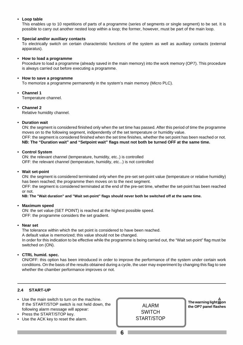
• Use the main switch to turn on the machine.If the START/STOP switch is not held down, thefollowing alarm message will appear:
• Press the START/STOP key.• Use the ACK key to reset the alarm.
ALARMSWITCH
START/STOP
The warning light onthe OP7 panel flashes
7
When the system is switched on, it checks all theparameters and visualizes page P1.The page visualized by the system may vary accordingto the version of the chamber.
Angelantoni Ind.Challenge 0.000
P1
Version ofthe residentprogramme
B)By pressing the lighted START/STOP push-button When this push-button is pressed, the machinestops and restarts either manually or automatically.(This push butom may not be present according tothe version of the machine).
C)By switching off the main switch (isolating switch) The machine is switched off.When it is switched on again:- in MANUAL mode a cycle has to be reprogrammed andrestarted as the data will have been lost.- in AUTOMATIC mode the cycle may be recalled and restarted.
The instructions to start up the cycles ineither MANUAL or AUTOMATIC modewill be given in the following chapters.
START/STOP
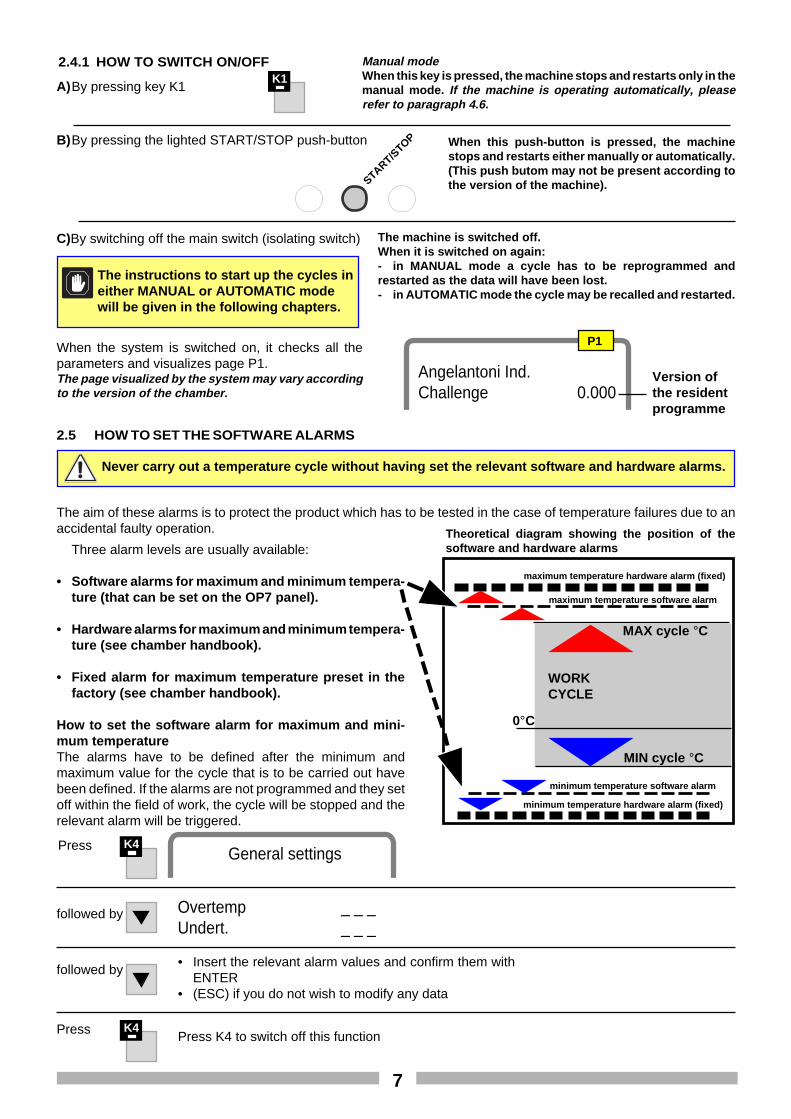
2.5 HOW TO SET THE SOFTWARE ALARMS
Never carry out a temperature cycle without having set the relevant software and hardware alarms.
Three alarm levels are usually available:
• Software alarms for maximum and minimum tempera-ture (that can be set on the OP7 panel).
• Hardware alarms for maximum and minimum tempera-ture (see chamber handbook).
• Fixed alarm for maximum temperature preset in thefactory (see chamber handbook).
How to set the software alarm for maximum and mini-mum temperatureThe alarms have to be defined after the minimum andmaximum value for the cycle that is to be carried out havebeen defined. If the alarms are not programmed and they setoff within the field of work, the cycle will be stopped and therelevant alarm will be triggered.
Theoretical diagram showing the position of thesoftware and hardware alarms
0°C
MIN cycle °C
maximum temperature software alarm
WORKCYCLE
maximum temperature hardware alarm (fixed)
MAX cycle °C
The aim of these alarms is to protect the product which has to be tested in the case of temperature failures due to anaccidental faulty operation.
minimum temperature software alarm
minimum temperature hardware alarm (fixed)
followed by• Insert the relevant alarm values and confirm them with
ENTER• (ESC) if you do not wish to modify any data
K4Press Press K4 to switch off this function
K1Manual modeWhen this key is pressed, the machine stops and restarts only in themanual mode. If the machine is operating automatically, pleaserefer to paragraph 4.6.
A)By pressing key K1
2.4.1 HOW TO SWITCH ON/OFF
followed by Overtemp _ _ _Undert. _ _ _
K4Press General settings
8
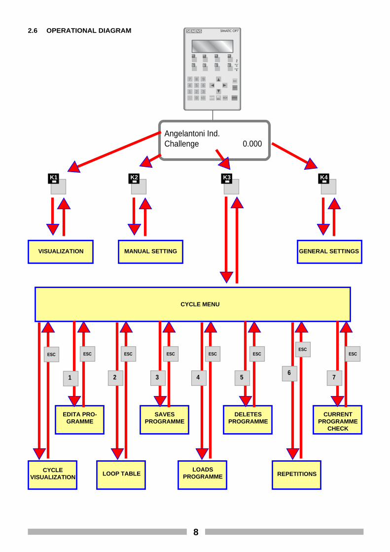
REPETITIONS
CURRENTPROGRAMME
CHECK
DELETESPROGRAMME
SAVESPROGRAMME
EDITA PRO-GRAMME
2.6 OPERATIONAL DIAGRAM SIEMENS SIMATIC OP7
F1 F2 F3 F4
K1 K2 K3 K4
7 8 9
4 5 6
1 2 3. 0 +/- SHIFT
INSDEL
HELP ENTER
ACK
ESC
HELP
SHIFT
Angelantoni Ind.Challenge 0.000
K1 K2 K3 K4
VISUALIZATION MANUAL SETTING GENERAL SETTINGS
CYCLE MENU
CYCLEVISUALIZATION
ESC ESC ESC ESC ESC ESCESC
ESC
LOOP TABLE
1 2 3 4 56
7
LOADSPROGRAMME
9
3 MANUAL OPERATION
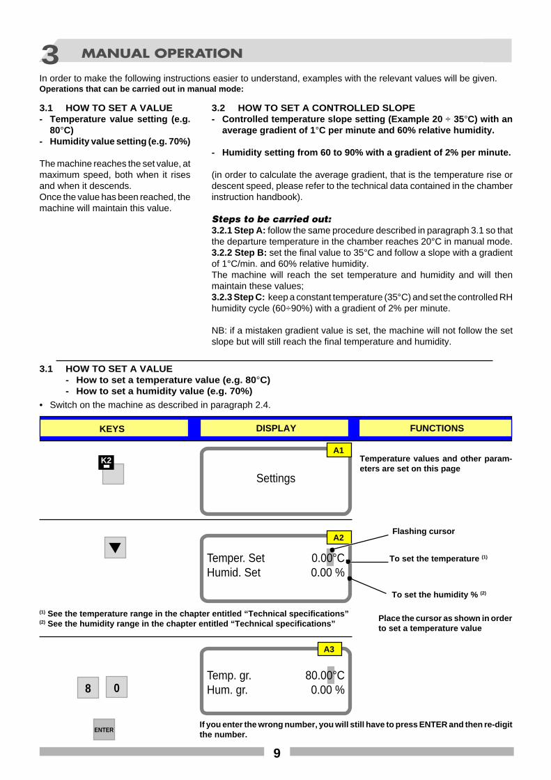
3.1 HOW TO SET A VALUE- Temperature value setting (e.g.
80°C)- Humidity value setting (e.g. 70%)
The machine reaches the set value, atmaximum speed, both when it risesand when it descends.Once the value has been reached, themachine will maintain this value.
3.1 HOW TO SET A VALUE- How to set a temperature value (e.g. 80 °C)- How to set a humidity value (e.g. 70%)
K2
Settings
A1
Temper. Set 0.00°CHumid. Set 0.00 %
A2Flashing cursor
To set the humidity % (2)
(1) See the temperature range in the chapter entitled “Technical specifications”(2) See the humidity range in the chapter entitled “Technical specifications”
Temperature values and other param-eters are set on this page
In order to make the following instructions easier to understand, examples with the relevant values will be given.Operations that can be carried out in manual mode:
3.2 HOW TO SET A CONTROLLED SLOPE- Controlled temperature slope setting (Example 20 ÷ 35°C) with an
average gradient of 1 °C per minute and 60% relative humidity.
- Humidity setting from 60 to 90% with a gradient of 2% per minute.
(in order to calculate the average gradient, that is the temperature rise ordescent speed, please refer to the technical data contained in the chamberinstruction handbook).
Steps to be carried out:3.2.1 Step A: follow the same procedure described in paragraph 3.1 so thatthe departure temperature in the chamber reaches 20°C in manual mode.3.2.2 Step B: set the final value to 35°C and follow a slope with a gradientof 1°C/min. and 60% relative humidity.The machine will reach the set temperature and humidity and will thenmaintain these values;3.2.3 Step C: keep a constant temperature (35°C) and set the controlled RHhumidity cycle (60÷90%) with a gradient of 2% per minute.
NB: if a mistaken gradient value is set, the machine will not follow the setslope but will still reach the final temperature and humidity.
A3
Place the cursor as shown in orderto set a temperature value
Temp. gr. 80.00°CHum. gr. 0.00 %8 0
ENTERIf you enter the wrong number, you will still have to press ENTER and then re-digitthe number.
To set the temperature (1)
KEYS DISPLAY FUNCTIONS
• Switch on the machine as described in paragraph 2.4.
10
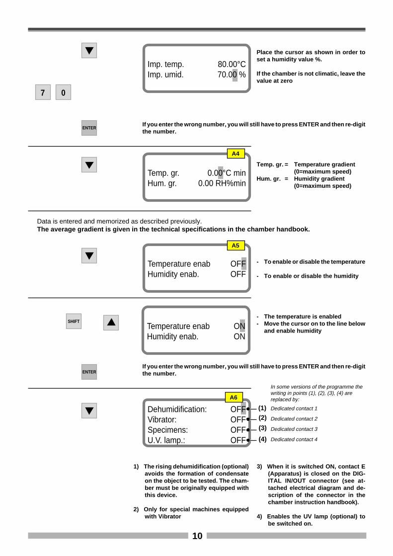
7 0
Imp. temp. 80.00°CImp. umid. 70.00 %
ENTERIf you enter the wrong number, you will still have to press ENTER and then re-digitthe number.
Temp. gr. 0.00°C minHum. gr. 0.00 RH%min
Temp. gr. = Temperature gradient(0=maximum speed)
Hum. gr. = Humidity gradient(0=maximum speed)
SHIFT
Temperature enab OFFHumidity enab. OFF
- To enable or disable the temperature
- To enable or disable the humidity
Data is entered and memorized as described previously.The average gradient is given in the technical specifications in the chamber handbook.
Temperature enab ONHumidity enab. ON
- The temperature is enabled- Move the cursor on to the line below
and enable humidity
ENTERIf you enter the wrong number, you will still have to press ENTER and then re-digitthe number.
Place the cursor as shown in order toset a humidity value %.
If the chamber is not climatic, leave thevalue at zero
A4
A5
Dehumidification: OFFVibrator: OFFSpecimens: OFFU.V. lamp.: OFF
(1)(2)
(3)
(4)
1) The rising dehumidification (optional)avoids the formation of condensateon the object to be tested. The cham-ber must be originally equipped withthis device.
2) Only for special machines equippedwith Vibrator
3) When it is switched ON, contact E(Apparatus) is closed on the DIG-ITAL IN/OUT connector (see at-tached electrical diagram and de-scription of the connector in thechamber instruction handbook).
4) Enables the UV lamp (optional) tobe switched on.
A6
In some versions of the programme thewriting in points (1), (2), (3), (4) arereplaced by:
Dedicated contact 1
Dedicated contact 2
Dedicated contact 3
Dedicated contact 4
11
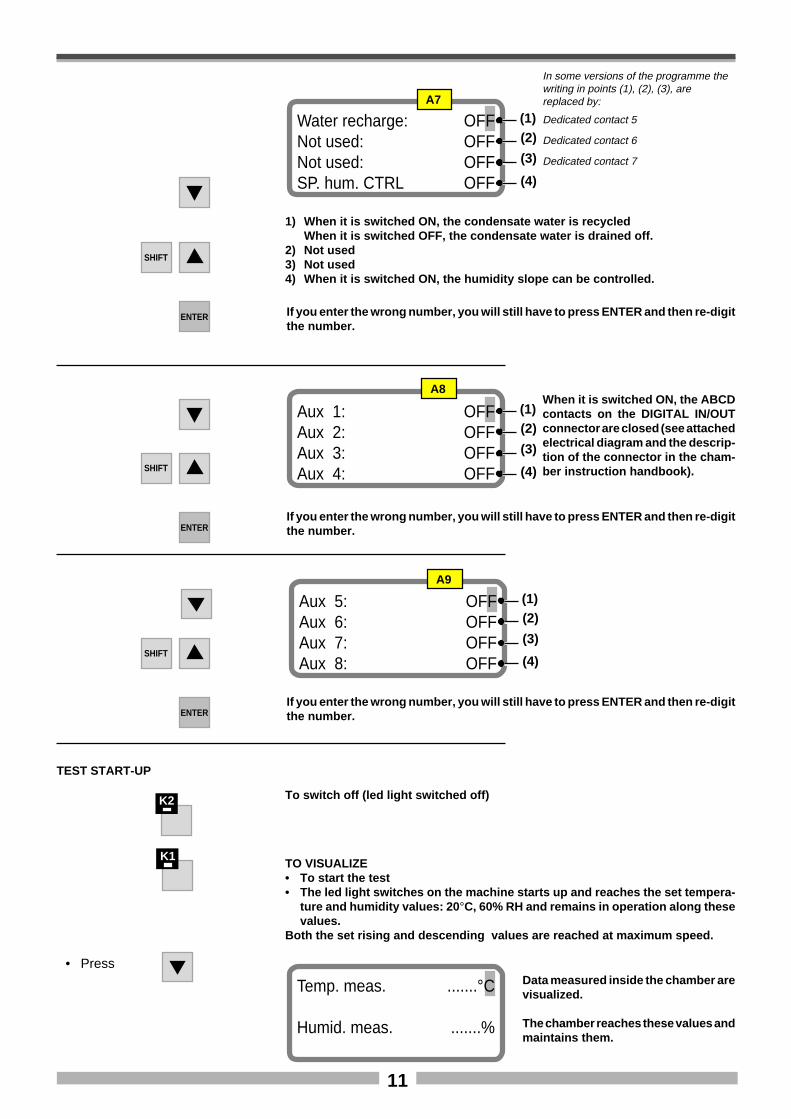
Water recharge: OFFNot used: OFFNot used: OFFSP. hum. CTRL OFF
A7
(1)(2)
(3)
(4)
1) When it is switched ON, the condensate water is recycledWhen it is switched OFF, the condensate water is drained off.
2) Not used3) Not used4) When it is switched ON, the humidity slope can be controlled.
SHIFT
ENTER If you enter the wrong number, you will still have to press ENTER and then re-digitthe number.
Aux 1: OFFAux 2: OFFAux 3: OFFAux 4: OFF
A8
(1)(2)
(3)
(4)
When it is switched ON, the ABCDcontacts on the DIGITAL IN/OUTconnector are closed (see attachedelectrical diagram and the descrip-tion of the connector in the cham-ber instruction handbook).
Aux 5: OFFAux 6: OFFAux 7: OFFAux 8: OFF
A9
(1)(2)
(3)
(4)
SHIFT
ENTERIf you enter the wrong number, you will still have to press ENTER and then re-digitthe number.
SHIFT
ENTERIf you enter the wrong number, you will still have to press ENTER and then re-digitthe number.
TEST START-UP
K1TO VISUALIZE• To start the test• The led light switches on the machine starts up and reaches the set tempera-
ture and humidity values: 20 °C, 60% RH and remains in operation along thesevalues.
Both the set rising and descending values are reached at maximum speed.
K2 To switch off (led light switched off)
• PressData measured inside the chamber arevisualized.
The chamber reaches these values andmaintains them.
Temp. meas. .......°C
Humid. meas. .......%
In some versions of the programme thewriting in points (1), (2), (3), arereplaced by:
Dedicated contact 5
Dedicated contact 6
Dedicated contact 7
12
10
15
20
25
30
35
5
5’ 10’ 15’
t= min.
Temp°C
Temperature Chart
40
50
60
70
80
90
30
20’ 25’ 30’
t= min.
% RH
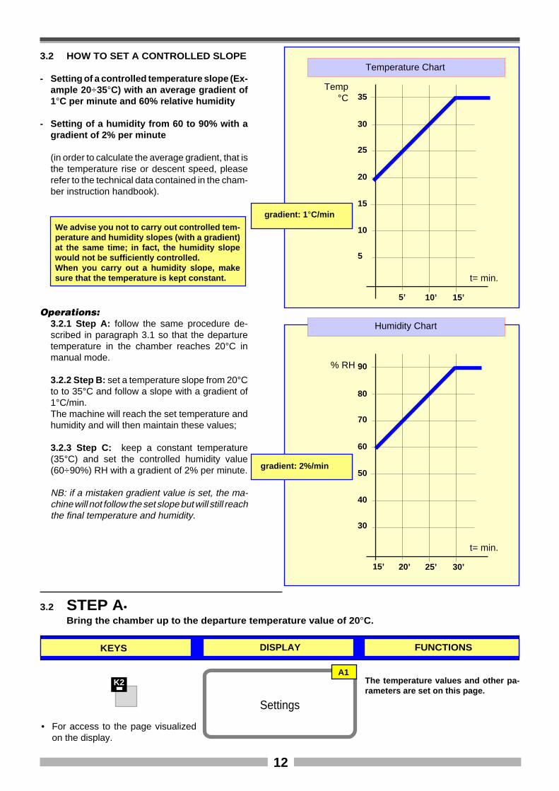
K2
Settings
A1The temperature values and other pa-rameters are set on this page.
3.2 STEP A•Bring the chamber up to the departure temperature value of 20 °C.
gradient: 1 °C/min
gradient: 2%/min
3.2 HOW TO SET A CONTROLLED SLOPE
- Setting of a controlled temperature slope (Ex-ample 20 ÷35°C) with an average gradient of1°C per minute and 60% relative humidity
- Setting of a humidity from 60 to 90% with agradient of 2% per minute
(in order to calculate the average gradient, that isthe temperature rise or descent speed, pleaserefer to the technical data contained in the cham-ber instruction handbook).
Humidity Chart
KEYS DISPLAY FUNCTIONS
Operations:3.2.1 Step A: follow the same procedure de-scribed in paragraph 3.1 so that the departuretemperature in the chamber reaches 20°C inmanual mode.
3.2.2 Step B: set a temperature slope from 20°Cto to 35°C and follow a slope with a gradient of1°C/min.The machine will reach the set temperature andhumidity and will then maintain these values;
3.2.3 Step C: keep a constant temperature(35°C) and set the controlled humidity value(60÷90%) RH with a gradient of 2% per minute.
NB: if a mistaken gradient value is set, the ma-chine will not follow the set slope but will still reachthe final temperature and humidity.
We advise you not to carry out controlled tem-perature and humidity slopes (with a gradient)at the same time; in fact, the humidity slopewould not be sufficiently controlled.When you carry out a humidity slope, makesure that the temperature is kept constant.
15’
• For access to the page visualizedon the display.
13
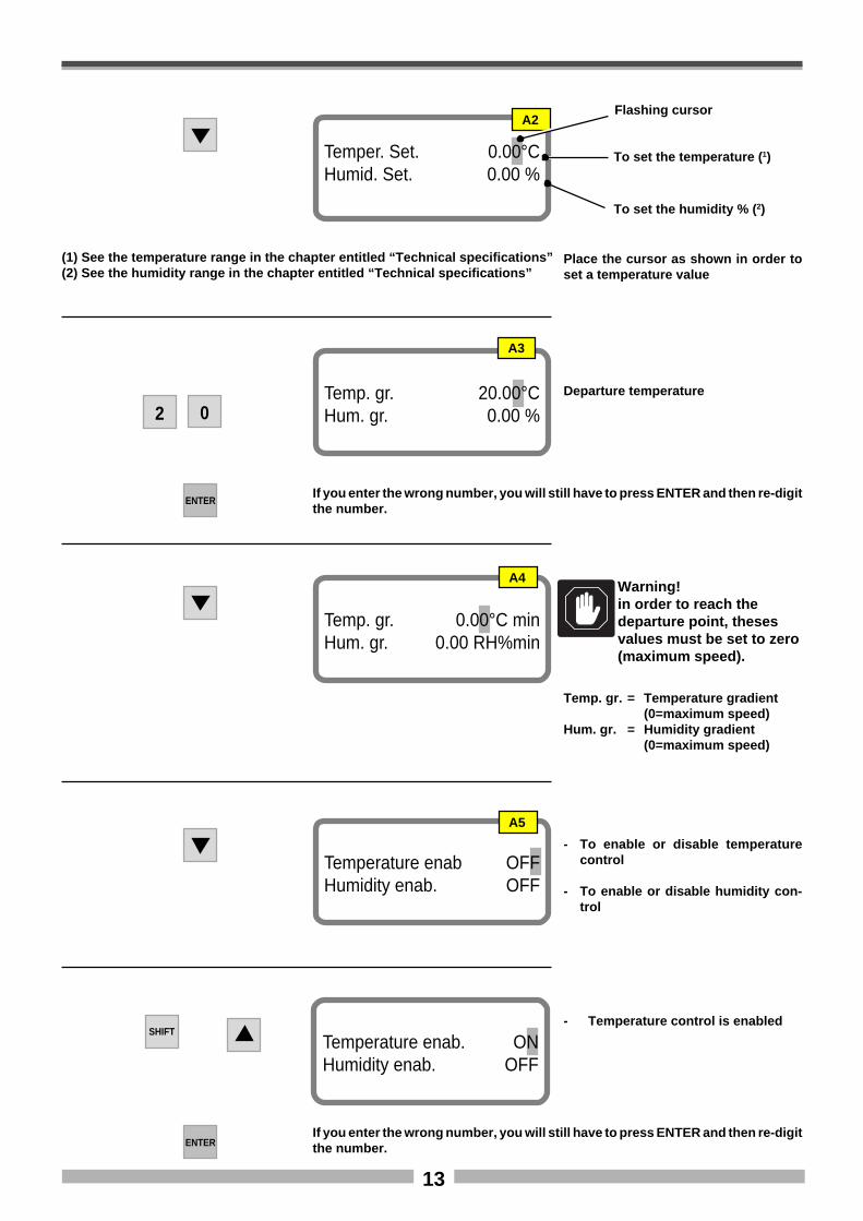
Temper. Set. 0.00°CHumid. Set. 0.00 %
A2Flashing cursor
To set the temperature ( 1)
To set the humidity % ( 2)
(1) See the temperature range in the chapter entitled “Technical specifications”(2) See the humidity range in the chapter entitled “Technical specifications”
A3
Place the cursor as shown in order toset a temperature value
Temp. gr. 20.00°CHum. gr. 0.00 %2 0
ENTERIf you enter the wrong number, you will still have to press ENTER and then re-digitthe number.
Departure temperature
Temp. gr. 0.00°C minHum. gr. 0.00 RH%min
Warning!in order to reach thedeparture point, thesesvalues must be set to zero(maximum speed).
A4
Temp. gr. = Temperature gradient(0=maximum speed)
Hum. gr. = Humidity gradient(0=maximum speed)
Temperature enab OFFHumidity enab. OFF
- To enable or disable temperaturecontrol
- To enable or disable humidity con-trol
A5
SHIFTTemperature enab. ONHumidity enab. OFF
- Temperature control is enabled
ENTERIf you enter the wrong number, you will still have to press ENTER and then re-digitthe number.
14
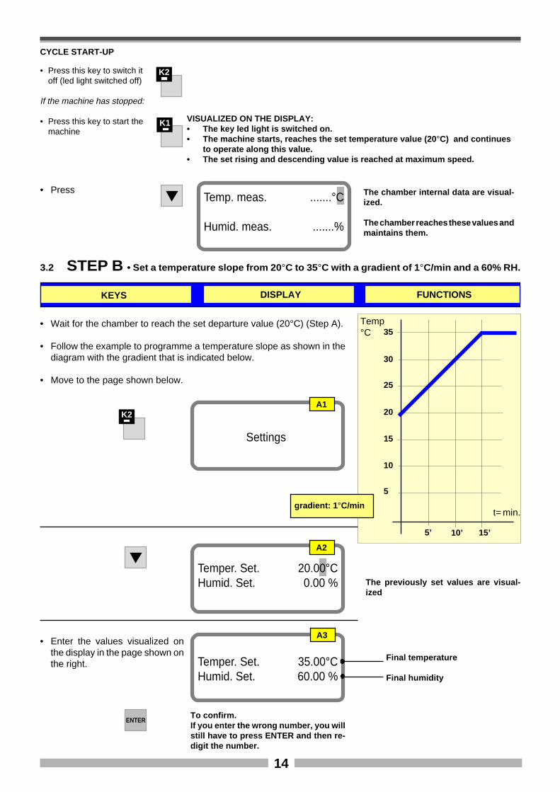
CYCLE START-UP
K1 VISUALIZED ON THE DISPLAY:• The key led light is switched on.• The machine starts, reaches the set temperature value (20 °C) and continues
to operate along this value.• The set rising and descending value is reached at maximum speed.
3.2 STEP B • Set a temperature slope from 20 °C to 35°C with a gradient of 1 °C/min and a 60% RH.
• Wait for the chamber to reach the set departure value (20°C) (Step A).
• Follow the example to programme a temperature slope as shown in thediagram with the gradient that is indicated below.
• Move to the page shown below.
10
15
20
25
30
35
5
5’ 10’ 15’
t= min.
Temp°C
gradient: 1 °C/min
K2
Settings
A1
A3
Temper. Set. 35.00°CHumid. Set. 60.00 %
ENTERTo confirm.If you enter the wrong number, you willstill have to press ENTER and then re-digit the number.
Temper. Set. 20.00°CHumid. Set. 0.00 %
A2
The previously set values are visual-ized
Final temperature
Final humidity
K2• Press this key to switch itoff (led light switched off)
If the machine has stopped:
• Press this key to start themachine
KEYS DISPLAY FUNCTIONS
• Press The chamber internal data are visual-ized.
The chamber reaches these values andmaintains them.
Temp. meas. .......°C
Humid. meas. .......%
• Enter the values visualized onthe display in the page shown onthe right.
15
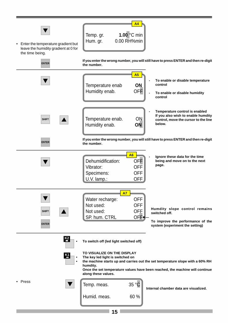
Temp. gr. 1.00 °C minHum. gr. 0.00 RH%min
• Enter the temperature gradient butleave the humidity gradient at 0 forthe time being.
A4
ENTERIf you enter the wrong number, you will still have to press ENTER and then re-digitthe number.
Temperature enab ONHumidity enab. OFF
- To enable or disable temperaturecontrol
- To enable or disable humiditycontrol
A5
SHIFT
- Temperature control is enabledIf you also wish to enable humditycontrol, move the cursor to the linebelow.
Temperature enab. ONHumidity enab. ON
ENTERIf you enter the wrong number, you will still have to press ENTER and then re-digitthe number.
Dehumidification: OFFVibrator: OFFSpecimens: OFFU.V. lamp.: OFF
A6 - Ignore these data for the timebeing and move on to the nextpage.
Water recharge: OFFNot used: OFFNot used: OFFSP. hum. CTRL OFF
A7
SHIFTHumdity slope control remainsswitched off.
To improve the performance of thesystem (experiment the setting)ENTER
K1 TO VISUALIZE ON THE DISPLAY• The key led light is switched on• the machine starts up and carries out the set temperature slope with a 60% RH
humdity.Once the set temperature values have been reached, the machine will continuealong these values.
K2• To switch off (led light switched off)
• Press
Internal chamber data are visualized.Temp. meas. 35 °C
Humid. meas. 60 %
16
10
15
20
25
30
35
5
5’ 10’ 15’
t= min.
Temp°C
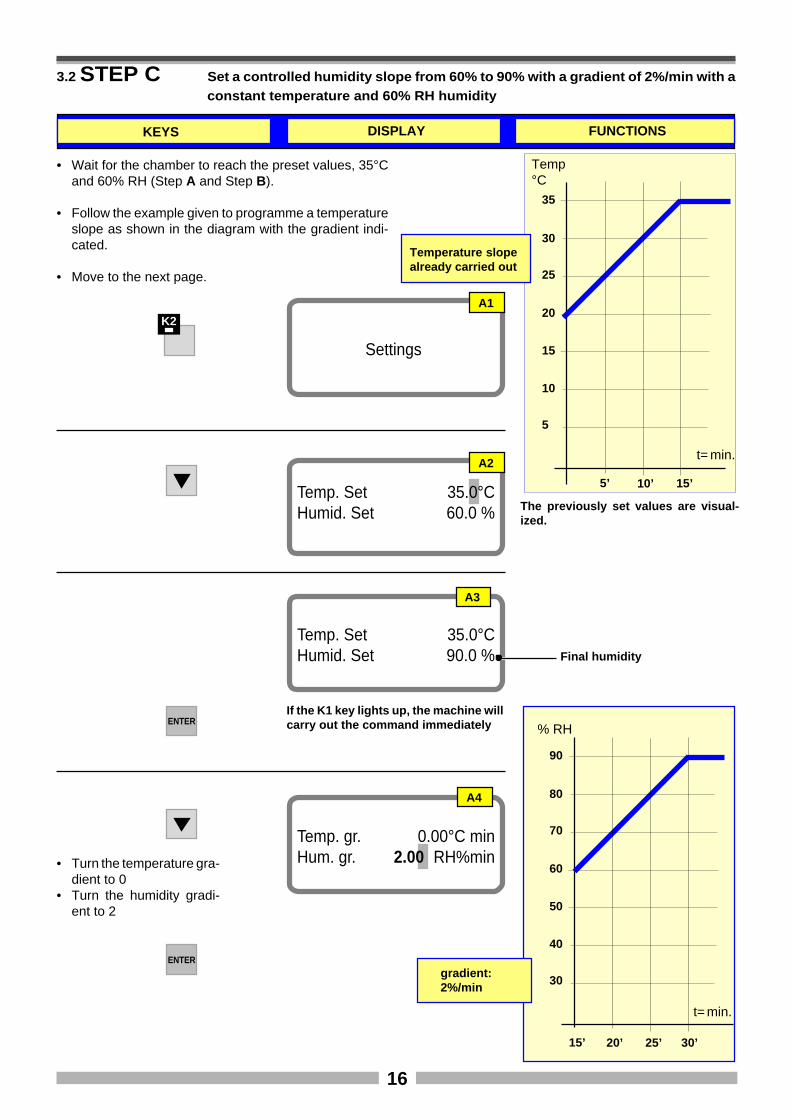
3.2 STEP C Set a controlled humidity slope from 60% to 90% with a gradient of 2%/min with aconstant temperature and 60% RH humidity
• Wait for the chamber to reach the preset values, 35°Cand 60% RH (Step A and Step B).
• Follow the example given to programme a temperatureslope as shown in the diagram with the gradient indi-cated.
• Move to the next page.
Temperature slopealready carried out
K2
Settings
A1
Temp. Set 35.0°CHumid. Set 60.0 %
A2
The previously set values are visual-ized.
Temp. gr. 0.00°C minHum. gr. 2.00 RH%min• Turn the temperature gra-
dient to 0• Turn the humidity gradi-
ent to 2
A4
ENTER
A3
Temp. Set 35.0°CHumid. Set 90.0 %
ENTERIf the K1 key lights up, the machine willcarry out the command immediately
Final humidity
40
50
60
70
80
90
30
15’ 20’ 25’
t= min.
% RH
KEYS DISPLAY FUNCTIONS
gradient:2%/min
30’
17
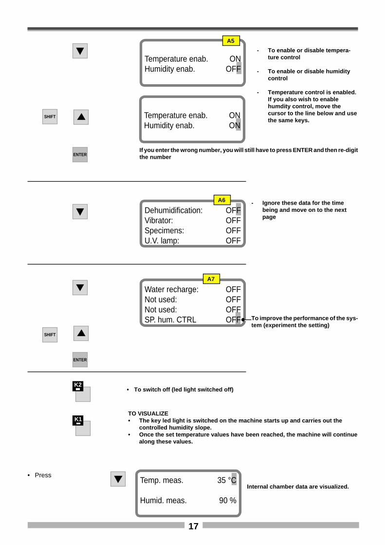
Temperature enab. ONHumidity enab. OFF
A5
SHIFT Temperature enab. ONHumidity enab. ON
ENTERIf you enter the wrong number, you will still have to press ENTER and then re-digitthe number
Dehumidification: OFFVibrator: OFFSpecimens: OFFU.V. lamp: OFF
A6 - Ignore these data for the timebeing and move on to the nextpage
Water recharge: OFFNot used: OFFNot used: OFFSP. hum. CTRL OFF
A7
SHIFT
To improve the performance of the sys-tem (experiment the setting)
ENTER
K1TO VISUALIZE• The key led light is switched on the machine starts up and carries out the
controlled humidity slope.• Once the set temperature values have been reached, the machine will continue
along these values.
K2• To switch off (led light switched off)
• Press
Internal chamber data are visualized.Temp. meas. 35 °C
Humid. meas. 90 %
- To enable or disable tempera-ture control
- To enable or disable humiditycontrol
- Temperature control is enabled.If you also wish to enablehumdity control, move thecursor to the line below and usethe same keys.
18
20
40
60
80
100
110
°C
h2 2 1,5 2,5 2 2
30
55
20
40
60
100
UR%
h1 1,5 2,5
9590
2
90
30 30
55
110
1 2,5
1 1,5 2,521
95 95
2 2 1,5 2 2
1,5
80
1,5
95
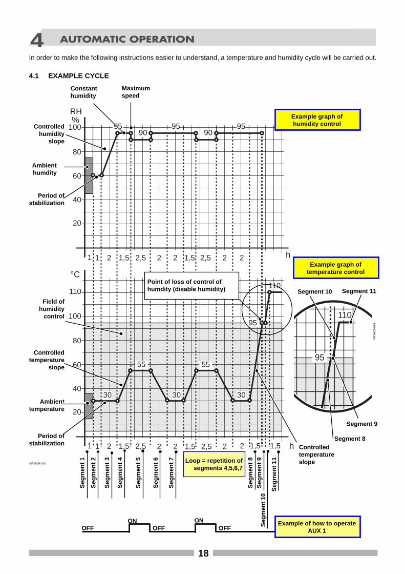
4 AUTOMATIC OPERATION
In order to make the following instructions easier to understand, a temperature and humidity cycle will be carried out.
OP2605-010
Example graph oftemperature control
Ambienttemperature
Ambienthumdity
Controlledhumidity
slope
Period ofstabilization
Period ofstabilization
Controlledtemperature
slope
Field ofhumidity
control
Example graph ofhumidity control
Seg
men
t 2
Seg
men
t 3
Seg
men
t 5
Seg
men
t 6 Loop = repetition ofsegments 4,5,6,7
Controlledtemperatureslope
Seg
men
t 8
Maximumspeed
ONOFF OFF OFF
ON Example of how to operateAUX 1
Constanthumidity
OP
26
05
-01
5
95
110
Seg
men
t 1
Seg
men
t 7
Seg
men
t 4
Point of loss of control ofhumdity (disable humidity)
Segment 8
Segment 9
Segment 11Segment 10
Seg
men
t 9S
egm
ent 1
0
Seg
men
t 11
4.1 EXAMPLE CYCLE
RH
19
1 2 3 4 5 6 7 8 9 10 11.........
OFF
ON
ON
ON
30
0.00
1.00
ON
ON
ON
60
0.00
3.00
OFF
OFF
OFF
OFF
OFF
OFF
OFF
OFF
OFF
OFF
OFF
OFF
OFF
OFF
SAVE
1
1:0:0
ON
ON
OFF
OFF
30
0.00
1.00
ON
OFF
OFF
60
0.00
3.00
OFF
OFF
OFF
OFF
OFF
OFF
OFF
OFF
OFF
OFF
OFF
OFF
OFF
OFF
SAVE
2
2:0:0
ON
ON
OFF
OFF
30
0.00
1.00
ON
OFF
OFF
95
0.29
3.00
OFF
OFF
OFF
OFF
OFF
OFF
OFF
OFF
OFF
OFF
OFF
OFF
OFF
OFF
SAVE
3
1:30:0
ON
ON
ON
OFF
55
0.28
1.00
ON
ON
OFF
95
0.00
3.00
OFF
OFF
OFF
OFF
OFF
OFF
OFF
OFF
OFF
OFF
OFF
OFF
OFF
OFF
SAVE
4
2:30:0
ON
ON
OFF
OFF
55
0.00
1.00
ON
OFF
ON
90
20
3.00
OFF
OFF
OFF
OFF
OFF
ON
ON
OFF
OFF
OFF
OFF
OFF
OFF
OFF
SAVE
5
2:0:0
ON
ON
OFF
OFF
30
0.21
1.00
ON
OFF
ON
95
20
3.00
OFF
OFF
OFF
OFF
OFF
ON
OFF
OFF
OFF
OFF
OFF
OFF
OFF
OFF
SAVE
6
2:0:0
ON
ON
OFF
OFF
30
0.00
1.00
ON
OFF
OFF
95
0.00
3.00
OFF
OFF
OFF
OFF
OFF
ON
OFF
OFF
OFF
OFF
OFF
OFF
OFF
OFF
SAVE
7
1:30:0
ON
ON
OFF
OFF
95
0.70
1.00
ON
ON
OFF
95
0.00
3.00
OFF
OFF
OFF
OFF
OFF
ON
OFF
OFF
OFF
OFF
OFF
OFF
OFF
OFF
SAVE
8
0:0:5
ON
ON
OFF
OFF
95
0.00
1.00
OFF
OFF
ON
95
0.00
3.00
OFF
OFF
OFF
OFF
OFF
ON
OFF
OFF
OFF
OFF
OFF
OFF
OFF
OFF
SAVE
9
0:0:0
OFF
ON
ON
ON
110
0.00
1.00
OFF
OFF
OFF
0.00
0.00
3.00
OFF
OFF
OFF
OFF
OFF
ON
OFF
OFF
OFF
OFF
OFF
OFF
OFF
OFF
SAVE
10
1:30:0
ON
ON
ON
OFF
110
0.00
1.00
OFF
OFF
OFF
0.00
0.00
3.00
OFF
OFF
OFF
OFF
OFF
ON
OFF
OFF
OFF
OFF
OFF
OFF
OFF
OFF
SAVE
11
OK
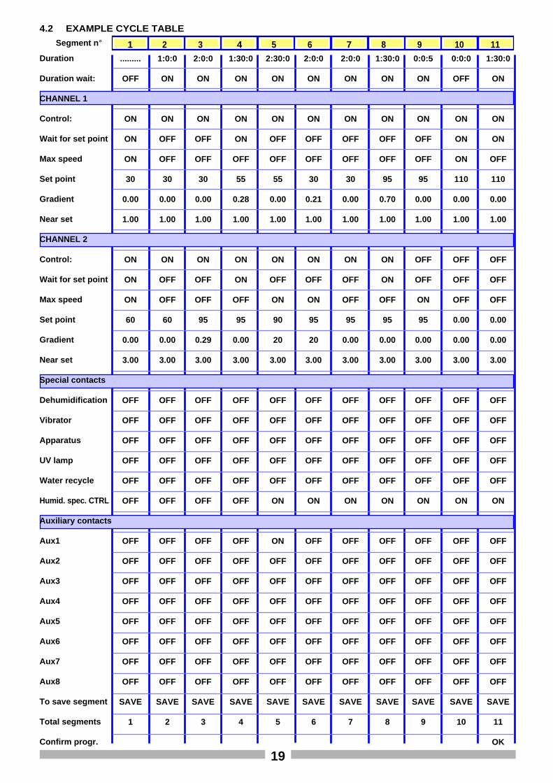
4.2 EXAMPLE CYCLE TABLE
Segment n °
Duration
Duration wait:
CHANNEL 1
Control:
Wait for set point
Max speed
Set point
Gradient
Near set
CHANNEL 2
Control:
Wait for set point
Max speed
Set point
Gradient
Near set
Special contacts
Dehumidification
Vibrator
Apparatus
UV lamp
Water recycle
Humid. spec. CTRL
Auxiliary contacts
Aux1
Aux2
Aux3
Aux4
Aux5
Aux6
Aux7
Aux8
To save segment
Total segments
Confirm progr.
20
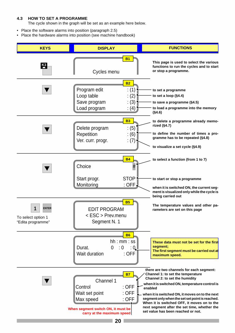
• Place the software alarms into position (paragraph 2.5)• Place the hardware alarms into position (see machine handbook)
K3
Cycles menu
B1This page is used to select the variousfunctions to run the cycles and to startor stop a programme.
B2
Program edit : (1)Loop table : (2)Save program : (3)Load program : (4)
B3
Delete program : (5)Repetition : (6)Ver. curr. progr. : (7)
to set a programme
to set a loop (§4.4)
to save a programme (§4.5)
to load a programme into the memory(§4.6)
to delete a programme already memo-rized (§4.7)
to define the number of times a pro-gramme has to be repeated (§4.8)
to visualize a set cycle (§4.9)
B4
Choice #
Start progr. STOPMonitoring : OFF
to select a function (from 1 to 7)
to start or stop a programme
when it is switched ON, the current seg-ment is visualized only while the cycle isbeing carried out
1
KEYS DISPLAY FUNCTIONS
To select option 1“Edita programme”
EDIT PROGRAM< ESC > Prev.menu
Segment N. 1
B5
B6
hh : mm : ssDurat. 0 : 0 : 0Wait duration : OFF
These data must not be set for the firstsegment;The first segment must be carried out atmaximum speed.
4.3 HOW TO SET A PROGRAMMEThe cycle shown in the graph will be set as an example here below.
B7
Channel 1Control : OFFWait set point : OFFMax speed : OFF
there are two channels for each segment:Channel 1: to set the temperatureChannel 2: to set the humidity
when it is switched ON, temperature control isenabled
when it is switched ON, it moves on to the nextsegment only when the set set point is reached.When it is switched OFF, it moves on to thenext segment after the set time, whether theset value has been reached or not.
When segment switch ON, it must becarry at the maximum speed
The temperature values and other pa-rameters are set on this pageENTER
21
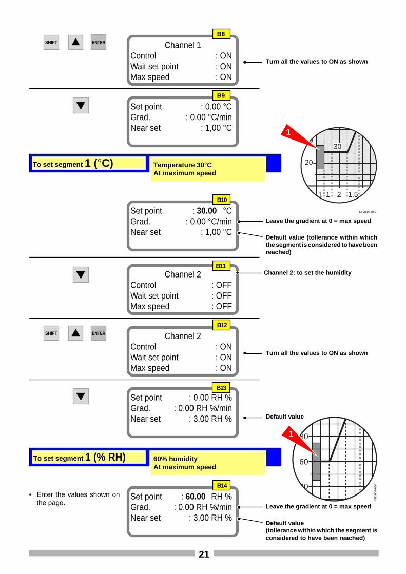
Turn all the values to ON as shown
SHIFT
B8
Channel 1Control : ONWait set point : ONMax speed : ON
ENTER
B9
Set point : 0.00 °CGrad. : 0.00 °C/minNear set : 1,00 °C
B10
Set point : 30.00 °CGrad. : 0.00 °C/minNear set : 1,00 °C
To set segment 1 (°C) Temperature 30 °CAt maximum speed
Leave the gradient at 0 = max speed
Default value (tollerance within whichthe segment is considered to have beenreached)
Channel 2Control : OFFWait set point : OFFMax speed : OFF
Channel 2: to set the humidity
Turn all the values to ON as shown
SHIFT
B12
Channel 2Control : ONWait set point : ONMax speed : ON
ENTER
20
4030
1 1,5 2,521
OP2605-050
Set point : 0.00 RH %Grad. : 0.00 RH %/minNear set : 3,00 RH %
1
B13
B14
Set point : 60.00 RH %Grad. : 0.00 RH %/minNear set : 3,00 RH %
To set segment 1 (% RH) 60% humidityAt maximum speed
Leave the gradient at 0 = max speed
Default value(tollerance within which the segment isconsidered to have been reached)
40
60
80
90
OP
26
05
-06
0
1
• Enter the values shown onthe page.
B11
Default value
22
B15
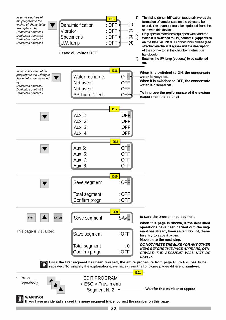
Dehumidification : OFFVibrator : OFFSpecimens : OFFU.V. lamp : OFF
(1)
(2)
(3)
(4)
1) The rising dehumidification (optional) avoids theformation of condensate on the object to betested. The chamber must be equipped from thestart with this device.
2) Only special machines equipped with vibrator3) When it is switched to ON, contact E (Apparatus)
on the DIGITAL IN/OUT connector is closed (seeattached electrical diagram and the descriptionof the connector in the chamber instructionhandbook).
4) Enables the UV lamp (optional) to be switchedon.
Leave all values OFF
Water recharge: OFFNot used: OFFNot used: OFFSP. hum. CTRL OFF
B16 When it is switched to ON, the condensatewater is recycled.When it is switched to OFF, the condensatewater is drained off.
Aux 1: OFFAux 2: OFFAux 3: OFFAux 4: OFF
B17
Aux 5: OFFAux 6: OFFAux 7: OFFAux 8: OFF
B18
Save segment : OFF
Total segment : OFFConfirm progr : OFF
B19
to save the programmed segmentSHIFT ENTER Save segment : SAVEB20
Once the first segment has been finished, the entire procedure from page B5 to B20 has to berepeated. To simplify the explanations, we have given the following pages different numbers.
B21
EDIT PROGRAM< ESC > Prev. menu
Segment N. 2 Wait for this number to appear
• Pressrepeatedly
This page is visualizedSave segment : OFF
Total segment : 0Confirm progr : OFF
When this page is shown, if the describedoperations have been carried out, the seg-ment has already been saved. Do not, there-fore, try to save it again.Move on to the next step.DO NOT PRESS THE KEY OR ANY OTHERKEYS BEFORE THIS PAGE APPEARS, OTH-ERWISE THE SEGMENT WILL NOT BESAVED.
WARNING!If you have accidentally saved the same segment twice, correct the number on this page.
To improve the performance of the system(experiment the setting)
In some versions ofthe programme thewriting of these fieldsare replaced by:Dedicated contact 1Dedicated contact 2Dedicated contact 3Dedicated contact 4
In some versions of theprogramme the writing ofthese fields are replacedby:Dedicated contact 5Dedicated contact 6Dedicated contact 7
23
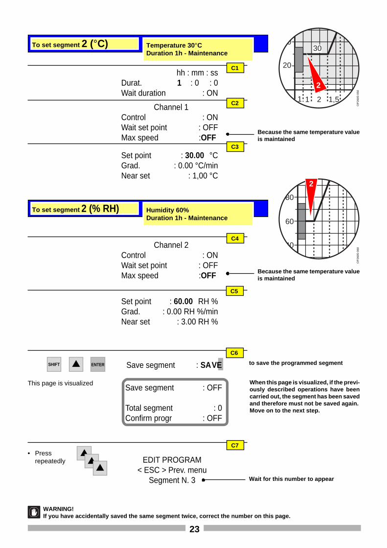
To set segment 2 (% RH) Humidity 60%Duration 1h - Maintenance
To set segment 2 (°C) Temperature 30 °CDuration 1h - Maintenance
hh : mm : ssDurat. 1 : 0 : 0Wait duration : ON
C1
Channel 1Control : ONWait set point : OFFMax speed :OFF
Set point : 30.00 °CGrad. : 0.00 °C/minNear set : 1,00 °C
C2
C3
Channel 2Control : ONWait set point : OFFMax speed :OFF
C4
C5
Because the same temperature valueis maintained
20
4030
1 1,5 2,521
OP
26
05
-05
0
40
60
80
90
OP
26
05
-06
0
Because the same temperature valueis maintained
Set point : 60.00 RH %Grad. : 0.00 RH %/minNear set : 3.00 RH %
2
2
C6
to save the programmed segmentSHIFT ENTER Save segment : SAVE
C7
EDIT PROGRAM< ESC > Prev. menu
Segment N. 3 Wait for this number to appear
• Pressrepeatedly
This page is visualizedSave segment : OFF
Total segment : 0Confirm progr : OFF
When this page is visualized, if the previ-ously described operations have beencarried out, the segment has been savedand therefore must not be saved again.Move on to the next step.
WARNING!If you have accidentally saved the same segment twice, correct the number on this page.
24
60
80
100
UR%
9590
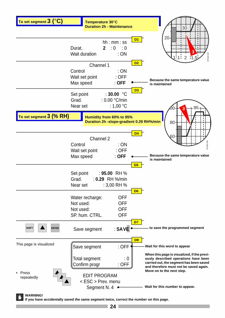
To set segment 3 (% RH) Humidity from 60% to 95%Duration 2h -slope-gradient 0.29 RH%/min
To set segment 3 (°C) Temperature 30 °CDuration 2h - Maintenance
hh : mm : ssDurat. 2 : 0 : 0Wait duration : ON
D1
Channel 1Control : ONWait set point : OFFMax speed : OFF
Set point : 30.00 °CGrad. : 0.00 °C/minNear set : 1,00 °C
D2
D3
Channel 2Control : ONWait set point : OFFMax speed : OFF
D4
D5
Because the same temperature valueis maintained
20
4030
1 1,5 2,521
OP
26
05
-05
0O
P2
60
5-0
65
Because the same temperature valueis maintained
Set point : 95.00 RH %Grad. : 0.29 RH %/minNear set : 3,00 RH %
D7
to save the programmed segmentSave segment : SAVE
D8
EDIT PROGRAM< ESC > Prev. menu
Segment N. 4 Wait for this number to appear.
3
3
Water recharge: OFFNot used: OFFNot used: OFFSP. hum. CTRL. OFF
D6
• Pressrepeatedly
SHIFT ENTER
This page is visualizedSave segment : OFF
Total segment : 0Confirm progr : OFF
When this page is visualized, if the previ-ously described operations have beencarried out, the segment has been savedand therefore must not be saved again.Move on to the next step.
WARNING!If you have accidentally saved the same segment twice, correct the number on this page.
Wait for this word to appear
25
9590
30
55
hh : mm : ssDurat. 1 : 30 : 0Wait duration : ON
E1
Channel 1Control : ONWait set point : ONMax speed : OFF
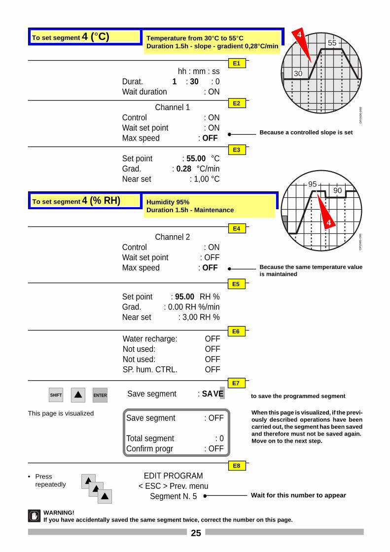
Set point : 55.00 °CGrad. : 0.28 °C/minNear set : 1,00 °C
E2
E3
Channel 2Control : ONWait set point : OFFMax speed : OFF
E4
E5
Because a controlled slope is set
OP
26
05
-08
0O
P2
60
5-0
90
Because the same temperature valueis maintained
Set point : 95.00 RH %Grad. : 0.00 RH %/minNear set : 3,00 RH %
E7
to save the programmed segmentSave segment : SAVE
E8
EDIT PROGRAM< ESC > Prev. menu
Segment N. 5 Wait for this number to appear
4
Water recharge: OFFNot used: OFFNot used: OFFSP. hum. CTRL. OFF
E6
To set segment 4 (% RH) Humidity 95%Duration 1.5h - Maintenance
To set segment 4 (°C) Temperature from 30 °C to 55°CDuration 1.5h - slope - gradient 0,28 °C/min
4
SHIFT ENTER
This page is visualizedSave segment : OFF
Total segment : 0Confirm progr : OFF
When this page is visualized, if the previ-ously described operations have beencarried out, the segment has been savedand therefore must not be saved again.Move on to the next step.
WARNING!If you have accidentally saved the same segment twice, correct the number on this page.
• Pressrepeatedly
26
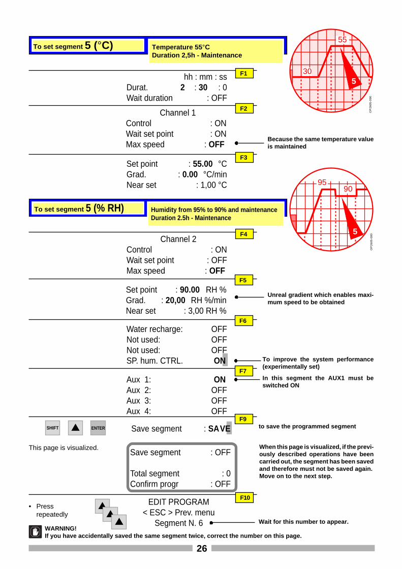
To set segment 5 (°C) Temperature 55 °CDuration 2,5h - Maintenance
hh : mm : ssDurat. 2 : 30 : 0Wait duration : OFF
F1
Channel 1Control : ONWait set point : ONMax speed : OFF
Set point : 55.00 °CGrad. : 0.00 °C/minNear set : 1,00 °C
F2
F3
Because the same temperature valueis maintained
OP
26
05
-09
0
9590
Channel 2Control : ONWait set point : OFFMax speed : OFF
F4
F5
OP
26
05
-08
0
Set point : 90.00 RH %Grad. : 20,00 RH %/minNear set : 3,00 RH %
F9to save the programmed segmentSave segment : SAVE
F10EDIT PROGRAM< ESC > Prev. menu
Segment N. 6 Wait for this number to appear.
5
Water recharge: OFFNot used: OFFNot used: OFFSP. hum. CTRL. ON To improve the system performance
(experimentally set)
F6
To set segment 5 (% RH) Humidity from 95% to 90% and maintenanceDuration 2.5h - Maintenance
30
55
5
Unreal gradient which enables maxi-mum speed to be obtained
F7
Aux 1: ONAux 2: OFFAux 3: OFFAux 4: OFF
In this segment the AUX1 must beswitched ON
SHIFT ENTER
• Pressrepeatedly
WARNING!If you have accidentally saved the same segment twice, correct the number on this page.
This page is visualized.Save segment : OFF
Total segment : 0Confirm progr : OFF
When this page is visualized, if the previ-ously described operations have beencarried out, the segment has been savedand therefore must not be saved again.Move on to the next step.
27
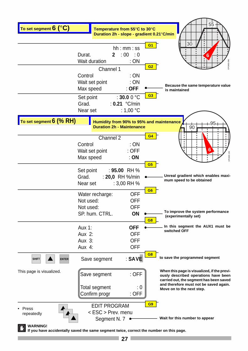
To set segment 6 (°C) Temperature from 55 °C to 30°CDuration 2h - slope - gradient 0.21 °C/min
hh : mm : ssDurat. 2 : 00 : 0Wait duration : ON
G1
Channel 1Control : ONWait set point : ONMax speed : OFF
Set point : 30.0 0 °CGrad. : 0.21 °C/minNear set : 1,00 °C
G2
G3
Because the same temperature valueis maintained
OP
26
05
-09
0
Channel 2Control : ONWait set point : OFFMax speed : ON
G4
G5
OP
26
05
-10
0
Set point : 95.00 RH %Grad. : 20,0 RH %/minNear set : 3,00 RH %
G8to save the programmed segmentSave segment : SAVE
G9EDIT PROGRAM< ESC > Prev. menu
Segment N. 7 Wait for this number to appear
Water recharge: OFFNot used: OFFNot used: OFFSP. hum. CTRL. ON To improve the system performance
(experimentally set)
G6
To set segment 6 (% RH) Humidity from 90% to 95% and maintenanceDuration 2h - Maintenance
30
55
6
Unreal gradient which enables maxi-mum speed to be obtained
Aux 1: OFFAux 2: OFFAux 3: OFFAux 4: OFF
In this segment the AUX1 must beswitched OFF
G8
SHIFT ENTER
• Pressrepeatedly
WARNING!If you have accidentally saved the same segment twice, correct the number on this page.
This page is visualized.Save segment : OFF
Total segment : 0Confirm progr : OFF
When this page is visualized, if the previ-ously described operations have beencarried out, the segment has been savedand therefore must not be saved again.Move on to the next step.
9095
6
28
9095
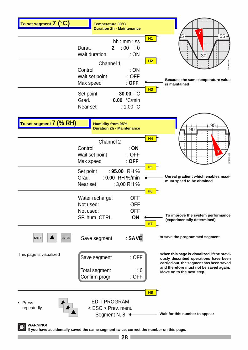
To set segment 7 (°C) Temperature 30 °CDuration 2h - Maintenance
hh : mm : ssDurat. 2 : 00 : 0Wait duration : ON
H1
Channel 1Control : ONWait set point : OFFMax speed : OFF
Set point : 30.00 °CGrad. : 0.00 °C/minNear set : 1,00 °C
H2
H3
Because the same temperature valueis maintained
OP
26
05
-11
0
Channel 2Control : ONWait set point : OFFMax speed : OFF
H4
H5
OP
26
05
-10
0
Set point : 95.00 RH %Grad. : 0.00 RH %/minNear set : 3,00 RH %
to save the programmed segmentSave segment : SAVE
H8
EDIT PROGRAM< ESC > Prev. menu
Segment N. 8 Wait for this number to appear
7
Water recharge: OFFNot used: OFFNot used: OFFSP. hum. CTRL. ON To improve the system performance
(experimentally determined)
H6
To set segment 7 (% RH) Humidity from 95%Duration 2h - Maintenance
55
30
557
Unreal gradient which enables maxi-mum speed to be obtained
H7
SHIFT ENTER
This page is visualizedSave segment : OFF
Total segment : 0Confirm progr : OFF
When this page is visualized, if the previ-ously described operations have beencarried out, the segment has been savedand therefore must not be saved again.Move on to the next step.
WARNING!If you have accidentally saved the same segment twice, correct the number on this page.
• Pressrepeatedly
29
95
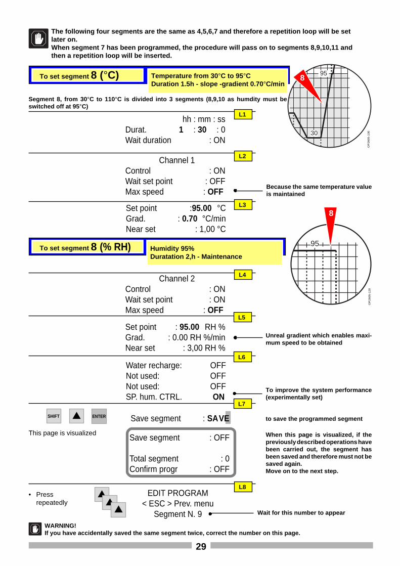
The following four segments are the same as 4,5,6,7 and therefore a repetition loop will be setlater on.When segment 7 has been programmed, the procedure will pass on to segments 8,9,10,11 andthen a repetition loop will be inserted.
To set segment 8 (°C) Temperature from 30 °C to 95°CDuration 1.5h - slope -gradient 0.70 °C/min
hh : mm : ssDurat. 1 : 30 : 0Wait duration : ON
L1
Channel 1Control : ONWait set point : OFFMax speed : OFF
Set point :95.00 °CGrad. : 0.70 °C/minNear set : 1,00 °C
L2
L3
Because the same temperature valueis maintained
OP
26
05
-13
0
Channel 2Control : ONWait set point : ONMax speed : OFF
L4
L5
OP
26
05
-12
0
Set point : 95.00 RH %Grad. : 0.00 RH %/minNear set : 3,00 RH %
to save the programmed segmentSave segment : SAVE
L8EDIT PROGRAM
< ESC > Prev. menuSegment N. 9
Water recharge: OFFNot used: OFFNot used: OFFSP. hum. CTRL. ON
To improve the system performance(experimentally set)
L6
To set segment 8 (% RH) Humidity 95%Duratation 2,h - Maintenance
95
30
8
Unreal gradient which enables maxi-mum speed to be obtained
L7
Segment 8, from 30 °C to 110°C is divided into 3 segments (8,9,10 as humdity must beswitched off at 95 °C)
8
Wait for this number to appear
SHIFT ENTER
This page is visualizedSave segment : OFF
Total segment : 0Confirm progr : OFF
When this page is visualized, if thepreviously described operations havebeen carried out, the segment hasbeen saved and therefore must not besaved again.Move on to the next step.
• Pressrepeatedly
WARNING!If you have accidentally saved the same segment twice, correct the number on this page.
30
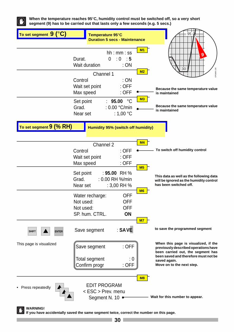
When the temperature reaches 95 °C, humidity control must be switched off, so a very shortsegment (9) has to be carried out that lasts only a few seconds (e.g. 5 secs.)
To set segment 9 (°C) Temperature 95 °CDuration 5 secs - Maintenance
hh : mm : ssDurat. 0 : 0 : 5Wait duration : ON
M1
Channel 1Control : ONWait set point : OFFMax speed : OFF
Set point : 95.00 °CGrad. : 0.00 °C/minNear set : 1,00 °C
M2
M3
Because the same temperature valueis maintained
OP
26
05
-13
0
Channel 2Control : OFFWait set point : OFFMax speed : OFF
M4
M5
Set point : 95.00 RH %Grad. : 0.00 RH %/minNear set : 3,00 RH %
to save the programmed segmentSave segment : SAVE
M8
EDIT PROGRAM< ESC > Prev. menu
Segment N. 10
Water recharge: OFFNot used: OFFNot used: OFFSP. hum. CTRL. ON
This data as well as the following datawill be ignored as the humidity controlhas been switched off.
M6
To set segment 9 (% RH) Humidity 95% (switch off humidity)
95
30
To switch off humidity control
M7
Wait for this number to appear.
9
Because the same temperature valueis maintained
• Press repeatedly
SHIFT ENTER
WARNING!If you have accidentally saved the same segment twice, correct the number on this page.
This page is visualizedSave segment : OFF
Total segment : 0Confirm progr : OFF
When this page is visualized, if thepreviously described operations havebeen carried out, the segment hasbeen saved and therefore must not besaved again.Move on to the next step.
31
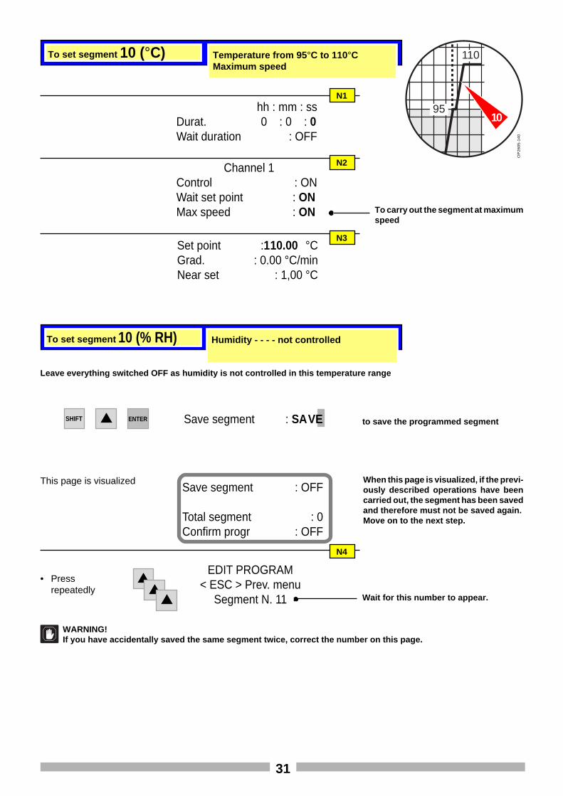
To set segment 10 (°C) Temperature from 95 °C to 110°CMaximum speed
hh : mm : ssDurat. 0 : 0 : 0Wait duration : OFF
N1
Channel 1Control : ONWait set point : ONMax speed : ON
Set point :110.00 °CGrad. : 0.00 °C/minNear set : 1,00 °C
N2
N3
To carry out the segment at maximumspeed
OP
26
05
-14
0
to save the programmed segmentSave segment : SAVE
N4
EDIT PROGRAM< ESC > Prev. menu
Segment N. 11
To set segment 10 (% RH) Humidity - - - - not controlled
95
110
Wait for this number to appear.
10
Leave everything switched OFF as humidity is not controlled in this temperature range
• Pressrepeatedly
SHIFT ENTER
This page is visualizedSave segment : OFF
Total segment : 0Confirm progr : OFF
When this page is visualized, if the previ-ously described operations have beencarried out, the segment has been savedand therefore must not be saved again.Move on to the next step.
WARNING!If you have accidentally saved the same segment twice, correct the number on this page.
32
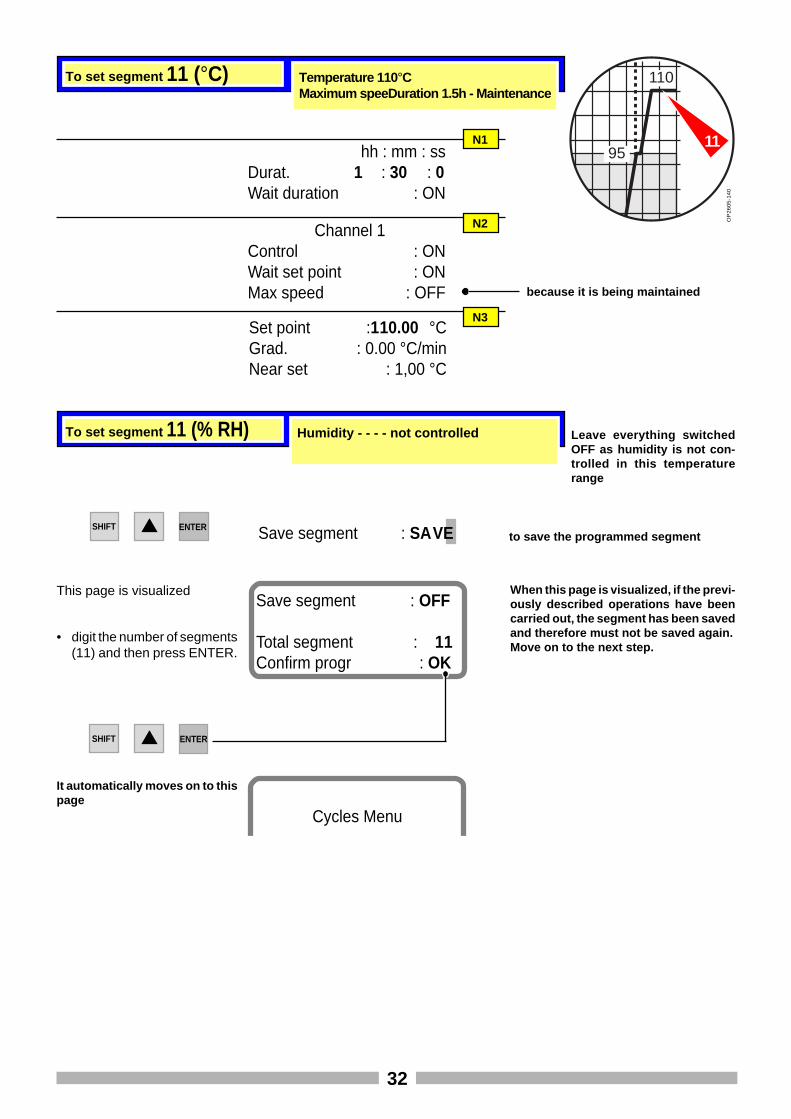
To set segment 11 (°C) Temperature 110 °CMaximum speeDuration 1.5h - Maintenance
hh : mm : ssDurat. 1 : 30 : 0Wait duration : ON
N1
Channel 1Control : ONWait set point : ONMax speed : OFF
Set point :110.00 °CGrad. : 0.00 °C/minNear set : 1,00 °C
N2
N3
because it is being maintained
OP
26
05
-14
0
to save the programmed segmentSave segment : SAVE
To set segment 11 (% RH) Humidity - - - - not controlled
95
110
11
Leave everything switchedOFF as humidity is not con-trolled in this temperaturerange
SHIFT ENTER
This page is visualizedSave segment : OFF
Total segment : 11Confirm progr : OK
When this page is visualized, if the previ-ously described operations have beencarried out, the segment has been savedand therefore must not be saved again.Move on to the next step.
SHIFT
• digit the number of segments(11) and then press ENTER.
Cycles Menu
It automatically moves on to thispage
ENTER
33
2 2 1,5 2,5 2 2
95
1,5 2,5
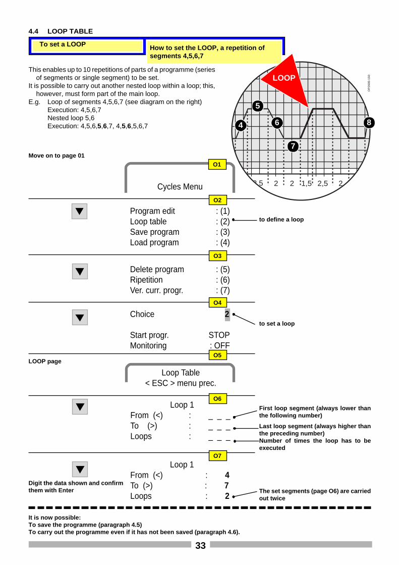
To set a LOOP How to set the LOOP, a repetition ofsegments 4,5,6,7
OP
26
05
-15
0LOOP
4
5
6
7
8
Cycles Menu
Program edit : (1)Loop table : (2)Save program : (3)Load program : (4)
Delete program : (5)Ripetition : (6)Ver. curr. progr. : (7)
to define a loop
Choice 2
Start progr. STOPMonitoring : OFF
to set a loop
Move on to page 01
LOOP page
O2
O3
O4
O1
Loop 1From (<) : _ _ _To (>) : _ _ _Loops : _ _ _
O6
First loop segment (always lower thanthe following number)
Last loop segment (always higher thanthe preceding number)Number of times the loop has to beexecuted
Loop 1From (<) : 4To (>) : 7Loops : 2
O7
Digit the data shown and confirmthem with Enter
4.4 LOOP TABLE
It is now possible:To save the programme (paragraph 4.5)To carry out the programme even if it has not been saved (paragraph 4.6).
This enables up to 10 repetitions of parts of a programme (seriesof segments or single segment) to be set.
It is possible to carry out another nested loop within a loop; this,however, must form part of the main loop.
E.g. Loop of segments 4,5,6,7 (see diagram on the right)Execution: 4,5,6,7Nested loop 5,6Execution: 4,5,6,5,6,7, 4,5,6,5,6,7
The set segments (page O6) are carriedout twice
O5
Loop Table< ESC > menu prec.
34
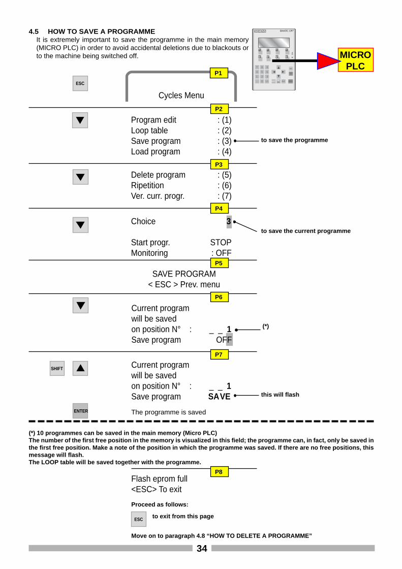
4.5 HOW TO SAVE A PROGRAMMEIt is extremely important to save the programme in the main memory(MICRO PLC) in order to avoid accidental deletions due to blackouts orto the machine being switched off.
Cycles Menu
Program edit : (1)Loop table : (2)Save program : (3)Load program : (4)
Delete program : (5)Ripetition : (6)Ver. curr. progr. : (7)
to save the programme
Choice 3
Start progr. STOPMonitoring : OFF
to save the current programme
SAVE PROGRAM< ESC > Prev. menu
P2
P3
P4
P1
P5
Current programwill be savedon position N° : _ _ 1Save program OFF
P6
(*) 10 programmes can be saved in the main memory (Micro PLC)The number of the first free position in the memory is visualized in this field; the programme can, in fact, only be saved inthe first free position. Make a note of the position in which the programme was saved. If there are no free positions, thismessage will flash.The LOOP table will be saved together with the programme.
ESC
Flash eprom full<ESC> To exit
Proceed as follows:
ESC to exit from this page
(*)
Move on to paragraph 4.8 “HOW TO DELETE A PROGRAMME”
SHIFT
P7
Current programwill be savedon position N° : _ _ 1Save program SAVE this will flash
The programme is saved
SIEMENS SIMATIC OP7
F1 F2 F3 F4
K1 K2 K3 K4
7 8 9
4 5 6
1 2 3. 0 +/- SHIFT
INSDEL
HELP ENTER
ACX
ESC
MICROPLC
P8
ENTER
35
Cycles Menu
Q6
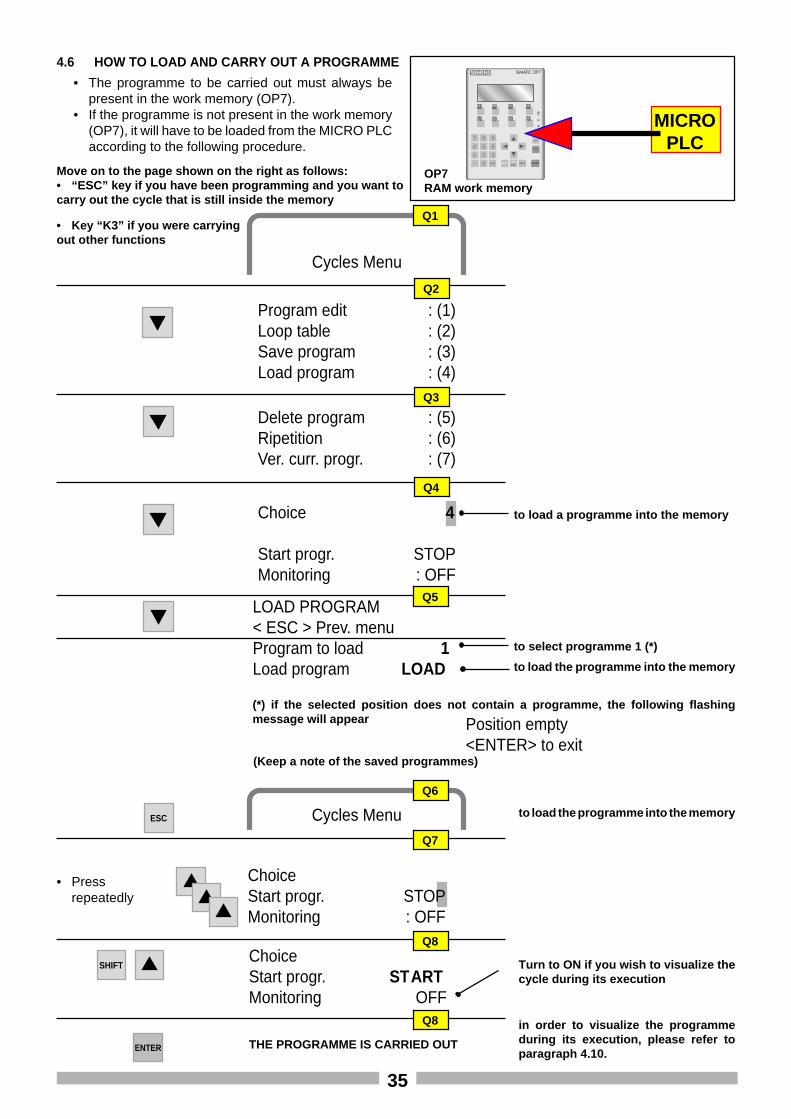
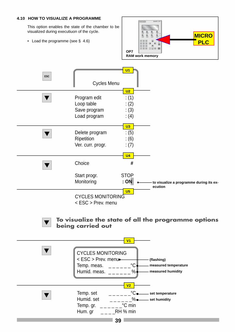
4.6 HOW TO LOAD AND CARRY OUT A PROGRAMME
OP7RAM work memory
• The programme to be carried out must always bepresent in the work memory (OP7).
• If the programme is not present in the work memory(OP7), it will have to be loaded from the MICRO PLCaccording to the following procedure.
SIEMENS SIMATIC OP7
F1 F2 F3 F4
K1 K2 K3 K4
7 8 9
4 5 6
1 2 3. 0 +/- SHIFT
INSDEL
HELP ENTER
ACX
ESC
MICROPLC
Cycles Menu
Program edit : (1)Loop table : (2)Save program : (3)Load program : (4)
Delete program : (5)Ripetition : (6)Ver. curr. progr. : (7)
Choice 4
Start progr. STOPMonitoring : OFF
to load a programme into the memory
LOAD PROGRAM< ESC > Prev. menuProgram to load 1Load program LOAD
Move on to the page shown on the right as follows:• “ESC” key if you have been programming and you want tocarry out the cycle that is still inside the memory
Q2
Q3
Q4
Q5
Q1
to select programme 1 (*)
to load the programme into the memory
ESC to load the programme into the memory
(*) if the selected position does not contain a programme, the following flashingmessage will appear Position empty
<ENTER> to exit(Keep a note of the saved programmes)
ChoiceStart progr. STOPMonitoring : OFF
Q7
SHIFT
ENTER
Q8ChoiceStart progr. STARTMonitoring OFF
• Key “K3” if you were carryingout other functions
Q8
THE PROGRAMME IS CARRIED OUT
in order to visualize the programmeduring its execution, please refer toparagraph 4.10.
• Pressrepeatedly
Turn to ON if you wish to visualize thecycle during its execution
36
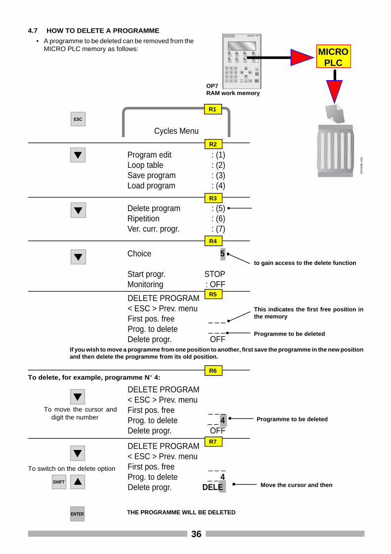
4.7 HOW TO DELETE A PROGRAMME
OP7RAM work memory
• A programme to be deleted can be removed from theMICRO PLC memory as follows:
SIEMENS SIMATIC OP7
F1 F2 F3 F4
K1 K2 K3 K4
7 8 9
4 5 6
1 2 3. 0 +/- SHIFT
INSDEL
HELP ENTER
ACX
ESC
MICROPLC
OP
26
05
-16
0
Cycles Menu
Program edit : (1)Loop table : (2)Save program : (3)Load program : (4)
Delete program : (5)Ripetition : (6)Ver. curr. progr. : (7)
Choice 5
Start progr. STOPMonitoring : OFF
to gain access to the delete function
DELETE PROGRAM< ESC > Prev. menuFirst pos. free _ _ _Prog. to delete _ _ _Delete progr. OFF
R2
R3
R4
R1
R5
ESC
This indicates the first free position inthe memory
Programme to be deleted
If you wish to move a programme from one position to another, first save the programme in the new positionand then delete the programme from its old position.
To delete, for example, programme N ° 4:
To move the cursor anddigit the number
DELETE PROGRAM< ESC > Prev. menuFirst pos. free _ _ _Prog. to delete _ _ 4Delete progr. OFF
Programme to be deleted
To switch on the delete option
DELETE PROGRAM< ESC > Prev. menuFirst pos. free _ _ _Prog. to delete _ _ 4Delete progr. DELE
R6
R7
SHIFT Move the cursor and then
ENTER THE PROGRAMME WILL BE DELETED
37
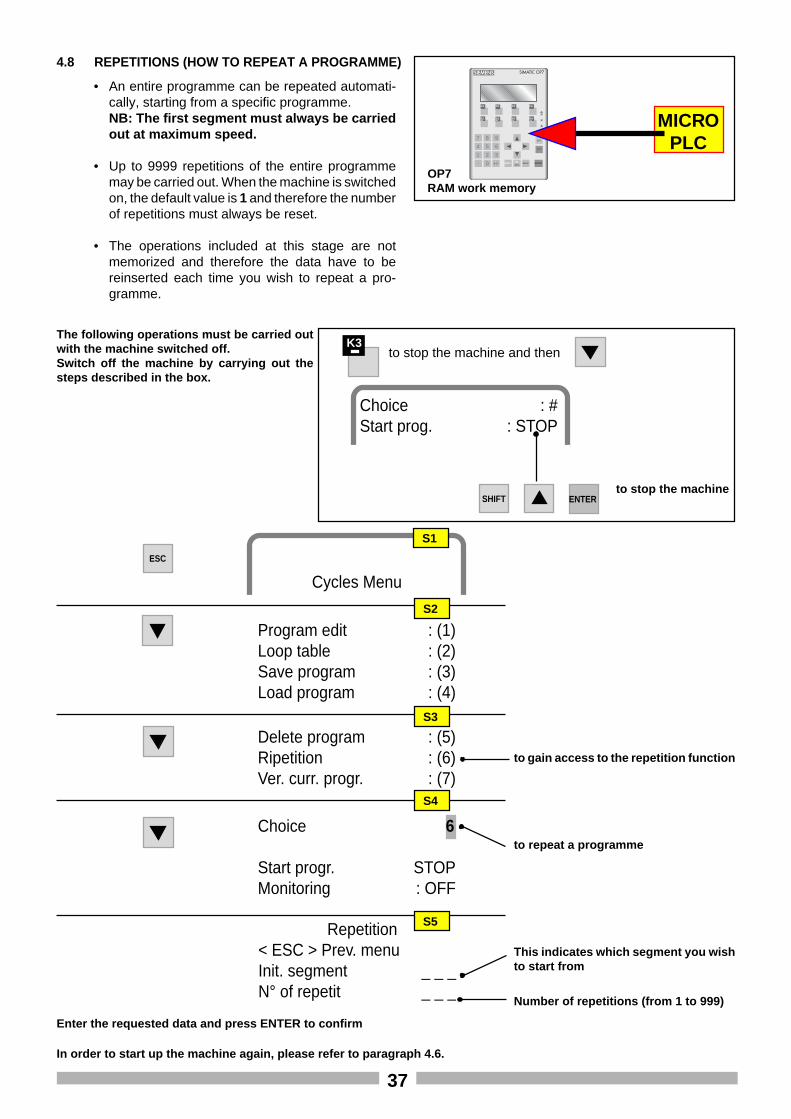
4.8 REPETITIONS (HOW TO REPEAT A PROGRAMME)
• An entire programme can be repeated automati-cally, starting from a specific programme.NB: The first segment must always be carriedout at maximum speed.
• Up to 9999 repetitions of the entire programmemay be carried out. When the machine is switchedon, the default value is 1 and therefore the numberof repetitions must always be reset.
• The operations included at this stage are notmemorized and therefore the data have to bereinserted each time you wish to repeat a pro-gramme.
Cycles Menu
Program edit : (1)Loop table : (2)Save program : (3)Load program : (4)
Delete program : (5)Ripetition : (6)Ver. curr. progr. : (7)
Total repetit : _ _ _Curr. tot. repet : _ _ _Time from init. cycle
hh: mm: ss_ _ _ _ _: _ _ _: _ _ _:
Time from init. segm.hh: mm: ss
_ _ _ _ _: _ _ _: _ _ _:
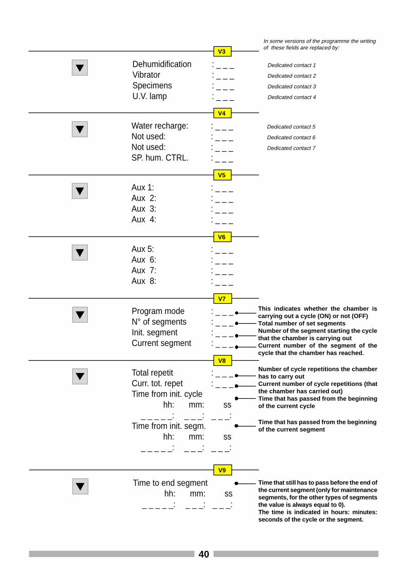
V7
V8
This indicates whether the chamber iscarrying out a cycle (ON) or not (OFF)Total number of set segmentsNumber of the segment starting the cyclethat the chamber is carrying outCurrent number of the segment of thecycle that the chamber has reached.
Number of cycle repetitions the chamberhas to carry outCurrent number of cycle repetitions (thatthe chamber has carried out)Time that has passed from the beginningof the current cycle
Time to end segmenthh: mm: ss
_ _ _ _ _: _ _ _: _ _ _:
V9
Time that still has to pass before the end ofthe current segment (only for maintenancesegments, for the other types of segmentsthe value is always equal to 0).The time is indicated in hours: minutes:seconds of the cycle or the segment.
Time that has passed from the beginningof the current segment
Dedicated contact 1
Dedicated contact 2
Dedicated contact 3
Dedicated contact 4
In some versions of the programme the writingof these fields are replaced by:
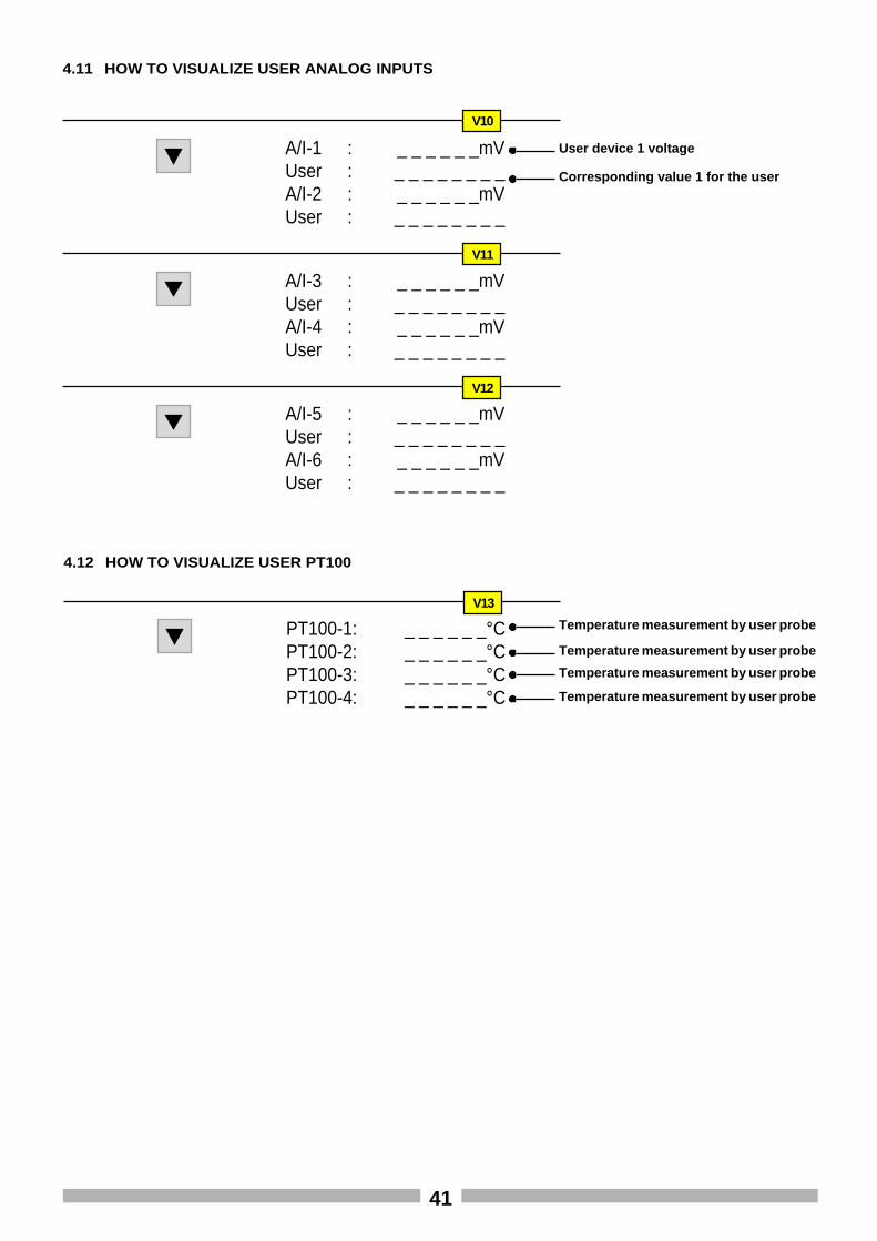
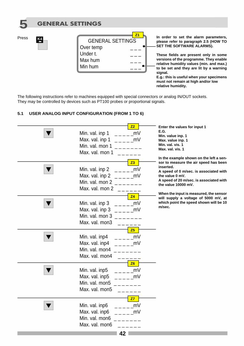
Min. val. inp 1 _ _ _ _ _mVMax. val. inp 1 _ _ _ _ _mVMin. val. mon 1 _ _ _ _ _ _ _Max. val. mon 1 _ _ _ _ _ _
Enter the values for input 1E.G.Min. value inp. 1Max. value inp. 1Min. val. vis. 1Max. val. vis. 1
In the example shown on the left a sen-sor to measure the air speed has beeninserted.A speed of 0 m/sec. is associated withthe value 0 mV.A speed of 20 m/sec. is associated withthe value 10000 mV.
When the input is measured, the sensorwill supply a voltage of 5000 mV, atwhich point the speed shown will be 10m/sec.
Z2
5 GENERAL SETTINGS
PressGENERAL SETTINGS
Over temp _ _ _Under t. _ _ _Max hum _ _ _Min hum _ _ _
In order to set the alarm parameters,please refer to paragraph 2.5 (HOW TOSET THE SOFTWARE ALARMS).
These fields are present only in someversions of the programme. They enablerelative humidity values (min. and max.)to be set and they are lit by a warningsignal.E.g.: this is useful when your specimensmust not remain at high and/or lowrelative humidity.
Z1
Min. val. inp 2 _ _ _ _ _mVMax. val. inp 2 _ _ _ _ _mVMin. val. mon 2 _ _ _ _ _ _ _Max. val. mon 2 _ _ _ _ _ _
Z3
Min. val. inp 3 _ _ _ _ _mVMax. val. inp 3 _ _ _ _ _mVMin. val. mon 3 _ _ _ _ _ _ _Max. val. mon3 _ _ _ _ _ _
Z4
Min. val. inp4 _ _ _ _ _mVMax. val. inp4 _ _ _ _ _mVMin. val. mon4 _ _ _ _ _ _ _Max. val. mon4 _ _ _ _ _ _
Z5
Min. val. inp5 _ _ _ _ _mVMax. val. inp5 _ _ _ _ _mVMin. val. mon5 _ _ _ _ _ _ _Max. val. mon5 _ _ _ _ _ _
Z6
Min. val. inp6 _ _ _ _ _mVMax. val. inp6 _ _ _ _ _mVMin. val. mon6 _ _ _ _ _ _ _Max. val. mon6 _ _ _ _ _ _
Z7
The following instructions refer to machines equipped with special connectors or analog IN/OUT sockets.They may be controlled by devices such as PT100 probes or proportional signals.
K4
5.1 USER ANALOG INPUT CONFIGURATION (FROM 1 TO 6)
43
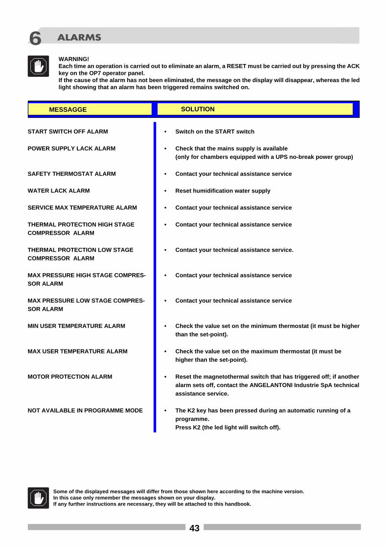
6 ALARMS
MESSAGGE SOLUTION
START SWITCH OFF ALARM
POWER SUPPLY LACK ALARM
SAFETY THERMOSTAT ALARM
WATER LACK ALARM
SERVICE MAX TEMPERATURE ALARM
THERMAL PROTECTION HIGH STAGECOMPRESSOR ALARM
THERMAL PROTECTION LOW STAGECOMPRESSOR ALARM
MAX PRESSURE HIGH STAGE COMPRES-SOR ALARM
MAX PRESSURE LOW STAGE COMPRES-SOR ALARM
MIN USER TEMPERATURE ALARM
MAX USER TEMPERATURE ALARM
MOTOR PROTECTION ALARM
NOT AVAILABLE IN PROGRAMME MODE
• Switch on the START switch
• Check that the mains supply is available(only for chambers equipped with a UPS no-break power group)
• Contact your technical assistance service
• Reset humidification water supply
• Contact your technical assistance service
• Contact your technical assistance service
• Contact your technical assistance service.
• Contact your technical assistance service
• Contact your technical assistance service
• Check the value set on the minimum thermostat (it must be higherthan the set-point).
• Check the value set on the maximum thermostat (it must behigher than the set-point).
• Reset the magnetothermal switch that has triggered off; if anotheralarm sets off, contact the ANGELANTONI Industrie SpA technicalassistance service.
• The K2 key has been pressed during an automatic running of aprogramme.Press K2 (the led light will switch off).
Some of the displayed messages will differ from those shown here according to the machine version.In this case only remember the messages shown on your display.If any further instructions are necessary, they will be attached to this handbook.
WARNING!Each time an operation is carried out to eliminate an alarm, a RESET must be carried out by pressing the ACKkey on the OP7 operator panel.If the cause of the alarm has not been eliminated, the message on the display will disappear, whereas the ledlight showing that an alarm has been triggered remains switched on.