Chu 1 Control Systems for Thermal Vacuum Chambers Benjamin Chu Mentors: Paul Bowerman and Nelson Green Jet Propulsion Laboratory, California Institute of Technology Caltech Student-Faculty Programs NASA Space Grant INTRODUCTION The Jet Propulsion Laboratory (JPL) is a research facility managed by Caltech for NASA that constructs and operates robotic spacecraft for space exploration and scientific research. Prior to launch, all spacecraft hardware needs to be tested in a simulated space environment. These tests are conducted at several locations at JPL, including at the Reliability Assurance Technology Test Laboratory (RATT Lab). To increase the margin of safety when conducting thermal vacuum tests, automated control systems and fail-safes are required to ensure that the sometimes fragile and expensive instruments will not be harmed during testing. A spike in temperature or a loss of vacuum could fatally damage a critical piece of equipment and put the mission behind schedule. OBJECTIVES Controllers and their associated fail-safes that regulate temperature already exist; however, its sensors and actuators need to be installed. A vacuum fail-safe system is to be implemented for one of the vacuum chambers in use in the RATT Lab, shown in Figure 1. Since there are currently no vacuum fail-safe mechanisms installed, the chamber is not yet capable of being “flight” certified. Thus, the chamber is not suited for testing equipment that will one day be used in space. Instead, the chamber is currently used to test non-flight instruments during their development. The addition of the fail-safe will satisfy several of the requirements imposed on chambers prior to flight certification. BACKGROUND Vacuum Systems To simulate a space environment, thermal vacuum chambers are used to mimic the vacuum and temperature environment found in space. Air is pumped out of a sealed chamber to achieve a vacuum. The transition from a viscous fluid to particles in a pipe is defined by the ratio of the mean free path of the molecules to the radius of the pipe, which is a dimensionless number called the Knudsen Number (Kn). In the region where Kn is less than 0.01, the properties of the air are similar to a laminar fluid with viscous effects. In this environment, air is able to be pulled using
Transcript
Chu 1
Control Systems for Thermal Vacuum Chambers
Benjamin Chu
Mentors: Paul Bowerman and Nelson Green
Jet Propulsion Laboratory, California Institute of Technology
Caltech Student-Faculty Programs
NASA Space Grant
INTRODUCTION
The Jet Propulsion Laboratory (JPL) is a research facility managed by Caltech for NASA that
constructs and operates robotic spacecraft for space exploration and scientific research. Prior to
launch, all spacecraft hardware needs to be tested in a simulated space environment. These tests
are conducted at several locations at JPL, including at the Reliability Assurance Technology Test
Laboratory (RATT Lab). To increase the margin of safety when conducting thermal vacuum
tests, automated control systems and fail-safes are required to ensure that the sometimes fragile
and expensive instruments will not be harmed during testing. A spike in temperature or a loss of
vacuum could fatally damage a critical piece of equipment and put the mission behind schedule.
OBJECTIVES
Controllers and their associated fail-safes that regulate temperature already exist; however, its
sensors and actuators need to be installed. A vacuum fail-safe system is to be implemented for
one of the vacuum chambers in use in the RATT Lab, shown in Figure 1. Since there are
currently no vacuum fail-safe mechanisms installed, the chamber is not yet capable of being
“flight” certified. Thus, the chamber is not suited for testing equipment that will one day be used
in space. Instead, the chamber is currently used to test non-flight instruments during their
development. The addition of the fail-safe will satisfy several of the requirements imposed on
chambers prior to flight certification.
BACKGROUND
Vacuum Systems
To simulate a space environment, thermal vacuum chambers are used to mimic the vacuum and
temperature environment found in space. Air is pumped out of a sealed chamber to achieve a
vacuum. The transition from a viscous fluid to particles in a pipe is defined by the ratio of the
mean free path of the molecules to the radius of the pipe, which is a dimensionless number called
the Knudsen Number (Kn). In the region where Kn is less than 0.01, the properties of the air are
similar to a laminar fluid with viscous effects. In this environment, air is able to be pulled using
Chu 2
a simple pump that uses a spinning rotor to induce a pressure difference. A rotary “roughing”
pump first evacuates the chamber to a “rough” vacuum which can reach up to 10-3
Torr (mm
Hg). At higher vacuums, however, the air behaves less like a fluid and more like individual
particles. When Kn is greater than 1, the molecules interact with the walls of the pipe more than
with each other. To reach vacuums as high as 10-10
Torr or “high” vacuum required for lab use,
a second pump is required, the turbomolecular pump. The turbo pump operates like a turbine
and uses momentum transfer to move particles of air. These pumps stall in high pressure viscous
flow. Therefore, the turbo pump is used in conjunction with the “roughing” pump connected in
series [1].
Heat Exchanger Systems
Temperature control is accomplished by using a combination of heaters and liquid nitrogen
(LN2) in conjunction with a heat exchanger plate. To lower the temperature of the chamber, the
thermal control unit will activate one of the solenoid valves on the LN2 lines. This causes cool
gases and eventually liquid to flow through the heat exchanger plate, which cools the plate
through convection. To raise the temperature of the chamber, a voltage will be applied to the
resistance heaters, which will transfer heat to the heat exchanger plates by conduction.
Vacuum and Temperature Sensors
To maintain a constant temperature environment in the thermal vacuum chamber involves the
constant monitoring of the temperature inside the chamber with sensors. Thermocouples are
used to monitor the temperature in the chamber. Thermocouple gauges measure the vacuum up
to “rough” vacuum levels of approximately 10-3
Torr and Bayard-Alpert ionization gauges
measure vacuums up to 10-10
Torr. A Varian vacuum gauge controller is used to measure the
output of both types of gauges and translate it into a vacuum level.
Temperature Control and Fail-safe System
The overall control system that maintains the vacuum and temperature environment in the
chamber consists of three components: the temperature controller, the temperature fail-safe, and
the vacuum fail-safe. There is no vacuum controller because the pumps will try to increase the
vacuum at all times. During normal operation, the temperature controller will attempt to
maintain a preset temperature in the vacuum chamber. Once the temperature at the control point
reaches the set temperature, the temperature controller will cycle the heaters and LN2 valves to
keep the temperature steady. If the system fails and exceeds the temperature presets, the
temperature fail-safe will come into effect to prevent the system from reaching extreme
temperature levels. In the case of excessively high temperatures, power to the heating elements
will be cut. For excessively cold situations, a backup solenoid valve will shut off the flow of
liquid nitrogen to the cooling system.
Vacuum Fail-safe System
Chu 3
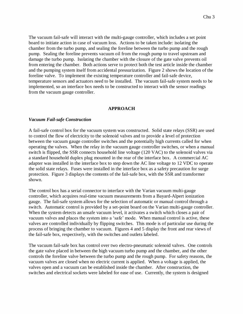
The vacuum fail-safe will interact with the multi-gauge controller, which includes a set point
board to initiate action in case of vacuum loss. Actions to be taken include: isolating the
chamber from the turbo pump, and sealing the foreline between the turbo pump and the rough
pump. Sealing the foreline prevents vacuum oil from the rough pump to travel upstream and
damage the turbo pump. Isolating the chamber with the closure of the gate valve prevents oil
from entering the chamber. Both actions serve to protect both the test article inside the chamber
and the pumping system itself from accidental pressurization. Figure 2 shows the location of the
foreline valve. To implement the existing temperature controller and fail-safe device,
temperature sensors and actuators need to be installed. The vacuum fail-safe system needs to be
implemented, so an interface box needs to be constructed to interact with the sensor readings
from the vacuum gauge controller.
APPROACH
Vacuum Fail-safe Construction
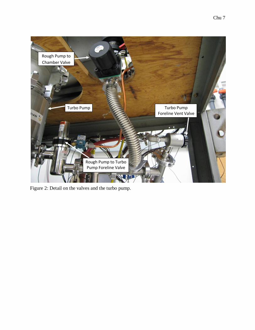
A fail-safe control box for the vacuum system was constructed. Solid state relays (SSR) are used
to control the flow of electricity to the solenoid valves and to provide a level of protection
between the vacuum gauge controller switches and the potentially high currents called for when
operating the valves. When the relay in the vacuum gauge controller switches, or when a manual
switch is flipped, the SSR connects household line voltage (120 VAC) to the solenoid valves via
a standard household duplex plug mounted in the rear of the interface box. A commercial AC
adapter was installed in the interface box to step down the AC line voltage to 12 VDC to operate
the solid state relays. Fuses were installed in the interface box as a safety precaution for surge
protection. Figure 3 displays the contents of the fail-safe box, with the SSR and transformer
shown.
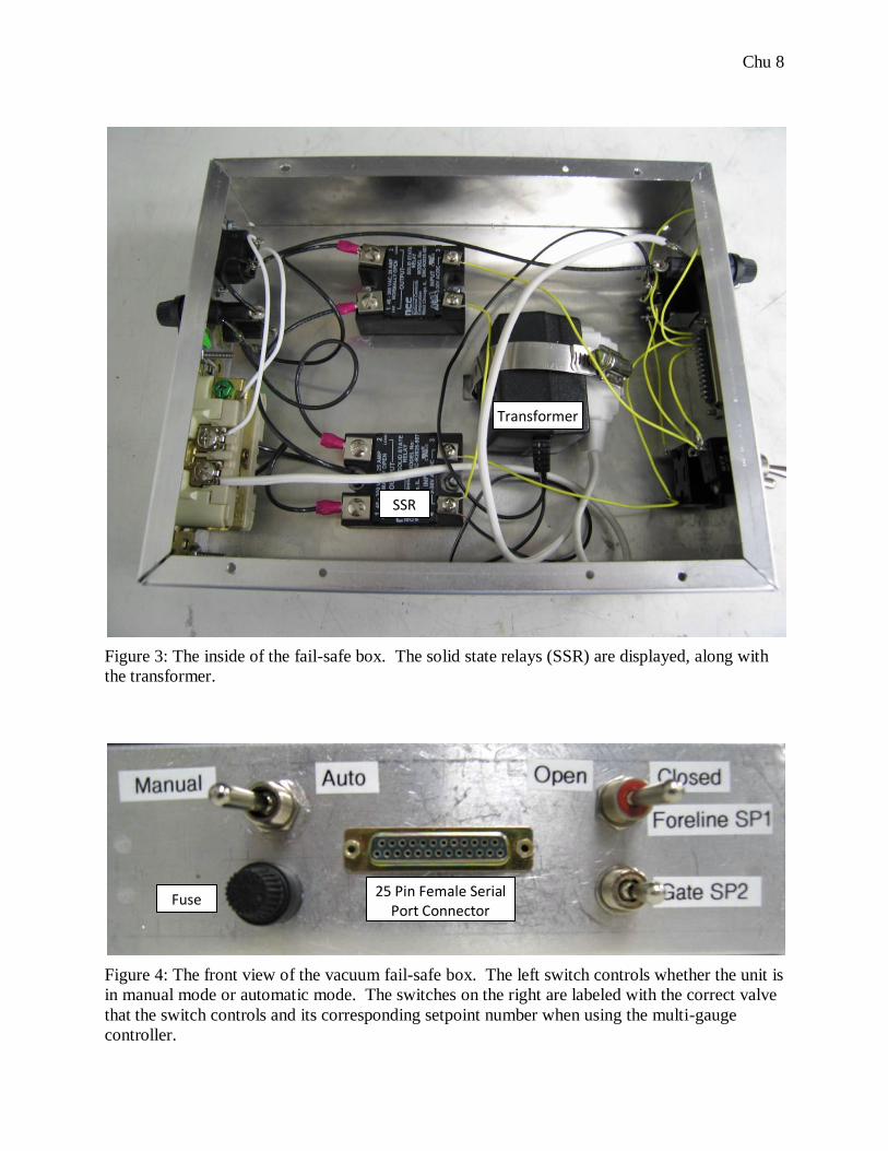
The control box has a serial connector to interface with the Varian vacuum multi-gauge
controller, which acquires real-time vacuum measurements from a Bayard-Alpert ionization
gauge. The fail-safe system allows for the selection of automatic or manual control through a
switch. Automatic control is provided by a set-point board on the Varian multi-gauge controller.
When the system detects an unsafe vacuum level, it activates a switch which closes a pair of
vacuum valves and places the system into a „safe‟ mode. When manual control is active, these
valves are controlled individually by flipping switches. This mode is of particular use during the
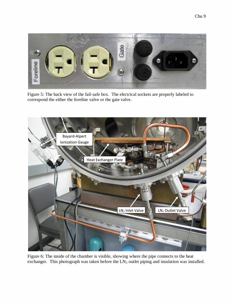
process of bringing the chamber to vacuum. Figures 4 and 5 display the front and rear views of
the fail-safe box, respectively, with the switches and outlets labeled.
The vacuum fail-safe box has control over two electro-pneumatic solenoid valves. One controls
the gate valve placed in between the high vacuum turbo pump and the chamber, and the other
controls the foreline valve between the turbo pump and the rough pump. For safety reasons, the
vacuum valves are closed when no electric current is applied. When a voltage is applied, the
valves open and a vacuum can be established inside the chamber. After construction, the
switches and electrical sockets were labeled for ease of use. Currently, the system is designed
Chu 4
such that other engineers can reset the threshold vacuum value that activates the fail safe
mechanism through interaction with the multi-gauge controller.
Implementation of Temperature Actuators
Solenoid valves that supply liquid nitrogen (LN2) to the temperature exchange plates inside the
vacuum chamber were mounted in the back of the vacuum chamber stand. The design consists
of mounting the solenoid valves using Unistrut channels and their associated clamps.
Specialized Delrin insulators were machined on a lathe so that the copper tubes used to transport
the LN2 may be securely mounted while still remaining thermally insulated from the room
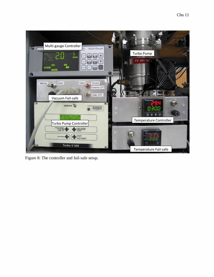
temperature mounting brackets. A pressure relief valve was installed between the two valves to
prevent the dangerous buildup of pressure in the tubing in the case that both solenoid valves are
closed. Polyethylene foam insulation, designed specifically for low temperature applications
was installed to insulate the pipes that deliver the liquid nitrogen to the thermal vacuum chamber
cooling system. This prevents frost from building up on the lines, which can drip water on to
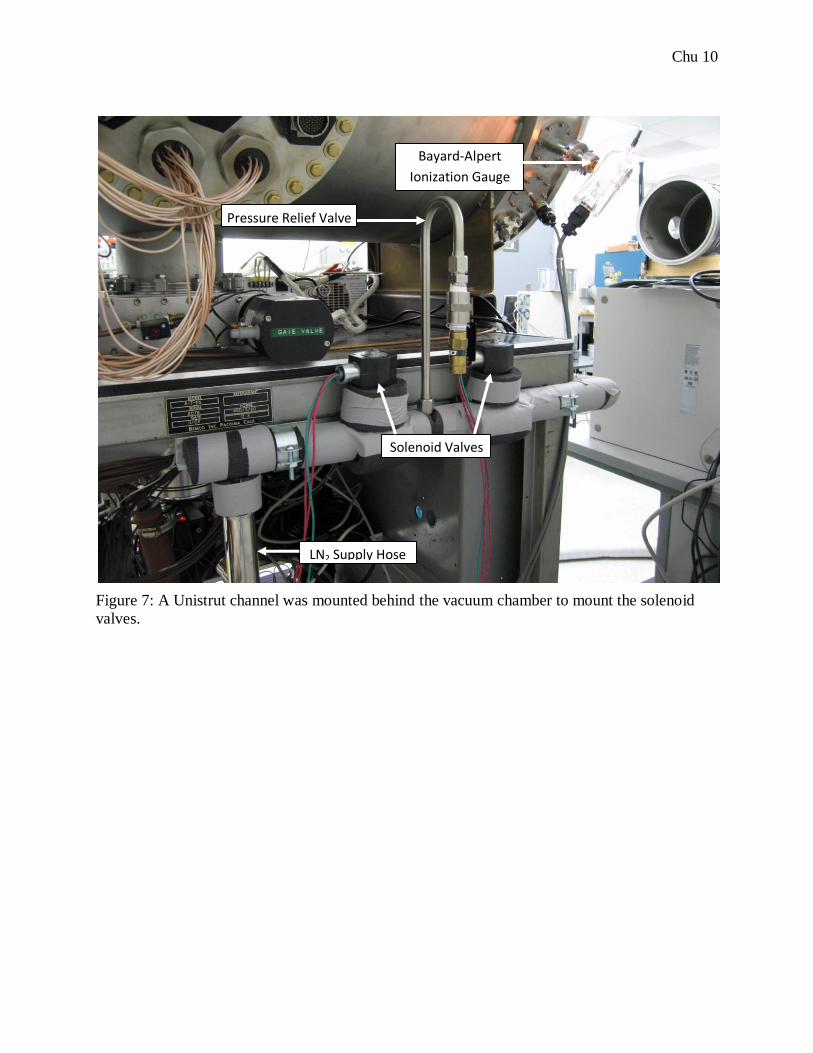
electrical wires. Hoses that supply LN2 were attached to the chamber. One of the solenoid
valves will be used by the primary temperature controller, while the other will be used by the
temperature fail-safe unit. Figures 6 and 7 show the solenoid valve setup.
Three copper heating elements were installed in the chamber. The heating elements are operated
by the temperature controller. Several thermocouple sensors were installed on one of the thermal
exchange plates in the vacuum chamber to measure temperature. These thermocouples were
connected to the temperature controller and fail-safe boxes. The LN2 solenoid valves and heater
set up were integrated with the existing temperature controller and temperature fail-safe. Figure
8 displays the overall control and fail-safe setup.
RESULTS
After construction, the vacuum fail-safe was tested. Nitrogen gas was leaked into the chamber to
simulate a loss of the vacuum. When the vacuum threshold was reached, as measured by the
Bayard-Alpert ion gauge, both the gate valve and foreline valve closed indicating that the fail-
safe units are working. Since the decrease in vacuum was sufficient to turn off the ion gauge, the
system effectively latched in the „safe‟ position. Manual override by an operator was required to
reopen the valves and restart vacuum operations.
The temperature controller and fail-safe system were also tested. To test if the temperature fail-
safe is working, thermocouples were connected to a data acquisition unit to record the
temperature fluctuations over time. The temperature fail-safe was set to a low temperature limit
of -20°C and a high temperature limit of 40°C. To test the fail-safe, the control temperature was
first set to a temperature lower than the low temperature limit (-20°C) to engage the fail-safe.
The temperature in the chamber began to fall after the solenoids opened, allowing LN2 to cool
the chamber. Once the lower temperature limit was reached, the flow of LN2 was halted and the
decrease in temperature began to level off. Once cold temperature failure was simulated and the
fail-safe system shown to be working, the system was tested for another temperature situation.
Chu 5
In the next test, the temperature controller was set to a temperature above the high temperature
limit of the fail-safe (40°C). Given that command, the temperature controller supplied power to
the heaters mounted to the thermal control plate, causing the temperatures to rise. When the
temperature reached the fail-safe set point at 40°C, all power to the thermal control unit was cut
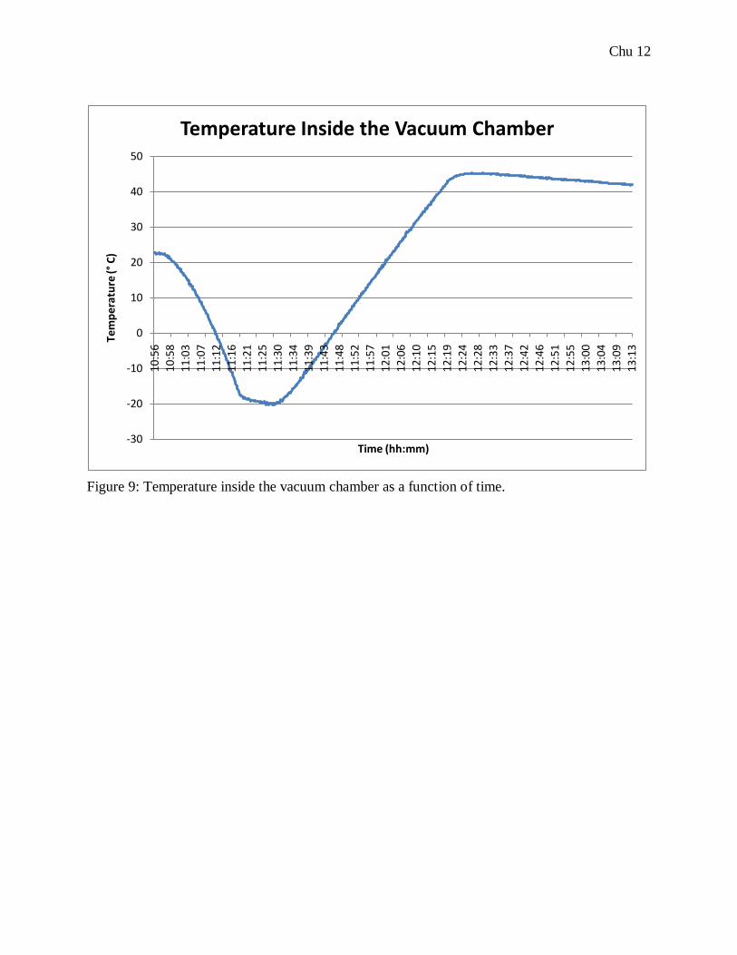
off by the fail-safe unit, shutting off the heaters. The data from this test is displayed in Figure 9.
DISCUSSION
The temperature data record in Figure 9 clearly shows when the fail-safe closed the flow of LN2.
The initial cooling shows a rapid decrease in temperature with time. When the temperature
reached the -20°C fail-safe set point, the temperature flattens drastically. For the hot temperature
fail-safe situation, the temperature plot shows that the temperature continues to increase slightly
above the set point, but the rapid change in temperature was clearly halted. There is some
temperature overshoot after shutting off the temperature actuators. After shutting down the
heaters, the large thermal inertia of the copper plate causes a slight increase in temperature.
Since the thermocouple sensors were attached on the heat exchanger plate, they are sensitive any
residual heat in the heating elements.
Even with a temperature overshoot, the temperature change is small for both heating and cooling
situations and should not pose a problem. To conclude the project, the existing operating
procedure for the thermal vacuum chamber was improved with instructions on how to operate
the fail-safe box so that JPL engineers in the lab will be able to use the system in the future.
ACKNOWLEDGEMENTS
This research was carried out at the Jet Propulsion Laboratory, California Institute of
Technology, and was sponsored by the Caltech Student-Faculty Program, NASA Space Grant,
and the National Aeronautics and Space Administration. Special thanks to my mentors Paul
Bowerman and Nelson Green for supporting me throughout my work. Their guidance was