T: +44 (0)1942 267444 F: +44 (0)1942 267445 E: [email protected]W: www.autoextract.co.uk www.autoextract.co.uk 1 AES’s control units offers a good working environment, adapted to all types of facilities. The right choice of control units is energy-saving and provides the lowest possible noise levels. CONTROL UNITS Control automation encompasses specially adapted and proven components, as well as recommendations for appropriate system selections. In the installation examples on pages 2 through 5, there are suggestions for various solutions to help finding systems to comply with most needs. Exhaust extraction products are presented in various system solutions in the examples. For control of local extractors installations, see the control automation for local extractors.
AES’s control units offers a good working environment, adapted to all types of facilities. The right choice of control units is
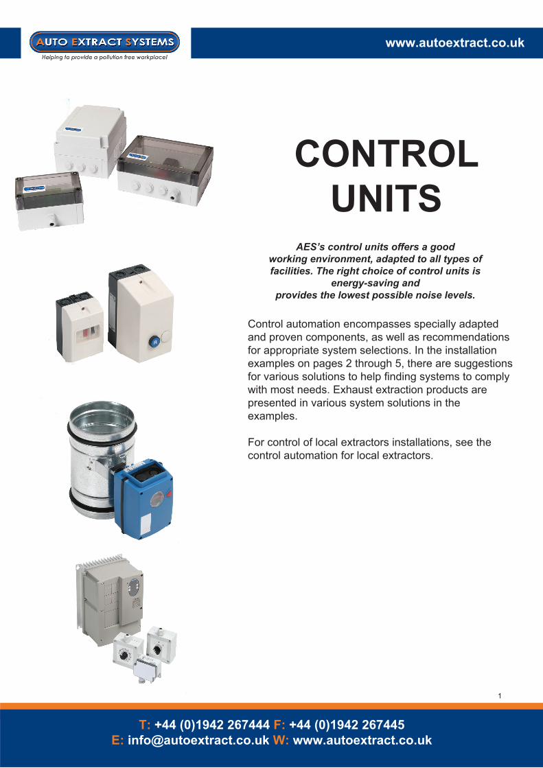
energy-saving and provides the lowest possible noise levels.
CONTROL UNITS
Control automation encompasses specially adapted and proven components, as well as recommendations for appropriate system selections. In the installation examples on pages 2 through 5, there are suggestions for various solutions to help finding systems to comply with most needs. Exhaust extraction products are presented in various system solutions in the examples.
For control of local extractors installations, see the control automation for local extractors.
System 1:11Manual start and stop of fan
The fan is started and stopped manu-ally with protective motor switch SMB.
The protective motor switch has termic magnetic release and a phase failure protection.
Start and stop of fan, with or without speed control
System 1:12Manual speed control of fan started and stopped with an external signal.
The signal to start and stop fan with an external signal from for example a central monitoring system.
The SFC POT potentiometer manually regulates the fan speed control according to your requirements.
System 1:13Manual start and stop of fan two speeds
The fan is started and stopped manu-ally with the rotary switch SFC VSS.
With the rotary switch the fan speed can be switched between 2 preset speeds programmed on the frequency converters display.
System 1:14Manual start and stop of fan as well as demand control of fan speed.
The fan is started and stopped manually with the switch SFC SB.
The frequency converter maintains the negative pressure in the collecting duct using the pressure sensor.
Protective motor
Potentiometer Frequency converter
Rotary Switch
Pressure sensor
Switch
Frequency converter
Frequency converter
1x230/ 3x400 VACSignalkabel/ Signal cable
SMB
SFCSFC POT
SFC VSS SFC
SFCST 300
SFC SB
3X400 VAC
1X230 VAC/ 3X400 VAC
1X230 VAC/ 3X400 VAC
1X230 VAC/ 3X400 VAC
System 2:10Automatic start and stop of fan
Automatic start and stop with a switch placed on the hose reel.
System 2:11Automatic start and stop of fan.
Automatic start and stop with a switch placed on the hose reel or balancing block.
Control unit S 400 is equipped with an adjustable time delay of 0-15 minutes.
System 2:12Automatic start and stop of fan.
Automatic start and stop with a radio switch placed on the balancing block.
Control unit S400 is equipped with an adjustable time delay 0-15 minutes.
Start and stop of fan with contactor.Automatic control, without time delay.
Automatic control, with time delay.
Automatic control, radio transmitted with a time delay.
Trans-former
Connection box
Connection box
Switch
Trans-former
Trans-former
Contactor
Contactor
Contactor
Controlunit
Controlunit
R T
Re- Re-
Control unit
Control unit
R - ReceiverT - Transmit-
R T
1x230/ 3x400 VACSignalkabel/ Signal cable
1X230 VAC/
1X230 VAC/
1X230 VAC/
1X230 VAC
SKO
1X230 VAC
1X230 VAC
SKO
SKO
SKD SKDS
S
S
ASR ASR
ASR AFS 955
S S
S S
APS APS
System 3:10Automatic start and stop of fan.
Start and stop of fan as well as opening and closing of damper is automatic with a switch placed on the hose reel.
Automatic control of fan and damper, without time delay.
Individual damper control, start and stop of fan through a contactor.
Automatic control of fan and damper, with time delay.
Automatic control of fan and damper, radio transmitter with time delay.
System 3:11Automatic start and stop of fan.
Start and stop of fan as well as opening and closing of damper is automatic with a switch placed on the hose reel or balancing block.
Control unit S 400 is equipped with an adjustable time delay 0 - 15 minutes.
System 3:12Automatic start and stop of fan.
Start and stop of fan as well as opening and closing of damper is automatic with a radio transmitted switch placed on the balancing block.
Control unit S 400 is equipped with an adustable time delay 0 - 15 minutes.
Contactor
Contactor
Contactor
Switch Switch
Connection box
Connectionbox
Switch Switch
Re-Switch Switch
Trans-former
Trans-former
Trans-former
Automatic dam- Automatic dam-
Automatic dam- Automatic dam-
Automatic dam- Automatic dam-
Re-
Controlunit
Controlunit
Controlunit
Controlunit
R - ReceiverT - Transmit-
R RT T
1x230/ 3x400 VACSignalkabel/ Signal cable
1X230 VAC/
1X230 VAC/
1X230 VAC/
1X230 VAC
1X230 VAC
1X230 VAC
SKO
SKO
SKO
S 600
S 600
S 600
S 400 S 400
S 400 S 400
SKD
SAS-xxx/24 SAS-xxx/24
SAS-xxx/24 SAS-xxx/24
SAS-xxx/24 SAS-xxx/24
ASR ASR
SKD
ASR AFS 955
APS APS
Individual damper control and control of the fan through a pressure sensor and frequency conver-
Automatic control of the frequency converter and damper, without time delay.
Automatic control of the frequency converter and damper, with time delay.
Automatic control of frequency converters and damper, radio transmitter with time delay.
System 4:10Automatic start and stop of fan.
Start and stop of fan as well as opening and closing of damper is automatic with a switch placed on the hose reel.
The frequency converter maintains a constant negative pressure in the main duct via the pressure sensor.
System 4:11Automatic start and stop of fan.
Start and stop of fan as well as opening and closing of dampers is automatic with a switch placed on the hose reel or balancing block.
The frequency converter maintains a constant negative pressure in the main duct via the pressure sensor.
Control unit S 400 is equipped with an adjustable time delay 0 - 15 minutes.
System 4:12Automatic start and stop of fan
Start and stop of fan as well as opening and closing of damper is automatic with a radio transmitted switch placed on the balancing block.The frequency converter maintains a constant negative pressure in the main duct via the pressure sensor.Control unit S 400 is equipped with an adjustable time delay 0 - 15 minutes. Frequency
FREQUENCY CONVERTER Designed for process ventilation
The SFC frequency converter is designed for variable speed control of e.g. fans. This provides optimal operating economy and the lowest possible noise level. Depending on the number of work stations in operation, the SFC (along with the ST 300 pressure sensor) varies the fan speed and thus evacuates the correct amount of air. Alternatively, manual variable control can be used with the SFC POT potentiometer. The SFC VSS is used if a 2-step control is preferred.Interference filters are included. The enclosure class is IP 21 for built-in applications, alternatively IP 55 for dust- and water protection.AES can supply SFC PROG pre-programmed frequency converters to make it easier to put systems in operation.
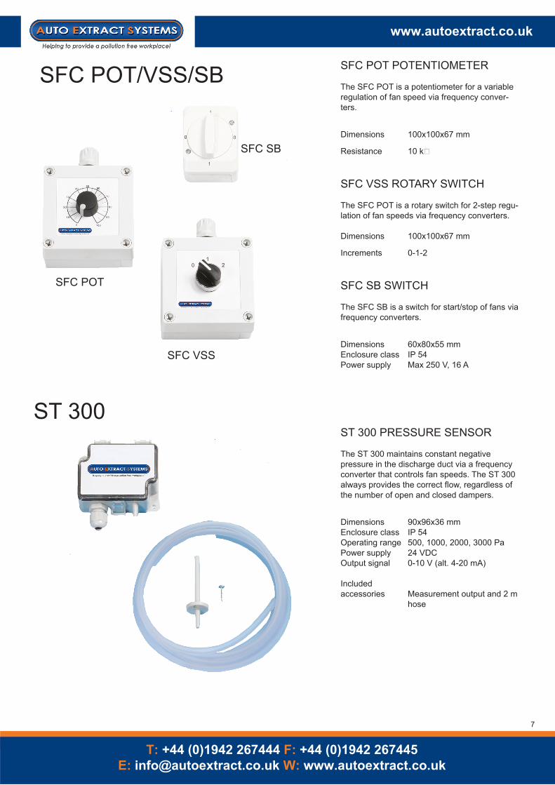
The SFC POT is a potentiometer for a variable regulation of fan speed via frequency conver-ters.
Dimensions 100x100x67 mm
Resistance 10 k�
SFC VSS ROTARY SWITCH
The SFC POT is a rotary switch for 2-step regu-lation of fan speeds via frequency converters.
Dimensions 100x100x67 mm
Increments 0-1-2
SFC SB SWITCH
The SFC SB is a switch for start/stop of fans via frequency converters.
Dimensions 60x80x55 mmEnclosure class IP 54Power supply Max 250 V, 16 A
ST 300 PRESSURE SENSOR
The ST 300 maintains constant negative pressure in the discharge duct via a frequency converter that controls fan speeds. The ST 300 always provides the correct flow, regardless of the number of open and closed dampers.
Dimensions 90x96x36 mmEnclosure class IP 54Operating range 500, 1000, 2000, 3000 PaPower supply 24 VDCOutput signal 0-10 V (alt. 4-20 mA)
Included accessories Measurement output and 2 m hose
The S 400 is used for automatic control of damper motor SAS 24 at terminals 1–4. Fans are normally controlled via the S 600 transformer units. The after-run time for evacua-tion of remaining gases is built into the control unit. The time is set between 0–15 min. The S 400 is supplied with 24 VAC from the S 600 transformer unit.
Dimensions 130x80x77 mmEnclosure class IP 54Primary side 24 VACSecondary side 24 VAC
ACCESSORIES
ASR 865 Switch for hose reel mounted on a hose reel, opens when the hose is pulled down and closes when the hose is fully rolled upp
AFS 955 Switch for balancing block, Single pole switch mounted on a balancing block. Switch is opened when the hose is pulled down and closed when the hose is fully drawn up. Supple-mented with an electrical cable attached on the trolley on the profile rail.
APS 965RC Switch with radio transmitter for profile rail Micro switch mounted on the balancing block. When the hose is pulled down the switch opens and a radiotransmitter
Terminals 1-4 24 V~ For damper SAS-xxx/24. 5-7 Potential-free VX-switch. 8-9 24 V~ supply from S 600. 10-14 Connection sensor (15 V).
The S 600 is used to supply 24 VAC to the S 400 control unit. Control of fan is made via external contactor 230 VAC, via signal from terminals 1 & 2. Frequency converter is con-trolled via the potential-free outputs, terminals 3 and 4. The S 600 can also be used in a custom system with the SKD connection box. The SKD distributes power to dampers and to the switch for automatic start/stop of fans, as well as automatic opening of SAS dampers.
Dimensions 130x180x102 mmEnclosure class IP 54Primary side 230 VACSecondary side 24 VAC (60 VA)
ACCESSORIES
SKD Connection box
ASR 865 Switch for hose reel mounted on a hose reel, opens when the hose is pulled down and closes when the hose is fully rolled upp
S 200/230 CONTROL UNITThe S 200/230 is used for automatic control of damper motor SAS 230 and/or a fan. The after-run time for evacuation of remaining gases is built into the pliers sensor (~30 sec.). For longer after-run times, there is an adjustable timer card (0–15 min. and 0–240 min.) available as an accessory. Single-phase fans (max. 0.75 kW) can be directly controlled via an integrated relay. Other fans are controlled with an external contactor via the same integrated relay, terminals 1–5. Frequency converters are controlled via the potential-free output, terminals 6–8.
Dimensions 180x130x77 mmEnclosure class IP 54Primary side 230 VACSecondary side 230 VAC (Max 10A)
ACCESSORIES
STK 15 Timer card 0-15 minSTK 240 Timer card 0-240 minASR 865 Switch for hose reelAFS 955 Switch for balancing blockAPS 965RC Switch with radio transmitter for profile rail
S 200/24 CONTROL UNITThe S 200/24 is used for automatic control of damper mo-tor SAS 24 and/or a fan. The after-run time for evacuation of remaining gases is built into the pliers sensor (~30 sec.). For longer after-run times, there is an adjustable timer card (0–15 min. and 0–240 min.) available as an accessory.Fans are controlled with external contactors via the integrated relay, terminals 1–5. Frequency converters are controlled via the potential-free output, terminals 6–8.
Dimensions 180x130x77 mmEnclosure class IP 54Primary side 230 VACSecondary side 230 VAC
ACCESSORIES
STK 15 Timer card 0-15 minSTK 240 Timer card 0-240 minASR 865 Switch for hose reelAFS 955 Switch for balancing blockAPS 965RC Switch with radio transmitter for profile rail
The SMB is a 3-pole protective motor switch with thermal-magnetic release and equipped with phase failure protection. The SMB is designed for control and protection of fan motors.
*Self-protecting, pre-fusing not required**Max. pre-fusing when Ik>Icu is 63 A.
SKO CONTACTOR
The SKO is a 3-pole contactor with an overcurrent relay for manual resetting. The overcurrent relay has phase failure protection. It is used with external switches or control.
The SAS is an automatic single-leaf damper for appli-cations where short operating times are necessary.The extremely fast motor opens the damper blade in 7.5 seconds. This entails 95% extraction capacity after 3 seconds.The damper is supplied for air tightness class 1.For other air tightness classes, please contact AES.
Dimensions (motor) 140x100x85 mmMaterial (cowling) PAMaterial (damper housing) Galvanised sheet metalOpening time, 90º 7,5 sTorque 3 NmPower consumption (24 V) 2 VA in operation/ 0 VA not in operationPower consumption (230 V) 5 VA in operation/ 0 VA not in operation