35
1 Automation Instrumentation Summit Castello di Belgioioso, Pavia, 5/6 July 2017 CONTROL VALVE FROM CONTROL LOOP THEORY PERSPECTIVE: An overview Anna Veneroni – SIMECO S.p.A.

1
Automation Instrumentation Summit
Castello di Belgioioso, Pavia, 5/6 July 2017
CONTROL VALVE FROM CONTROL LOOP
THEORY PERSPECTIVE:
An overview
Anna Veneroni – SIMECO S.p.A.

Automation Instrumentation Summit – Castello di Belgioioso, Pavia, 5/6 July 2017 Anna Veneroni – Simeco S.p.A. 2
SUMMARY:
1. The valve as control loop element
- Pressure regulation for gas
- Flow regulation for liquids
2. Characteristic of the valve
- Inherent characteristic
- Installed characteristic
3. The gain of a control valve in a loop
4. Regulator synthesis and tuning
INTRODUCTION
Automation Instrumentation Summit – Castello di Belgioioso, Pavia, 5/6 July 2017 Anna Veneroni – Simeco S.p.A. 3
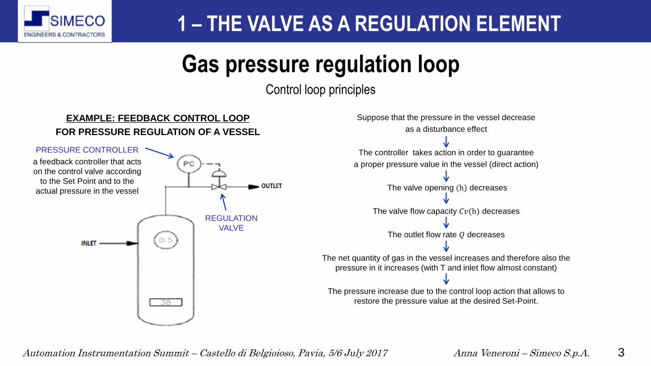
Gas pressure regulation loop Control loop principles
1 – THE VALVE AS A REGULATION ELEMENT
REGULATION
VALVE
PRESSURE CONTROLLER
a feedback controller that acts
on the control valve according
to the Set Point and to the
actual pressure in the vessel
EXAMPLE: FEEDBACK CONTROL LOOP
FOR PRESSURE REGULATION OF A VESSEL
Suppose that the pressure in the vessel decrease
as a disturbance effect
The controller takes action in order to guarantee
a proper pressure value in the vessel (direct action)
The valve opening (h) decreases
The valve flow capacity 𝐶𝑣(h) decreases
The outlet flow rate 𝑄 decreases
The net quantity of gas in the vessel increases and therefore also the
pressure in it increases (with T and inlet flow almost constant)
The pressure increase due to the control loop action that allows to
restore the pressure value at the desired Set-Point.

Automation Instrumentation Summit – Castello di Belgioioso, Pavia, 5/6 July 2017 Anna Veneroni – Simeco S.p.A. 4
FLOW
CONTROLLER
REGULATION
VALVE
Liquid flow regulation loop Control loop principles
1 – THE VALVE AS A REGULATION ELEMENT
THE VALVE AS THE DISSIPATIVE ELEMENT
IN A HYDRAULIC CIRCUIT
In a hydraulic circuit with a flow rate control loop, suppose to have a flow rate
decrease due to a disturbance effect.
The regulator action opens the valve in order to restore the flow rate value in the
circuit to the Set-Point.
As effect of the controller, the flow rate decreases, the output of the controller
increases (reverse action) and the valve opening (h) increases.
Δ𝑝 3 decrease
𝐶𝑣(h) increases
Δ𝑉 3 decreases
Conductance increases
𝐶𝑣(h) of the valve Variable electrical
conductance (NOT linear)
Q increases I increases

Automation Instrumentation Summit – Castello di Belgioioso, Pavia, 5/6 July 2017 Anna Veneroni – Simeco S.p.A. 5
a b
Reference Hydraulic Model
Valve Pressure Profile
1 – THE VALVE AS A REGULATION ELEMENT
Low 𝑞 (the valve is
nearly closed)
Δ𝑝 is concentrated
on the valve
High 𝑞 (the valve is
nearly open)
Δ𝑝 is distribuited
on the lines
p1
p2
p1
p2
p1 = PSource − ∆ppiping a
p2 = PReceiver + ∆ppiping b
Automation Instrumentation Summit – Castello di Belgioioso, Pavia, 5/6 July 2017 Anna Veneroni – Simeco S.p.A. 6
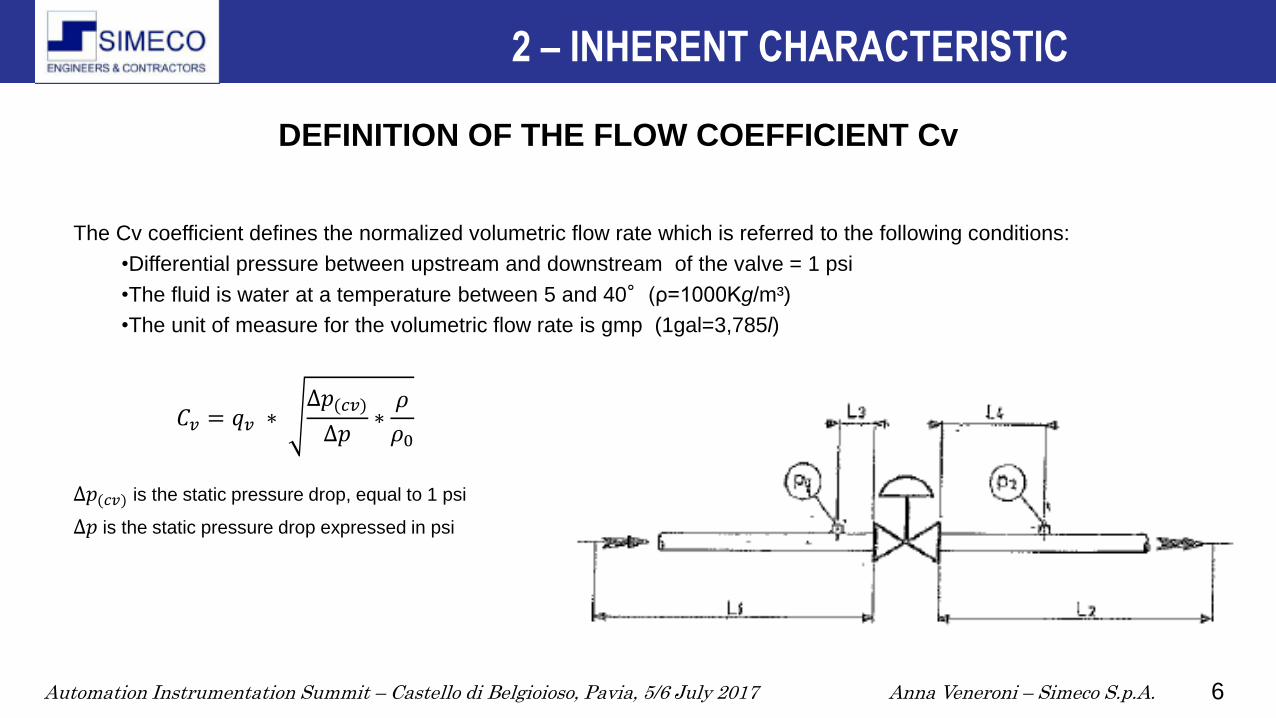
DEFINITION OF THE FLOW COEFFICIENT Cv
The Cv coefficient defines the normalized volumetric flow rate which is referred to the following conditions:
•Differential pressure between upstream and downstream of the valve = 1 psi
•The fluid is water at a temperature between 5 and 40°(ρ=1000Kg/m³)
•The unit of measure for the volumetric flow rate is gmp (1gal=3,785l)
∆𝑝(𝑐𝑣) is the static pressure drop, equal to 1 psi
∆𝑝 is the static pressure drop expressed in psi
2 – INHERENT CHARACTERISTIC
𝐶𝑣 = 𝑞𝑣 ∗ ∆𝑝(𝑐𝑣)
∆𝑝∗𝜌
𝜌0

Automation Instrumentation Summit – Castello di Belgioioso, Pavia, 5/6 July 2017 Anna Veneroni – Simeco S.p.A. 7
2 – INHERENT CHARACTERISTIC
ANSI/ISA–75.01.01–2002 (60534-2-1 Mod) Flow Equations for Sizing Control Valves
Fourth Printing: 15 August 2005
Cv calculation
Sizing equations for incompressible fluids
(Chap. 6 ANSI/ISA–75.01.01–2002 (60534-2-1 Mod)
Turbulent Flow
Non – choked flow
Applicable if ∆𝑃 < 𝐹𝐿𝑃 𝐹𝑃 2(𝑃1 − 𝐹𝐹𝑃𝑉)
Eq. 2 𝐶 =𝑄
𝑁1𝐹𝑃
𝜌1/𝜌0
∆𝑃
Choked flow
Applicable if ∆𝑃 ≥ 𝐹𝐿𝑃 𝐹𝑃 2𝐹𝐿2(𝑃1 − 𝐹𝐹𝑃𝑉)
Eq. 4 𝐶 =𝑄
𝑁1𝐹𝐿𝑃
𝜌1/𝜌0
𝑃1−𝐹𝐹𝑃𝑉

Automation Instrumentation Summit – Castello di Belgioioso, Pavia, 5/6 July 2017 Anna Veneroni – Simeco S.p.A. 8
2 – INHERENT CHARACTERISTIC
Cv calculation
Sizing equations for compressible fluids
(Chap. 7 ANSI/ISA–75.01.01–2002 (60534-2-1 Mod)
Turbulent Flow
Non-choked flow
Applicable if 𝑥 < 𝐹𝛾 ∗ 𝑥𝑇𝑃
Eq. 11a 𝐶 =𝑄
𝑁9𝐹𝑃𝑃1𝑌
𝑀𝑇1𝑍
𝑥
Choked flow
Applicable if 𝑥 ≥ 𝐹𝛾 ∗ 𝑥𝑇𝑃
Eq. 17a 𝐶 =𝑄
0.667𝑁9𝐹𝑃𝑃1
𝑀𝑇1𝑍
𝐹𝛾𝑥𝑇𝑃
Automation Instrumentation Summit – Castello di Belgioioso, Pavia, 5/6 July 2017 Anna Veneroni – Simeco S.p.A. 9
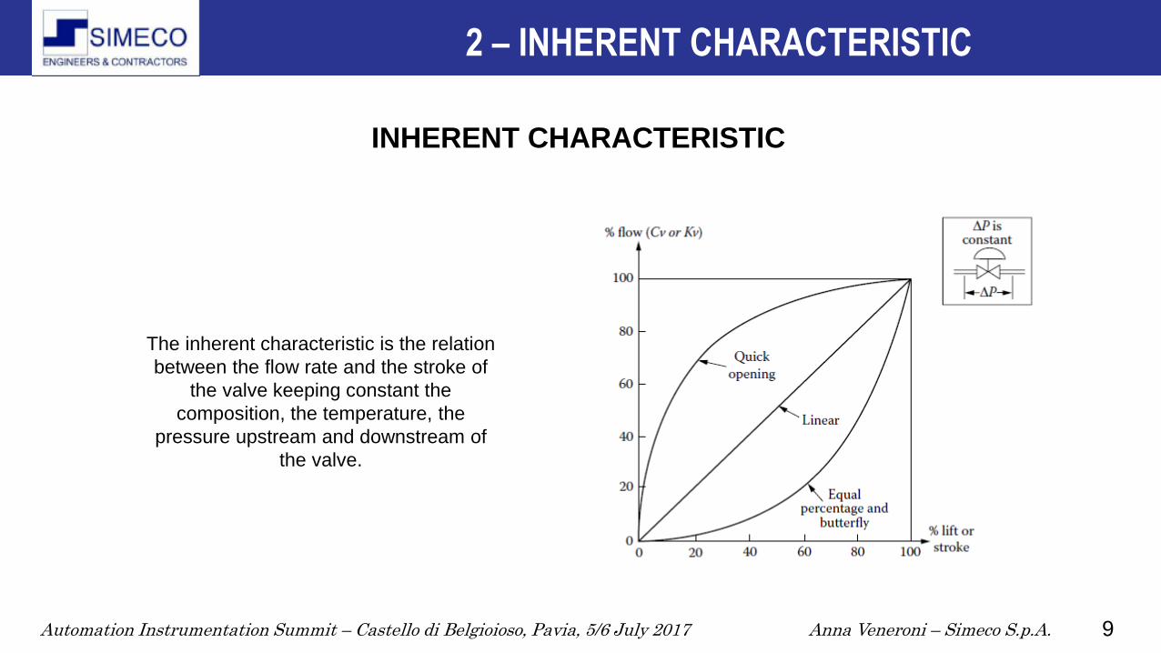
INHERENT CHARACTERISTIC
The inherent characteristic is the relation
between the flow rate and the stroke of
the valve keeping constant the
composition, the temperature, the
pressure upstream and downstream of
the valve.
2 – INHERENT CHARACTERISTIC

Automation Instrumentation Summit – Castello di Belgioioso, Pavia, 5/6 July 2017 Anna Veneroni – Simeco S.p.A. 10
IEC 60534-2-4
Industrial-process control valves – Part 2-4: Flow capacity -
Inherent flow characteristics and rangeability:
It collects all the criteria that shall be applied from the vendors
to define the correct Cv of a valve.
The valve must operate in an appropriate range, with a declared
tolerance. ø =Cv/Cvmax
INHERENT RANGEABILITY
The inherent rangeability of a valve is typically used during the sizing or during the
operating verifications.
It is the range in which both the prescriptions on the slope of the characteristic curve
and the tolerance on the Cv values are applicable.
It does not represent anyway the effective flow rate capacity of the installed valve.
2 – INHERENT CHARACTERISTIC
𝑅 =𝐶𝑣𝑚𝑎𝑥𝐶𝑣𝑚𝑖𝑛
ℎ: 100%
ℎ: 5%

Automation Instrumentation Summit – Castello di Belgioioso, Pavia, 5/6 July 2017 Anna Veneroni – Simeco S.p.A. 11
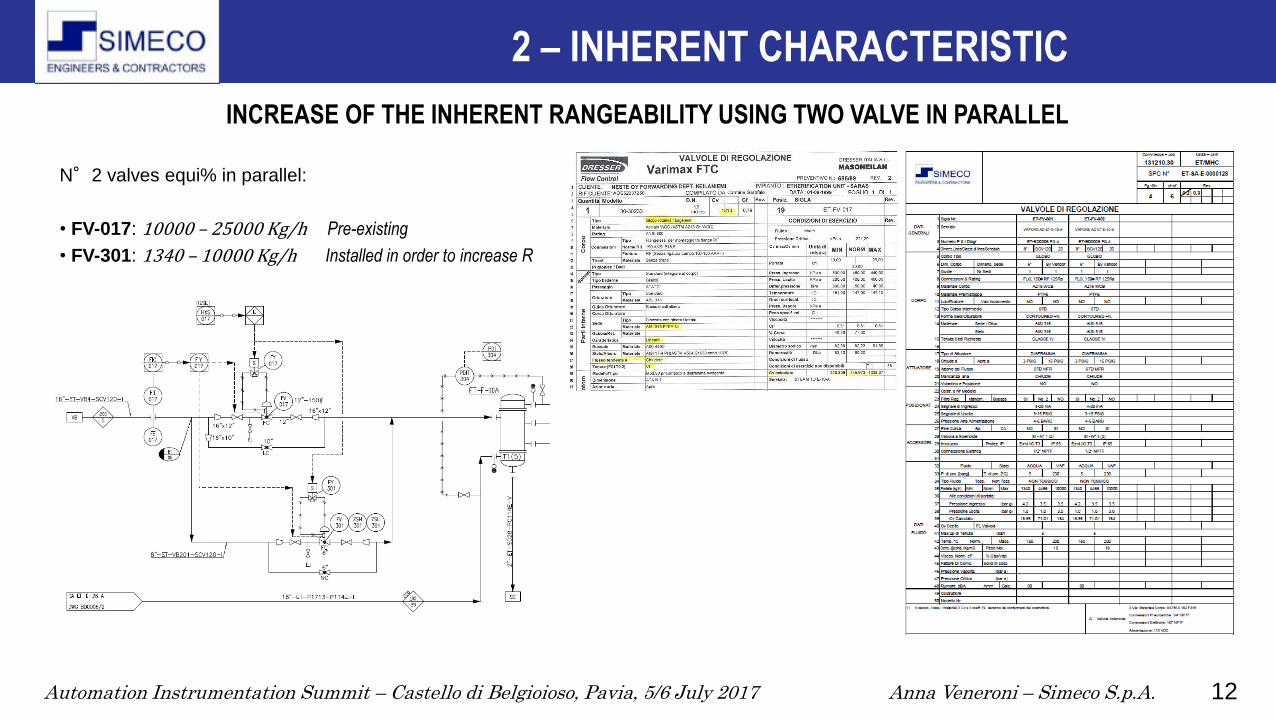
A new and smaller valve has been added in parallel to the existing regulation valve E-10 (FV-017, globe equi%, 12") dedicated to the
regulation of the inlet steam flow rate to the heat exchanger. This new valve is dedicated to the low flow rate regulation (FV-301, globe
equi%, 6").
Applicative example: «Thermal recovery MHC-TAME» for Sarlux
In order to increase the total thermal efficiency of the refinery,
two new heat exchangers have been installed on an existing
etherification plant.
Their function is to heat the etherified gasoline feed in a column
using as hot fluid the GAL available from the near plant MHC.
The GAL flow depends on the operating conditions of the plant
MHC. For this reason the existing heat exchangers, which works
with low pressure steam, shall continue to work though with a
higher range, extending it to low flows.
This condition allows to maintain Set-Point temperature at the
column feed, even if GAL flow rate decreases (for any reason), in
order to optimize the low pressure steam usage.
2 – INHERENT CHARACTERISTIC
INCREASE OF THE INHERENT RANGEABILITY USING TWO VALVE IN PARALLEL
Automation Instrumentation Summit – Castello di Belgioioso, Pavia, 5/6 July 2017 Anna Veneroni – Simeco S.p.A. 12
N°2 valves equi% in parallel:
• FV-017: 10000 – 25000 Kg/h Pre-existing
• FV-301: 1340 – 10000 Kg/h Installed in order to increase R
2 – INHERENT CHARACTERISTIC
INCREASE OF THE INHERENT RANGEABILITY USING TWO VALVE IN PARALLEL
Automation Instrumentation Summit – Castello di Belgioioso, Pavia, 5/6 July 2017 Anna Veneroni – Simeco S.p.A. 13
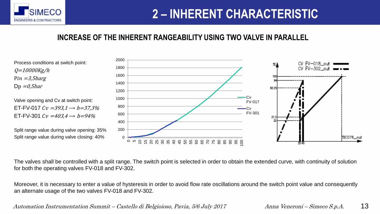
INCREASE OF THE INHERENT RANGEABILITY USING TWO VALVE IN PARALLEL
Process conditions at switch point:
Q=10000Kg/h
P𝑖𝑛 =3,5barg
Dp =0,5bar
Valve opening and Cv at switch point:
ET-FV-017 𝐶𝑣 =393,1 ⟶ h=37,3%
ET-FV-301 𝐶𝑣 =403,4 ⟶ h=94%
Split range value during valve opening: 35%
Split range value during valve closing: 40%
The valves shall be controlled with a split range. The switch point is selected in order to obtain the extended curve, with continuity of solution
for both the operating valves FV-018 and FV-302.
Moreover, it is necessary to enter a value of hysteresis in order to avoid flow rate oscillations around the switch point value and consequently
an alternate usage of the two valves FV-018 and FV-302.
0
200
400
600
800
1000
1200
1400
1600
1800
2000
0 5
10
15
20
25
30
35
40
45
50
55
60
65
70
75
80
85
90
95
10
0
CvFV-017
CvFV-301
2 – INHERENT CHARACTERISTIC
Automation Instrumentation Summit – Castello di Belgioioso, Pavia, 5/6 July 2017 Anna Veneroni – Simeco S.p.A. 14
2 – INSTALLED CHARACTERISTIC
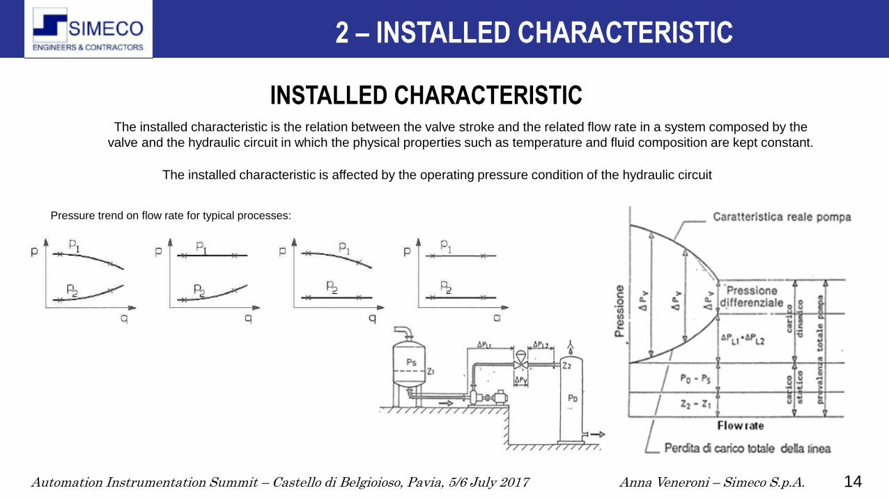
INSTALLED CHARACTERISTIC The installed characteristic is the relation between the valve stroke and the related flow rate in a system composed by the
valve and the hydraulic circuit in which the physical properties such as temperature and fluid composition are kept constant.
Pressure trend on flow rate for typical processes:
The installed characteristic is affected by the operating pressure condition of the hydraulic circuit

Automation Instrumentation Summit – Castello di Belgioioso, Pavia, 5/6 July 2017 Anna Veneroni – Simeco S.p.A. 15
Note:
If the valve resistance decreases in comparison to
total resistance in the system, Dc decreases.
Therefore the flow rate regulation is similar to an on-
off regulation. 5
2 – INSTALLED CHARACTERISTIC
INSTALLED CHARACTERISTIC FOR A LINEAR INHERENT CHARACTERISTIC
𝐷𝑐 =∆𝑃
∆𝑃𝑡

Automation Instrumentation Summit – Castello di Belgioioso, Pavia, 5/6 July 2017 Anna Veneroni – Simeco S.p.A. 16
Note:
Decreasing Dc, the equi-percentage inherent
characteristic becomes a linear installed characteristic
and the minimum controllable flow rate increases.
5
2 – INSTALLED CHARACTERISTIC
INSTALLED CHARACTERISTIC WITH AN EQUIPERCENTAGE INHERENT CHARACTERISTIC
𝐷𝑐 =∆𝑃
∆𝑃𝑡

Automation Instrumentation Summit – Castello di Belgioioso, Pavia, 5/6 July 2017 Anna Veneroni – Simeco S.p.A. 17
2 – CARATTERISTICA INSTALLATA
Comparison between main characteristics
5
If 𝑄 = 𝑄𝑚𝑎𝑥 and 𝑝𝑣𝑎𝑙𝑣𝑒 > 40% 𝑝𝑡𝑜𝑡 , the linear inherent characteristic
allows to obtain the maximum level of linearity in the installed
characteristic.
If 𝑄 = 𝑄𝑚𝑖𝑛 and 𝑝𝑣𝑎𝑙𝑣𝑒 < 25% 𝑝𝑡𝑜𝑡 , the equi% inherent characteristic
allows to obtain the maximum level of linearity in the installed
characteristic.
Valve with high values of specific 𝐶𝑣 (as rotary valves) can be more
easily influenced by the line effects than globe valves. This is because
the rotary valves have a lower p (5÷10 times smaller) at the same
flow rate.
Automation Instrumentation Summit – Castello di Belgioioso, Pavia, 5/6 July 2017 Anna Veneroni – Simeco S.p.A. 18
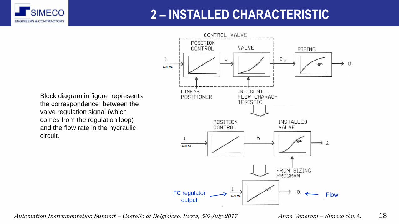
Block diagram in figure represents
the correspondence between the
valve regulation signal (which
comes from the regulation loop)
and the flow rate in the hydraulic
circuit.
FC regulator
output Flow
Kg/h
Kg/h
Kg/h
2 – INSTALLED CHARACTERISTIC

Automation Instrumentation Summit – Castello di Belgioioso, Pavia, 5/6 July 2017 Anna Veneroni – Simeco S.p.A. 19
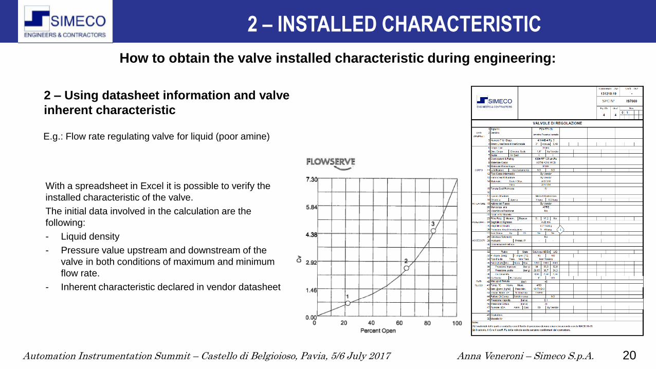
How to obtain the valve installed characteristic during engineering:
E.g.: flow rate regulating valve
for low pressure steam
2 – INSTALLED CHARACTERISTIC
1- Through suitable calculation software for
valve sizing
Automation Instrumentation Summit – Castello di Belgioioso, Pavia, 5/6 July 2017 Anna Veneroni – Simeco S.p.A. 20
With a spreadsheet in Excel it is possible to verify the
installed characteristic of the valve.
The initial data involved in the calculation are the
following:
- Liquid density
- Pressure value upstream and downstream of the
valve in both conditions of maximum and minimum
flow rate.
- Inherent characteristic declared in vendor datasheet
2 – INSTALLED CHARACTERISTIC
E.g.: Flow rate regulating valve for liquid (poor amine)
2 – Using datasheet information and valve
inherent characteristic
How to obtain the valve installed characteristic during engineering:

Automation Instrumentation Summit – Castello di Belgioioso, Pavia, 5/6 July 2017 Anna Veneroni – Simeco S.p.A. 21
28
29
30
31
32
33
34
35
36
28
29
30
31
32
33
34
35
36
12
00
14
64
17
28
19
92
22
56
25
20
27
84
30
48
33
12
35
76
38
40
41
04
43
68
q [
Kg
/h]
Dp/q
pin
pout
Knowing upstream and downstream valve pressure in both conditions of maximum and minimum flow rate, it is possible to select
the most appropriate pressure trend between typical ones and interpolate the datasheet pressure values accordingly.
0,00
1,00
2,00
3,00
4,00
5,00
6,00
7,00
0 510
15
20
25
30
35
40
45
50
55
60
65
70
75
80
85
90
95
10
0
h [
%]
Cv/h Inherent characteristis
Cv
2 – INSTALLED CHARACTERISTIC
Here below are visible the inherent characteristic and the Δp= pin – pout trend entered in calculation sheet:
How to obtain the valve installed characteristic during engineering:

Automation Instrumentation Summit – Castello di Belgioioso, Pavia, 5/6 July 2017 Anna Veneroni – Simeco S.p.A. 22
03,4
56,9
10
,35
13
,817
,25
20
,724
,15
27
,631
,05
34
,537
,95
41
,444
,85
48
,351
,75
55
,258
,65
62
,165
,55
69
72
,45
75
,979
,35
82
,886
,25
89
,793
,15
96
,6
0
500
1000
1500
2000
2500
3000
3500
4000
4500
5000
q [Kg/h]/ h [%] Caratteristica Installata
Q
2 – INSTALLED CHARACTERISTIC
The installed rangeability is:
𝑅 =𝑄 100%
𝑄 5%= 5000
300 = 16.6
How to obtain the valve installed characteristic during engineering:
𝐷𝑐 =∆𝑃
∆𝑃𝑡
How to calculate the installed characteristic:
- Select a q value in the range
- Read the corresponding p value from plot p/q
- Calculate Cv from the equation 𝐶𝑣 =𝑞𝑣
0,865∗∆𝑃
𝜌/𝜌0
- Read the corresponding valve stroke value h from
inherent characteristic
- Plot (q, h)
- Select another q value in the range and repeat the
steps
𝐷𝑐 = 0,31
Automation Instrumentation Summit – Castello di Belgioioso, Pavia, 5/6 July 2017 Anna Veneroni – Simeco S.p.A. 23
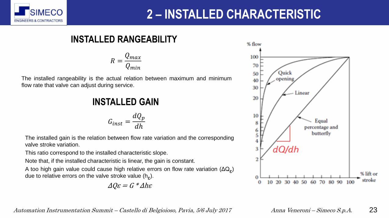
INSTALLED RANGEABILITY
The installed rangeability is the actual relation between maximum and minimum
flow rate that valve can adjust during service.
INSTALLED GAIN
The installed gain is the relation between flow rate variation and the corresponding
valve stroke variation.
This ratio correspond to the installed characteristic slope.
Note that, if the installed characteristic is linear, the gain is constant.
A too high gain value could cause high relative errors on flow rate variation (ΔQɛ)
due to relative errors on the valve stroke value (hɛ).
ΔQɛ = G * Δhɛ
2 – INSTALLED CHARACTERISTIC
𝑅 =𝑄𝑚𝑎𝑥𝑄𝑚𝑖𝑛
𝐺𝑖𝑛𝑠𝑡 =𝑑𝑄𝑝𝑑ℎ

Automation Instrumentation Summit – Castello di Belgioioso, Pavia, 5/6 July 2017 Anna Veneroni – Simeco S.p.A. 24
The valve model
Can be approximated by linearization
around every equilibrium flow rate point,
3 – VALVE GAIN IN A CONTROL LOOP Introduction to the control theory….
MODEL LINEARIZATION AROUND THE OPERATING POINT
Applying
Laplace Transform
On linearized system:
If we consider a process operating plant in stationary conditions we can assume that:
the pressure drop of the valve (Δp(t)) is constant, the valve flow rate (Q(t)) is constant and equal to its nominal value 𝑄 and therefore the valve
stroke is equal to the corresponding ℎ in valve installed characteristic.
In these conditions, if the flow rate has very small variations around the nominal value, the installed characteristic of the valve can be
approximated to the straight line with the same slope of the installed characteristic in that point.
𝑄 + 𝛿𝑄 𝑡 = ℎ + 𝐺𝑖𝑛𝑠𝑡 ℎ + δℎ 𝑡
𝑄(𝑡) = 𝑄𝑐 𝑖𝑛𝑠𝑡(ℎ 𝑡 )
Q s = 𝐺𝑖𝑛𝑠𝑡 ℎ ∗ ℎ 𝑠
Automation Instrumentation Summit – Castello di Belgioioso, Pavia, 5/6 July 2017 Anna Veneroni – Simeco S.p.A. 25
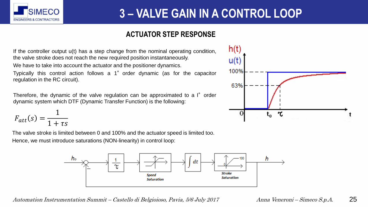
ACTUATOR STEP RESPONSE
If the controller output u(t) has a step change from the nominal operating condition,
the valve stroke does not reach the new required position instantaneously.
We have to take into account the actuator and the positioner dynamics.
Typically this control action follows a 1°order dynamic (as for the capacitor
regulation in the RC circuit).
Therefore, the dynamic of the valve regulation can be approximated to a I°order
dynamic system which DTF (Dynamic Transfer Function) is the following:
The valve stroke is limited between 0 and 100% and the actuator speed is limited too.
Hence, we must introduce saturations (NON-linearity) in control loop:
3 – VALVE GAIN IN A CONTROL LOOP
𝐹𝑎𝑡𝑡 𝑠 =1
1 + 𝜏𝑠
Automation Instrumentation Summit – Castello di Belgioioso, Pavia, 5/6 July 2017 Anna Veneroni – Simeco S.p.A. 26
3 – VALVE GAIN IN A CONTROL LOOP
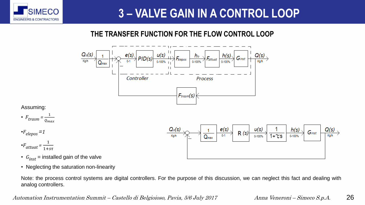
THE TRANSFER FUNCTION FOR THE FLOW CONTROL LOOP
Note: the process control systems are digital controllers. For the purpose of this discussion, we can neglect this fact and dealing with
analog controllers.
Assuming:
• Ftrasm = 1
𝑄𝑚𝑎𝑥
•Felepos =1
•Fattuat = 1
1+𝑠𝜏
• Ginst = installed gain of the valve
• Neglecting the saturation non-linearity
Automation Instrumentation Summit – Castello di Belgioioso, Pavia, 5/6 July 2017 Anna Veneroni – Simeco S.p.A. 27
GENERAL THEORY CONSIDERATION FOR REGULATOR SYNTHESIS
Even if the installed characteristic is nearly linear, the control valve is always a non-linear system.
This is basically due to the control valve 𝐶𝑣 max limitation.
This behavior can be modeled by a saturation.
This non-linearity can be approached using the non-linear control theory.
For historical and practical reasons in the process control it is widespread the usage of linear controllers.
So the regulator synthesis is the construction of a proper Controller Transfer Function.
In addition, it is a very common practice to use standard Controller Transfer Functions (typically PID
regulators) and to define their parameters by tuning.
Then, the actuator saturation is managed taking into account «ad hoc» techniques called ANTI WIND-UP.
4 – REGULATOR SYNTHESIS
Automation Instrumentation Summit – Castello di Belgioioso, Pavia, 5/6 July 2017 Anna Veneroni – Simeco S.p.A. 28
Appling Laplace transformation:
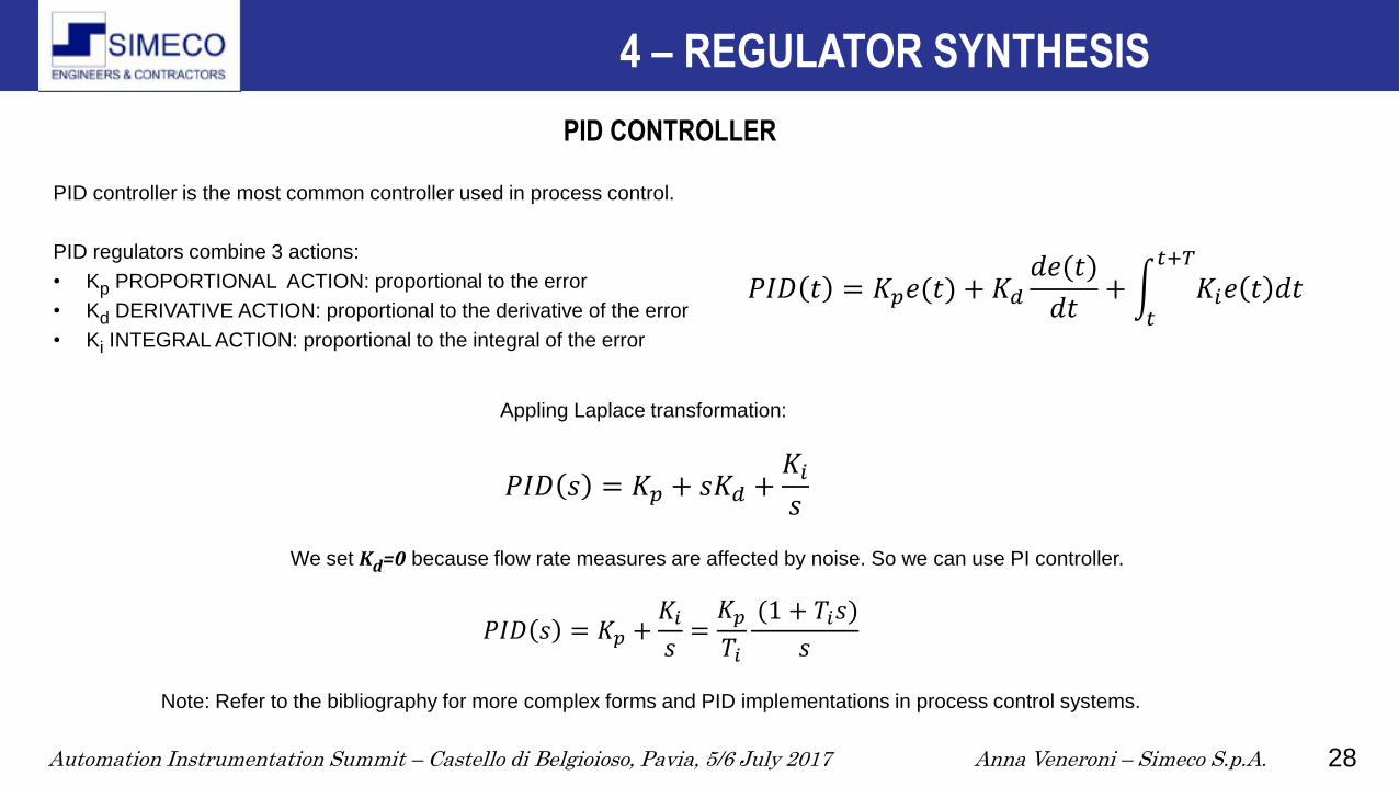
PID CONTROLLER
PID controller is the most common controller used in process control.
PID regulators combine 3 actions:
• Kp PROPORTIONAL ACTION: proportional to the error
• Kd DERIVATIVE ACTION: proportional to the derivative of the error
• Ki INTEGRAL ACTION: proportional to the integral of the error
4 – REGULATOR SYNTHESIS
We set Kd=0 because flow rate measures are affected by noise. So we can use PI controller.
Note: Refer to the bibliography for more complex forms and PID implementations in process control systems.
𝑃𝐼𝐷 𝑡 = 𝐾𝑝𝑒(𝑡) + 𝐾𝑑𝑑𝑒(𝑡)
𝑑𝑡+ 𝐾𝑖𝑒 𝑡 𝑑𝑡
𝑡+𝑇
𝑡
𝑃𝐼𝐷 𝑠 = 𝐾𝑝 + 𝑠𝐾𝑑 +𝐾𝑖𝑠
𝑃𝐼𝐷 𝑠 = 𝐾𝑝 +𝐾𝑖𝑠=𝐾𝑝𝑇𝑖
(1 + 𝑇𝑖𝑠)
𝑠

Automation Instrumentation Summit – Castello di Belgioioso, Pavia, 5/6 July 2017 Anna Veneroni – Simeco S.p.A. 29
In order to identify the right parameters of the PID controller to guarantee the stability of the process, it is necessary that the
parameters of the process transfer function are almost constant.
The maximum variation of the process gain (ratio valve flow rate/controller output) must be limited.
Empirical value: max 4:1
CONSIDERATIONS ON THE GAIN OF THE INSTALLED VALVE
4 – REGULATOR SYNTHESIS
If the gain exceed this empirical value, will be necessary
have a PID regulator with variable parameters to ensure
a robust control.
Anyway, for the valve system is required that Ginst(q(t)) is
as much as possible constant.
For this reason the valve gain is required to be within a
specific range. For example 0,75÷3 or 0,5÷2 that
comply to general rule:
𝐺𝑖𝑛𝑠𝑡 𝑚𝑎𝑥𝐺𝑖𝑛𝑠𝑡 𝑚𝑖𝑛
< 4

Automation Instrumentation Summit – Castello di Belgioioso, Pavia, 5/6 July 2017 Anna Veneroni – Simeco S.p.A. 30
LOOP GAIN AND TRANSFER FUNCTION Q(s)/Q0(s)
4 – REGULATOR SYNTHESIS
𝐿 𝑠 =𝐺𝑖𝑛𝑠𝑡𝑄𝑚𝑎𝑥
𝐾𝑝
𝑇𝑖
(1 + 𝑇𝑖𝑠)
1 + 𝜏𝑠 𝑠
𝐹 𝑠 =𝐿(𝑠)
1 + 𝐿(𝑠)=
(1 + 𝑇𝑖𝑠)
𝛼𝑠2 + 𝛽𝑠 + 1

Automation Instrumentation Summit – Castello di Belgioioso, Pavia, 5/6 July 2017 Anna Veneroni – Simeco S.p.A. 31
THE STATIC GAIN OF THE SYSTEM Q(0)/Q0(0)
In time domain, for a Set-Point step variation, after a theoretically infinite time period, Q(s)= 𝑄0(s),
so the error between the Set-Point and the process variable (i.e. the flow rate) is zero.
4 – REGULATOR SYNTHESIS
From a mathematical point of view s=jω=j2πf where f is the frequency.
So, if the signal frequency f goes to zeros the transfer function F(s) goes to one.
If f ⟶ 0 then 𝐹(𝑠) ⟶ 1
F(0)=1
𝐹 𝑠 =(1 + 𝑇𝑖𝑠)
𝛼𝑠2 + 𝛽𝑠 + 1

Automation Instrumentation Summit – Castello di Belgioioso, Pavia, 5/6 July 2017 Anna Veneroni – Simeco S.p.A. 32
REGULATOR TUNING
4 – REGULATOR SYNTHESIS
If the time constant of the actuator t is available,
it is possible to choice Ti=t
Hence, F(s) results to be a low-pass filter with gain=1 and critical
pulsation:
ωc = 2πT
(Hz)
It is possible to choose Kp in order to force the desired critical pulsation wc and the response time of the system, of course, within the actuator
valve and process limit.
𝐿 𝑠 = 𝐾(1+𝑇𝑖𝑠)
1+𝜏𝑠 𝑠=𝐾
𝑠 in which 𝐾 =
𝐺𝑖𝑛𝑠𝑡
𝑄𝑚𝑎𝑥
𝐾𝑝
𝑇𝑖
𝐹 𝑠 =1
1+𝑇𝑠 in which 𝑇 =
1
𝐾
𝑃𝐼 𝑠 =𝐾𝑝𝑇𝑖
(1 + 𝑇𝑖𝑠)
𝑠

Automation Instrumentation Summit – Castello di Belgioioso, Pavia, 5/6 July 2017 Anna Veneroni – Simeco S.p.A. 33
TUNING METHODS FOR PID CONTROLLER
A ) Tuning methods based on the experimentally process open loop
response to Set-Point step variation
If the process response can be approximated to a I°order system,
we can use:
• Tangent method
• Areas method
• Ziegler-Nichols in open loop
• Cohen-Coon
• Internal Model Control (IMC)
B ) Tuning method based on the experimentally closed loop response
analysis on the system
• Ziegler-Nichols in closed loop
4 – REGULATOR SYNTHESIS
Automation Instrumentation Summit – Castello di Belgioioso, Pavia, 5/6 July 2017 Anna Veneroni – Simeco S.p.A. 34
Bibliography:
Béla G. Liptàk, Instrument Engineers’ Handbook - Process Control and Optimization - 4th Edition, CRC Press Taylor &
Francis Group, 2006
P. Muroni, Valvole di regolazione per processi industriali - GISISERVIZI.srl, Milano, 2001
METSO, Flow Control Manual – 6th Edition, METSO AUTOMATION INC., Vantaa, Finland, 2011
F. G. Shinskey: Process Control Systems – 4th Edition, McGraw-Hill,1996
P. Bolzern, R. Scattolini, N. Schiavoni, Fondamenti di controlli automatici – 3° Edizione - McGraw-hill, 2008
ANSI/ISA-75.01.01-2012 (60534-2-1 MOD) Industrial-Process Control Valves - Part 2-1: Flow capacity - Sizing equations
for fluid flow under installed conditions
IEC 60534-2-4, Industrial-process control valves - Part 2-4: Flow capacity - Inherent flow characteristics and rangeability,
Edizione 2.0, 5/13/2009
BIBLIOGRAPHY

Automation Instrumentation Summit – Castello di Belgioioso, Pavia, 5/6 July 2017 Anna Veneroni – Simeco S.p.A. 35
THANK YOU FOR YOUR ATTENTION
Simeco S.p.A.
Via Romilli, 22 - 20139 Milano (Italy)
tel. +39.02.99298.1
fax +39.02.56.91.424
www.simecomilano.it


