68
ControlEdge PLC EtherNet/IP User's Guide RTDOC-X548-en-161A March 2020 Release 161 ControlEdge PLC

ControlEdge PLC
EtherNet/IP User's Guide
RTDOC-X548-en-161A
March 2020
Release 161
ControlEdge PLC

DISCLAIMERThis document contains Honeywell proprietary information.Information contained herein is to be used solely for the purposesubmitted, and no part of this document or its contents shall bereproduced, published, or disclosed to a third party without theexpress permission of Honeywell International Sàrl.
While this information is presented in good faith and believed to beaccurate, Honeywell disclaims the implied warranties ofmerchantability and fitness for a purpose and makes no expresswarranties except as may be stated in its written agreement with andfor its customer.
In no event is Honeywell liable to anyone for any direct, special, orconsequential damages. The information and specifications in thisdocument are subject to change without notice.
Copyright 2020 - Honeywell International Sàrl
2

3
CONTENTSContents 3
Chapter 1 - About this guide 5
Chapter 2 - Overview 9
Chapter 3 - Planning and Designing EtherNet/IP 11Tested EtherNet/IP devices 11
EtherNet/IP implementation architecture and topologies 13
Device Level Ring (DLR) 15
STAR with Stratix switch or MOXA switch 17
Linear (Broken Ring) on Non-redundant CPM 20
Common network for multiple CPM 21
Network usage guidelines and recommendations 22
Chapter 4 - Configuration 25Configuring EtherNet/IP Client 26
Binding EtherNet/IP Client to an Ethernet port 27
Registering device types 28
Editing device types 34
Configuring EtherNet/IP devices using EDS files 36
Configuring generic EtherNet/IP devices 44
Scaling support for generic device 48
Input and Output parameter of Rockwell 1756 and 1794 series I/Omodules 49
Configuring communication with third-party controllers 53
Configuring communication with C300/UOC 53
Configuring communication with ControlLogix controllers 54
Configuring EtherNet/IP Server 55
Binding EtherNet/IP Server to an Ethernet port 55
Contents

Selecting EtherNet/IP for variables 55
Chapter 5 - EtherNet/IP I/O Behavior during switchover 57
Chapter 6 - Diagnostic 59Configuring DLR network status 59
Viewing EtherNet/IP device diagnostics 59
EtherNet/IP device error codes 62
Appendix A - Status codes 65
Notices 66
4
Contents

CHAPTER
1 ABOUT THIS GUIDE
This document provides an overview of the use of EtherNet/IP™communication with ControlEdge™ 900 Controller and offerspractical guidance to perform a successful integration of EtherNet/IPwith ControlEdge™ 900 Controller.
Revision history
Revision Date Description
A March 2020 Initial release of this document
Intended audience
This documentation is intended for the following audience: Users whoplan, install, configure, operate, or maintain ControlEdge™ 900controllers running the eCLR (IEC 61131-3) execution environment.
Prerequisite skills
Knowledge of SCADA systems and experience of working in aMicrosoft Windows environment are required.
Introduction to ControlEdge Technology
Item Description
ControlEdge PLC ControlEdge 900 controllers running the eCLR (IEC 61131-3) execution environment with PLC software optionsconfigured with ControlEdge Builder.
ControlEdge RTU ControlEdge 2020 controllers running the eCLR (IEC 61131-3) execution environment with RTU software optionsconfigured with ControlEdge Builder.
ControlEdge UOC ControlEdge 900 controllers running the Honeywell controlexecution environment (CEE) configured with ExperionControl Builder.
5

Special terms
The following table describes some commonly used industry-wideand Honeywell-specific terminology:
Terminology Description
Adapter A communication device which connects to the EtherNet/IPnetwork to serve data from a set of devices or modulesunderneath it. Adapter typically supports I/O connectivity fromScanners via implicit EtherNet/IP connections.
Assembly A set of data passed between a Originator and a Target after animplicit I/O connection has been established on an EtherNet/IPnetwork.
CIP Common Industrial Protocol
EDS Electronic Data Sheet. A text file which specifies all the propertiesof an EtherNet/IP device necessary for a Scanner module tocommunicate with it. EDS files may be used in the first step ofcreating an I/O module or device type for interfacing to anEtherNet/IP device.
IP Internet Protocol
Originator Originator is the controller that initiates any data exchange withEtherNet/IP devices on the EtherNet/IP network.
RPI Requested Packet Interval. The repetitive interval by whichassemblies are periodically transported over EtherNet/IP I/Oconnections between Producer and Consumer.
Scanner A device which connects to the EtherNet/IP network to act as aclient of other EtherNet/IP connected devices. ControlEdge 900Controller acts as EtherNet/IP Scanner. It connects to andexchanges data with Adapters of Modular I/O stations, directlyconnected devices and Rockwell AB ControLogix controllers.
Target Target is the EtherNet/IP device that address any data requestsgenerated by the controller.
TCP Transport Control Protocol
UDP User Datagram Protocol
ODVA Open DeviceNet Vendors Association
6
Chapter 1 - About this guide

7
Related documents
The following list identifies publications that may contain informationrelevant to the information in this document.
n ControlEdge Builder Software Installation User’s Guide
n ControlEdge Builder Software Change Notice
n ControlEdge PLC and ControlEdge RTU Getting started
n ControlEdge Builder User’s Guide
n ControlEdge 900 Platform Hardware Planning and InstallationGuide
n ControlEdge Builder Function and Function Block ConfigurationReference Guide
n ControlEdge Builder Protocol Configuration Reference Guide
n ControlEdge PLC and ControlEdge RTU Network and SecurityPlanning Guide
n ControlEdge RTU and PLC DNP3 Device Profile
Chapter 1 - About this guide

8
Chapter 1 - About this guide

CHAPTER
2 OVERVIEW
EtherNet/IP™ (Ethernet industrial protocol) is an application layerprotocol for industrial automation applications. It uses all thetransport and control protocols used in traditional Ethernet includingthe Transport Control Protocol (TCP), the User Datagram Protocol(UDP), the Internet Protocol (IP) and the media access and signalingtechnologies found in off-the-shelf Ethernet interfaces and devices. Itallows the user to address a broad spectrum of process control needsusing a single technology.
EtherNet/IP is currently managed by the Open DeviceNet VendorsAssociation (ODVA). EtherNet/IP is the name given to the CommonIndustrial Protocol (CIP™), as implemented over standard Ethernet(IEEE 802.3 and the TCP/IP UDP protocol suite). CIP encompasses acomprehensive suite of messages and services for a variety ofmanufacturing automation applications, including control, safety,synchronization, motion, configuration and information.
ControlEdge PLC supports comprehensive integration betweenControlEdge 900 Ccontrollers and compatible devices installed on anEtherNet/IP network. An EtherNet/IP enabled ControlEdge 900Controller can communicate with EtherNet/IP compliant devicesconnected on EtherNet/IP networks. Data accessed from EtherNet/IPdevices (reads and writes) can be used for control and indication.
ControlEdge Builder provides options to create new device types forthe supported EtherNet/IP compatible devices. To enable easyintegration between ControlEdge 900 Controller and third-partycontrollers, ControlEdge Builder also provides a set of function blocksfor the communication between controllers.
9

10
Chapter 2 - Overview

CHAPTER
3 PLANNING AND DESIGNING ETHERNET/IP
The following sections provide more information to help you plan anddesign an EtherNet/IP interface for the integration betweenControlEdge 900 Controller and the EtherNet/IP compatible devices:
n EtherNet/IP implementation architecture and topology
n Network usage guidelines and recommendations
Tested EtherNet/IP devices The following table lists the tested EtherNet/IP compliant devices:
Device category Device name Vendor Revision
Adapter + I/Omodule
Turck BL20-E-GW-EN,adapter
Turck 2.7
BL20-E-4IOL Turck 2.7
BL20-2RFID-S Turck 2.7
BL20-S4T-SBBS Turck 2.7
BL20-PF-24VDC-D Turck 2.7
BL20-P3T-SBB Turck 2.7
BL20-BR-24VDC-D Turck 2.7
BL20-4DO-24VDC-0.5A-P Turck 2.7
BL20-S4T-SBCS Turck 2.7
BL20-4DI-24VDC-P Turck 2.7
BL20-2AIH-I Turck 2.7
BL20-2AOH-I Turck 2.7
BL20-4DI-NAMUR Turck 2.7
BL20-2DO-R-CO Turck 2.7
BL20-E-2CNT-2PWM Turck 2.7
1756 EN2T RockwellAutomation
N/A
11

Device category Device name Vendor Revision
1756 EN2TR RockwellAutomation
N/A
1756-IB32/B RockwellAutomation
N/A
1756-OB32/B RockwellAutomation
N/A
1756-IF16 RockwellAutomation
N/A
1756 IF6I RockwellAutomation
N/A
1756 IF8I RockwellAutomation
N/A
1756-OF4 RockwellAutomation
N/A
1794 AENTR RockwellAutomation
N/A
1794-IB16/A RockwellAutomation
N/A
1794-OB16/A RockwellAutomation
N/A
1794-IE8/B RockwellAutomation
N/A
1794-OE4/B RockwellAutomation
N/A
1794-OW8/A RockwellAutomation
N/A
1756-IF8H RockwellAutomation
N/A
1756-OF8H RockwellAutomation
N/A
Drive Rockwell PowerFlex 525 RockwellAutomation
N/A
Rockwell PowerFlex 753 RockwellAutomation
N/A
12
Chapter 3 - Planning and Designing EtherNet/IP

13
Device category Device name Vendor Revision
YASKAWA V1000 YASKAWA N/A
Sinamics G120 Siemens N/A
Remote I/O FEN20-16DXP Turck 2.7
FEN20-4DI-4DXP Turck 2.7
1732E-OF4 RockwellAutomation
1.006
Rockwell ArmorBlock 1732E-16CFGM12P5QCR
RockwellAutomation
1.14
Turck BLCEN-4M12MT-4AI4AO-VI
Turck 2.5
TBEN-L5-16DIP Turck 2.7
Turck TBEN-L5-16DOP Turck 2.7
Turck PBEN-L4-8DIDO Turck 2.7
ATTENTION: You can also add and configure other EtherNet/IPcompliant devices and modules which are not covered in thelist above, however these must be qualified and validated by theproject team internally. Only after successful communicationand functionality testing, these new devices should be offeredto customer. If you have any difficulties in communicating anew EtherNet/IP device or module, please get in touch withHoneywell Product Development for support.
EtherNet/IP implementation architecture andtopologies
EtherNet/IP can be used to communicate between ControlEdge 900controller and the EtherNet/IP compatible third-party devices, suchas I/Os, drives, and relays.
Supported EtherNet/IP topologies
The EtherNet/IP-I/O devices, drives, and relays can be set up in one ofthe following network topologies:
Chapter 3 - Planning and Designing EtherNet/IP

n Device Level Ring (DLR) topology - The nodes of the network areconnected in a circular mode, forming a ring.
n Linear bus topology - Nodes are connected in a linear array, with asingle cable hop from one device to the next.
n Star topology - The nodes of the network are connected to acentral hub.
The topology can also be a hybrid setup with a combination of star,linear bus, and ring topologies.
A Device-level ring topology is recommended because it provides anetwork that is single-fault tolerant.
In an EtherNet/IP implementation setup, the ring network includesthe following components:
n EtherNet/IP compatible I/O devices, drives, and relays
n Ring supervisor
n ETAP modules for single port devices
n MOXA, Stratix 5700 or Stratix 8000 switches
The Ring supervisor is an important component on the ring networkbecause it is used as the connection media between the EtherNet/IP-compatible devices and the stratix switch. Only one node (ETAP orstratix switch) in the Device Level Ring topology can be configured asan active ring supervisor.
The stratix 5700/8000 switch is capable of playing Ring Supervisorrole and can be a node on the ring.
The 1783-ETAP modules are also used to connect single-port deviceson the ring and linear bus network.
14
Chapter 3 - Planning and Designing EtherNet/IP

15
Device Level Ring (DLR)You can set up a Device Level Ring topology with or without ETAP.
NOTE: It is recommended to set up Device Level Ring topologywithout ETAP.
NOTE: ETAP is optional for the Device Level Ring topology. If it isused, it can be configured using Rockwell RSLogix software.Refer to the vendor's document for more information.
NOTE: Stratix switches which support the Device Level Ringtopology should be configured. Refer to the vendor's documentfor how to configure the switch.
You must follow the rules below for Device Level Ring topology:
n If the Device Level Ring topology is without ETAP, configure CPMdownlink network topology as “DLR Topology” (and Rotary switchon EPM is setting as 5).For more information about how to configure the networktopology, See "Binding EtherNet/IP Client to an Ethernet port" onpage 27 for more information.For more information about the rotary switch, see "Assembling I/Oracks" in the ControlEdge 900 Controller Hardware Planning andInstallation Guide.
n If the Device Level Ring topology is with ETAP, configure CPMdownlink network topology as “Star Topology” (and Rotary switchon EPM is setting as 4).
n Do not connect non-DLR devices directly to the network. Non-DLRdevices must be connected to the network through 1783-ETAP.
Chapter 3 - Planning and Designing EtherNet/IP

Figure 3-1: Device Level Ring topology without ETAP
16
Chapter 3 - Planning and Designing EtherNet/IP

17
Figure 3-2: Device Level Ring topology with ETAP
STAR with Stratix switch or MOXA switchYou must follow the rule below for Star topology:
n Only use ETH3 to connect to Stratix or MOXA switch withEtherNet/IP devices.
n Tested switches include MOXA, Stratix 5700 and Stratix 8000.
n Inter-connection with more switches for port expanding isallowed.
n Single EPM or EtherNet/IP device failed won’t impact otherdevices operation.
n Maximum two network devices are allowed to be connectedbetween CPM and EPM including switch and Fiber opticalconvertor.
Chapter 3 - Planning and Designing EtherNet/IP
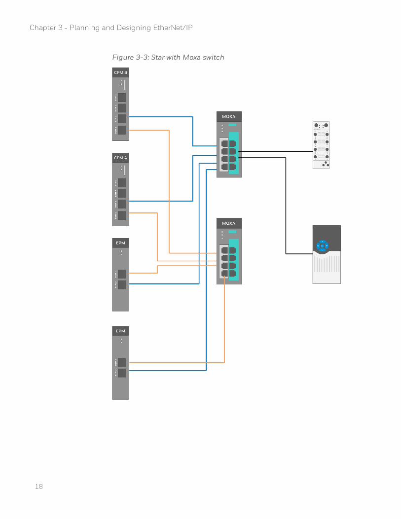
Figure 3-3: Star with Moxa switch
18
Chapter 3 - Planning and Designing EtherNet/IP

19
Figure 3-4: Star with Stratix 5700
Chapter 3 - Planning and Designing EtherNet/IP

Linear (Broken Ring) on Non-redundant CPM
n This topology applies to small projects and simple connection.
n It supports single port EtherNet/IP devices by ETAP and dual portdevices.
n If EPM is connected in the topology directly, CPM downlinknetwork topology must be configured as "Start Topology" (andRotary switch on EPM is setting as 5).For more information about how to configure the networktopology, see "Configuring ETH3 and ETH4 for ControlEdge 900Controller" in the ControlEdge Builder User's Guide.For more information about the rotary switch, see "Assembling I/Oracks" in the ControlEdge 900 Controller Hardware Planning andInstallation Guide.
n If EPM is connected in the topology through ETAP, CPM downlinknetwork topology must be configured as "Start Topology" (andRotary switch on EPM is set as 4).
Figure 3-5: Non-redundant CPM as Client through Linear
20
Chapter 3 - Planning and Designing EtherNet/IP

21
Common network for multiple CPM
n All EtherNet/IP devices connected with different CPMs can beconnected under the same network.
n Each device (EPM or EtherNet/IP device) only can be owned by aunique host (CPM). Not support to be owned by multiplecontrollers (except redundant controller).
n You must avoid IP conflict on each device.
n Common network topologies support both Device Level Ring andSTAR.
Figure 3-6: Downlink as Client through MOXA dual STAR
Chapter 3 - Planning and Designing EtherNet/IP

Figure 3-7: Downlink as Client through STRATIX for Device Level Ring
Network usage guidelines andrecommendations
Consider the guidelines and recommendations in the following table.
Guideline/Recommendation Explanation
Do not configure a supervisor (ETAP orstratix switch) on a linear network.
If your linear network includes non-DLRnodes and has a supervisor-enabled nodeon the network, it will impactcommunication to non-DLR devicesconnected to the linear network.
Connect switches to a DLR network via1783-ETAP.
If switches are connected to the DLRnetwork without a 1783-ETAP, thenetwork will experience unpredictablebehavior.
Run all nodes on the DLR network at 100Mbps and in Full-duplex mode.
These configuration values provide thebest performance for your network.
22
Chapter 3 - Planning and Designing EtherNet/IP

23
Guideline/Recommendation Explanation
Additionally, we recommend the following:
l Use auto-negotiate for all nodes on theDLR network.
l Do not use auto-negotiate on onenode and then force speed on the nextnode linked to it.
Do not physically close a DLR networkwithout a supervisor configured on thenetwork.
A DLR network without a supervisor noderesults in a network storm.
If you do close the DLR network without asupervisor configured, break the ring andconfigure at least one supervisor beforephysically reconnecting the network.
Chapter 3 - Planning and Designing EtherNet/IP

24
Chapter 3 - Planning and Designing EtherNet/IP

CHAPTER
4 CONFIGURATION
The following table lists workflows for different scenarios.
Task Go to
Configure EtherNet/IP Client Configure EtherNet/IP devices with EDS file:
1. See "Binding EtherNet/IP Client to anEthernet port" on page 27 for moreinformation.
2. See "Registering device types" on page 28for more information.
3. See "Configuring EtherNet/IP devicesusing EDS files" on page 36 for moreinformation.
If you do not have the EDS file, you canconfigure generic EtherNet/IP devices:
1. See "Binding EtherNet/IP Client to anEthernet port" on page 27 for moreinformation.
2. See "Configuring generic EtherNet/IPdevices" on page 44 for more information.
Configure EtherNet/IP Server 1. See "Binding EtherNet/IP Server to anEthernet port" on page 55 for moreinformation.
2. See "Selecting EtherNet/IP for variables"on page 55 for more information.
Configure communication withC300/UOC
When ControlEdge 900 controllercommunicates with C300/UOC, it acts as anEtherNet/IP Server. Only User-defined datatype STRUCT is supported for communicatingwith C300/UOC.
1. See "Binding EtherNet/IP Server to anEthernet port" on page 55 for moreinformation.
25
Task Go to
2. Declare a STRUCT data type. See"Configuring communication withC300/UOC" on page 53 for moreinformation.
3. Configure the target variable data type asthe STRUCT data type.
4. See "Selecting EtherNet/IP for variables"on page 55 for more information.
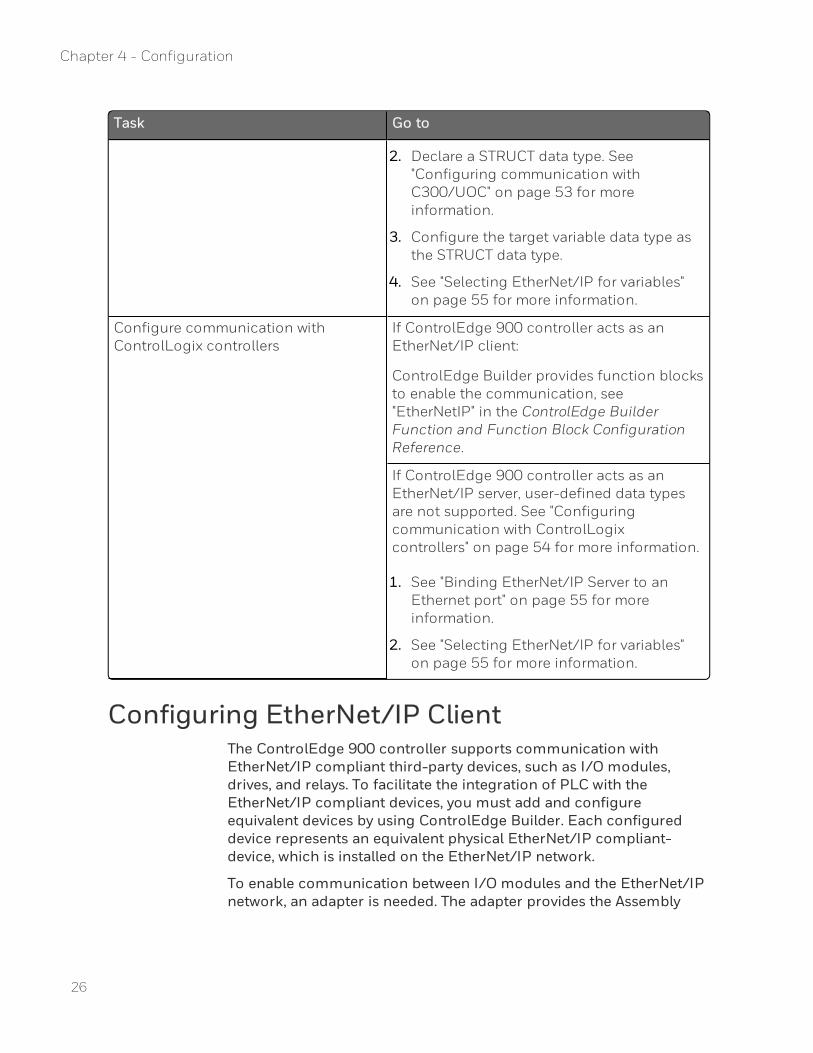
Configure communication withControlLogix controllers
If ControlEdge 900 controller acts as anEtherNet/IP client:
ControlEdge Builder provides function blocksto enable the communication, see"EtherNetIP" in the ControlEdge BuilderFunction and Function Block ConfigurationReference.
If ControlEdge 900 controller acts as anEtherNet/IP server, user-defined data typesare not supported. See "Configuringcommunication with ControlLogixcontrollers" on page 54 for more information.
1. See "Binding EtherNet/IP Server to anEthernet port" on page 55 for moreinformation.
2. See "Selecting EtherNet/IP for variables"on page 55 for more information.
Configuring EtherNet/IP ClientThe ControlEdge 900 controller supports communication withEtherNet/IP compliant third-party devices, such as I/O modules,drives, and relays. To facilitate the integration of PLC with theEtherNet/IP compliant devices, you must add and configureequivalent devices by using ControlEdge Builder. Each configureddevice represents an equivalent physical EtherNet/IP compliant-device, which is installed on the EtherNet/IP network.
To enable communication between I/O modules and the EtherNet/IPnetwork, an adapter is needed. The adapter provides the Assembly
26
Chapter 4 - Configuration

27
connection feature, which helps you in consolidating connectionsfrom a group of I/O modules.
You can create EtherNet/IP device, drive, and I/O module types byusing Electronic Data Sheets (EDS) files. Or if you do not have theEDS file, you can create a generic EtherNet/IP device.
Binding EtherNet/IP Client to an Ethernet portThis section introduces how to bind EtherNet/IP Client protocol toETH3.
ETH4 has the same configuration as ETH3, so only ETH3 should beconfigured manually.
Star or DLR topology is required if you bind EtherNet/IP Client.
To bind EtherNet/IP Client
1. From Home Page, click Configure Ethernet Ports and select ETH3.
2. Under Network Setting, configure the IP address and the subnetmask.
l The default IP address is 172.168.0.101.
l The range of the IP address is from 101 to 254.
l The IP address cannot be in the same network subnet as ETH1and ETH2.
l The IP address must be in the same network subnet as theEtherNet/IP device.
l The IP address cannot be conflict with the IP address ofEtherNet/IP device.
l The IP address cannot be conflict with the EPM IP address.
3. Under Protocol Binding, select EtherNet/IP Client.
4. Under I/O Network Topology, Select DLR Topology or Star Topology.This configuration should match the position of 100X switch onthe EPM hardware. 4 is for Star network topology and 5 is for DLRnetwork topology. For more information about the switch, see“Assembling I/O racks” in the ControlEdge 900 ControllerHardware Planning and Installation Guide.If you select DLR Topology, you should configure the following 4options.
Chapter 4 - Configuration
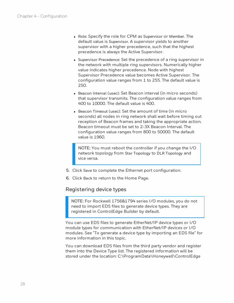
l Role: Specify the role for CPM as Supervisor or Member. Thedefault value is Supervisor. A supervisor yields to anothersupervisor with a higher precedence, such that the highestprecedence is always the Active Supervisor.
l Supervisor Precedence: Set the precedence of a ring supervisor inthe network with multiple ring supervisors. Numerically highervalue indicates higher precedence. Node with highestSupervisor Precedence value becomes Active Supervisor. Theconfiguration value ranges from 1 to 255. The default value is250.
l Beacon Interval (usec): Set Beacon interval (in micro seconds)that supervisor transmits. The configuration value ranges from400 to 10000. The default value is 400.
l Beacon Timeout (usec): Set the amount of time (in microseconds) all nodes in ring network shall wait before timing outreception of Beacon frames and taking the appropriate action.Beacon timeout must be set to 2-3X Beacon Interval. Theconfiguration value ranges from 800 to 50000. The defaultvalue is 1960.
NOTE: You must reboot the controller if you change the I/Onetwork topology from Star Topology to DLR Topology andvice versa.
5. Click Save to complete the Ethernet port configuration.
6. Click Back to return to the Home Page.
Registering device types
NOTE: For Rockwell 1756&1794 series I/O modules, you do notneed to import EDS files to generate device types. They areregistered in ControlEdge Builder by default.
You can use EDS files to generate EtherNet/IP device types or I/Omodule types for communication with EtherNet/IP devices or I/Omodules. See "To generate a device type by importing an EDS file" formore information in this topic.
You can download EDS files from the third party vendor and registerthem into the Device Type list. The registered information will bestored under the location: C:\ProgramData\Honeywell\ControlEdge
28
Chapter 4 - Configuration

29
Builder\EDSFiles. The registered information cannot be saved alongwith project backups. You must back up them manually.
If you want to modify EDS files, you can access EZ EDS tool fromODVA official website: https://www.odva.org/software/EZ-EDS-Download. For how to modify EDS file, check the online helpembedded in the EZ EDS tool.
You can also create a device type without an EDS file. See "To create adevice type without an EDS file" for more information in this topic.
Prerequisites
n If you want to create the EtherNet/IP device types, or I/O moduletypes by using the EDS, ensure that you have the appropriate EDSfile.
n Ensure that you have all the required device-related specifications,which are available with the device, before you create the device,or I/O module type.
To register device types
1. From the Home Page, click Configure EtherNet/IP Devices > RegisterDevice Types, and click Register Device Type. The following dialogappears:
2. Enter a Device Type Name. The device type name cannot begin withnumbers and cannot contain any spaces and special characters.
3. Select Device Type according to the type of the physicalEtherNet/IP device.If a device supports both Input and Output channels, then selectOutput here. For example, a device has analog input and analogoutput, then select Analog Output.If a device supports neither Input nor Output channels, then selectGeneric Device here.
4. When you register a device type for an I/O module, indicatewhether the I/O module requires an associated adapter or not. Ifthe I/O module requires an adapter, select the Needs Adapter box.
Chapter 4 - Configuration

NOTE: In a scenario where multiple I/O modules share asingle communication adapter to communicate with anEtherNet/IP protocol, the Needs Adapter must be selected.When you select Needs Adapter, the device type is onlyavailable on the I/O Configuration tab when you create orcustomize a generic EtherNet/IP Adapter.
NOTE: You cannot change this setting after compiling theproject. You must remove the device type from bothControlEdge Configuration Workspace and IECProgramming Workspace, and re-add a device type.
5. You can import an EDS file to generate a device type or create onewithout EDS files:
l To generate a device type by importing an EDS file
a. Click Select File, browse to the location stored the target EDSfile, select the EDS file and click Open.
b. You can view the basic information of the EDS file at thebottom panel. You can also click View EDS to open the EDSfile to view more details.
NOTE: The EDS file is read-only and not allowed to bemodified here.
c. Select the boxes for the following Assembly types accordingto devices types:
30
Chapter 4 - Configuration

31
l InputAn assembly transfers data from an EtherNet/IP device asProducer device to a controller as Consumer.
l OutputAn assembly transfers data from a controller as Producerdevice to an EtherNet/IP device as Consumer.
l ConfigurationAn assembly which transports configuration data fromthe EtherNet/IP device originating the connection to theEtherNet/IP device or IO module which is the target ofthe connection.
NOTE: There might be more than one Input, Outputand Configuration assembly types. However, ensurethat you select one instance of Input, one instance ofOutput, and one instance of Configuration assemblytype per your requirement.
d. Click OK to register the device type to ControlEdge Builder.Device types are created and grouped by different vendorsautomatically based on the "vendor" information in the EDSfile.
Chapter 4 - Configuration

l To create a device type without an EDS file
a. Click Next, and the following dialog appears:
b. Select the boxes for the following Assembly types accordingto devices types:
l InputAn assembly transfers data from an EtherNet/IP device asProducer device to a controller as Consumer.
l OutputAn assembly transfers data from a controller as Producerdevice to an EtherNet/IP device as Consumer.
l ConfigurationAn assembly which transfers configuration data from theEtherNet/IP device originating the connection to theEtherNet/IP device or IO module which is the target ofthe connection.
32
Chapter 4 - Configuration

33
NOTE: You must select at least one instance ofInput/Output/Configuration assembly per yourrequirement.
c. Enter Assembly Name, Instance Number and Size (In Bytes) forthe selected Assembly.
ATTENTION: Instance Number must be greater than 0.
ATTENTION: At least one Size (In Bytes) must begreater than 0.
d. Select Vendor Name from the drop-down list and otherinformation is displayed automatically.
e. Click OK to register the device type to ControlEdge Builder.
6. Click the vendor name to expand the group, and select the targetdevice type, you can view General, Configuration Assembly, InputAssembly and Output Assembly information.
7. You can click the Delete icon to remove the device type.
8. You can click the Edit Device Type icon to modify the device type.See "Editing device types" on the next page for more information.
9. Click Save to complete the configuration.After saving, the new device type will be populated in the Data Typelibrary with an input and output channel in IEC ProgrammingWorkspace. You can use the created device type from the library toconfigure new devices.
Chapter 4 - Configuration

Editing device typesThis feature enables you to edit device types using ControlEdgeBuilder.
To edit a device type
1. From the Home Page, click Configure EtherNet/IP Devices > RegisterDevice Types.
2. Select the device type you want to modify and click the Edit DeviceType icon. The Edit Device Type dialog appears.
3. In the Configuration Assembly, Input Assembly and Output Assemblytab, you can configure the following parameters per yourrequirements. For more information, see the vendor's document.
Parameter Description
Enable Run/IdleHeader
It is only applicable for Input Assemblyand Output Assembly.
Parameter Name Parameter name
Parameter Description Parameter description
Data Type Data type of the parameter. The followingoptions are available:
34
Chapter 4 - Configuration

35
Parameter Description
l BOOL
l INT8
l BYTE
l UINT8
l UINT16
l INT16
l UINT32
l INT32
l UINT64
l INT64
l FLOAT32
l REAL
l LREAL
l FLOAT64
Is Enumerated Select to enable Enumerate
Enumerate It is configurable if Is Enumerated isselected.
Click Enumerate to configure values:
1. Enter Value and String, and clickInsert.
2. Click OK.
Offset The initial bit for the parameter
Size (in bits) Parameter size
Default Value Select the configuration of Enumerate
If Enumerate is not configured, enter thevalue per your requirement.
Minimum Value Minimum value of the parameter
It depends on the data type.
Chapter 4 - Configuration

Parameter Description
Maximum Value Maximum value of the parameter
It depends on the data type.
4. (Optional) You can click to add a new parameter.
NOTE: Size (Bits) of existing parameters cannot exceed theTotal Size (Bytes).
5. (Optional) You can click to delete all parameters.
6. (Optional) You can click to delete a parameter.
7. Click OK to complete the configuration.
Configuring EtherNet/IP devices using EDS filesPrerequisites
n Ensure you have registered the device type by using the EDS file ofthe EtherNet/IP device into ControlEdge Builder. See "Registeringdevice types" on page 28 for more information.
n The following information in the EDS file are critical for devicetype creation. Ensure that these details are available before usingthe EDS file.
l Device and Vendor information
l Parameter information
l Assembly information
l Connection information
n Bind EtherNet/IP Client to an Ethernet port. See "BindingEtherNet/IP Client to an Ethernet port" on page 27 for moreinformation.
To configure a device using an EDS file, without an adapter
1. From the Home Page, click Configure EtherNet/IP Devices >Configure Devices, and click Add Device.
2. Click Select Device Type, and all available device types are displayed.
36
Chapter 4 - Configuration

37
You can enter keywords to search device types, and also can filterthem by selecting from the various filters for the Vendor andCategory fields.
3. Select the target device type, and enter the Device Name andDescription. The device name cannot begin with numbers andcannot contain any spaces and special characters.
4. Click OK to add the device.
5. In the General tab, configure the following parameters.
Parameter Description
IP Address The IP address of the EtherNet/IPdevice which is provided by thevendor.
Electronic Keying It is used to control if accept theconnection when the identityinformation of EDS file does notmatch the EtherNet/IP device.
l Disable Keying: Allow theconnection with EtherNet/IPdevice even the identityinformation of EDS file and theEtherNet/IP device do notmatch.
Chapter 4 - Configuration

Parameter Description
l Exact Match: The identityinformation of EDS file mustmatch the EtherNet/IP device,and then the connection will beallowed.
Connection TimeoutMultiplier
Configure it according to Vendor'sdocument.
The following options are available: *4,*8, *16, *32, *64, *128, *256, *512 andComputed.
Originator to Target RPI(ms)
Requested Packet Interval (RPI)specifies the rate at which data isupdated during a connection.
Set the rate for initiating the dateexchange with the EtherNet/IP device.
Connection Type The following options are available:
l Null
l Multicast
l Point2Point
It is recommended to use the defaultvalue.
Priority The following options are available:
l Low
l High
l Scheduled
l Urgent
It is recommended to use the defaultvalue.
Target to Originator RPI(ms)
Set the rate for reading data from theEtherNet/IP device.
Connection Type The following options are available:
38
Chapter 4 - Configuration

39
Parameter Description
l Null
l Multicast
l Point2Point
ATTENTION: For outputmodules, select Multicast.
ATTENTION: For other types ofmodules, use the default value.
Priority The following options are available:
l Low
l High
l Scheduled
l Urgent
It is recommended to use the defaultvalue.
6. Click Configuration tab to configure parameters which are definedby the corresponding EDS file. Configure them according tovendor's documents.
7. In the Configuration tab, you can also do the following options ifrequired:
l Click Change Device Type to re-select a device type.
l Click Clear Device Type to remove the device type.
8. You can click to edit the device name and description. You can
also click to remove the device if required.
9. Click Save to complete the configuration.
To configure a device using an EDS file, associated with an adapter
1. From the Home Page, click Configure EtherNet/IP Devices >Configure Devices, and click Add Device.
2. Select Create or Customize EtherNet/IP Device, and select Generic
Chapter 4 - Configuration

EtherNet/IP Adapter.
3. Enter the Number of Slots ranging from 1 to 64.
ATTENTION: An attempt to communicate with the I/Omodule fails if the number of slots entered does not matchthe physical configuration. Therefore, ensure that thenumber of slots matches the number of the physicallyinstalled I/O modules and the adapter (number of slots =number of I/O modules + one for the adapter). For example,if the number of I/O modules is 7, the number of slotsshould be 8.
4. Enter the Device Name and Description. The device name cannotbegin with numbers and cannot contain any spaces and specialcharacters.
5. Click OK to add the device.
6. In the General tab, configure the following parameters.
Parameter Description
IP Address The IP address of theEtherNet/IP device.
Apply RPI settings on all associatedI/O modules
Select the checkbox toapply the specified RPI toall I/O modules associatedto the adapter.
40
Chapter 4 - Configuration
41
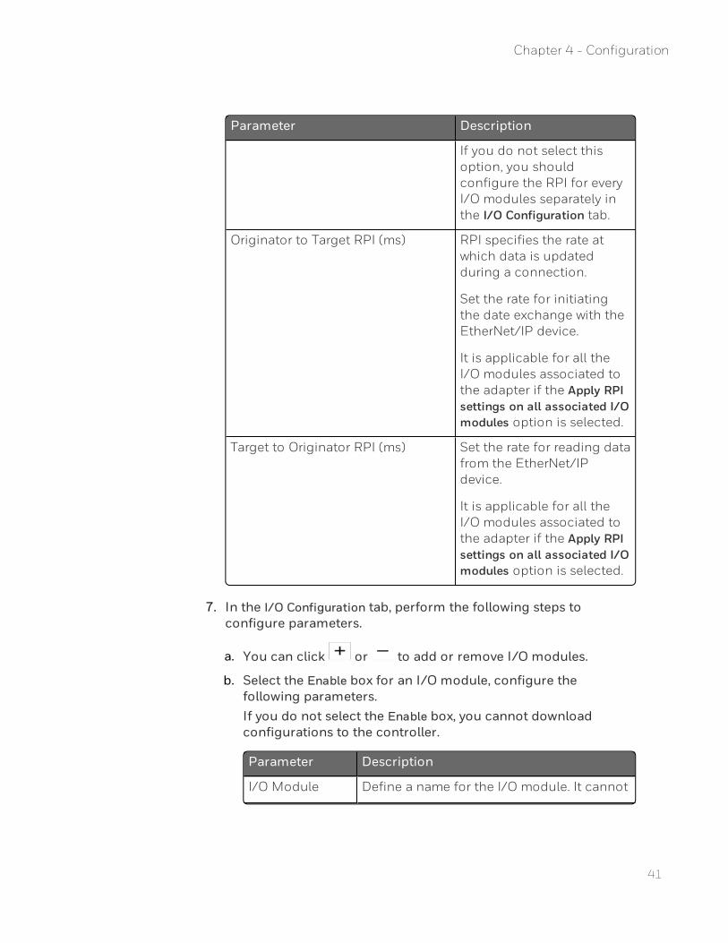
Parameter Description
If you do not select thisoption, you shouldconfigure the RPI for everyI/O modules separately inthe I/O Configuration tab.
Originator to Target RPI (ms) RPI specifies the rate atwhich data is updatedduring a connection.
Set the rate for initiatingthe date exchange with theEtherNet/IP device.
It is applicable for all theI/O modules associated tothe adapter if the Apply RPIsettings on all associated I/Omodules option is selected.
Target to Originator RPI (ms) Set the rate for reading datafrom the EtherNet/IPdevice.
It is applicable for all theI/O modules associated tothe adapter if the Apply RPIsettings on all associated I/Omodules option is selected.
7. In the I/O Configuration tab, perform the following steps toconfigure parameters.
a. You can click or to add or remove I/O modules.
b. Select the Enable box for an I/O module, configure thefollowing parameters.If you do not select the Enable box, you cannot downloadconfigurations to the controller.
Parameter Description
I/O Module Define a name for the I/O module. It cannot
Chapter 4 - Configuration

Parameter Description
Name begin with numbers and cannot contain anyspaces and special characters.
ConnectionTimeoutMultiplier
Configure it according to Vendor'sdocument.
The following options are available: *4, *8,*16, *32, *64, *128, *256, *512 and Computed.
ATTENTION: For Rockwell1756&1794 series I/O modules, thevalue of multiplying this parameter byRPI cannot exceed 1600. Forexample, if RPI is set as 50,Connection Timeout Multipliercannot be set larger than 32.
Originator toTarget RPI (ms)
Set the rate for initiating the date exchangewith the EtherNet/IP device.
It is un-configurable if the Apply RPI settingson all associated I/O modules option isselected in the General tab.
Connection Type The following options are available:
l Null
l Multicast
l Point2Point
It is recommended to use the default value.
Priority The following options are available:
l Low
l High
l Scheduled
l Urgent
It is recommended to use the default value.
Target toOriginator RPI
Set the rate for reading data from theEtherNet/IP device.
42
Chapter 4 - Configuration

43
Parameter Description
(ms) It is un-configurable if the Apply RPI settingson all associated I/O modules option isselected in the General tab.
Connection Type The following options are available:
l Null
l Multicast
l Point2Point
ATTENTION: For output modules,select Multicast.
ATTENTION: For other types ofmodules, use the default value.
Priority The following options are available:
l Low
l High
l Scheduled
l Urgent
It is recommended to use the default value.
c. Click Select Device Type to choose a device type. The SelectDevice Type dialog appears.The available device types are displayed. You can enterkeywords to search device types, and also can filter them byselecting from the various filters for the Vendor and Categoryfields.
d. Select the target device type, and click Next to configure moreparameters which are defined in the corresponding EDS file.Configure them according to vendor's documents.For some Input and Output parameters of Rockwell1756&1794 series I/O modules, See "Input and Outputparameter of Rockwell 1756 and 1794 series I/O modules" onpage 49 for more information.
Chapter 4 - Configuration

e. Click OK to add the device type.
f. You can select Edit Device Type to re-configure the device type.The Edit Configuration Assembly dialog appears.
l Click Change Device Type to re-select a device type.
l Click Clear Device Type to remove the device type.
g. If you complete all the configurations, the Status will change
from to .
8. From the left panel, you can click to edit the device name and
description. You can also click to remove the device if required.
9. Click Save to complete the configuration.
Configuring generic EtherNet/IP devicesIf you do not have the EDS file, you can create and configure ageneric EtherNet/IP device.
Prerequisites
n Ensure that the following details are available before creating andconfiguring the device:
l Device and Vendor information
l Parameter information
l Assembly information
l Connection information
n Bind EtherNet/IP Client to an Ethernet port. See "BindingEtherNet/IP Client to an Ethernet port" on page 27 for moreinformation.
To configure a generic EtherNet/IP device
1. From the Home Page, click Configure EtherNet/IP Devices >Configure Devices, and click Add Device.
2. Select Create or Customize EtherNet/IP Device, and select GenericEtherNet/IP Device.
44
Chapter 4 - Configuration

45
3. Enter the Device Name and Description. The device name cannotbegin with numbers and cannot contain any spaces and specialcharacters.
4. Click OK to add the device.
5. In the General tab, configure the following parameters.
Parameter Description
IP Address The IP address of theEtherNet/IP device
Connection Timeout Multiplier Configure it according toVendor's document.
The following options areavailable: *4, *8, *16, *32,*64, *128, *256, *512 andComputed.
Originator to Target RPI (ms) Set the rate for initiatingthe date exchange with theEtherNet/IP device.
Connection Type The following options areavailable:
l Null
l Multicast
l Point2Point
Chapter 4 - Configuration

Parameter Description
It is recommended to usethe default value.
Priority The following options areavailable:
l Low
l High
l Scheduled
l Urgent
It is recommended to usethe default value.
Target to Originator RPI (ms) Set the rate for readingdata from the EtherNet/IPdevice.
Connection Type The following options areavailable:
l Null
l Multicast
l Point2Point
ATTENTION: Foroutput modules,select Multicast.
ATTENTION: Forother types ofmodules, use thedefault value.
Priority The following options areavailable:
l Low
l High
l Scheduled
46
Chapter 4 - Configuration

47
Parameter Description
l Urgent
It is recommended to usethe default value.
6. In the Connection tab, configure the following parameters.
Parameter Description
CommunicationFormat
The data type of the update data readingfrom EtherNet/IP devices.
There are four options: DINT, INT, REAL,and SINT
Input Input assembly: An assembly transfers datafrom an EtherNet/IP device as Producerdevice to a controller as Consumer.
Output Output assembly: An assembly transfersdata from a controller as Producer deviceto an EtherNet/IP device as Consumer.
Configuration Configuration assembly: An assembly whichtransports configuration data from theEtherNet/IP device originating theconnection to the EtherNet/IP device or IOmodule which is the target of theconnection.
Assembly Instance The assembly instance number provided bythe vendor. For more information, see thevendor's specification.
Size The data length of the assembly providedby the vendor. For more information, seethe vendor's specification.
7. You can click to edit the device name and description. You can
also click to remove the device if required.
8. Click Save to complete the configuration.
Chapter 4 - Configuration

Scaling support for generic deviceScaling support covers custom parameters as well as PV and OPparameters on generic devices.
Formulae used by the controller to perform scaling:
1. FLOATVALUE for Custom Input parameters is calculated as:
2. For the Output direction, use this formula to calculate RAWVALUEfrom the FLOATVALUE (which is typically written through thestrategy):
The formula is the same as with Input scaling solved for 'Raw value'.
The process value that is received from field is converted to digitalform by the A/D converter. LOWRANGE and HIGHRANGE valuesdefine the normal operating range of the RAW value.
RAW value in the output direction is the final output value sent to thedevice in the output assembly. This is the linearly scaled value (withsome scale factor multiplied and bias added) of the OP (which is inpercentage) within the LOWRANGE and HIGHRANGE operating rangeof the RAW value.
48
Chapter 4 - Configuration

49
Input and Output parameter of Rockwell 1756 and1794 series I/O modulesThis topic introduces some parameter configuration for EDS files ofRockwell 1756&1794 series I/O modules.
Table 4-1: 1756-OF4 Analog Output Current/Voltage 4 Channel
Device type Parameter Data type Description Example
Float ChannelStatus0
USINT/8 B6 is not used.
l B0(bit):Ch0HLimitAlarm
l B1(bit):Ch0LLimitAlarm
l B2(bit):Ch0RampAlarm
l B3(bit):Ch0InHold
l B4(bit):Ch0CalFault
l B5(bit):Ch0NotANumber
l B7(bit):Ch0OpenWire
Integer
ChannelFaults0
UINT/16/Byte0
l B0(bit):Ch0Fault
l B1(bit):Ch1Fault
l B2(bit):Ch2Fault
l B3(bit):Ch3Fault
Chapter 4 - Configuration

Device type Parameter Data type Description Example
ChannelStatus0
UINT/16/Byte1
l B0(bit):Ch3InHold
l B1(bit):Ch3OpenWire
l B2(bit):Ch2InHold
l B3(bit):Ch2OpenWire
l B4(bit):Ch1InHold
l B5(bit):Ch1OpenWire
l B6 (bit):Ch0InHold
l B7(bit):Ch0OpenWire
ModuleFaults0
UINT/16/Byte1
l B5(bit):CalFault
l B6(bit):Calibrating
l B7(bit):AnalogGroupFault
Table 4-2: 1794-IE8/B 8 channel 24 DC Non-isolated Voltage/Current Analog Input
Parameter Data type Description Example
Config_0 UINT/16l B0(bit):Ch0FullRange
l B1(bit):Ch1FullRange
l B2(bit):Ch2FullRange
None
50
Chapter 4 - Configuration

51
Parameter Data type Description Example
l B3(bit):Ch3FullRange
l B4(bit):Ch4FullRange
l B5(bit):Ch5FullRange
l B6(bit):Ch6FullRange
l B7(bit):Ch7FullRange
l B8(bit):Ch0ConfigSelect
l B9(bit):Ch1ConfigSelect
l B10(bit):Ch2ConfigSelect
l B11(bit):Ch3ConfigSelect
l B12(bit):Ch4ConfigSelect
l B13(bit):Ch5ConfigSelect
l B14(bit):Ch6ConfigSelect
l B15(bit):Ch7ConfigSelect
Chapter 4 - Configuration

Parameter Data type Description Example
Status0 UINT/16/Byte0
l B0(bit):Ch0Underrange
l B1(bit):Ch1Underrange
l B2(bit):Ch2Underrange
l B3(bit):Ch3Underrange
l B4(bit):Ch4Underrange
l B5(bit):Ch5Underrange
l B6(bit):Ch6Underrange
l B7(bit):Ch7Underrange
Table 4-3: 1794-OE8H/A 8 Channel Analog Output/HART
Parameter Data type Description Example
DigitalData0 USINTl B0(bit):DigitalData0
l B1(bit):DigitalData1
l B2(bit):DigitalData2
l B3(bit):DigitalData3
l B4(bit):DigitalData4
l B5(bit):DigitalData5
l B6(bit):DigitalData6
52
Chapter 4 - Configuration

53
Parameter Data type Description Example
l B7(bit):DigitalData7
Configuring communication with third-partycontrollers
Configuring communication with C300/UOCWhen ControlEdge 900 controller communicates with C300/UOC, itacts as an EtherNet/IP Server. Only User-defined data type STRUCT issupported for communicating with C300/UOC, which can include thefollowing elementary data types:
n DATATYPE_BOOL (0x01)
n DATATYPE_SINT (0x02)
n DATATYPE_INT (0x03)
n DATATYPE_DINT (0x04)
n DATATYPE_USINT (0x05)
n DATATYPE_UINT (0x06)
n DATATYPE_UDINT (0x07)
n DATATYPE_REAL (0x08)
1. Bind EtherNet/IP Server to an Ethernet port. See "BindingEtherNet/IP Server to an Ethernet port" on page 55 for moreinformation.
2. Declare a STRUCT data type.
a. From IEC Programming Workspace, right-click Data Types, selectInsert > Datatypes.
b. Enter a name for the data type, and click OK.
c. Double click the new data type, and from Edit Wizard, doubleclick STRUCT.
d. Enter the target elementary data types, and click Save.
Chapter 4 - Configuration
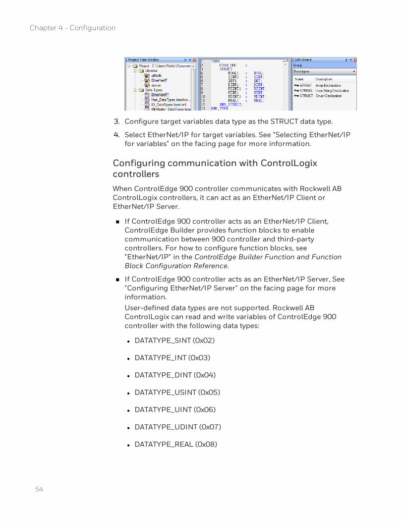
3. Configure target variables data type as the STRUCT data type.
4. Select EtherNet/IP for target variables. See "Selecting EtherNet/IPfor variables" on the facing page for more information.
Configuring communication with ControlLogixcontrollersWhen ControlEdge 900 controller communicates with Rockwell ABControlLogix controllers, it can act as an EtherNet/IP Client orEtherNet/IP Server.
n If ControlEdge 900 controller acts as an EtherNet/IP Client,ControlEdge Builder provides function blocks to enablecommunication between 900 controller and third-partycontrollers. For how to configure function blocks, see"EtherNet/IP" in the ControlEdge Builder Function and FunctionBlock Configuration Reference.
n If ControlEdge 900 controller acts as an EtherNet/IP Server, See"Configuring EtherNet/IP Server" on the facing page for moreinformation.User-defined data types are not supported. Rockwell ABControlLogix can read and write variables of ControlEdge 900controller with the following data types:
l DATATYPE_SINT (0x02)
l DATATYPE_INT (0x03)
l DATATYPE_DINT (0x04)
l DATATYPE_USINT (0x05)
l DATATYPE_UINT (0x06)
l DATATYPE_UDINT (0x07)
l DATATYPE_REAL (0x08)
54
Chapter 4 - Configuration

55
Configuring EtherNet/IP ServerThis section introduces how to configure ControlEdge 900 controlleras an EtherNet/IP Server. EtherNet/IP Client can read, write andmonitor global variable, program local variable of the EtherNet/IPServer through the Tag name configured in EtherNet/IP Client.
Global variable's tag name is@GV. <Varname>. If some controllers donot support special characters such as @, the tag name should beGV.GV.<Varname>.
Program Local variable's tag name is <Program InstanceName>.<Varname>.
Binding EtherNet/IP Server to an Ethernet portThis section introduces how to bind EtherNet/IP Server to ETH1 orETH2. Only one Ethernet port can be bound at a time.
To bind EtherNet/IP Server
1. From Home Page, click Configure Ethernet Ports and select ETH1 orETH2.
2. Under Network Setting, configure the IP addresses, subnet maskand gateway.
3. Under Protocol Binding, select EtherNet/IP Server.
4. Click Save to complete the Ethernet port configuration.
5. Click Back to return to the Home Page.
Selecting EtherNet/IP for variablesEtherNet/IP must be selected for global variables or program localvariables of EtherNet/IP Server, so that EtherNet/IP Client can read,write and monitor these variables through the Tag name configuredin EtherNet/IP Client.
Global variable's tag name is@GV. <Varname>. If some controllers donot support special characters such as @, the tag name should beGV.GV.<Varname>.
Program Local variable's tag name is <Program InstanceName>.<Varname>.
1. Click IEC Programming Workspace on the toolbar, or from HomePage, click Program with IEC61131-3.
2. Perform either of the following methods to select EIP for local
Chapter 4 - Configuration

variables or global variables.
l From the variable sheets, select EIP.
l From the variable properties dialog, select EIP.
3. Compile the configuration to the controller. See "Compiling aproject" in ControlEdge Builder User's Guide.
56
Chapter 4 - Configuration

CHAPTER
5 ETHERNET/IP I/O BEHAVIOR DURINGSWITCHOVER
On controllers switchover there will be a control freeze for 200 ms toa maximum of 2 seconds.
The control freeze time is due to controllers reforming theEtherNet/IP I/O connections from the new primary and getting thelatest publication from the I/O.
NOTE: This time is dependent on the number of EtherNet/IP I/OModules configured.
During this time the IOM and channel blocks in the controllers willhold and work on with the last I/O data received before switchover.
57

58
Chapter 5 - EtherNet/IP I/O Behavior during switchover

CHAPTER
6 DIAGNOSTIC
Configuring DLR network statusYou can log in as the Administrator, Engineer or Operator to connectthe target controller and configure DLR network status.
1. From the Home Page, click View Diagnostics under Diagnostics. Thediagnostics page appears.
2. Auto-refresh is selected by default, you can set a refresh rate toupdate diagnostics regularly. You can also click Auto-refresh toclose it, and click Refresh to update diagnostics manually.
3. Click Platform, and select Locate fault or Recover from Rapid Fault toset the DLR network status.
Name Description
Locatefault
When Ring Fault occurs in the DLR Network Status,click this button and check the IP address in DLR LastActive Node Port 1 and DLR Last Active Node Port 2 toidentify the fault location.
RecoverfromRapidFault¹
When Rapid Fault occurs in the DLR Network Status,click this button to recover the networkcommunication if the fault is resolved.
Note1: Rapid fault may be caused by any of the following:
l Manually disconnect or reconnect network nodes 5 timesin 30 seconds
l Duplex mismatch between two connected devices
l Bad Electro Magnetic Compatibility (EMC) environment
l Unstable physical connections
Viewing EtherNet/IP device diagnosticsYou can log in as the Administrator, Engineer or Operator to connectthe target controller and view EtherNet/IP device diagnostics.
59
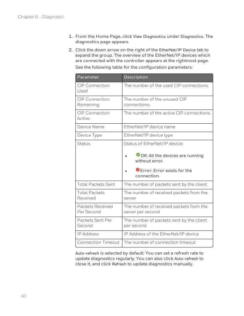
1. From the Home Page, click View Diagnostics under Diagnostics. Thediagnostics page appears.
2. Click the down arrow on the right of the EtherNet/IP Device tab toexpand the group. The overview of the EtherNet/IP devices whichare connected with the controller appears at the rightmost page.See the following table for the configuration parameters:
Parameter Description
CIP ConnectionUsed
The number of the used CIP connections.
CIP ConnectionRemaining
The number of the unused CIPconnections.
CIP ConnectionActive
The number of the active CIP connections.
Device Name EtherNet/IP device name
Device Type EtherNet/IP device type
Status Status of EtherNet/IP device:
l OK: All the devices are runningwithout error.
l Error: Error exists for theconnection.
Total Packets Sent The number of packets sent by the client
Total PacketsReceived
The number of received packets from theserver
Packets ReceivedPer Second
The number of received packets from theserver per second
Packets Sent PerSecond
The number of packets sent by the clientper second
IP Address IP Address of the EtherNet/IP device
Connection Timeout The number of connection timeout
Auto-refresh is selected by default. You can set a refresh rate toupdate diagnostics regularly. You can also click Auto-refresh toclose it, and click Refresh to update diagnostics manually.
60
Chapter 6 - Diagnostic

61
You can click Reset Statistics to reset statistic values to the defaultvalues.
3. Click an EtherNet/IP device name to view its diagnostics displayedat the rightmost page.
Parameter Description
Module Status The status of EtherNet/IP device
See "EtherNet/IP device error codes" on thenext page for more information.
IP Address The IP Address of EtherNet/IP device
Device Type The EtherNet/IP device type
Vendor Vendor of EtherNet/IP device
Product Code EtherNet/IP device code
Revision EtherNet/IP device revision
Total PacketsSent
The number of packets sent by the client
Total PacketsReceived
The number of received packets from theserver
Packets Sent PerSecond
The number of packets sent by the client persecond
Packets ReceivedPer Second
The number of received packets from theserver per second
CommunicationErrors
The number of communication error
CommunicationTimeout
The number of device offline
4. For the EtherNet/IP device with an adapter, click the down arrowat the right of the device to view I/O module list. Click an I/Omodule to view its diagnostics.
Parameter Description
Module Status The status of I/O module
Chapter 6 - Diagnostic

Parameter Description
IP Address The IP Address of I/O module
Device Type The I/O module type
Vendor Vendor of EtherNet/IP device
Product Code EtherNet/IP device code
Revision EtherNet/IP device revision
Total Packets Sent The number of packets sent by the client
Total PacketsReceived
The number of received packets from theserver
Packets Sent PerSecond
The number of packets sent by the clientper second
Packets ReceivedPer Second
The number of received packets from theserver per second
CommunicationErrors
The number of communication error
CommunicationTimeout
The number of device offline
EtherNet/IP device error codesEtherNet/IP device diagnostics are also displayed in IEC ProgrammingWorkspace. Click IEC Programming Workspace, double-click Global_Variables, and check the EtherNetIP Diagnostics group.
Error code Status Description
0x0000 EIP_IO_STATE_STANDBY Device is standby.
0x1000 EIP_IO_STATE_FAULTED Connecting failed
0x1100 EIP_IO_STATE_FAULTED_WAITING_TO_CONNECT
Connecting failed, waiting to re-connect
0x1200 EIP_IO_STATE_FAULTED_CONNECTING
Connecting failed, re-connecting
0x1300 EIP_IO_STATE_FAULTED_BAD_IP_ADDR
Invalid IP address specified
62
Chapter 6 - Diagnostic

63
Error code Status Description
0x1400 EIP_IO_STATE_FAULTED_SERVER_ALLOC_FAILED
I/O server allocation failed
0x1500 EIP_IO_STATE_FAULTED_IO_ALLOC_FAILED
I/O allocation failed
0x1600 EIP_IO_STATE_FAULTED_BAD_T2O_DATAPTR
Invalid Target to Originator data sizeand/or pointer
0x1700 EIP_IO_STATE_FAULTED_BAD_O2T_DATAPTR
Invalid Originator to Target data sizeand/or pointer
0x1800 EIP_IO_STATE_FAULTED_BAD_T2O_RPI
Invalid Target to Originator RPI
0x1900 EIP_IO_STATE_FAULTED_BAD_O2T_RPI
Invalid Originator to Target RPI
0x1a00 EIP_IO_STATE_FAULTED_BAD_CONFIGPTR
Invalid configuration size and/orpointer
0x3000 EIP_IO_STATE_CONNECTING Connecting
0x4000 EIP_IO_STATE_RUNNING Running
0x5000 EIP_IO_STATE_SHUTTING_DOWN
Shutting down
0x7100 EIP_IO_STATE_WAITING_TO_CONNECT
Waiting to connect
0x7200 EIP_IO_STATE_WAITING_TO_SHUTDOWN
Waiting to shut down
0x7300 EIP_IO_STATE_WAITING_TO_RECONNECT
Re-connect after forward close,instead of freeing I/O
0x9000 EIP_IO_STATE_CNTRLR_SWITCHOVER
Forward closing of I/O modules withinput channels after the controllerswitch over
Chapter 6 - Diagnostic

64
Chapter 6 - Diagnostic

APPENDIX
AThe error codes are returned with the response to a Connection Manager ServiceRequest that resulted in an error. These error codes shall be used to help diagnosethe problem with a Service Request. The error code shall be split into an 8 bitgeneral status and one or more 16- bit words of extended status. Unless specifiedotherwise, only the first word of extended status shall be required. Additional wordsof extended status may be used to specify additional device specific information. Alldevices that originate messages shall be able to handle multiple words of extendedstatus.
See "Connection Manager Object Instance Error codes" in the Common IndustrialProtocol Specification for definitions of status codes. If any questions, you cancontact Honeywell representatives.
STATUS CODES
65

Notices
NOTICES
Trademarks
Experion® is a registered trademark of Honeywell International, Inc.
ControlEdge™ is a trademark of Honeywell International, Inc.
Other trademarks
Microsoft and SQL Server are either registered trademarks or trademarks ofMicrosoft Corporation in the United States and/or other countries.
Trademarks that appear in this document are used only to the benefit of thetrademark owner, with no intention of trademark infringement.
Third-party licenses
This product may contain or be derived from materials, including software, ofthird parties. The third party materials may be subject to licenses, notices,restrictions and obligations imposed by the licensor. The licenses, notices,restrictions and obligations, if any, may be found in the materials accompanyingthe product, in the documents or files accompanying such third party materials, ina file named third_party_licenses on the media containing the product, or athttp://www.honeywell.com/ps/thirdpartylicenses.
Documentation feedback
You can find the most up-to-date documents on the Honeywell Process Solutionssupport website at: http://www.honeywellprocess.com/support
If you have comments about Honeywell Process Solutions documentation, sendyour feedback to: [email protected]
Use this email address to provide feedback, or to report errors and omissions inthe documentation. For immediate help with a technical problem, contact yourlocal Honeywell Technical Assistance Center (TAC).
How to report a security vulnerability
For the purpose of submission, a security vulnerability is defined as a softwaredefect or weakness that can be exploited to reduce the operational or securitycapabilities of the software.
66

Notices
Honeywell investigates all reports of security vulnerabilities affecting Honeywellproducts and services.
To report a potential security vulnerability against any Honeywell product, pleasefollow the instructions at:
https://honeywell.com/pages/vulnerabilityreporting.aspx
Support
For support, contact your local Honeywell Process Solutions Customer ContactCenter (CCC). To find your local CCC visit the website,https://www.honeywellprocess.com/en-US/contact-us/customer-support-contacts/Pages/default.aspx.
Training classes
Honeywell holds technical training classes that are taught by process controlsystems experts. For more information about these classes, contact yourHoneywell representative, or see http://www.automationcollege.com.
67

Notices
68


![a E]`YU`]c^ ^`]RcQbWdWbgbrochure.copiercatalog.com/lexmark/x548-series-brochure.pdf · :Sf[O`Y F#"& 4O[WZg 9Sg 4SObc`Sa 5 3 6 1 4 7 2 4SObc`Sa b] ]^bW[WhS g]c` e]`Y Lexmark X548de](https://static.documents.pub/doc/80x56/60368141d627f0265e300968/a-eyuc-sfoy-f-4owzg-9sg-4sobcsa-5-3-6-1-4-7-2-4sobcsa.jpg)


