Nicola Pullan asserts her moral right to be identified as the author of this thesis.
This copy of the thesis has been supplied on condition that anyone who consults it is understood to
recognise that its copyright rests with its author and that no quotation from the thesis and no
information derived from it may be published without appropriate permission or acknowledgement.
2
Aston University
Controlled Polymerisation and Industrial Application of
Poly(2-Chloro-1,3-Butadiene)
Nicola Pullan
Doctor of Philosophy
2014
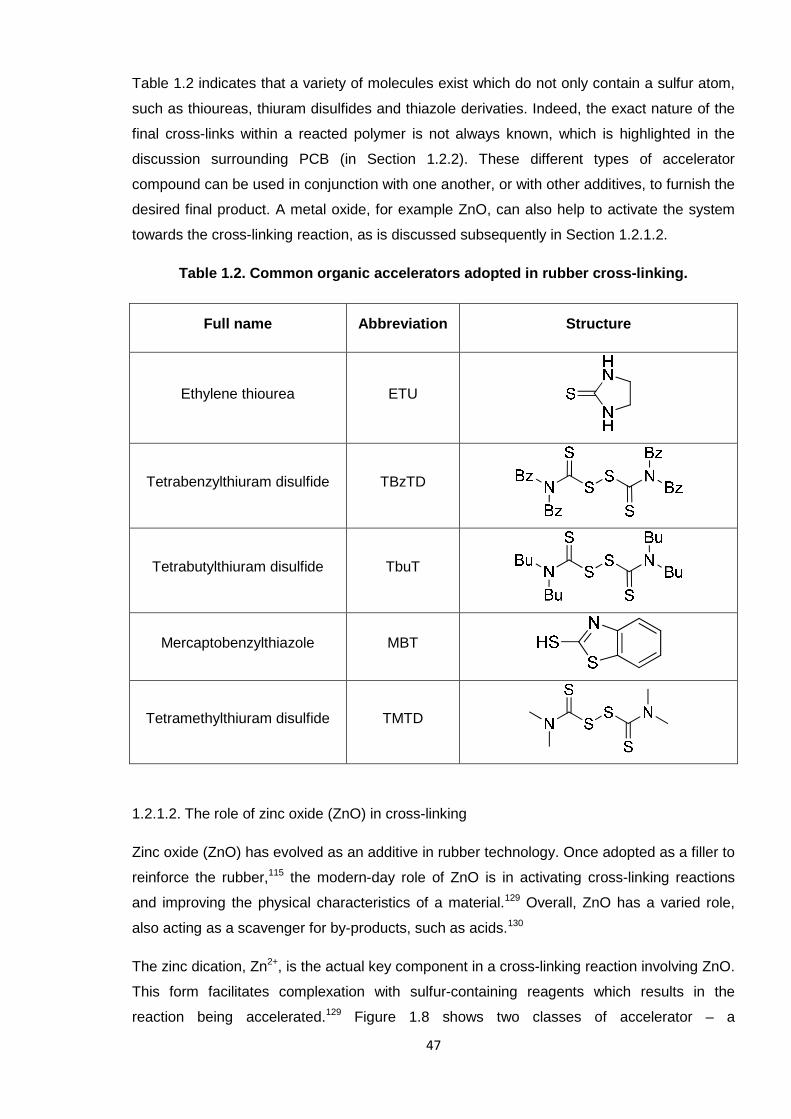
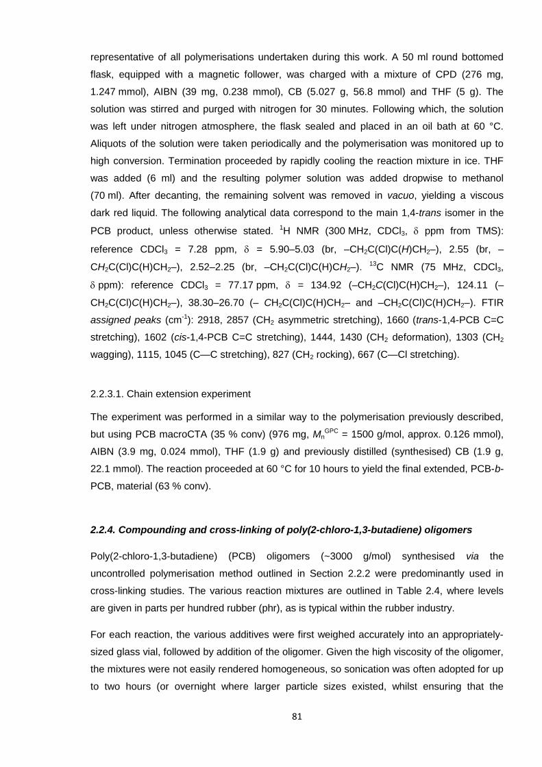
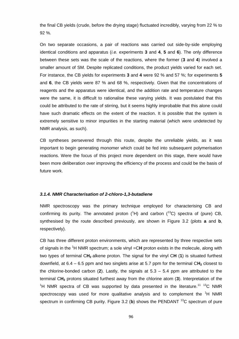
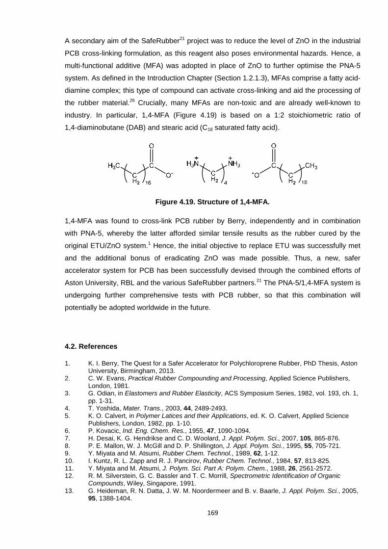
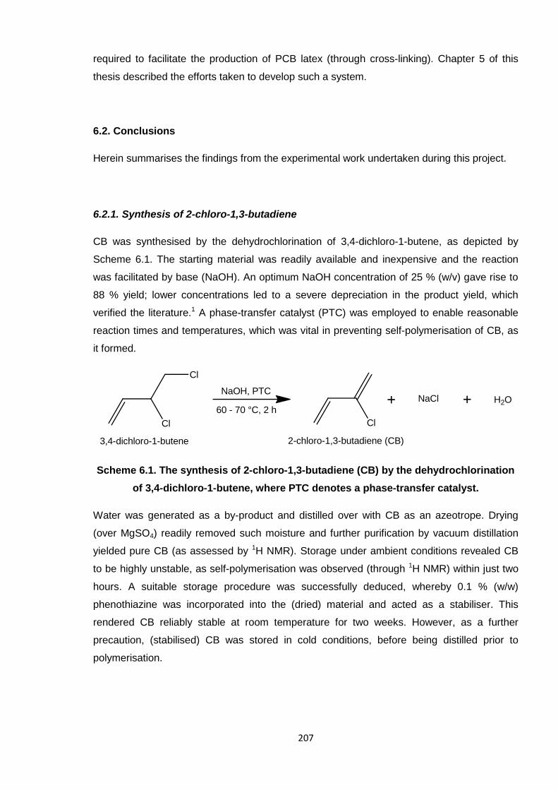
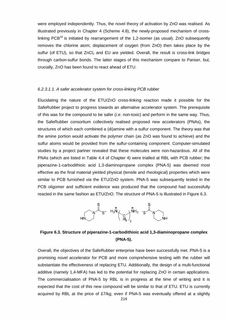
Poly(2-chloro-1,3-butadiene) (PCB, polychloroprene) has wide-ranging applications asneoprene rubber. Favourable chemical and physical properties in the material are attributedto a three-dimensional network of polymer chains, which is realised through cross-linking.Ethylene thiourea (ETU) and zinc oxide (ZnO) are the standard reagents which facilitate thisin industrial processes. However, ETU is a suspected carcinogen and its usage is due tobecome severely restricted, so much so that the future production of neoprene rubber is atrisk. Hence, an alternative, non-toxic cross-linking agent is required which can cross-linkPCB in the same fashion. The way in which the ETU/ZnO system functions must first beunderstood before a replacement can be proposed. Thus, mechanistic studies were initiallyundertaken with PCB oligomers in order to elucidate the reaction.
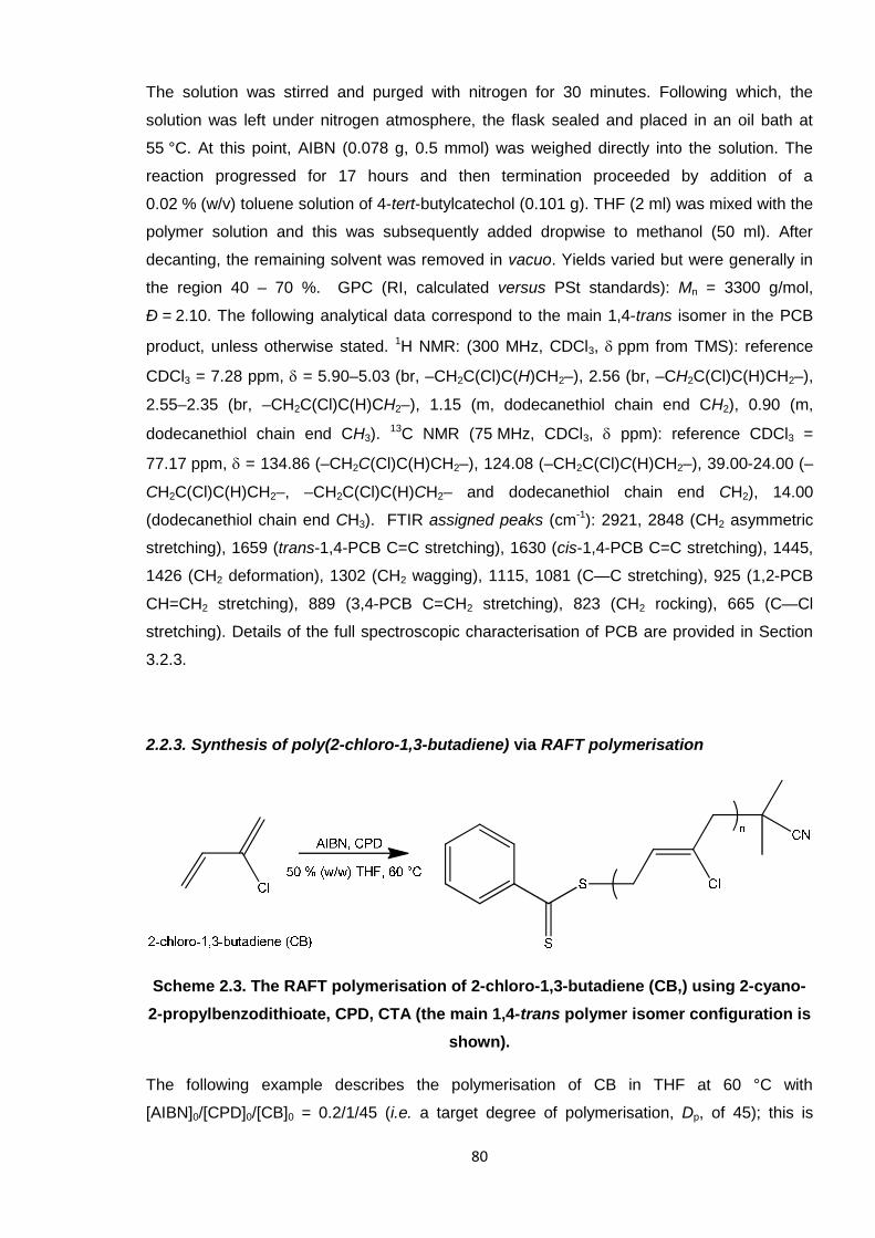
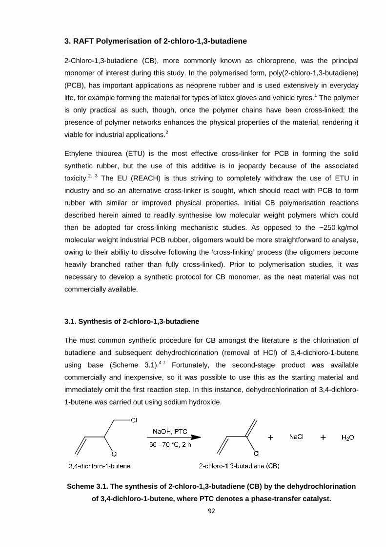
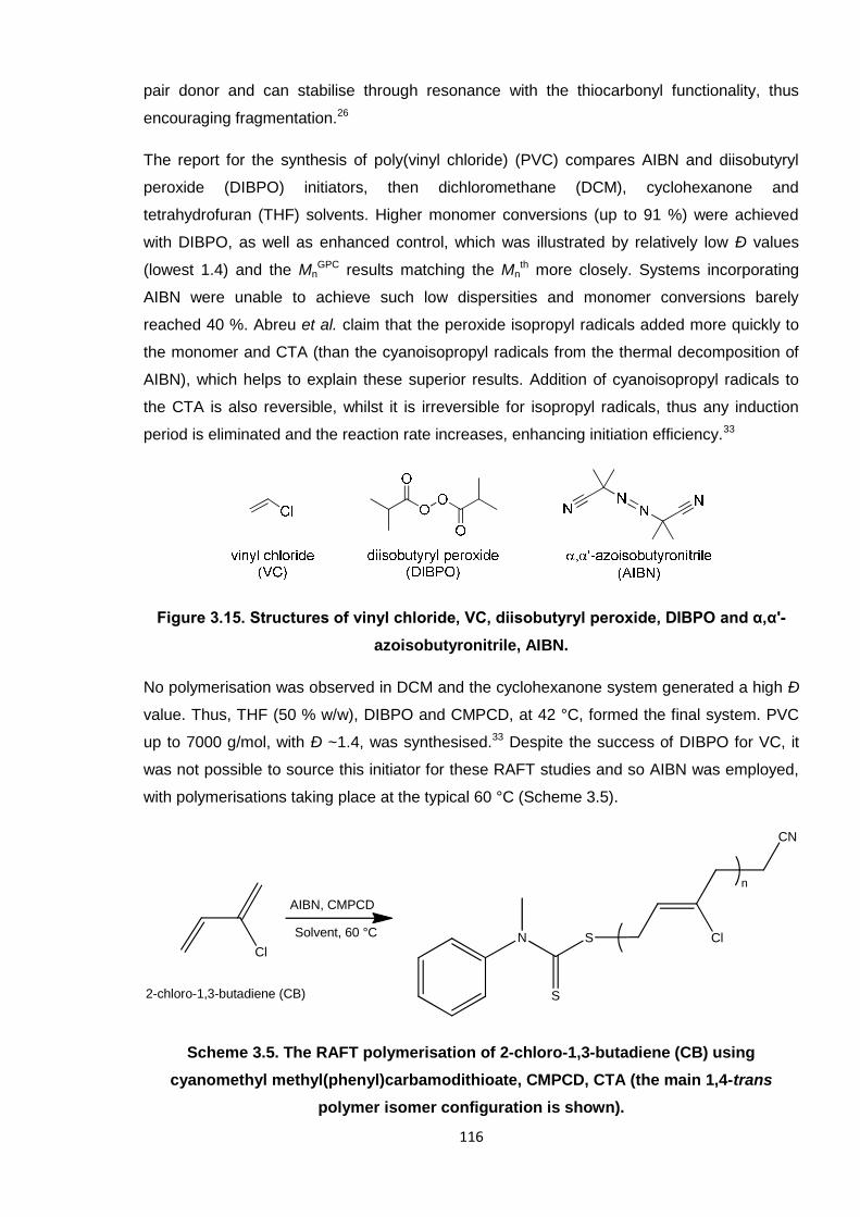
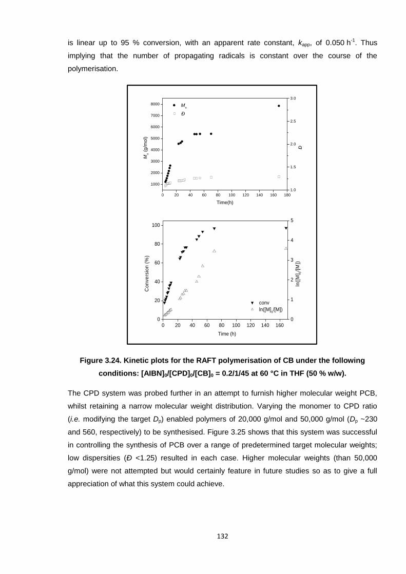
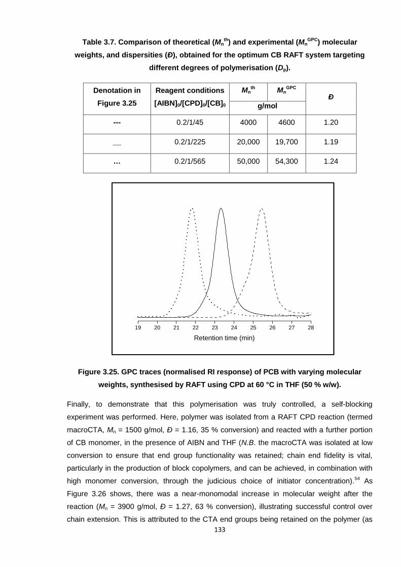
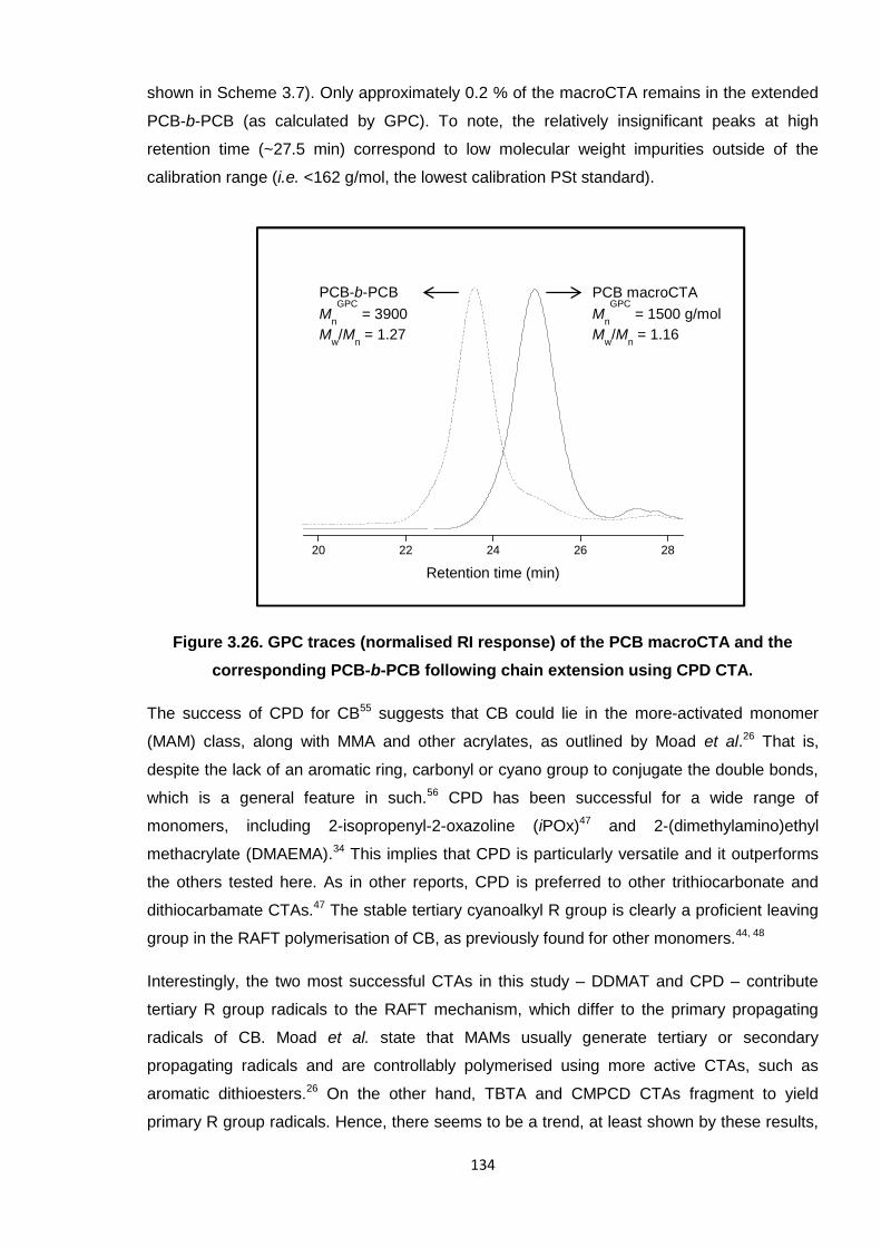
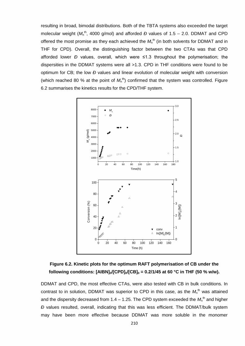
To this end, a synthetic protocol was established for 2-chloro-1,3-butadiene (CB) and themonomer was subsequently adopted in numerous polymerisation reactions. Investigationsinto the reversible addition-fragmentation chain transfer (RAFT) polymerisation of CBproceeded to predefine low molecular weight PCB. A successful procedure was realised,employing 2-cyano-2-propylbenzodithioate (CPD) CTA and conditions which were able tofurnish <1000 g/mol to 50,000 g/mol, low dispersity PCB in a controlled manner. Thisinvention was novel in that PCB has historically been synthesised via conventional(uncontrolled) free radical techniques.
PCB oligomers were adopted in cross-linking reactions with ETU and various modelcompounds, alone, and with ZnO, to aid the interpretation of the ETU/ZnO mechanism.Spectroscopic analyses and the observation of by-products revealed that three disparatereactions occur; ETU and ZnO were found to act both synergistically and independently ofeach other. A newly-proposed mechanism describes activation of the polymer chain by ZnOand subsequent reaction through sulfur. As a result of this discovery, alternative compoundshave been tested and found capable of cross-linking PCB.
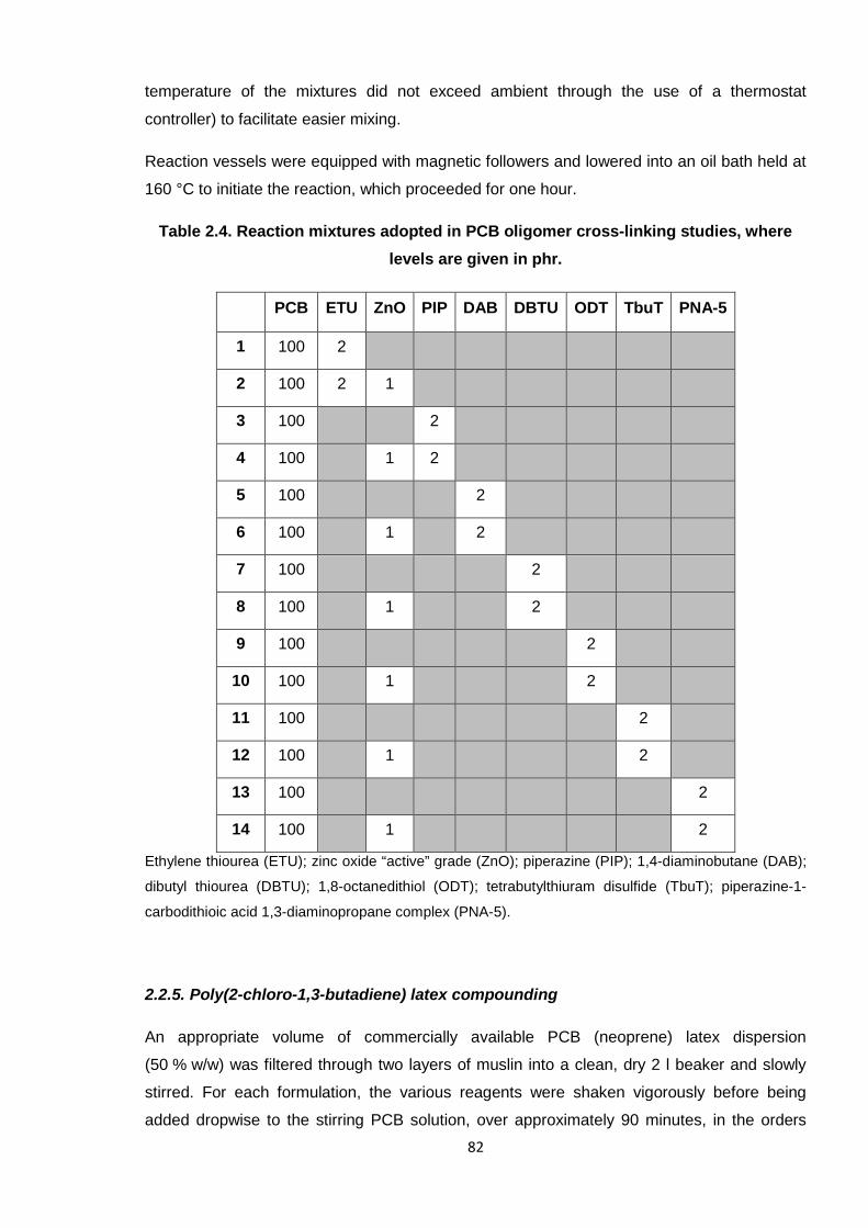
In a second industrial study, the eradication of allergy-causing cross-linking additives for PCBlatex (gloves) was investigated. PCB latex films were generated under various conditionsand the materials physically tested. A novel amine-dithiocarbamate complex, combined witha xanthogen polysulfide, afforded comparable properties in PCB latex and as such is apotential replacement system.
Paints polyacrylics, polybutadienes, PVAc, poly(vinyl ethers)*The final latex composition is often based on copolymers, rather than homopolymers; single polymers
are listed here to represent the primary constituent for each material in the given application.†The
principal polymer of NR is 1,4-cis-polyisoprene.‡Automotive parts include the tyres and seals.
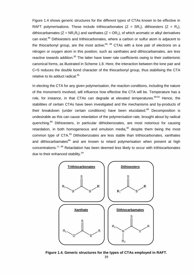
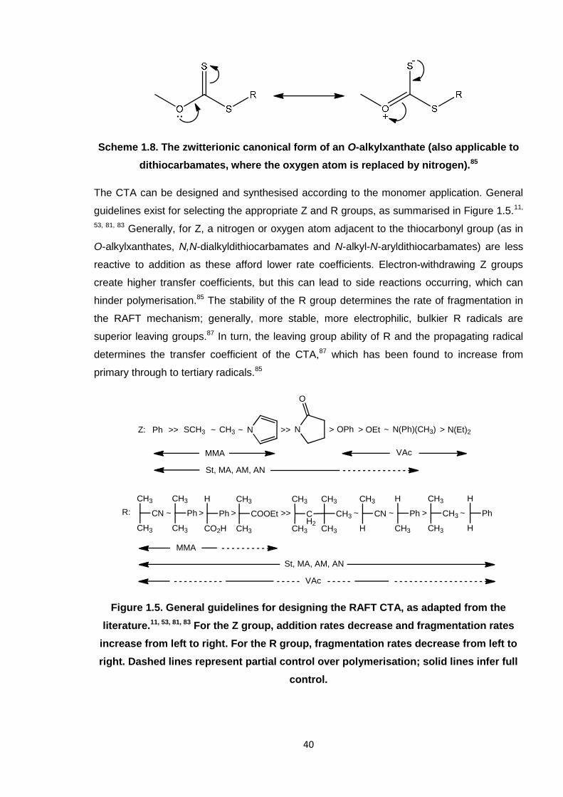
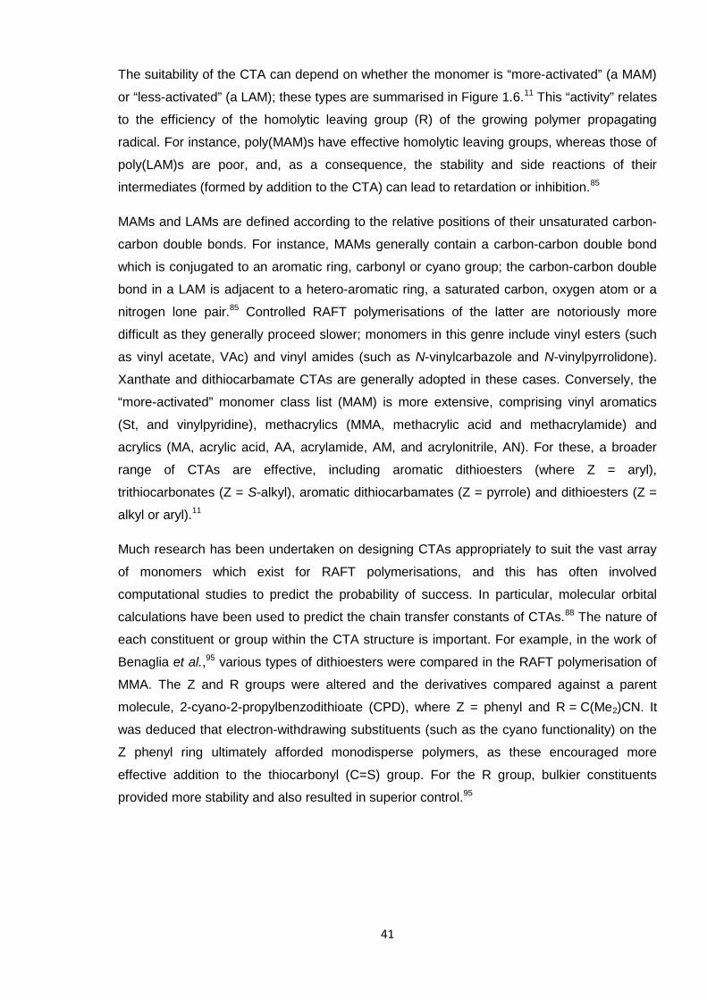
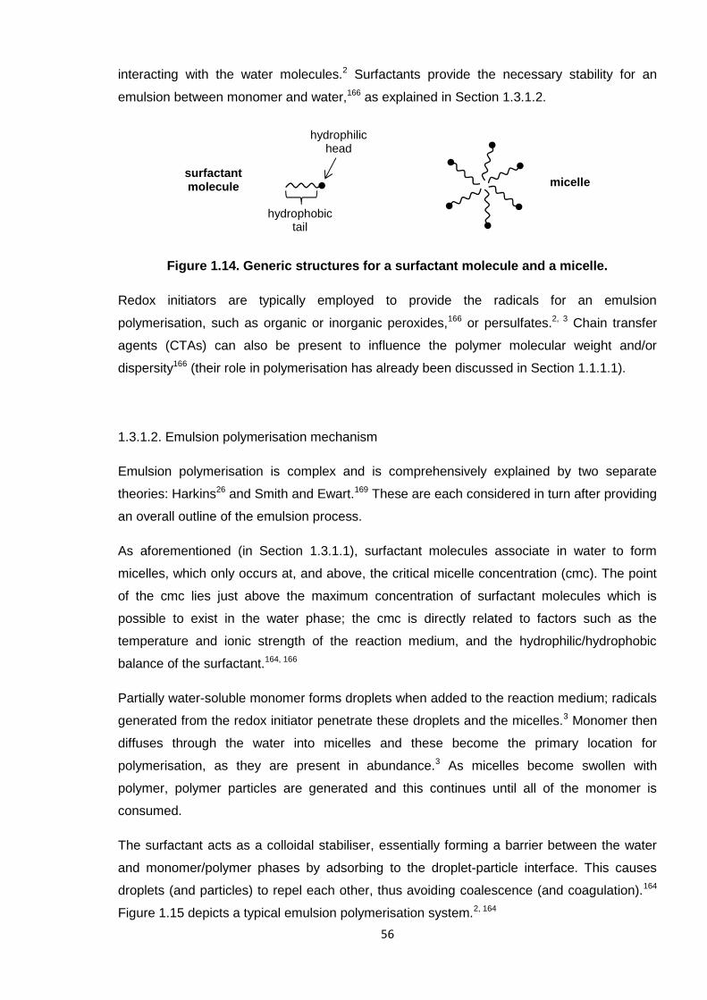
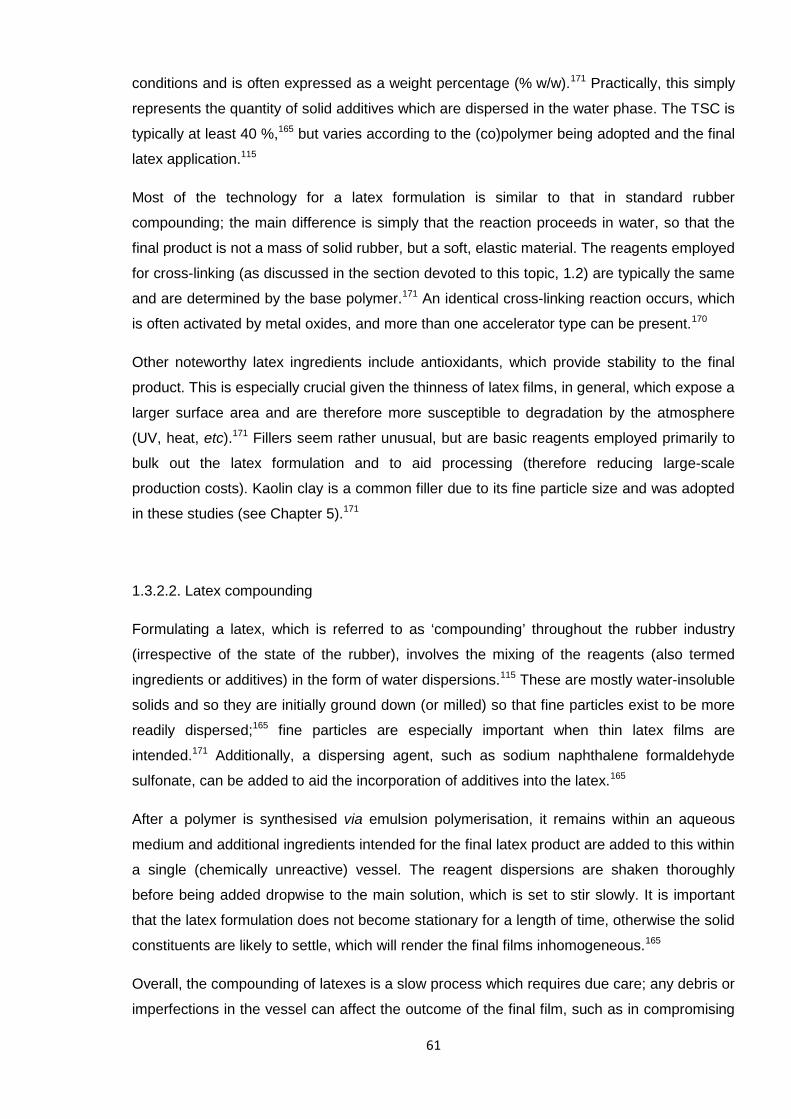
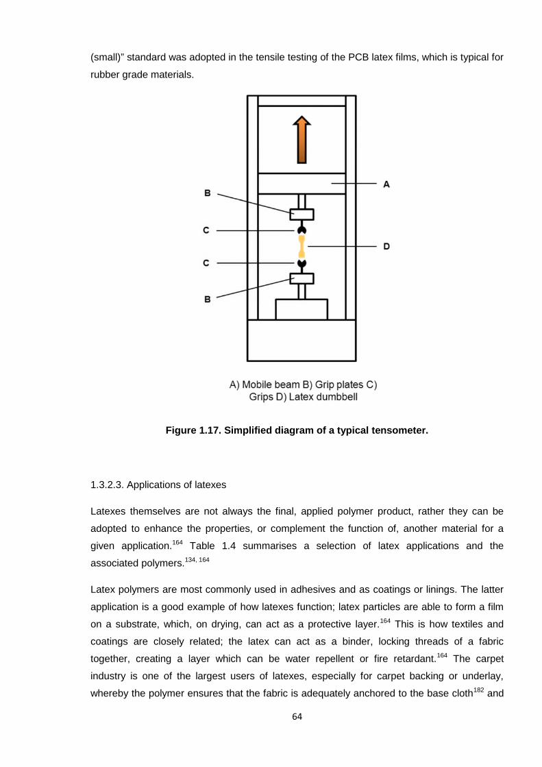
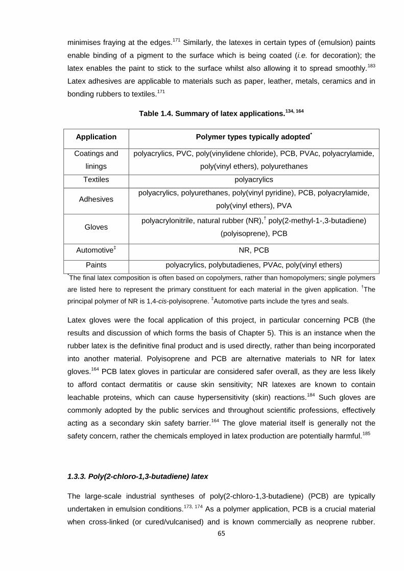
Latex gloves were the focal application of this project, in particular concerning PCB (the
results and discussion of which forms the basis of Chapter 5). This is an instance when the
rubber latex is the definitive final product and is used directly, rather than being incorporated
into another material. Polyisoprene and PCB are alternative materials to NR for latex
gloves.164 PCB latex gloves in particular are considered safer overall, as they are less likely
to afford contact dermatitis or cause skin sensitivity; NR latexes are known to contain
leachable proteins, which can cause hypersensitivity (skin) reactions.184 Such gloves are
commonly adopted by the public services and throughout scientific professions, effectively
acting as a secondary skin safety barrier.164 The glove material itself is generally not the
safety concern, rather the chemicals employed in latex production are potentially harmful.185
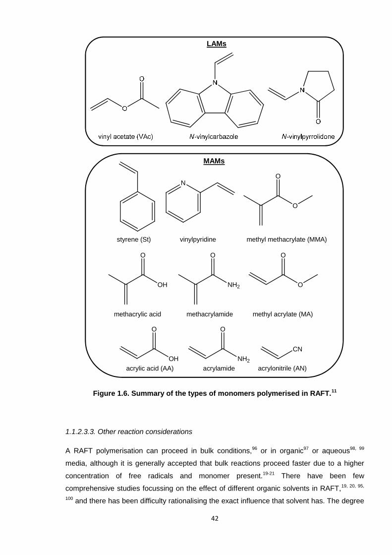
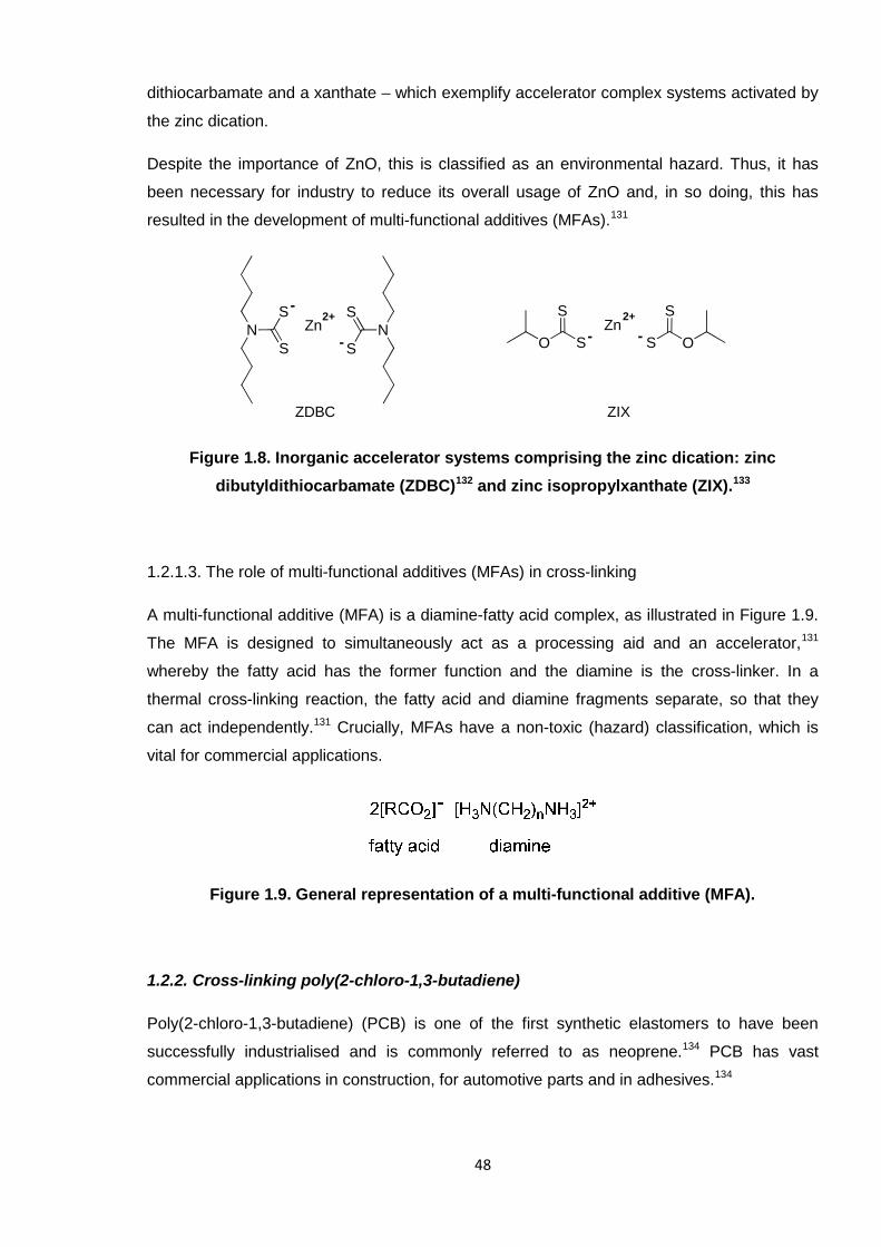
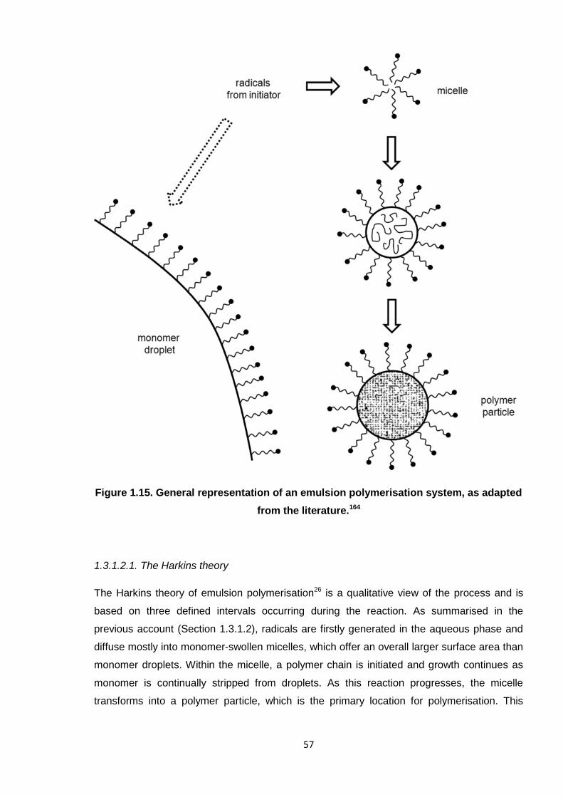
1.3.3. Poly(2-chloro-1,3-butadiene) latex
The large-scale industrial syntheses of poly(2-chloro-1,3-butadiene) (PCB) are typically
undertaken in emulsion conditions.173, 174 As a polymer application, PCB is a crucial material
when cross-linked (or cured/vulcanised) and is known commercially as neoprene rubber.
66
This section details the current standard additives for PCB rubber latex and outlines the
relevance to this project.
1.3.3.1. PCB latex composition
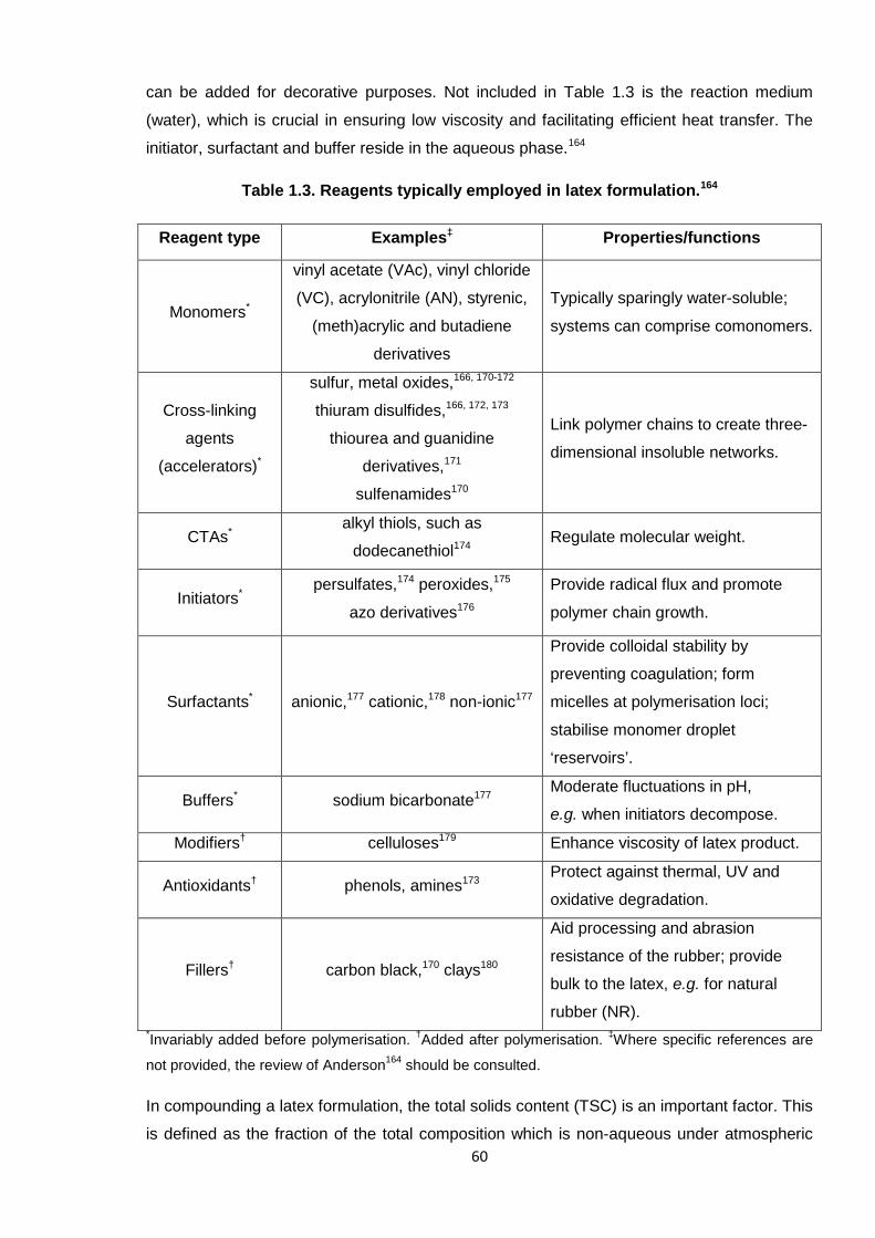
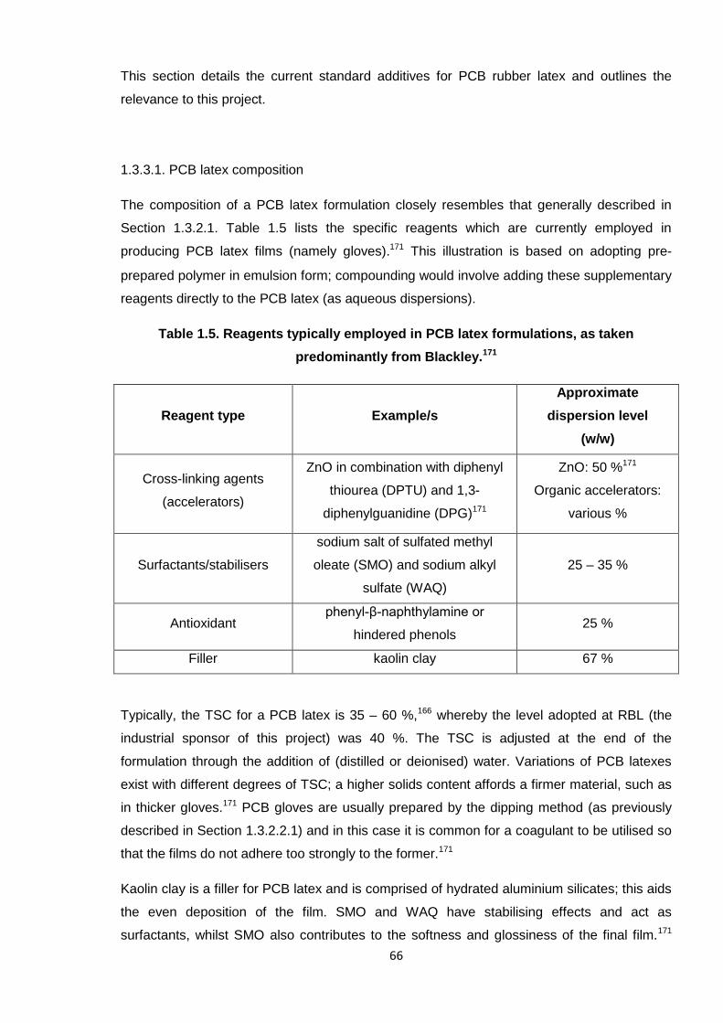
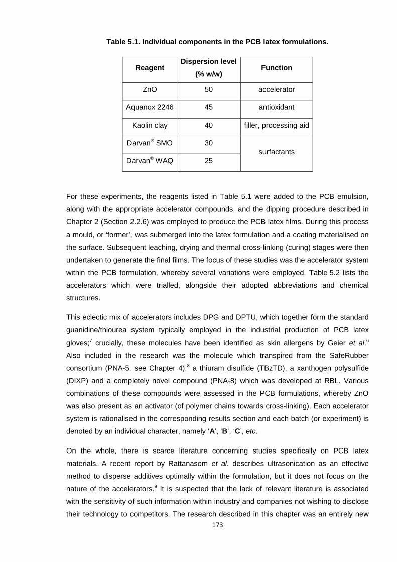
The composition of a PCB latex formulation closely resembles that generally described in
Section 1.3.2.1. Table 1.5 lists the specific reagents which are currently employed in
producing PCB latex films (namely gloves).171 This illustration is based on adopting pre-
prepared polymer in emulsion form; compounding would involve adding these supplementary
reagents directly to the PCB latex (as aqueous dispersions).
Table 1.5. Reagents typically employed in PCB latex formulations, as taken
predominantly from Blackley.171
Reagent type Example/s
Approximate
dispersion level
(w/w)
Cross-linking agents
(accelerators)
ZnO in combination with diphenyl
thiourea (DPTU) and 1,3-
diphenylguanidine (DPG)171
ZnO: 50 %171
Organic accelerators:
various %
Surfactants/stabilisers
sodium salt of sulfated methyl
oleate (SMO) and sodium alkyl
sulfate (WAQ)
25 – 35 %
Antioxidantphenyl-β-naphthylamine or
hindered phenols25 %
Filler kaolin clay 67 %
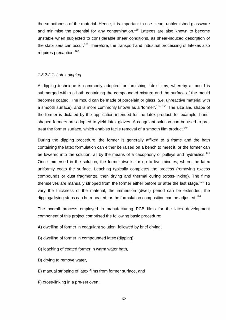
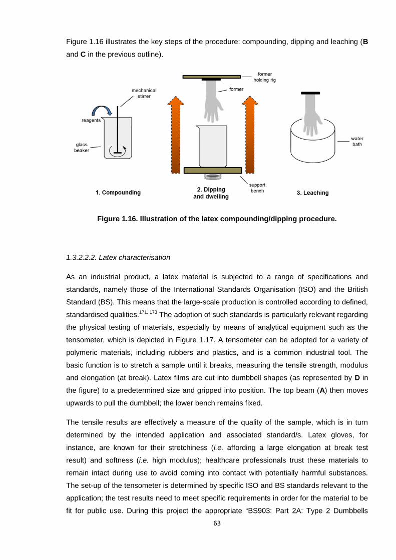
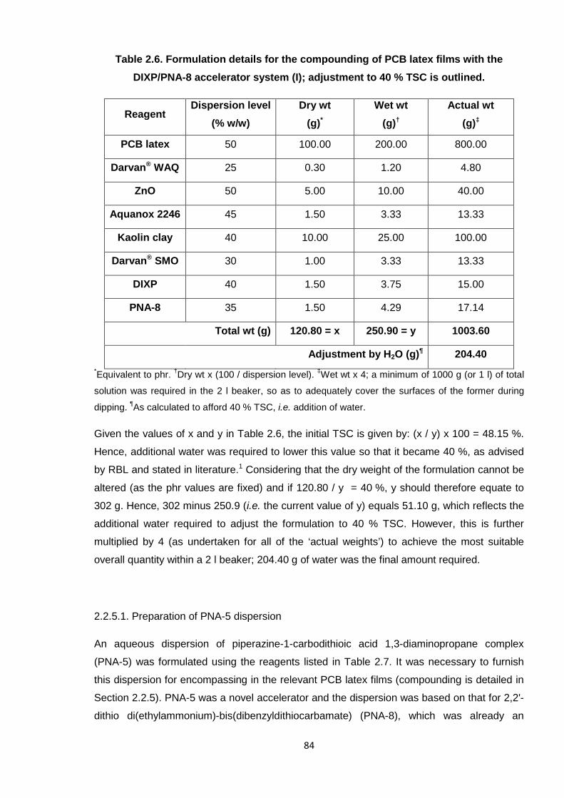
Typically, the TSC for a PCB latex is 35 – 60 %,166 whereby the level adopted at RBL (the
industrial sponsor of this project) was 40 %. The TSC is adjusted at the end of the
formulation through the addition of (distilled or deionised) water. Variations of PCB latexes
exist with different degrees of TSC; a higher solids content affords a firmer material, such as
in thicker gloves.171 PCB gloves are usually prepared by the dipping method (as previously
described in Section 1.3.2.2.1) and in this case it is common for a coagulant to be utilised so
that the films do not adhere too strongly to the former.171
Kaolin clay is a filler for PCB latex and is comprised of hydrated aluminium silicates; this aids
the even deposition of the film. SMO and WAQ have stabilising effects and act as
surfactants, whilst SMO also contributes to the softness and glossiness of the final film.171
67
The peculiar abbreviations ascribed to these additives were adopted by the supplier,
Vanderbilt Chemicals, USA, and are denoted DARVAN® SMO and DARVAN® WAQ in full.
The nature of the accelerators is discussed in the subsequent section (1.3.3.2), with a focus
on their associated hazards. DPTU and DPG are generally recognised as the standard
industrial accelerators for PCB latexes171 and these have been adopted at RBL. Other
accelerator types which have been studied include thiuram derivatives, dithiocarbamates and
thiazoles, as listed in Table 1.6 in Section 1.3.3.2.
1.3.3.2. PCB latex applications
PCB latexes are used in a wide variety of applications, such as in coatings, adhesives,
automotive parts and gloves.134, 164 The latter application is pertinent to this project and is
discussed in more detail herein.
PCB is a successful alternative to NR in latex gloves, as it does not cause harm to, or skin
sensitivity in, the end-user (due to the absence of proteins in the material).184 Attention has
thus shifted largely towards further verifying the safety of PCB latex gloves. A review by
Rose et al. summarises the various hazards associated with latex gloves in general and
identifies the offending chemicals to mostly be the accelerators used for cross-linking.186
Geier et al. has also summarised the results of patch tests performed on human subjects
with various types of accelerator and deduced that thiurams were the most harmful.187 The
particular compounds highlighted as potential allergens are shown in Table 1.6.
In some cases, it is not the parent molecule which poses the risk; thiazoles and sulfenamides
can liberate amines during cross-linking, which can subsequently leach out from the rubber
and thus potentially cause harm to the user.185 Similarly, thiuram disulfides can also liberate
amines, such as the particularly undesirable N-nitrosamine, which initiated the investigations
of Debnath and Basu.188 Notably, the majority of development concerning accelerator
systems has not been undertaken on the latexes themselves, but whilst adopting the solid
rubber equivalent, as this material is generally easier to handle and process.188
The work undertaken on PCB for this section of the project was performed on the latex
directly at RBL. These studies aimed to develop a safer accelerator system for the material,
with hopes to eradicate the health issues previously raised with latex gloves, in general. RBL
identified the standard PCB system to comprise the accelerators DPTU and DPG, i.e. known
allergens, as listed in Table 1.6. The aim here was to replace DPTU and DPG in the PCB
latex with safer alternatives, which is a similar enterprise to that of the oligomeric PCB cross-
68
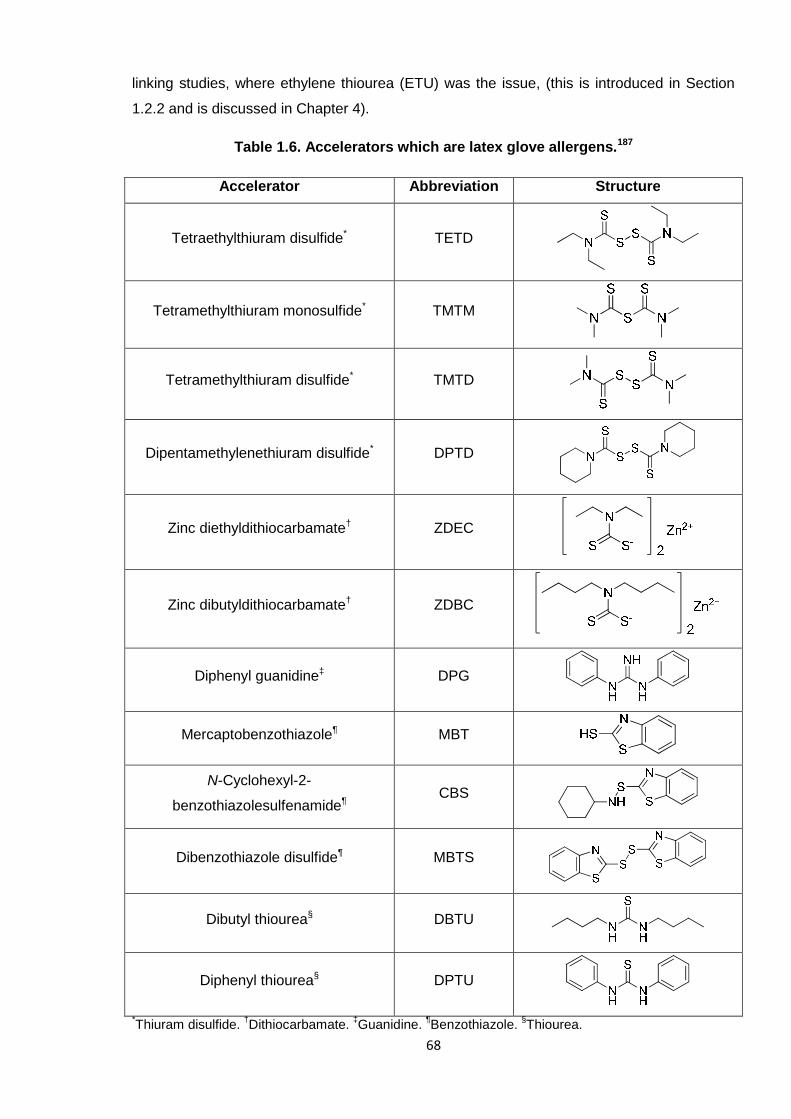
linking studies, where ethylene thiourea (ETU) was the issue, (this is introduced in Section
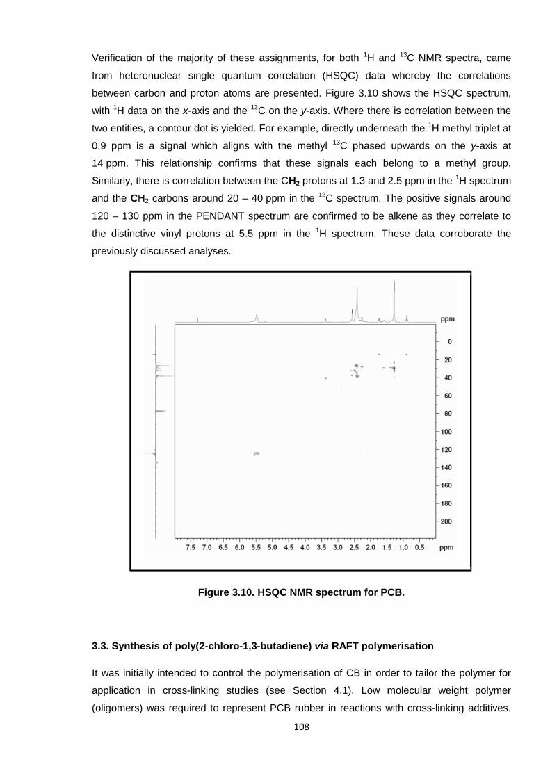
1.2.2 and is discussed in Chapter 4).
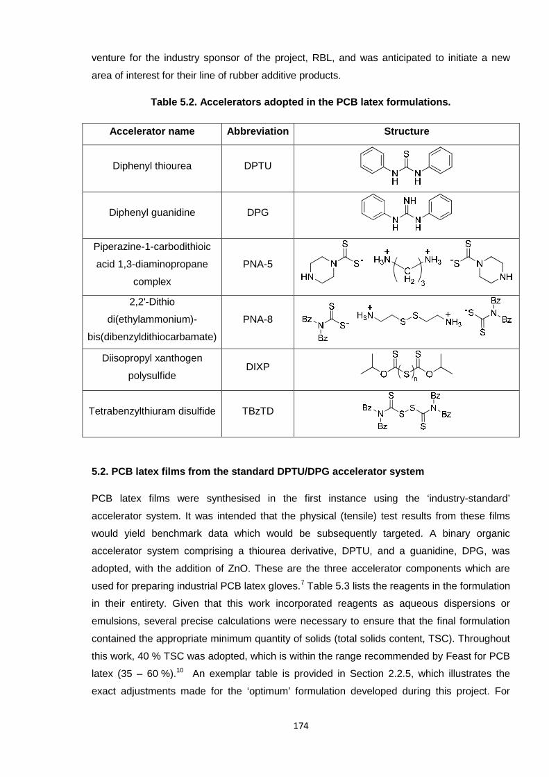
Table 1.6. Accelerators which are latex glove allergens.187
Accelerator Abbreviation Structure
Tetraethylthiuram disulfide* TETD
Tetramethylthiuram monosulfide* TMTM
Tetramethylthiuram disulfide* TMTD
Dipentamethylenethiuram disulfide* DPTD
Zinc diethyldithiocarbamate† ZDEC
Zinc dibutyldithiocarbamate† ZDBC
Diphenyl guanidine‡ DPG
Mercaptobenzothiazole¶ MBT
N-Cyclohexyl-2-
benzothiazolesulfenamide¶CBS
Dibenzothiazole disulfide¶ MBTS
Dibutyl thiourea§ DBTU
Diphenyl thiourea§ DPTU
*Thiuram disulfide.
†Dithiocarbamate.
‡Guanidine.
¶Benzothiazole.
§Thiourea.
69
There are few studies in the literature concerning the development of PCB latex; it is strongly
expected that industrial research teams have not necessarily publicised their work openly as
they wish to retain the Intellectual Property (IP) of their findings. One particular report,
however, does concern PCB latex but this focusses on using silica as a filler and optimises
the dispersion thereof by ultrasonication; this research was not concerned with altering the
standard DPTU/DPG accelerator system.170
It is common for systems to comprise two active organic accelerator compounds, i.e. they act
in a binary fashion. As described by Mathew et al.,189 and Debnath and Basu,188 accelerators
can complement, and be activated by, one another. For instance, thiazole-based derivatives,
such as CBS, MBT and MBTS, or thioureas, can work efficiently with thiuram disulfides.188, 189
Both of these particular studies, however, were concerned with NR and used selected
allergens (listed previously in Table 1.6).
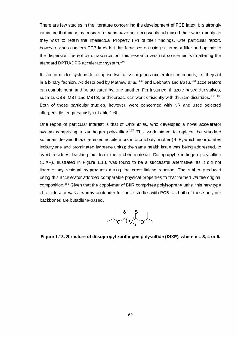
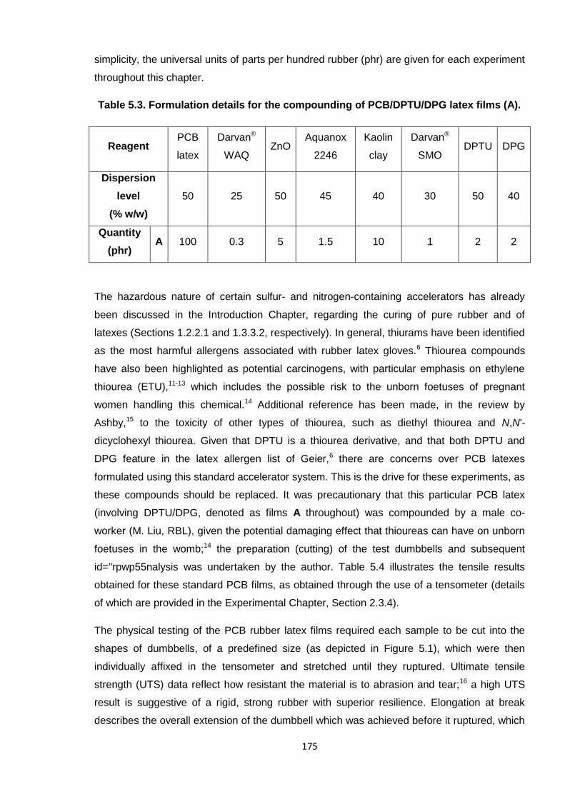
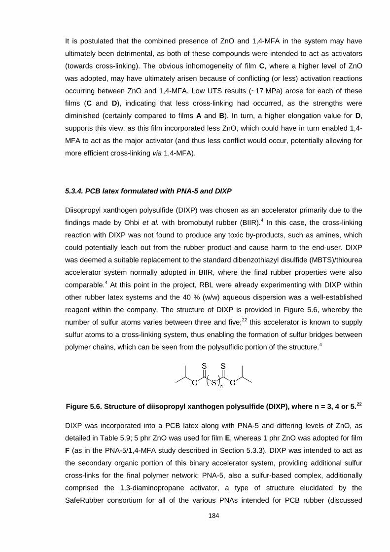
One report of particular interest is that of Ohbi et al., who developed a novel accelerator
system comprising a xanthogen polysulfide.185 This work aimed to replace the standard
sulfenamide- and thiazole-based accelerators in bromobutyl rubber (BIIR, which incorporates
isobutylene and brominated isoprene units); the same health issue was being addressed, to
avoid residues leaching out from the rubber material. Diisopropyl xanthogen polysulfide
(DIXP), illustrated in Figure 1.18, was found to be a successful alternative, as it did not
liberate any residual by-products during the cross-linking reaction. The rubber produced
using this accelerator afforded comparable physical properties to that formed via the original
composition.185 Given that the copolymer of BIIR comprises polyisoprene units, this new type
of accelerator was a worthy contender for these studies with PCB, as both of these polymer
backbones are butadiene-based.
Figure 1.18. Structure of diisopropyl xanthogen polysulfide (DIXP), where n = 3, 4 or 5.
70
1.4. Aims
Poly(2-chloro-13-butadiene) (PCB) exists as one of the most widely used elastomers,
boasting exceptional chemical and physical properties. Cross-linking introduces a three-
dimensional network into the polymer which ultimately affords the favourable properties of
this material; this is typically achieved through the use of ethylene thiourea (ETU). Concerns
have arisen regarding the carcinogenic nature of this compound and so an alternative
reagent was sought which should perform in the same way. The manner in which ETU cross-
links PCB has not been resolved; one of the objectives of the Europe-wide “SafeRubber”
campaign was to elucidate the reaction mechanism. Both low molecular weight polymer (i.e.
oligomers) and the PCB rubber was investigated separately by the author and K. Berry,
respectively. This collaborative effort characterised the cross-linking reactions physically,
through tensile testing, and using spectroscopic techniques; the use of oligomers was
anticipated to offer a greater insight into the chemistry taking place. In elucidating the
mechanism, the SafeRubber consortium looked to replace ETU in the cross-linking of PCB
with a non-toxic alternative.
PCB is synthesised industrially via conventional free radical polymerisation in emulsion
conditions, which cannot accurately and reproducibly predefine the molecular weight. The
initial objective of this PhD project was to design a controlled polymerisation system which
enabled the predetermination of low molecular weight PCB, which was subsequently
intended for cross-linking investigations. It was conceivable that reversible addition-
fragmentation chain transfer (RAFT) polymerisation would facilitate this, as it is arguably the
most versatile, straightforward controlled-radical technique. RAFT was a novel enterprise for
PCB, as this method had not been successfully adopted for this polymer to-date.
The second industrial contribution to this PhD project was in developing an alternative
accelerator system for PCB latex. Diphenyl thiourea (DPTU) and diphenyl guanidine (DPG)
are the standard compounds employed in the industrial production of PCB latex gloves, but
these chemicals are known allergens. Thus, this binary accelerator system should be
replaced by non-hazardous compounds which are able to yield PCB latex of a similar grade.
Investigations proceeded by furnishing various PCB latexes with alternative reagents and
assessing their relative performances in tensile tests.
71
1.5. References
1. G. Odian, Principles of Polymerization, Wiley Interscience, New York, 1991.2. B. M. Mandal, Fundamentals of Polymerization, World Scientific, Singapore, 2013.3. J. M. G. Cowie, Polymers: Chemistry & Physics of Modern Materials, Chapham & Hall, Bath,
1991.4. W. H. Carothers, Chem. Rev., 1931, 8, 353-426.5. J. I. Cunneen, E. H. Farmer and H. P. Koch, J. Chem. Soc., 1943, 472-476.6. US Pat., 4581429, 1986.7. M. Kato, M. Kamigaito, M. Sawamoto and T. Higashimura, Macromolecules, 1995, 28, 1721-
1723.8. J.-S. Wang and K. Matyjaszewski, J. Am. Chem. Soc., 1995, 117, 5614-5615.9. T. P. T. Le, G. Moad, E. Rizzardo and S. H. Thang, Chem. Abst., 1998, 128, 115390.10. C. J. Hawker, A. W. Bosman and E. Harth, Chem. Rev., 2001, 101, 3661-3688.11. G. Moad, E. Rizzardo and S. H. Thang, Acc. Chem. Res., 2008, 41, 1133-1142.12. M. P. Stevens, Polymer Chemistry: An Introduction, Oxford University Press, New York, 1990.13. J. P. Van Hook and A. V. Tobolsky, J. Am. Chem. Soc., 1958, 80, 779-782.14. D. R. Hensley, S. D. Goodrich, A. Y. Huckstep, H. J. Harwood and P. L. Rinaldi,
Macromolecules, 1995, 28, 1586-1591.15. J. Carraher, C. E., Introduction to Polymer Chemistry, Taylor and Francis Group, Boca Raton,
2010.16. F. R. Mayo, J. Am. Chem. Soc., 1943, 65, 2324-2329.17. G. Moad and D. H. Solomon, The Chemistry of Free Radical Polymerization, Elsevier Science,
Oxford, 1995.18. R. J. Young and P. A. Lovell, Introduction to Polymers, Chapman and Hall, London, 1991.19. R. P. Babu and R. Dhamodharan, Polym. Int., 2008, 57, 365-371.20. M. R. Wood, D. J. Duncalf, P. Findlay, S. P. Rannard and S. Perrier, Aust. J. Chem., 2007, 60,
772-778.21. S. Perrier and P. Takolpuckdee, J. Polym. Sci. Part A: Polym. Chem., 2005, 43, 5347-5393.22. M. Tatsumi and S. Yamamoto, Polym. Bull., 1983, 10, 452-457.23. S. Slomkowski, J. V. Aleman, R. G. Gilbert, M. Hess, K. Horie, R. G. Jones, P. Kubisa, I.
Meisel, W. Mormann, S. Penczek and R. F. T. Stepto, Pure Appl. Chem., 2011, 83, 2229-2259.
24. D. C. Blackley, Emulsion Polymerisation - Theory and Practice, Applied Science Publishers,London, 1975.
25. J. W. Vanderhoff, J. Polym. Sci. Polym. Sym., 1985, 72, 161-198.26. W. D. Harkins, J. Am. Chem. Soc., 1947, 69, 1428-1444.27. S. Schulze and H. Vogel, Chem. Eng. Technol., 1998, 21, 829-837.28. N. Pullan, M. Liu and P. D. Topham, Polym. Chem., 2013, 4, 2272-2277.29. P. D. Topham, N. Sandon, E. S. Read, J. Madsen, A. J. Ryan and S. P. Armes,
Macromolecules, 2008, 41, 9542-9547.30. C. E. Barnes, J. Am. Chem. Soc., 1945, 67, 217-220.31. M. Save, Y. Guillaneuf and R. G. Gilbert, Aust. J. Chem., 2006, 59, 693-711.32. M. Szwarc, M. Levy and R. Milkovich, J. Am. Chem. Soc., 1956, 78, 2656-2657.33. M. Szwarc, Die Makromolekulare Chemie, 1960, 35, 132-158.34. O. W. Webster, W. R. Hertler, D. Y. Sogah, W. B. Farnham and T. V. RajanBabu, J. Am.
Chem. Soc., 1983, 105, 5706-5708.35. W. R. Hertler, D. Y. Sogah, O. W. Webster and B. M. Trost, Macromolecules, 1984, 17, 1415-
1417.36. O. W. Webster, J. Polym. Sci. Part A: Polym. Chem., 2000, 38, 2855-2860.37. D. Y. Sogah, W. R. Hertler, O. W. Webster and G. M. Cohen, Macromolecules, 1987, 20,
1473-1488.38. D. M. Haddleton and M. C. Crossman, Macromol. Chem. Phys., 1997, 198, 871-881.39. A. D. Jenkins, E. Tsartolia, D. R. M. Walton, J. Horská-Jenkins, P. Kratochvíl and J. Stejskal,
Die Makromolekulare Chemie, 1990, 191, 2511-2520.40. C. S. Patrickios, W. R. Hertler, N. L. Abbott and T. A. Hatton, Macromolecules, 1994, 27, 930-
937.41. T. C. Krasia and C. S. Patrickios, Polymer, 2002, 43, 2917-2920.42. R. Zhuang and A. H. E. Mueller, Macromolecules, 1995, 28, 8043-8050.43. P. F. W. Simon and A. H. E. Müller, Macromolecules, 2001, 34, 6206-6213.44. C. N. Costa and C. S. Patrickios, J. Polym. Sci. Part A: Polym. Chem., 1999, 37, 1597-1607.45. J. Zhang, M. Wang, J. Wang, Y. Shi, J. Tao and D. Wang, Polym. Bull., 2005, 54, 157-161.
72
46. M. Eggert and R. Freitag, J. Polym. Sci. Part A: Polym. Chem., 1994, 32, 803-813.47. C. W. Bielawski and R. H. Grubbs, Prog. Polym. Sci., 2007, 32, 1-29.48. S. Aoshima and S. Kanaoka, Chem. Rev., 2009, 109, 5245-5287.49. N. E. Kamber, W. Jeong, R. M. Waymouth, R. C. Pratt, B. G. G. Lohmeijer and J. L. Hedrick,
Chem. Rev., 2007, 107, 5813-5840.50. K. Matyjaszewski and J. Xia, Chem. Rev., 2001, 101, 2921-2990.51. S. C. Farmer and T. E. Patten, J. Polym. Sci., Part A: Polym. Chem., 2002, 40, 555-563.52. T. B. Zheltonozhskaya, S. V. Fedorchuk and V. G. Syromyatnikov, Russ. Chem. Rev., 2007,
76, 731-765.53. G. Moad, E. Rizzardo and S. H. Thang, Aust. J. Chem., 2005, 58, 379-410.54. P. B. Zetterlund, Y. Kagawa and M. Okubo, Chem. Rev., 2008, 108, 3747-3794.55. S. Penczek and G. Moad, Pure Appl. Chem., 2008, 80, 2163-2193.56. P. J. MacLeod, R. Barber, P. G. Odell, B. Keoshkerian and M. K. Georges, Macromol. Symp.,
2000, 155, 31-38.57. L. I. Gabaston, R. A. Jackson and S. P. Armes, Macromolecules, 1998, 31, 2883-2888.58. P. Lacroix-Desmazes, P. Andre, J. M. Desimone, A.-V. Ruzette and B. Boutevin, J. Polym.
Sci. Part A: Polym. Chem., 2004, 42, 3537-3552.59. E. Bultz and T. P. Bender, Macromolecules, 2011, 44, 3666-3669.60. Y. Guo, M. E. Tysoe and P. B. Zetterlund, Polym. Chem., 2013, 4, 3256-3264.61. C. Detrembleur, C. Jerome, J. De Winter, P. Gerbaux, J.-L. Clement, Y. Guillaneuf and D.
Gigmes, Polym. Chem., 2014, 5, 335-340.62. C. Marestin, C. Noël, A. Guyot and J. Claverie, Macromolecules, 1998, 31, 4041-4044.63. D. Greszta and K. Matyjaszewski, J. Polym. Sci. Part A: Polym. Chem., 1997, 35, 1857-1861.64. D. S. Germack and K. L. Wooley, J. Polym. Sci., Part A: Polym. Chem., 2007, 45, 4100-4108.65. J. He, J. Chen, L. Li, J. Pan, C. Li, J. Cao, Y. Tao, F. Hua, Y. Yang, G. E. McKee and S.
Brinkmann, Polymer, 2000, 41, 4573-4577.66. K. Min, H. Gao and K. Matyjaszewski, Macromolecules, 2007, 40, 1789-1791.67. H. Fischer, J. Polym. Sci. Part A: Polym. Chem., 1999, 37, 1885-1901.68. W. Jakubowski, K. Min and K. Matyjaszewski, Macromolecules, 2005, 39, 39-45.69. J. Xia and K. Matyjaszewski, Macromolecules, 1997, 30, 7692-7696.70. G. Moineau, P. Dubois, R. Jérôme, T. Senninger and P. Teyssié, Macromolecules, 1998, 31,
545-547.71. W. Jakubowski and K. Matyjaszewski, Macromolecules, 2005, 38, 4139-4146.72. H. Tang, M. Radosz and Y. Shen, Macromol. Rapid Commun., 2006, 27, 1127-1131.73. H. Dong, W. Tang and K. Matyjaszewski, Macromolecules, 2007, 40, 2974-2977.74. W. Jakubowski, B. Kirci-Denizli, R. R. Gil and K. Matyjaszewski, Macromol. Chem. Phys.,
2008, 209, 32-39.75. A. Simakova, S. E. Averick, D. Konkolewicz and K. Matyjaszewski, Macromolecules, 2012, 45,
6371-6379.76. K. Mukumoto, Y. Wang and K. Matyjaszewski, ACS Macro Lett., 2012, 1, 599-602.77. X.-h. Liu, J. Wang, F.-j. Zhang, S.-l. An, Y.-l. Ren, Y.-h. Yu, P. Chen and S. Xie, J. Polym. Sci.
Part A: Polym. Chem., 2012, 50, 4358-4364.78. G. Zhu, L. Zhang, Z. Zhang, J. Zhu, Y. Tu, Z. Cheng and X. Zhu, Macromolecules, 2011, 44,
3233-3239.79. S. Perrier, P. Takolpuckdee, J. Westwood and D. M. Lewis, Macromolecules, 2004, 37, 2709-
2717.80. J. B. McLeary and B. Klumperman, Soft Matter, 2006, 2, 45-53.81. G. Moad, E. Rizzardo and S. H. Thang, Aust. J. Chem., 2009, 62, 1402-1472.82. J. Chiefari, Y. K. Chong, F. Ercole, J. Krstina, J. Jeffery, T. P. T. Le, R. T. A. Mayadunne, G.
F. Mejis, C. L. Moad, G. Moad, E. Rizzardo and S. H. Thang, Macromolecules, 1998, 31,5559-5562.
83. G. Moad, E. Rizzardo and S. H. Thang, Aust. J. Chem., 2006, 59, 669-692.84. G. Moad, E. Rizzardo and S. H. Thang, Polymer, 2008, 49, 1079-1131.85. D. J. Keddie, G. Moad, E. Rizzardo and S. H. Thang, Macromolecules, 2012, 45, 5321-5342.86. E. Rizzardo, J. Chiefari, Y. K. Chong, F. Ercole, J. Krstina, J. Jeffery, T. P. T. Le, R. T. A.
Mayadunne, G. F. Mejis, C. L. Moad, G. Moad and S. H. Thang, Macromol. Symp., 1999, 143,291-307.
87. Y. K. Chong, J. Krstina, T. P. T. Le, G. Moad, A. Postma, E. Rizzardo and S. H. Thang,Macromolecules, 2003, 36, 2256-2272.
88. J. Chiefari, R. T. A. Mayadunne, C. L. Moad, G. Moad, E. Rizzardo, A. Postma, M. A.Skidmore and S. H. Thang, Macromolecules, 2003, 36, 2273-2283.
89. Y. Zhou, J. He, C. Li, L. Hong and Y. Yang, Macromolecules, 2011, 44, 8446-8457.
73
90. V. Jitchum and S. Perrier, Macromolecules, 2007, 40, 1408-1412.91. B. Chong, G. Moad, E. Rizzardo, M. A. Skidmore and S. H. Thang, Aust. J. Chem., 2006, 59,
755-762.92. J. Xu, J. He, D. Fan, W. Tang and Y. Yang, Macromolecules, 2006, 39, 3753-3759.93. C. Li and B. C. Benicewicz, J. Polym. Sci., Part A: Polym. Chem., 2005, 43, 1535-1543.94. O. I. Strube, L. Nothdurft, M. Drache and G. Schmidt-Naake, Macromol. Chem. Phys., 2011,
212, 574-582.95. M. Benaglia, E. Rizzardo, A. Alberti and M. Guerra, Macromolecules, 2005, 38, 3129-3140.96. A. Goto, K. Sato, Y. Tsujii, T. Fukuda, G. Moad, E. Rizzardo and S. H. Thang,
Macromolecules, 2001, 34, 402-408.97. M. H. Allen, S. T. Hemp, A. E. Smith and T. E. Long, Macromolecules, 2012, 45, 3669-3676.98. C. J. Ferguson, R. J. Hughes, B. T. T. Pham, B. S. Hawkett, R. G. Gilbert, A. K. Serelis and C.
H. Such, Macromolecules, 2002, 35, 9243-9245.99. S. W. Prescott, M. J. Ballard, E. Rizzardo and R. G. Gilbert, Macromolecules, 2002, 35, 5417-
5425.100. C. J. Dürr, S. G. J. Emmerling, A. Kaiser, S. Brandau, A. K. T. Habicht, M. Klimpel and C.
Barner-Kowollik, J. Polym. Sci. Part A: Polym. Chem., 2012, 50, 174-180.101. J. Jennings, M. Beija, J. T. Kennon, H. Willcock, R. K. O’Reilly, S. Rimmer and S. M. Howdle,
Macromolecules, 2013, 46, 6843-6851.102. J. Jennings, M. Beija, A. P. Richez, S. D. Cooper, P. E. Mignot, K. J. Thurecht, K. S. Jack and
S. M. Howdle, J. Am. Chem. Soc., 2012, 134, 4772-4781.103. J. Zhou, S. Villarroya, W. Wang, M. F. Wyatt, C. J. Duxbury, K. J. Thurecht and S. M. Howdle,
Macromolecules, 2006, 39, 5352-5358.104. H. M. Woods, M. M. C. G. Silva, C. Nouvel, K. M. Shakesheff and S. M. Howdle, J. Mater.
Chem., 2004, 14, 1663-1678.105. S. Kanagasabapathy, A. Sudalai and B. C. Benicewicz, Macromol. Rapid Commun., 2001, 22,
1076-1080.106. J. B. McLeary, F. M. Calitz, J. M. McKenzie, M. P. Tonge, R. D. Sanderson and B.
Klumperman, Macromolecules, 2004, 37, 2383-2394.107. S. E. Shim, H. Lee and S. Choe, Macromolecules, 2004, 37, 5565-5571.108. T. Arita, M. Buback and P. Vana, Macromolecules, 2005, 38, 7935-7943.109. J. D. Flores, J. Shin, C. E. Hoyle and C. L. McCormick, Polym. Chem., 2010, 1, 213-220.110. A. J. Convertine, N. Ayres, C. W. Scales, A. B. Lowe and C. L. McCormick,
Biomacromolecules, 2004, 5, 1177-1180.111. J. F. Quinn, E. Rizzardo and T. P. Davis, Chem. Commun., 2001, 1044-1045.112. A. Favier and M.-T. Charreyre, Macromol. Rapid Commun., 2006, 27, 653-692.113. J. Rzayev and J. Penelle, Angew. Chem., 2004, 116, 1723-1726.114. J. Rzayev and J. Penelle, Macromolecules, 2002, 35, 1489-1490.115. C. M. Blow and C. Hepburn, eds., Rubber Technology and Manufacture, Butterworths,
London, 1982.116. C. D. Vo, D. Kuckling, H. J. P. Adler and M. Schönhoff, Colloid Polym Sci, 2002, 280, 400-
409.117. H. A. Khonakdar, J. Morshedian, U. Wagenknecht and S. H. Jafari, Polymer, 2003, 44, 4301-
4309.118. X.-R. Zeng and T.-M. Ko, J. Appl. Polym. Sci., 1998, 67, 2131-2140.119. J.-M. Charrier, Polymeric Materials and Processing: Plastics, Elastomers and Composites,
Hanser, New York, 1990.120. M. Krumova, D. López, R. Benavente, C. Mijangos and J. M. Pereña, Polymer, 2000, 41,
9265-9272.121. W. Huang, G. L. Baker and M. L. Bruening, Angew. Chem., 2001, 113, 1558-1560.122. H. L. Fisher, Ind. Eng. Chem. Res., 1939, 31, 1381-1389.123. L. D. Loan, J. Polym. Sci., Part A: Gen. Pap., 1964, 2, 3053-3066.124. C. Jiao, Z. Wang, Z. Gui and Y. Hu, Eur. Polym. J., 2005, 41, 1204-1211.125. A. Oshima, S. Ikeda, E. Katoh and Y. Tabata, Radiat. Phys. Chem., 2001, 62, 39-45.126. M. N. Ismail, M. S. Ibrahim and M. A. Abd El-Ghaffar, Polym. Degrad. Stabil., 1998, 62, 337-
341.127. N. Rattanasom, T. Saowapark and C. Deeprasertkul, Polym. Test., 2007, 26, 369-377.128. S. Dasgupta, S. L. Agrawal, S. Bandyopadhyay, S. Chakraborty, R. Mukhopadhyay, R. K.
Malkani and S. C. Ameta, Polym. Test., 2008, 27, 277-283.129. G. Heideman, R. N. Datta, J. W. M. Noordermeer and B. v. Baarle, J. Appl. Polym. Sci., 2005,
95, 1388-1404.
74
130. G. Heideman, R. N. Datta and J. W. M. Noordermeer, Rubber Chem. Technol., 2004, 77, 512-541.
131. G. Heideman, J. W. M. Noordermeer and R. N. Datta, Rubber Chem. Technol., 2006, 79, 561-588.
132. J. K. Kurian, N. R. Peethambaran, K. C. Mary and B. Kuriakose, J. Appl. Polym. Sci., 2000,78, 304-310.
133. S. Palaty and R. Joseph, J. Appl. Polym. Sci., 2000, 78, 1769-1775.134. H. Ulrich, Introduction to Industrial Polymers, Hanser, Munich, 1993.135. R. C. Ferguson, J. Polym. Sci., Part A: Gen. Pap., 1964, 2, 4735-4741.136. P. R. Johnson, Rubber Chem. Technol., 1976, 49, 650-702.137. H. Desai, K. G. Hendrikse and C. D. Woolard, J. Appl. Polym. Sci., 2007, 105, 865-876.138. P. E. Mallon, W. J. McGill and D. P. Shillington, J. Appl. Polym. Sci., 1995, 55, 705-721.139. Y. Miyata and M. Atsumi, Rubber Chem. Technol., 1989, 62, 1-12.140. I. Kuntz, R. L. Zapp and R. J. Pancirov, Rubber Chem. Technol., 1984, 57, 813-825.141. Y. Miyata and M. Atsumi, J. Polym. Sci. Part A: Polym. Chem., 1988, 26, 2561-2572.142. L. Krause and M. A. Whitehead, Mol. Phys., 1973, 25, 99-111.143. SafeRubber, http://www.saferubber.eu/, Accessed 11/03/2014.144. D. M. Smith, Occup. Med., 1976, 26, 92-94.145. D. M. Smith, Br. J. Ind. Med., 1984, 41, 362-366.146. R. S. Chhabra, S. Eustis, J. K. Haseman, P. J. Kurtz and B. D. Carlton, Fundam. Appl.
Toxicol., 1992, 18, 405-417.147. J. Ashby, Mutagenesis, 1986, 1, 3-16.148. S. L. Graham, W. H. Hansen, K. J. Davis and C. H. Perry, J. Agric. Food Chem., 1973, 21,
324-329.149. S. L. Graham and W. H. Hansen, Bull. Environ. Contam. Toxicol., 1972, 7, 19-25.150. S. L. Graham, K. J. Davis, W. H. Hansen and C. H. Graham, Food Cos. Toxicol., 1975, 13,
493-499.151. T. Iwase, M. Yamamoto, M. Shirai, F. Akahori, T. Masaoka, T. Takizawa, K. Arishima and Y.
Eguchi, J. Vet. Med. Sci., 1997, 59, 59-61.152. K. I. Berry, The Quest for a Safer Accelerator for Polychloroprene Rubber, PhD Thesis, Aston
University, Birmingham, 2013.153. M. Guzmán, B. Vega, N. Agulló, U. Giese and S. Borrós, Rubber Chem. Technol., 2012, 85,
38-55.154. M. Guzmán, B. Vega, N. Agulló and S. Borrós, Rubber Chem. Technol., 2012, 85, 56-67.155. R. Vukov, Rubber Chem. Technol., 1984, 57, 284-290.156. F. P. Baldwin, D. J. Buckley, I. Kuntz and S. B. Robinson, Rubber Plast. Age, 1961, 42, 500-
510.157. K. G. Hendrikse, W. J. McGill, J. Reedijk and P. J. Nieuwenhuizen, J. Appl. Polym. Sci., 2000,
78, 2290-2301.158. K. G. Hendrikse and W. J. McGill, J. Appl. Polym. Sci., 2000, 78, 2302-2310.159. K. G. Hendrikse and W. J. McGill, J. Appl. Polym. Sci., 2001, 79, 1309-1316.160. A. S. Aprem, K. Joseph and S. Thomas, Rubber Chem. Technol., 2005, 78, 458-488.161. P. Kovacic, Ind. Eng. Chem. Res., 1955, 47, 1090-1094.162. Y. Xue, Z. Chen and H. L. Frisch, J. Appl. Polym. Sci., 1994, 51, 1353-1355.163. R. Pariser, Kunststoffe, 1960, 50, 623-627.164. C. D. Anderson and E. S. Daniels, RAPRA Review Reports, 2003, 14, Report 160.165. K. O. Calvert, in Polymer Latices and their Applications, ed. K. O. Calvert, Applied Science
Publishers, London, 1982, pp. 1-10.166. A. A. J. Feast, in Polymer Latices and their Applications, ed. K. O. Calvert, Applied Science
Publishers, London, 1982, pp. 21-46.167. H. Hopff and I. Fakla, Br. Polym. J., 1970, 2, 40-44.168. B. Emlie, C. Pichot and J. Guillot, Die Makromolekulare Chemie, 1991, 192, 1629-1647.169. W. V. Smith and R. H. Ewart, J. Chem. Phys., 1948, 16, 592-599.170. N. Rattanasom, P. Kueseng and C. Deeprasertkul, J. Appl. Polym. Sci., 2012, 124, 2657-
2668.171. D. C. Blackley, High Polymer Latices - Their Science and Technology. Volume 2: Testing and
Applications, Maclaren & Sons Ltd., London, 1966.172. K. O. Calvert, in Polymer Latices and their Applications, ed. K. O. Calvert, Applied Science
Publishers, London, 1982, pp. 11-20.173. K. O. Calvert, in Polymer Latices and their Applications, ed. K. O. Calvert, Applied Science
Publishers, London, 1982, pp. 47-69.174. K. Itoyama, N. Hirashima, J. Hirano and T. Kadowaki, Polym. J., 1991, 23, 859-864.
75
175. J. E. L. Joensson, H. Hassander, L. H. Jansson and B. Toernell, Macromolecules, 1991, 24,126-131.
176. J. L. Luna-Xavier, A. Guyot and E. Bourgeat-Lami, J. Colloid. Interface Sci., 2002, 250, 82-92.177. G. Pan, L. Wu, Z. Zhang and D. Li, J. Appl. Polym. Sci., 2002, 83, 1736-1743.178. H.-H. Chu and H.-Y. Hwang, Polym. Bull., 1997, 38, 295-302.179. K. Dimic-Misic, P. A. C. Gane and J. Paltakari, Ind. Eng. Chem. Res., 2013, 52, 16066-16083.180. S. Varghese and J. Karger-Kocsis, Polymer, 2003, 44, 4921-4927.181. S. H. Chang and I. J. Chung, Macromolecules, 1991, 24, 567-571.182. D. Porter, in Polymer Latices and their Applications, ed. K. O. Calvert, Applied Science
Publishers, London, 1982, pp. 71-91.183. K. Sellars and G. R. Brown, in Polymer Latices and their Applications, ed. K. O. Calvert,
Applied Science Publishers, London, 1982, pp. 145-171.184. S. H. Wakelin and I. R. White, Clin. Exp. Dermatol., 1999, 24, 245-248.185. D. S. Ohbi, T. S. Purewal, T. Shah and E. Siores, J. Appl. Polym. Sci., 2007, 106, 526-533.186. R. F. Rose, P. Lyons, H. Horne and S. M. Wilkinson, Contact Dermatitis, 2009, 61, 129-137.187. J. Geier, H. Lessmann, W. Uter and A. Schnuch, Contact Dermatitis, 2003, 48, 39-44.188. S. C. Debnath and D. K. Basu, J. Appl. Polym. Sci., 1996, 60, 845-855.189. C. Mathew, V. T. E. Mini, A. P. Kuriakose and D. J. Francis, J. Appl. Polym. Sci., 1994, 54,
1033-1041.
76
CHAPTER 2
MATERIALS AND EXPERIMENTAL
METHODS
77
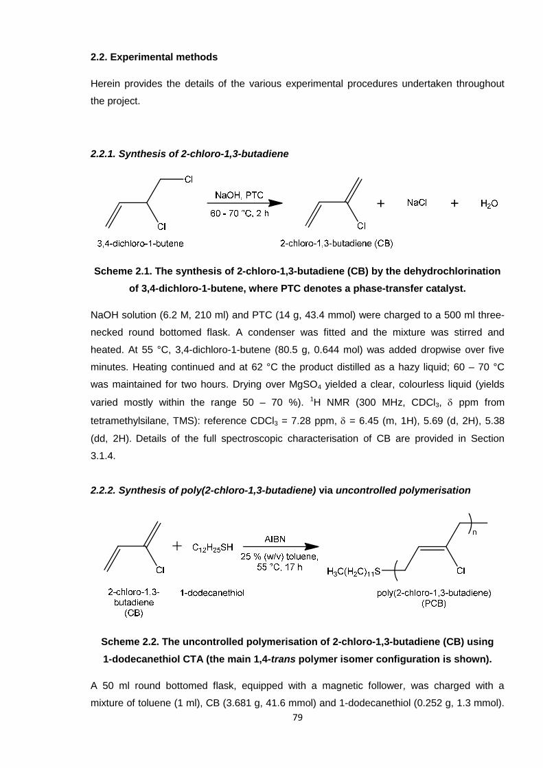
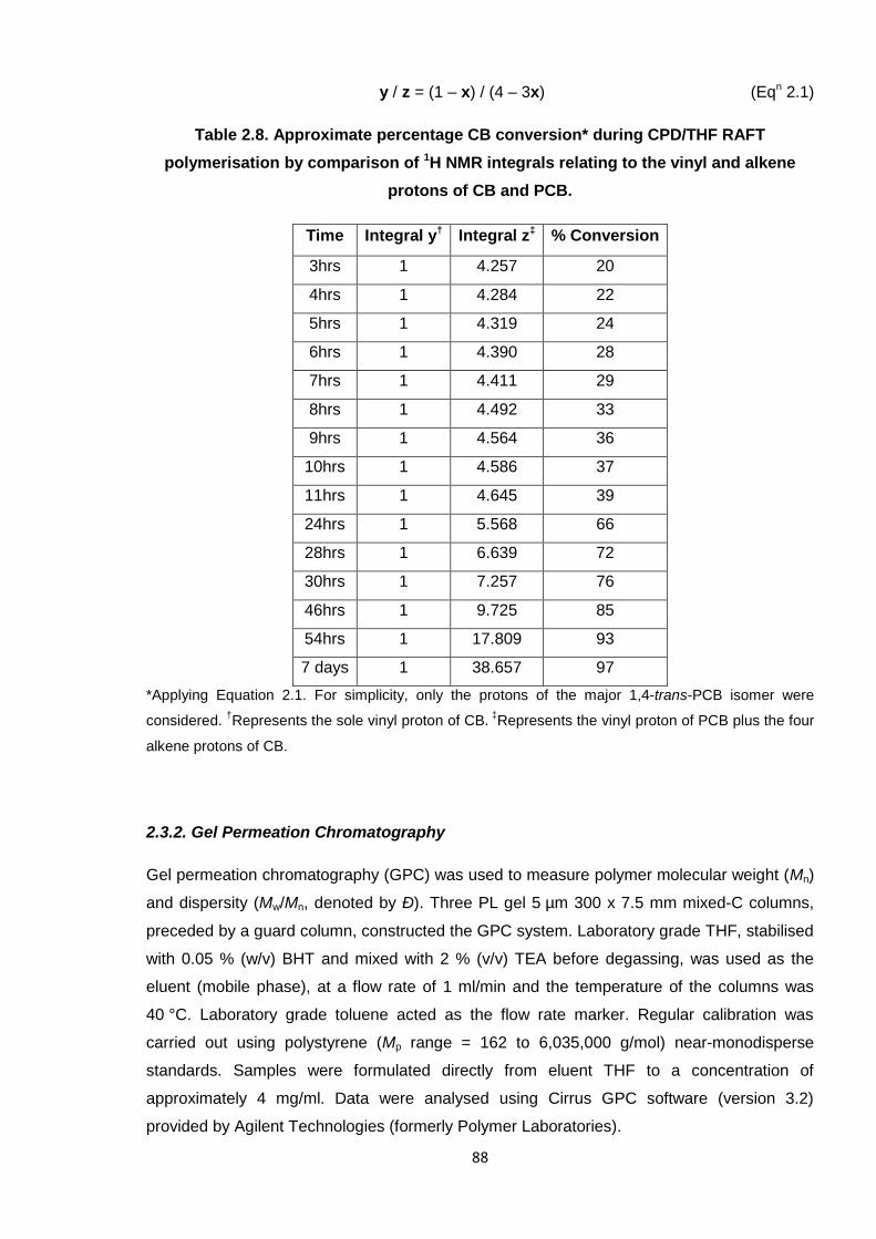
2. Materials and experimental methods
This chapter provides an overview of the materials and experimental methods employed
during the project.
2.1. Materials
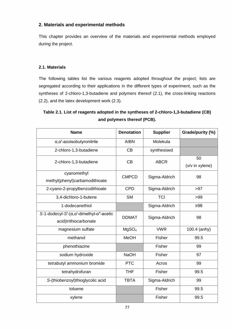
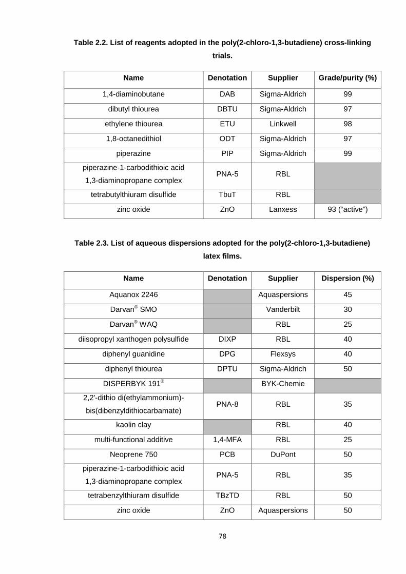
The following tables list the various reagents adopted throughout the project; lists are
segregated according to their applications in the different types of experiment, such as the
syntheses of 2-chloro-1,3-butadiene and polymers thereof (2.1), the cross-linking reactions
(2.2), and the latex development work (2.3).
Table 2.1. List of reagents adopted in the syntheses of 2-chloro-1,3-butadiene (CB)
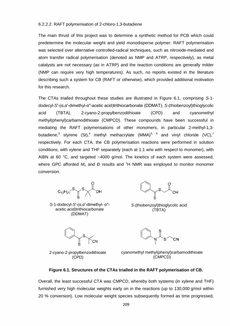
and S-1-dodecyl-S′-(α,α′-dimethyl-α′′-acetic acid)trithiocarbonate, DDMAT] is largely
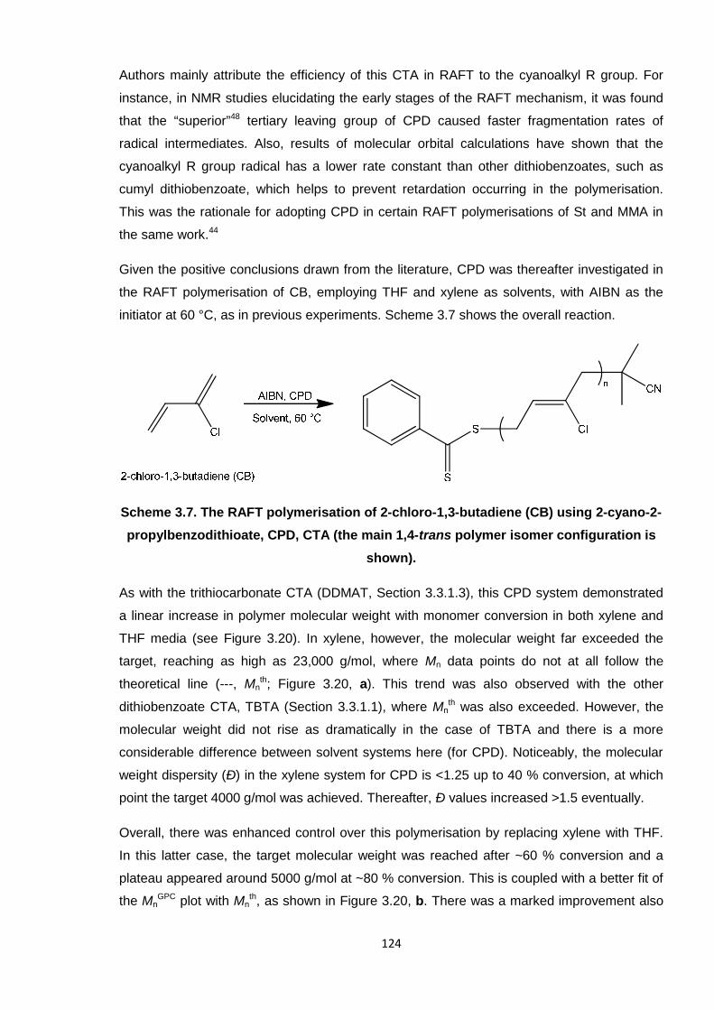
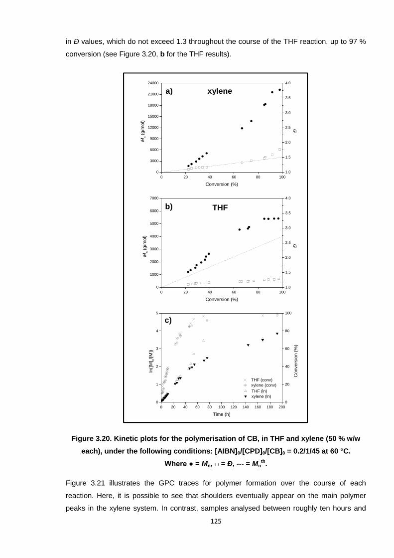
attributed to a “superior”48 leaving group (R = C(Me)2CN). Overall, CPD has shown great
versatility as a CTA for other monomers such as methyl methacrylate (MMA)44, 45 and other
acrylates,34, 46 which are all classified as more-activated monomers (MAMs).26 The DDMAT
CTA, a trithiocarbonate derivative, also performed relatively well for CB (see Section 3.3.1.3),
affording polymer with molecular weights close to Mnth at high conversion. This CTA, being a
trithiocarbonate, is also known to effectively control the polymerisations of MAMs.26 Hence, it
is not a coincidence that these two CTAs are the most suitable (of those tested) for CB; for
137
the first time, it is possible to classify CB as a MAM, within the realm of RAFT chemistry. The
less successful experimental results also support this theory, in that CMPCD (Section
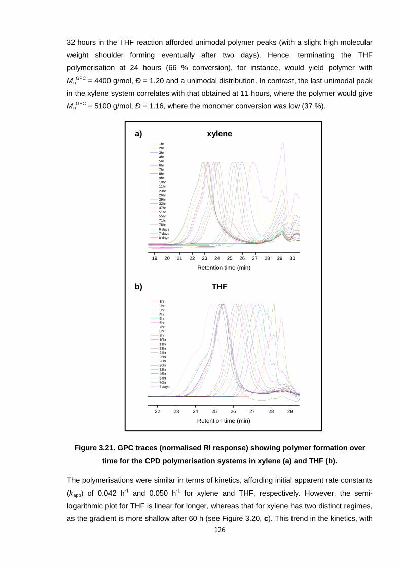
3.3.1.2), a successful CTA for the RAFT polymerisation of vinyl chloride (VC), a less-
activated monomer (LAM),33 did not control the polymerisation in this instance.
It is possible that an alternative initiator, and/or concentration thereof, may be more suitable
in the RAFT polymerisation of CB, although the boiling point of this monomer (62 °C) limits
the reaction temperature. Ideally, a lower temperature system with the same, if not improved,
capabilities would be sought for a more viable application in industry, perhaps to enable the
synthesis of predefined PCB on a larger scale. It is also apparent that solvent has a vital role
in RAFT; throughout these experiments, the THF systems have shown enhanced control
(versus xylene), but these were also slower reactions. Bulk polymerisations (undertaken with
DDMAT and CPD) proceeded more rapidly, but resulted in higher dispersities. It is thought
that the solubility of the CTA45 or initiator57 caused the contrasting results obtained with the
solvent systems investigated herein. Further research into RAFT of CB is necessary,
whereby a broader range of solvents should be tested at varying concentrations. There are
numerous reports of systems employing aromatic solvents, especially combined with the
same CTAs trialled in this work,31, 45, 47 and THF features fairly widely.33, 34 Thus, it would be
interesting to examine the effects of completely different types of solvent, such as DMF or
ACN, which were investigated by Benaglia et al. in the controlled polymerisations of MMA.45
It may be feasible for the optimum CPD system discovered here to be further improved with
a lower concentration of solvent, especially given that reasonable results were obtained for
DDMAT and CPD under bulk conditions. Hence, a concentration (at least of THF) residing
between zero and 50 % (w/w) may afford monodisperse, predefined polymer in an optimum
reaction time.
3.5. References
1. G. Odian, Principles of Polymerization, Wiley Interscience, New York, 1991.2. C. M. Blow and C. Hepburn, eds., Rubber Technology and Manufacture, Butterworths,
London, 1982.3. W. Hofmann, Rubber Technology Handbook, Hanser, Munich, 1996.4. M. Lynch, Chem.-Biol. Interact., 2001, 135-136, 155-167.5. I. E. Muskat and H. E. Northrup, J. Am. Chem. Soc., 1930, 52, 4043-4055.6. US Pat., 4540838, 1985.7. US Pat., 4125564, 1978.8. EP Pat., 0001905, 1978.9. EP Pat., 0114643, 1984.10. M. Orchin, F. Kaplan, R. S. Macomber, R. M. Wilson and H. Zimmer, The Vocabulary of
Organic Chemistry, Wiley, New York, 1980.11. L. M. Mascavage, F. Zhang-Plasket, P. E. Sonnet and D. R. Dalton, Tetrahedron, 2008, 64,
9357-9367.12. W. H. Carothers, I. Williams, A. M. Collins and J. E. Kirby, J. Am. Chem. Soc., 1931, 53, 4203-
4225.
138
13. N. Makhiyanov and A. S. Khachaturov, Polymer Science, Ser. A, 2010, 52, 209 - 219.14. US Pat., 2978501, 1961.15. US Pat., 5523355, 1996.16. K. Itoyama, N. Hirashima, J. Hirano and T. Kadowaki, Polym. J., 1991, 23, 859-864.17. K. Itoyama, N. Shimizu and S. Matsuzawa, Polym. J., 1991, 23, 1139-1142.18. P. J. Flory, Principles of Polymer Chemistry, Cornell University Press, New York, 1953.19. J. M. G. Cowie, Polymers: Chemistry & Physics of Modern Materials, Chapham & Hall, Bath,
1991.20. R. C. Ferguson, J. Polym. Sci., Part A: Gen. Pap., 1964, 2, 4735-4741.21. C. W. Evans, Practical Rubber Compounding and Processing, Applied Science Publishers,
London, 1981.22. G. Odian, in Elastomers and Rubber Elasticity, ACS Symposium Series, 1982, vol. 193, ch. 1,
pp. 1-31.23. T. Yoshida, Mater. Trans., 2003, 44, 2489-2493.24. K. O. Calvert, in Polymer Latices and their Applications, ed. K. O. Calvert, Applied Science
Publishers, London, 1982, pp. 1-10.25. N. Ajellal, C. M. Thomas and J.-F. Carpentier, Polymer, 2008, 49, 4344-4349.26. G. Moad, E. Rizzardo and S. H. Thang, Acc. Chem. Res., 2008, 41, 1133-1142.27. G. Moad, E. Rizzardo and S. H. Thang, Aust. J. Chem., 2005, 58, 379-410.28. G. Moad, E. Rizzardo and S. H. Thang, Aust. J. Chem., 2009, 62, 1402-1472.29. R. P. Babu and R. Dhamodharan, Polym. Int., 2008, 57, 365-371.30. D. S. Germack and K. L. Wooley, J. Polym. Sci., Part A: Polym. Chem., 2007, 45, 4100-4108.31. S. C. Farmer and T. E. Patten, J. Polym. Sci., Part A: Polym. Chem., 2002, 40, 555-563.32. Y. K. Chong, J. Krstina, T. P. T. Le, G. Moad, A. Postma, E. Rizzardo and S. H. Thang,
Macromolecules, 2003, 36, 2256-2272.33. C. M. R. Abreu, P. V. Mendonça, A. C. Serra, J. F. J. Coelho, A. V. Popov, G. Gryn’ova, M. L.
Coote and T. Guliashvili, Macromolecules, 2012, 45, 2200-2208.34. W. Cai, W. Wan, C. Hong, C. Huang and C. Pan, Soft Matter, 2010, 6, 5554-5561.35. S. Kanagasabapathy, A. Sudalai and B. C. Benicewicz, Macromol. Rapid Commun., 2001, 22,
1076-1080.36. D. Benoit, E. Harth, P. Fox, R. M. Waymouth and C. J. Hawker, Macromolecules, 2000, 33,
363-370.37. J. Li, J. El harfi, S. M. Howdle, K. Carmichael and D. J. Irvine, Polym. Chem., 2012, 3, 1495-
1501.38. J. Wootthikanokkhan, M. Peesan and P. Phinyocheep, Eur. Polym. J., 2001, 37, 2063-2071.39. J. T. Lai, D. Filla and R. Shea, Macromolecules, 2002, 35, 6754-6756.40. V. Jitchum and S. Perrier, Macromolecules, 2007, 40, 1408-1412.41. L. Lu, N. Yang and Y. Cai, Chem. Commun., 2005, 5287-5288.42. A. M. Nyström and K. L. Wooley, Tetrahedron, 2008, 64, 8543-8552.43. B. Ebeling and P. Vana, Macromolecules, 2013, 46, 4862-4871.44. Y. K. Chong, J. Krstina, T. P. T. Le, G. Moad, A. Postma, E. Rizzardo and S. H. Thang,
Macromolecules, 2003, 36, 2256-2272.45. M. Benaglia, E. Rizzardo, A. Alberti and M. Guerra, Macromolecules, 2005, 38, 3129-3140.46. E. T. A. van den Dungen, H. Matahwa, J. B. McLeary, R. D. Sanderson and B. Klumperman,
J. Polym. Sci. Part A: Polym. Chem., 2008, 46, 2500-2509.47. C. Weber, T. Neuwirth, K. Kempe, B. Ozkahraman, E. Tamahkar, H. Mert, C. R. Becer and U.
S. Schubert, Macromolecules, 2012, 45, 20-27.48. J. B. McLeary, F. M. Calitz, J. M. McKenzie, M. P. Tonge, R. D. Sanderson and B.
Klumperman, Macromolecules, 2004, 37, 2383-2394.49. B. M. Mandal, Fundamentals of Polymerization, World Scientific, Singapore, 2013.50. WO. Pat., 9801478, 1997.51. S. Perrier and P. Takolpuckdee, J. Polym. Sci. Part A: Polym. Chem., 2005, 43, 5347-5393.52. R. P. Babu and R. Dhamodharan, Polym. Int., 2008, 57, 365-371.53. M. R. Wood, D. J. Duncalf, P. Findlay, S. P. Rannard and S. Perrier, Aust. J. Chem., 2007, 60,
772-778.54. G. Gody, T. Maschmeyer, P. B. Zetterlund and S. Perrier, Nat. Commun., 2013, Article
Number 2505.55. N. Pullan, M. Liu and P. D. Topham, Polym. Chem., 2013, 4, 2272-2277.56. D. J. Keddie, G. Moad, E. Rizzardo and S. H. Thang, Macromolecules, 2012, 45, 5321-5342.57. C. J. Dürr, S. G. J. Emmerling, A. Kaiser, S. Brandau, A. K. T. Habicht, M. Klimpel and C.
Barner-Kowollik, J. Polym. Sci. Part A: Polym. Chem., 2012, 50, 174-180.
139
CHAPTER 4
SPECTROSCOPIC ANALYSIS OF THE
CROSS-LINKING OF
POLY(2-CHLORO-1,3-BUTADIENE)
140
4. Spectroscopic analysis of the cross-linking of poly(2-chloro-1,3-butadiene)
This chapter details the first of two industrially-driven studies concerning poly(2-chloro-1,3-
butadiene) (PCB) which were each, in part, undertaken in collaboration with Robinson
Brothers Ltd. (RBL), West Bromwich. Spectroscopic investigations into elucidating the cross-
linking mechanism of PCB are discussed herein, whereby the subsequent chapter focusses
on the latex development of this polymer (Chapter 5).
4.1. Cross-linking poly(2-chloro-1,3-butadiene)
The quest to elucidate the cross-linking mechanism of PCB was rationalised in the
Introduction to this thesis (Section 1.2.2). Briefly, ethylene thiourea (ETU) is the industrial
standard reagent for cross-linking PCB, affording optimal physical properties in the rubber
product. However, concerns over the toxicity of this reagent have emerged within the
European Union so that the applications of ETU, on the whole, will eventually be severely
restricted if not completely banished. It is industrially relevant, therefore, to study the cross-
linking reaction between PCB and ETU so that a replacement can be sought. Herein, a
discussion into the cross-linking of PCB is provided, with the objective to elucidate the ETU
mechanism, which is as yet unconfirmed in the literature.
These particular studies employed ~3000 g/mol PCB, which had been synthesised via
uncontrolled free radical polymerisation (as detailed in Section 3.2). The original drive of the
RAFT polymerisation studies (Section 3.3) was to furnish PCB especially for this purpose,
however this was not feasible as the cross-linking experiments had to take place immediately
at the start of the project so as to generate data readily for RBL. In general, these
experiments were performed in test tubes or glass vials, the reagents mixed with polymer,
and the resultant solutions heated at 160 °C to simulate cross-linking. Aliquots were taken
periodically for the relevant analyses.
K. Berry (RBL) examined the cross-linking of PCB rubber with a similar variety of reagents in
parallel to these particular investigations.1 In stark contrast to the rubber (Mn ~500,000 g/mol
from GPC analysis against PSt standards), the PCB synthesised in-house was more
practical and easier to analyse by standard solution-based techniques, due to enhanced
solubility. The rubber is more complicated to process, as it requires milling so as to
incorporate the reagents and high pressure for the cross-linking reactions (employing a
rheometer). Once fully cross-linked, the rubber is rendered totally insoluble, so that only
physical tests can be conducted on the final product (such as tensile testing and rheology).
Thus, oligomeric PCB was considered because the material would make the process more
straightforward, overall. Also, a pseudo-infinite three-dimensional network would not be
141
created within the oligomers due to its considerably lower molecular weight and shorter chain
lengths. It was therefore intended to utilise a range of different analytical techniques, such as
FTIR, GPC and NMR, to monitor the reactions throughout. However, the NMR and GPC
results failed to offer any additional information to that provided by FTIR, so the focus
remained solely on the latter. Where necessary, the results from the rubber investigations of
Berry1 are presented to complement the observations here.
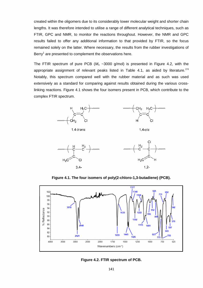
The FTIR spectrum of pure PCB (Mn ~3000 g/mol) is presented in Figure 4.2, with the
appropriate assignment of relevant peaks listed in Table 4.1, as aided by literature.2-5
Notably, this spectrum compared well with the rubber material and as such was used
extensively as a standard for comparing against results obtained during the various cross-
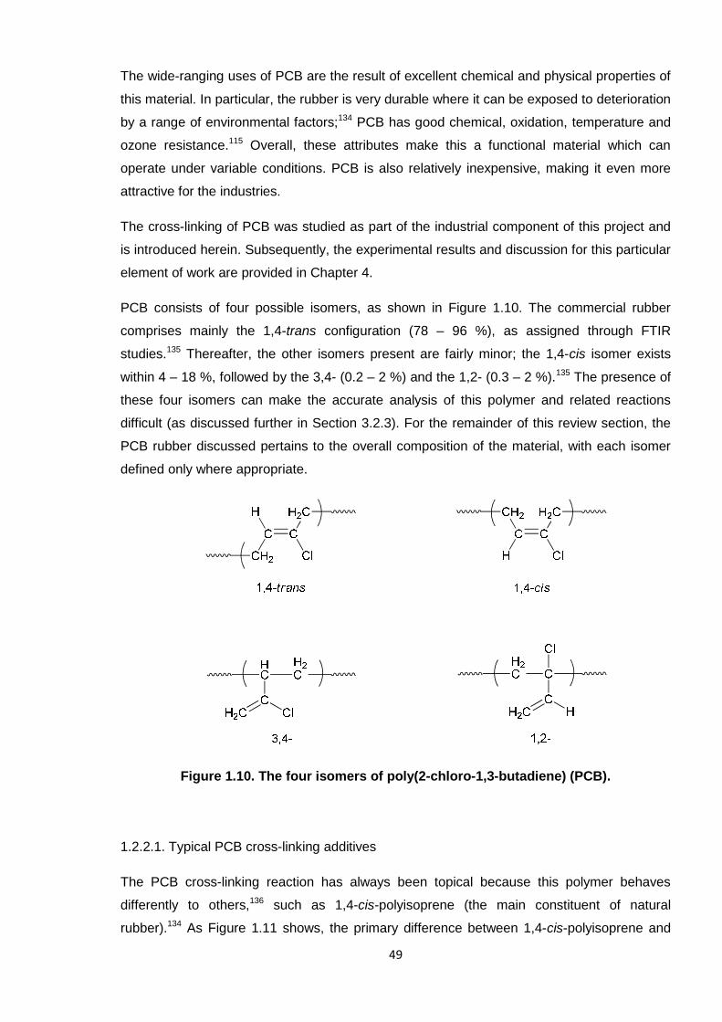
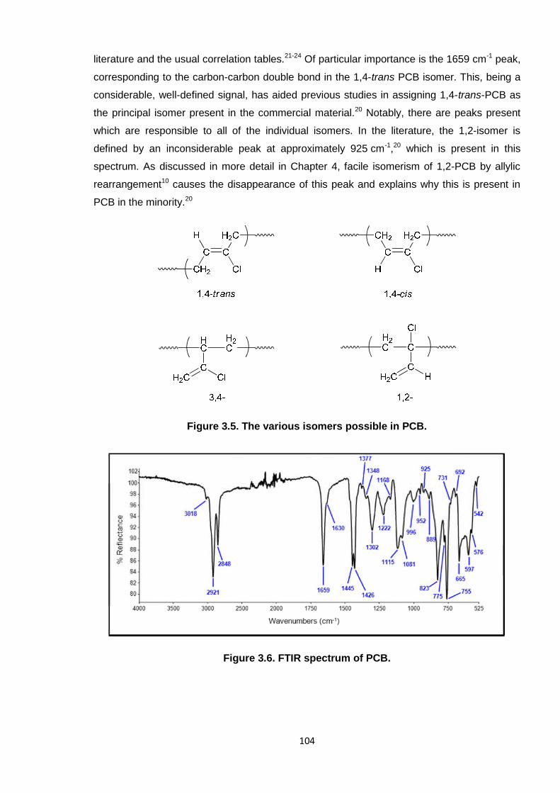
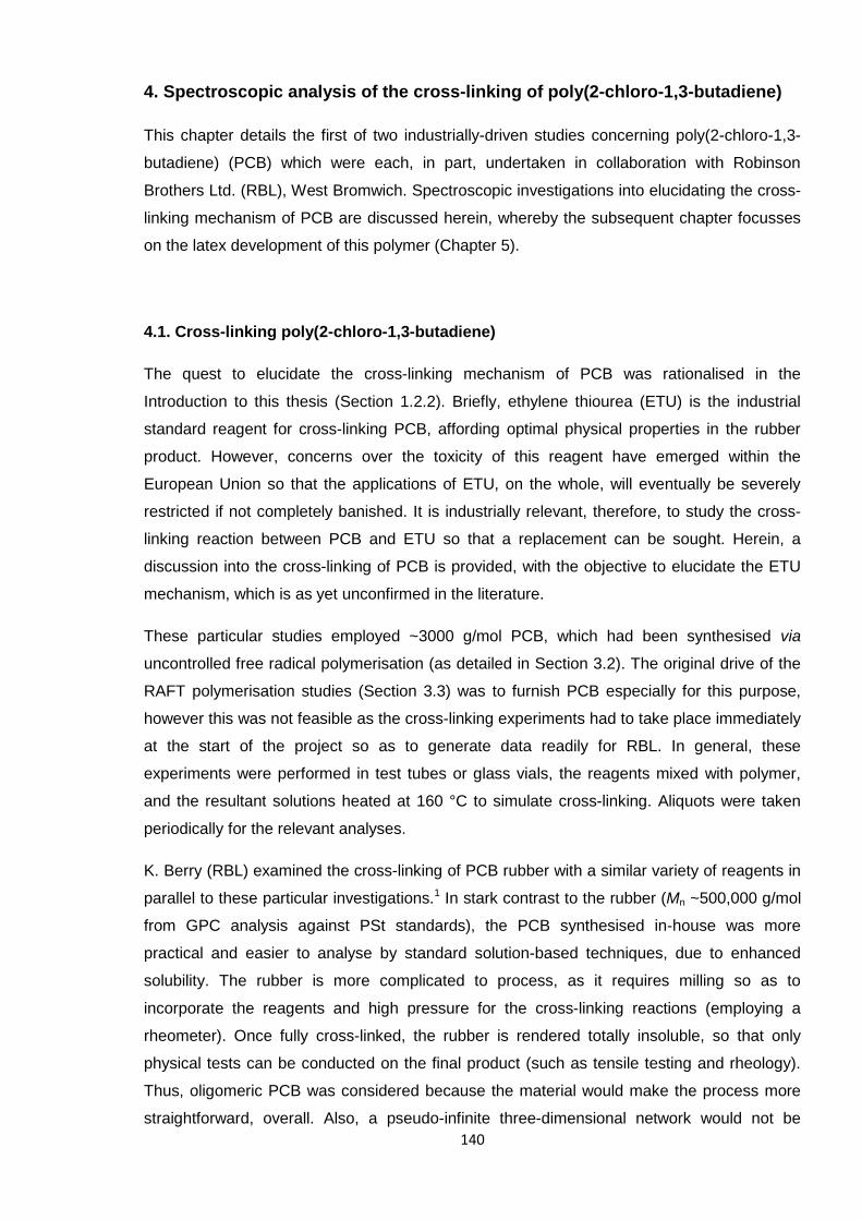
linking reactions. Figure 4.1 shows the four isomers present in PCB, which contribute to the
complex FTIR spectrum.
Figure 4.1. The four isomers of poly(2-chloro-1,3-butadiene) (PCB).
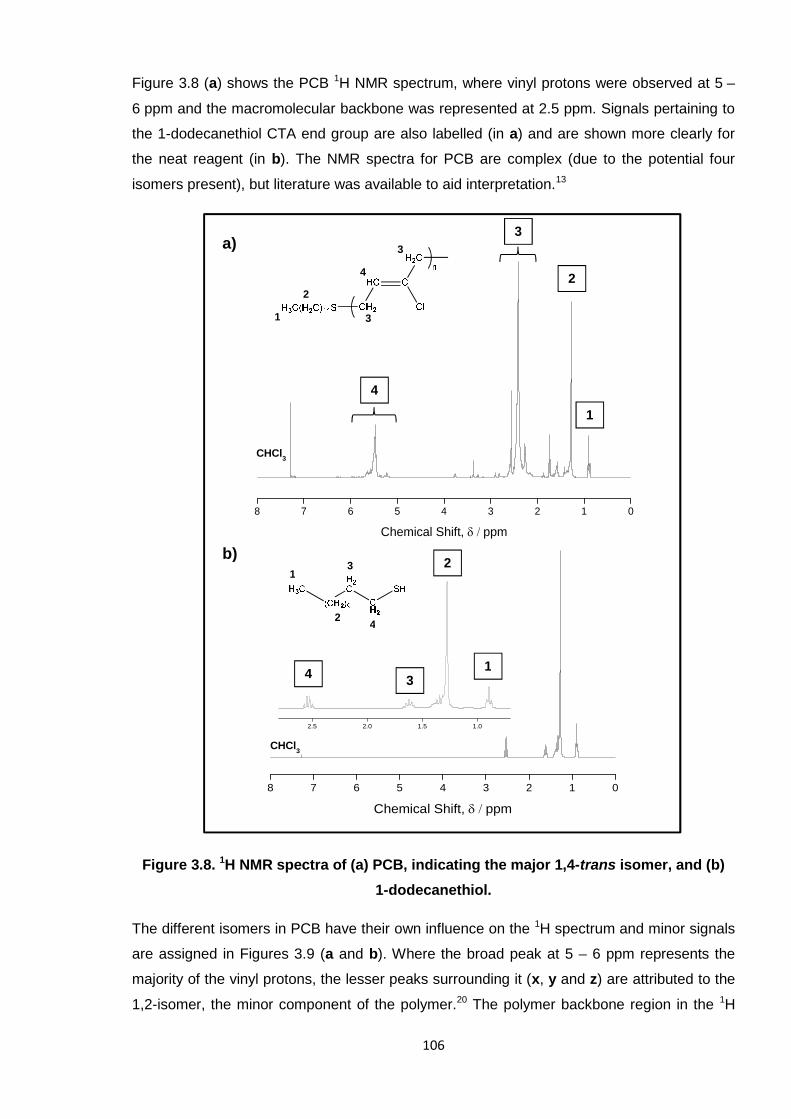
Figure 4.2. FTIR spectrum of PCB.
142
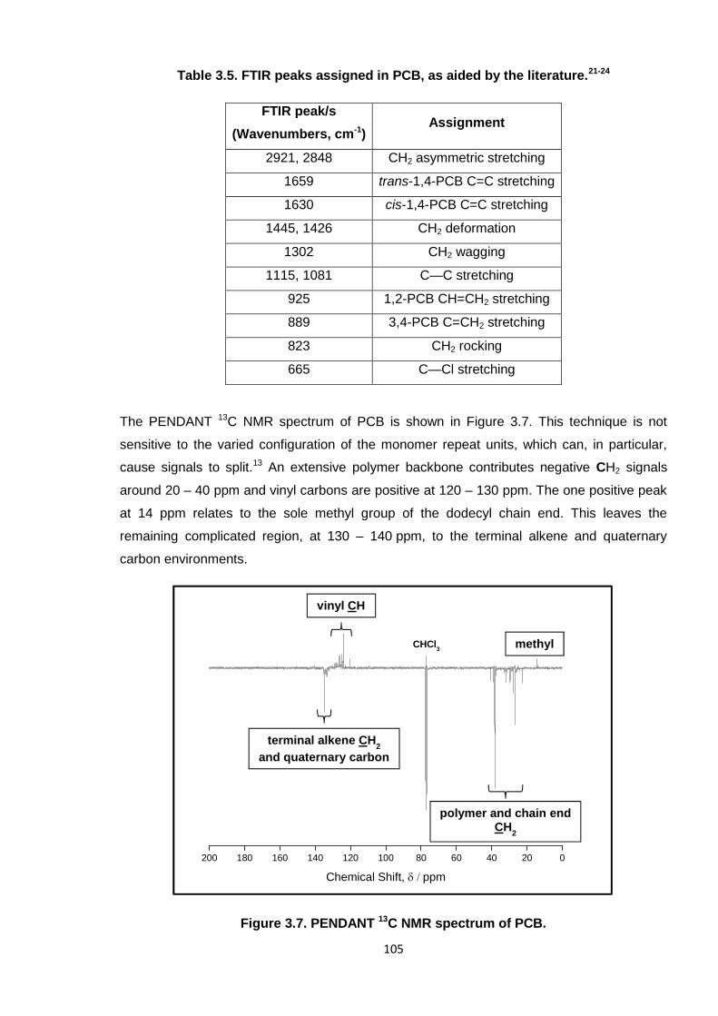
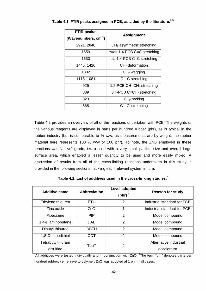
Table 4.1. FTIR peaks assigned in PCB, as aided by the literature.2-5
FTIR peak/s
(Wavenumbers, cm-1)Assignment
2921, 2848 CH2 asymmetric stretching
1659 trans-1,4-PCB C=C stretching
1630 cis-1,4-PCB C=C stretching
1445, 1426 CH2 deformation
1302 CH2 wagging
1115, 1081 C—C stretching
925 1,2-PCB CH=CH2 stretching
889 3,4-PCB C=CH2 stretching
823 CH2 rocking
665 C—Cl stretching
Table 4.2 provides an overview of all of the reactions undertaken with PCB. The weights of
the various reagents are displayed in parts per hundred rubber (phr), as is typical in the
rubber industry (but is comparable to % w/w, as measurements are by weight; the rubber
material here represents 100 % w/w or 100 phr). To note, the ZnO employed in these
reactions was “active” grade, i.e. a solid with a very small particle size and overall large
surface area, which enabled a lesser quantity to be used and more easily mixed. A
discussion of results from all of the cross-linking reactions undertaken in this study is
provided in the following sections, tackling each relevant system in turn.
Table 4.2. List of additives used in the cross-linking studies.*
Additive name AbbreviationLevel adopted
(phr) †Reason for study
Ethylene thiourea ETU 2 Industrial standard for PCB
Zinc oxide ZnO 1 Industrial standard for PCB
Piperazine PIP 2 Model compound
1,4-Diaminobutane DAB 2 Model compound
Dibutyl thiourea DBTU 2 Model compound
1,8-Octanedithiol ODT 2 Model compound
Tetrabutylthiuram
disulfideTbuT 2
Alternative industrial
accelerator*All additives were tested individually and in conjunction with ZnO.
†The term “phr” denotes parts per
hundred rubber, i.e. relative to polymer; ZnO was adopted at 1 phr in all cases.
143
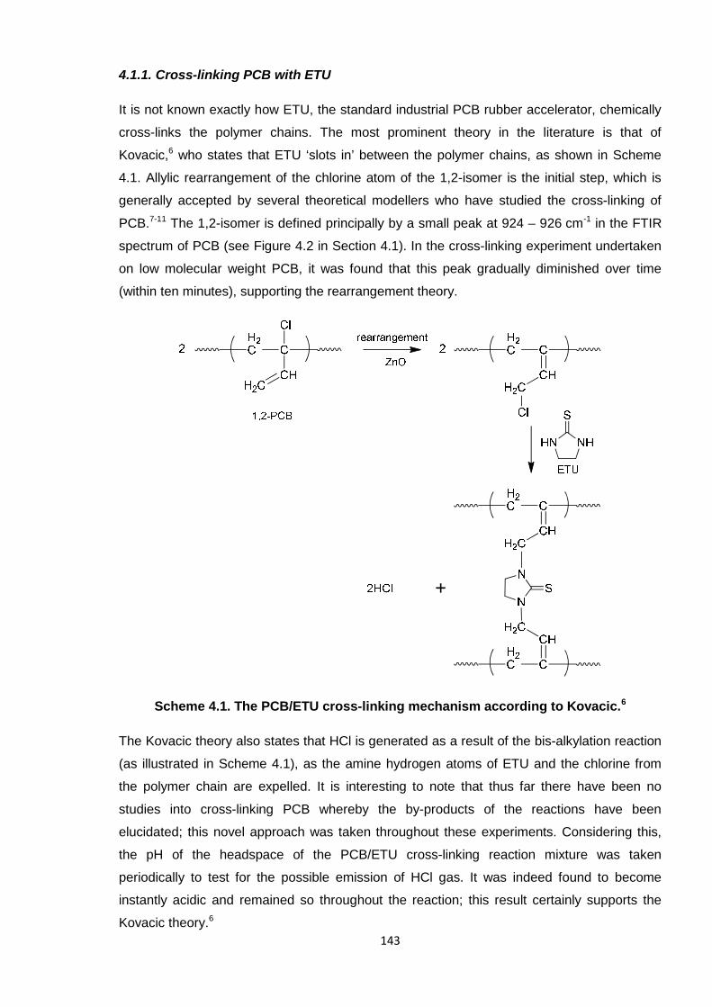
4.1.1. Cross-linking PCB with ETU
It is not known exactly how ETU, the standard industrial PCB rubber accelerator, chemically
cross-links the polymer chains. The most prominent theory in the literature is that of
Kovacic,6 who states that ETU ‘slots in’ between the polymer chains, as shown in Scheme
4.1. Allylic rearrangement of the chlorine atom of the 1,2-isomer is the initial step, which is
generally accepted by several theoretical modellers who have studied the cross-linking of
PCB.7-11 The 1,2-isomer is defined principally by a small peak at 924 – 926 cm-1 in the FTIR
spectrum of PCB (see Figure 4.2 in Section 4.1). In the cross-linking experiment undertaken
on low molecular weight PCB, it was found that this peak gradually diminished over time
(within ten minutes), supporting the rearrangement theory.
Scheme 4.1. The PCB/ETU cross-linking mechanism according to Kovacic.6
The Kovacic theory also states that HCl is generated as a result of the bis-alkylation reaction
(as illustrated in Scheme 4.1), as the amine hydrogen atoms of ETU and the chlorine from
the polymer chain are expelled. It is interesting to note that thus far there have been no
studies into cross-linking PCB whereby the by-products of the reactions have been
elucidated; this novel approach was taken throughout these experiments. Considering this,
the pH of the headspace of the PCB/ETU cross-linking reaction mixture was taken
periodically to test for the possible emission of HCl gas. It was indeed found to become
instantly acidic and remained so throughout the reaction; this result certainly supports the
Kovacic theory.6
144
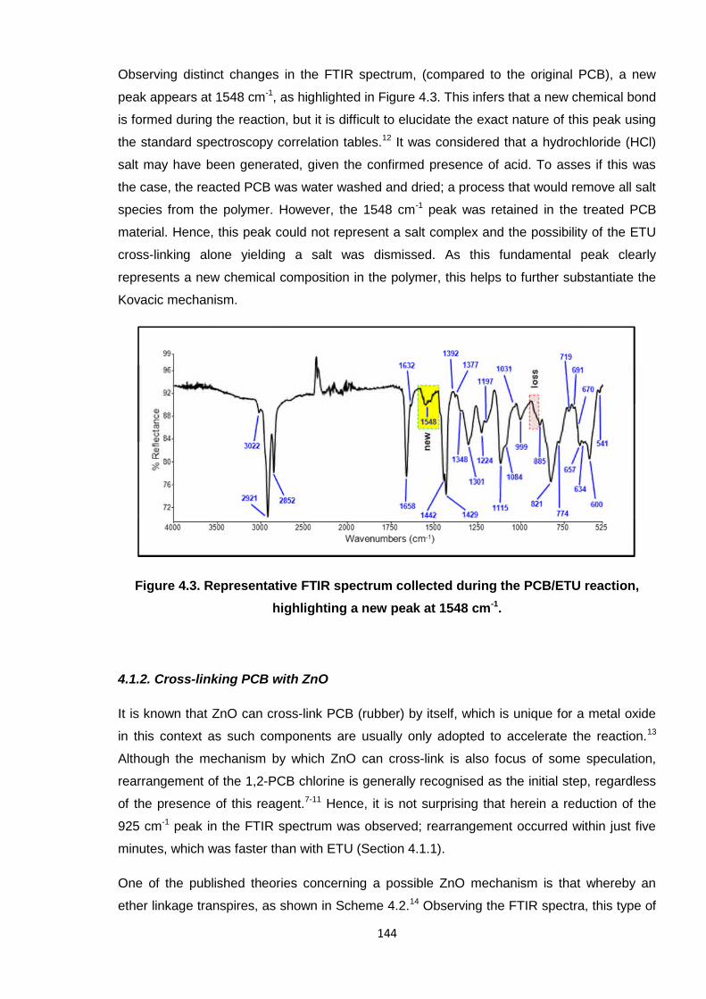
Observing distinct changes in the FTIR spectrum, (compared to the original PCB), a new
peak appears at 1548 cm-1, as highlighted in Figure 4.3. This infers that a new chemical bond
is formed during the reaction, but it is difficult to elucidate the exact nature of this peak using
the standard spectroscopy correlation tables.12 It was considered that a hydrochloride (HCl)
salt may have been generated, given the confirmed presence of acid. To asses if this was
the case, the reacted PCB was water washed and dried; a process that would remove all salt
species from the polymer. However, the 1548 cm-1 peak was retained in the treated PCB
material. Hence, this peak could not represent a salt complex and the possibility of the ETU
cross-linking alone yielding a salt was dismissed. As this fundamental peak clearly
represents a new chemical composition in the polymer, this helps to further substantiate the
Kovacic mechanism.
Figure 4.3. Representative FTIR spectrum collected during the PCB/ETU reaction,
highlighting a new peak at 1548 cm-1.
4.1.2. Cross-linking PCB with ZnO
It is known that ZnO can cross-link PCB (rubber) by itself, which is unique for a metal oxide
in this context as such components are usually only adopted to accelerate the reaction.13
Although the mechanism by which ZnO can cross-link is also focus of some speculation,
rearrangement of the 1,2-PCB chlorine is generally recognised as the initial step, regardless
of the presence of this reagent.7-11 Hence, it is not surprising that herein a reduction of the
925 cm-1 peak in the FTIR spectrum was observed; rearrangement occurred within just five
minutes, which was faster than with ETU (Section 4.1.1).
One of the published theories concerning a possible ZnO mechanism is that whereby an
ether linkage transpires, as shown in Scheme 4.2.14 Observing the FTIR spectra, this type of
145
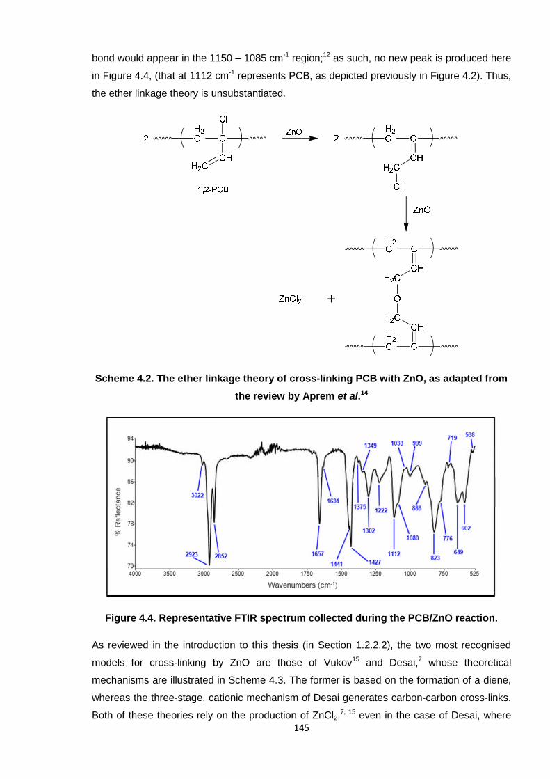
bond would appear in the 1150 – 1085 cm-1 region;12 as such, no new peak is produced here
in Figure 4.4, (that at 1112 cm-1 represents PCB, as depicted previously in Figure 4.2). Thus,
the ether linkage theory is unsubstantiated.
Scheme 4.2. The ether linkage theory of cross-linking PCB with ZnO, as adapted from
the review by Aprem et al.14
Figure 4.4. Representative FTIR spectrum collected during the PCB/ZnO reaction.
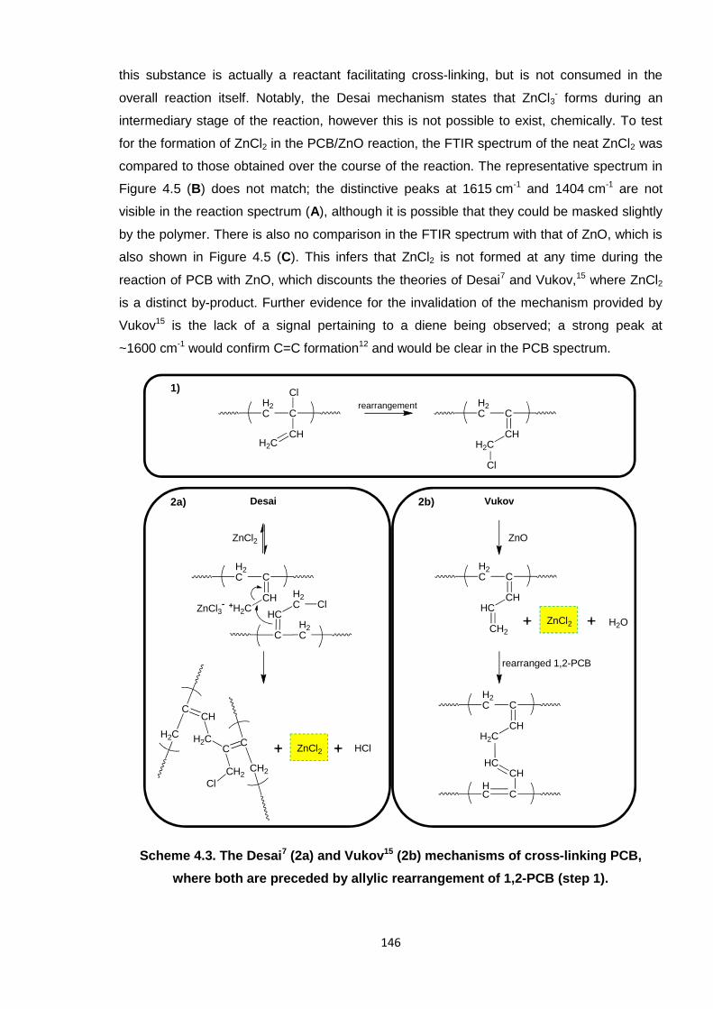
As reviewed in the introduction to this thesis (in Section 1.2.2.2), the two most recognised
models for cross-linking by ZnO are those of Vukov15 and Desai,7 whose theoretical
mechanisms are illustrated in Scheme 4.3. The former is based on the formation of a diene,
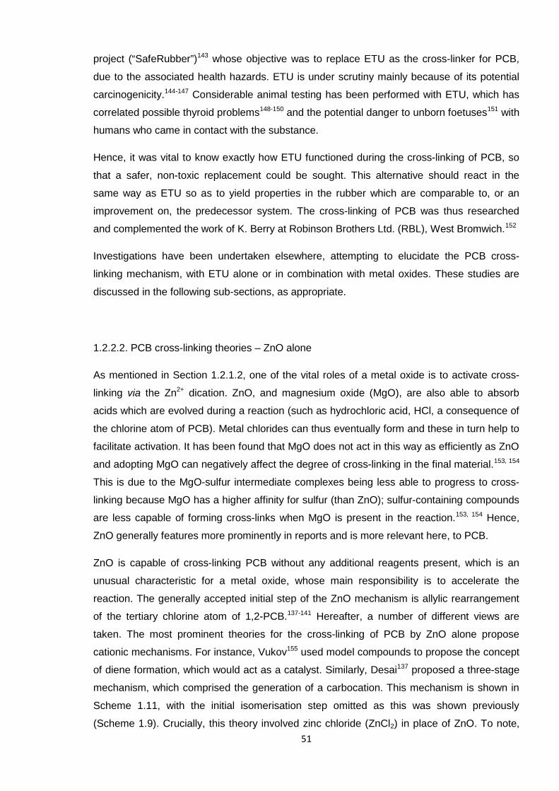
whereas the three-stage, cationic mechanism of Desai generates carbon-carbon cross-links.
Both of these theories rely on the production of ZnCl2,7, 15 even in the case of Desai, where
146
this substance is actually a reactant facilitating cross-linking, but is not consumed in the
overall reaction itself. Notably, the Desai mechanism states that ZnCl3- forms during an
intermediary stage of the reaction, however this is not possible to exist, chemically. To test
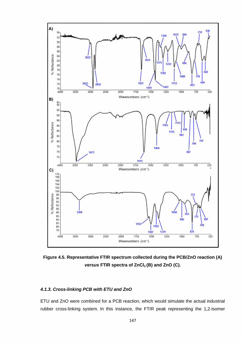
for the formation of ZnCl2 in the PCB/ZnO reaction, the FTIR spectrum of the neat ZnCl2 was
compared to those obtained over the course of the reaction. The representative spectrum in
Figure 4.5 (B) does not match; the distinctive peaks at 1615 cm-1 and 1404 cm-1 are not
visible in the reaction spectrum (A), although it is possible that they could be masked slightly
by the polymer. There is also no comparison in the FTIR spectrum with that of ZnO, which is
also shown in Figure 4.5 (C). This infers that ZnCl2 is not formed at any time during the
reaction of PCB with ZnO, which discounts the theories of Desai7 and Vukov,15 where ZnCl2
is a distinct by-product. Further evidence for the invalidation of the mechanism provided by
Vukov15 is the lack of a signal pertaining to a diene being observed; a strong peak at
~1600 cm-1 would confirm C=C formation12 and would be clear in the PCB spectrum.
Scheme 4.3. The Desai7 (2a) and Vukov15 (2b) mechanisms of cross-linking PCB,
where both are preceded by allylic rearrangement of 1,2-PCB (step 1).
ZnCl2
H2C C
CH+H2CZnCl3
-
H2CC
HC
H2C Cl
H2C
CCH
H2C
CH2
CC
CH2
Cl
ZnCl2 HCl
H2C C
CHH2C
ClH2C C
CHH2C
Cl
rearrangement
ZnO
H2C C
CHHC
CH2
ZnCl2 H2O
rearranged 1,2-PCB
H2C C
CHH2C
HC C
CHHC
Desai Vukov
1)
2a) 2b)
147
Figure 4.5. Representative FTIR spectrum collected during the PCB/ZnO reaction (A)
versus FTIR spectra of ZnCl2 (B) and ZnO (C).
4.1.3. Cross-linking PCB with ETU and ZnO
ETU and ZnO were combined for a PCB reaction, which would simulate the actual industrial
rubber cross-linking system. In this instance, the FTIR peak representing the 1,2-isomer
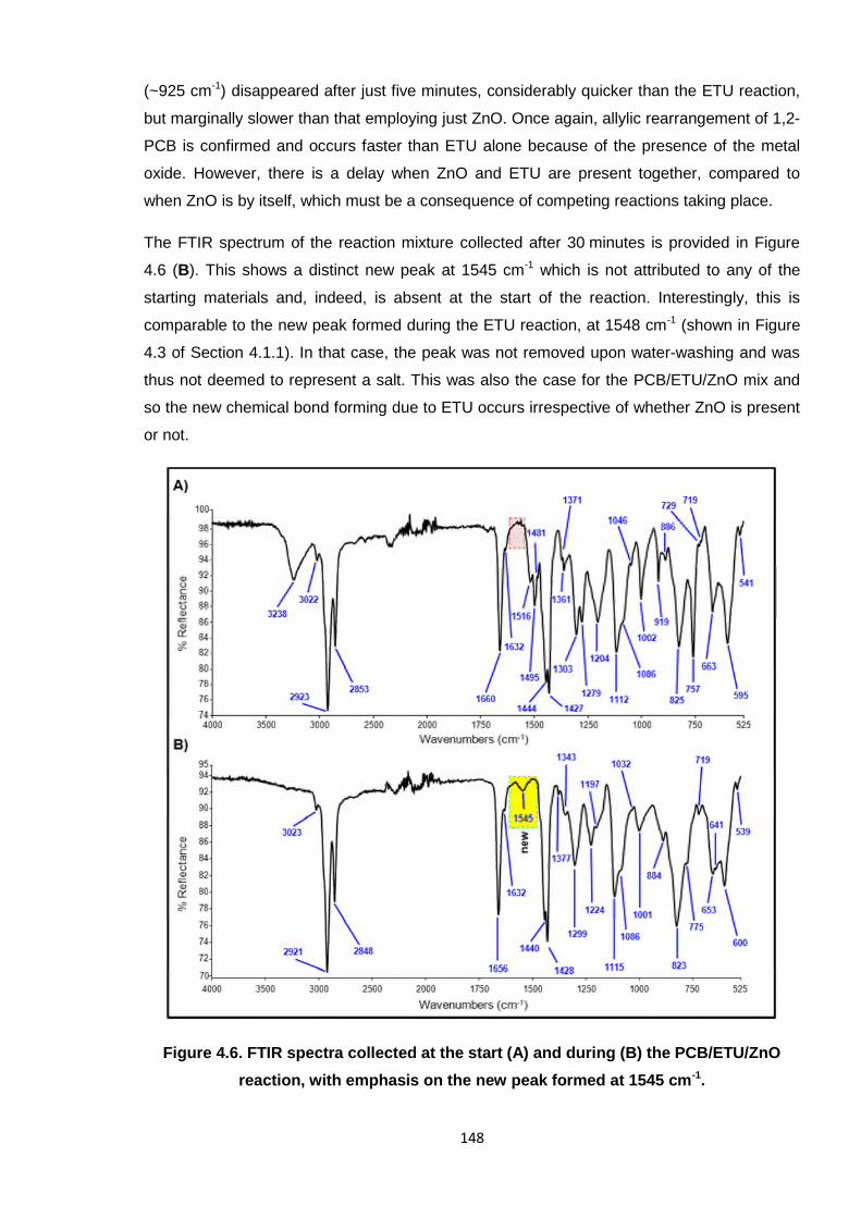
148
(~925 cm-1) disappeared after just five minutes, considerably quicker than the ETU reaction,
but marginally slower than that employing just ZnO. Once again, allylic rearrangement of 1,2-
PCB is confirmed and occurs faster than ETU alone because of the presence of the metal
oxide. However, there is a delay when ZnO and ETU are present together, compared to
when ZnO is by itself, which must be a consequence of competing reactions taking place.
The FTIR spectrum of the reaction mixture collected after 30 minutes is provided in Figure
4.6 (B). This shows a distinct new peak at 1545 cm-1 which is not attributed to any of the
starting materials and, indeed, is absent at the start of the reaction. Interestingly, this is
comparable to the new peak formed during the ETU reaction, at 1548 cm-1 (shown in Figure
4.3 of Section 4.1.1). In that case, the peak was not removed upon water-washing and was
thus not deemed to represent a salt. This was also the case for the PCB/ETU/ZnO mix and
so the new chemical bond forming due to ETU occurs irrespective of whether ZnO is present
or not.
Figure 4.6. FTIR spectra collected at the start (A) and during (B) the PCB/ETU/ZnO
reaction, with emphasis on the new peak formed at 1545 cm-1.
149
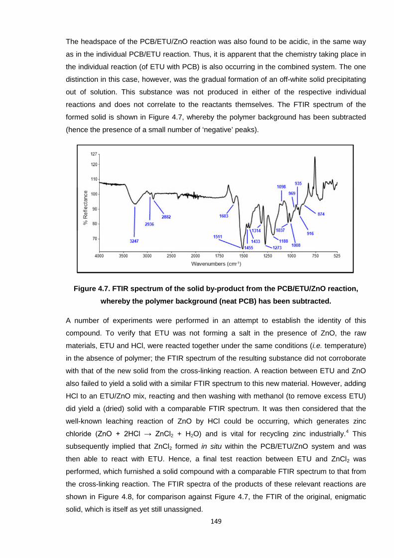
The headspace of the PCB/ETU/ZnO reaction was also found to be acidic, in the same way
as in the individual PCB/ETU reaction. Thus, it is apparent that the chemistry taking place in
the individual reaction (of ETU with PCB) is also occurring in the combined system. The one
distinction in this case, however, was the gradual formation of an off-white solid precipitating
out of solution. This substance was not produced in either of the respective individual
reactions and does not correlate to the reactants themselves. The FTIR spectrum of the
formed solid is shown in Figure 4.7, whereby the polymer background has been subtracted
(hence the presence of a small number of ‘negative’ peaks).
Figure 4.7. FTIR spectrum of the solid by-product from the PCB/ETU/ZnO reaction,
whereby the polymer background (neat PCB) has been subtracted.
A number of experiments were performed in an attempt to establish the identity of this
compound. To verify that ETU was not forming a salt in the presence of ZnO, the raw
materials, ETU and HCl, were reacted together under the same conditions (i.e. temperature)
in the absence of polymer; the FTIR spectrum of the resulting substance did not corroborate
with that of the new solid from the cross-linking reaction. A reaction between ETU and ZnO
also failed to yield a solid with a similar FTIR spectrum to this new material. However, adding
HCl to an ETU/ZnO mix, reacting and then washing with methanol (to remove excess ETU)
did yield a (dried) solid with a comparable FTIR spectrum. It was then considered that the
well-known leaching reaction of ZnO by HCl could be occurring, which generates zinc
chloride (ZnO + 2HCl → ZnCl2 + H2O) and is vital for recycling zinc industrially.4 This
subsequently implied that ZnCl2 formed in situ within the PCB/ETU/ZnO system and was
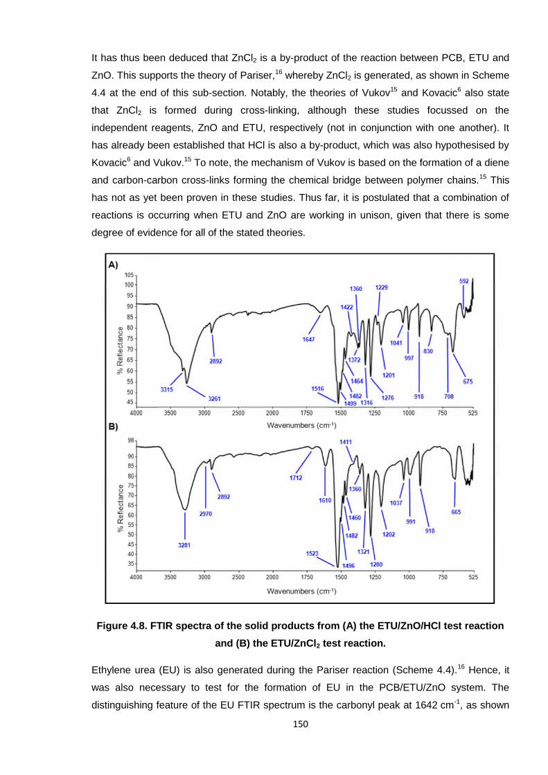
then able to react with ETU. Hence, a final test reaction between ETU and ZnCl2 was
performed, which furnished a solid compound with a comparable FTIR spectrum to that from
the cross-linking reaction. The FTIR spectra of the products of these relevant reactions are
shown in Figure 4.8, for comparison against Figure 4.7, the FTIR of the original, enigmatic
solid, which is itself as yet still unassigned.
150
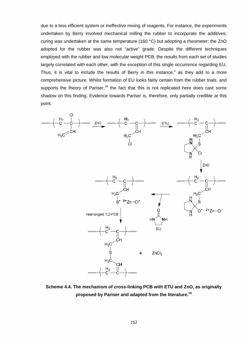
It has thus been deduced that ZnCl2 is a by-product of the reaction between PCB, ETU and
ZnO. This supports the theory of Pariser,16 whereby ZnCl2 is generated, as shown in Scheme
4.4 at the end of this sub-section. Notably, the theories of Vukov15 and Kovacic6 also state
that ZnCl2 is formed during cross-linking, although these studies focussed on the
independent reagents, ZnO and ETU, respectively (not in conjunction with one another). It
has already been established that HCl is also a by-product, which was also hypothesised by
Kovacic6 and Vukov.15 To note, the mechanism of Vukov is based on the formation of a diene
and carbon-carbon cross-links forming the chemical bridge between polymer chains.15 This
has not as yet been proven in these studies. Thus far, it is postulated that a combination of
reactions is occurring when ETU and ZnO are working in unison, given that there is some
degree of evidence for all of the stated theories.
Figure 4.8. FTIR spectra of the solid products from (A) the ETU/ZnO/HCl test reaction
and (B) the ETU/ZnCl2 test reaction.
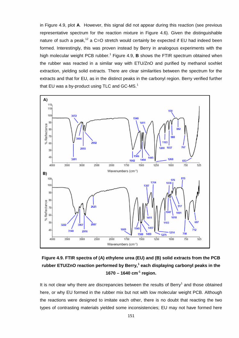
Ethylene urea (EU) is also generated during the Pariser reaction (Scheme 4.4).16 Hence, it
was also necessary to test for the formation of EU in the PCB/ETU/ZnO system. The
distinguishing feature of the EU FTIR spectrum is the carbonyl peak at 1642 cm-1, as shown
151
in Figure 4.9, plot A. However, this signal did not appear during this reaction (see previous
representative spectrum for the reaction mixture in Figure 4.6). Given the distinguishable
nature of such a peak,12 a C=O stretch would certainly be expected if EU had indeed been
formed. Interestingly, this was proven instead by Berry in analogous experiments with the
high molecular weight PCB rubber.1 Figure 4.9, B shows the FTIR spectrum obtained when
the rubber was reacted in a similar way with ETU/ZnO and purified by methanol soxhlet
extraction, yielding solid extracts. There are clear similarities between the spectrum for the
extracts and that for EU, as in the distinct peaks in the carbonyl region. Berry verified further
that EU was a by-product using TLC and GC-MS.1
Figure 4.9. FTIR spectra of (A) ethylene urea (EU) and (B) solid extracts from the PCB
rubber ETU/ZnO reaction performed by Berry,1 each displaying carbonyl peaks in the
1670 – 1640 cm-1 region.
It is not clear why there are discrepancies between the results of Berry1 and those obtained
here, or why EU formed in the rubber mix but not with low molecular weight PCB. Although
the reactions were designed to imitate each other, there is no doubt that reacting the two
types of contrasting materials yielded some inconsistencies; EU may not have formed here
152
due to a less efficient system or ineffective mixing of reagents. For instance, the experiments
undertaken by Berry involved mechanical milling the rubber to incorporate the additives;
curing was undertaken at the same temperature (160 °C) but adopting a rheometer; the ZnO
adopted for the rubber was also not “active” grade. Despite the different techniques
employed with the rubber and low molecular weight PCB, the results from each set of studies
largely correlated with each other, with the exception of this single occurrence regarding EU.
Thus, it is vital to include the results of Berry in this instance,1 as they add to a more
comprehensive picture. Whilst formation of EU looks fairly certain from the rubber trials, and
supports the theory of Pariser,16 the fact that this is not replicated here does cast some
shadow on this finding. Evidence towards Pariser is, therefore, only partially credible at this
point.
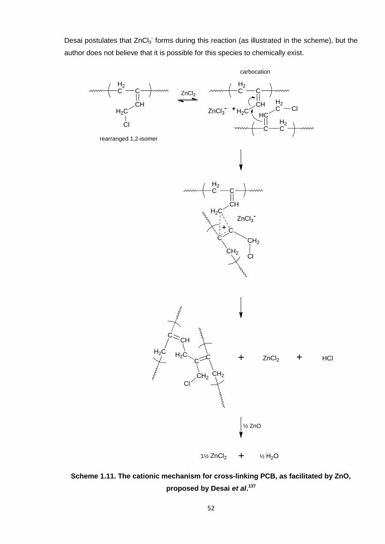
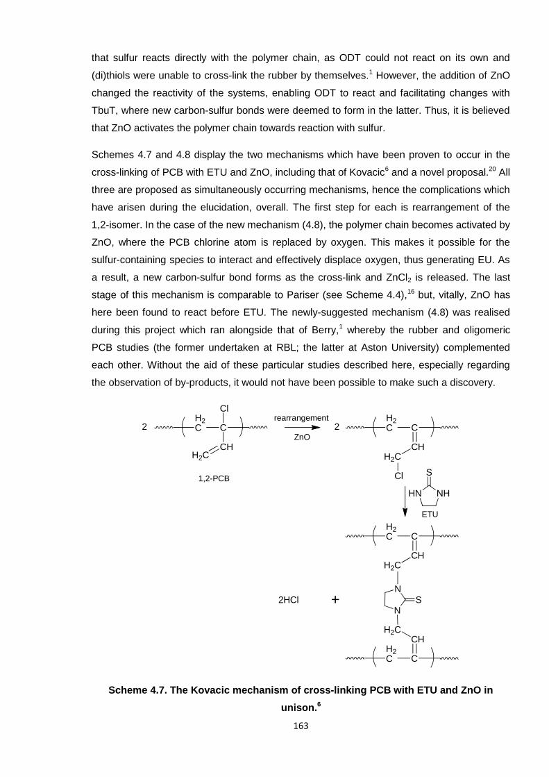
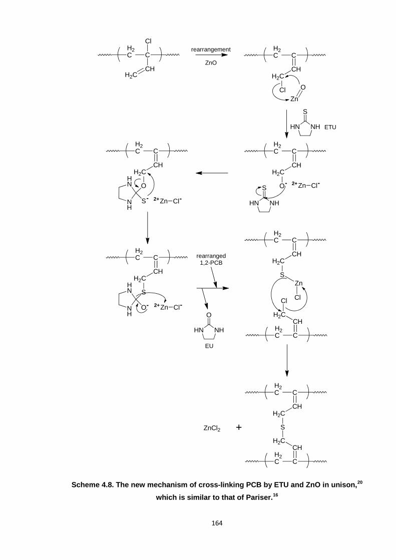
Scheme 4.4. The mechanism of cross-linking PCB with ETU and ZnO, as originally
proposed by Pariser and adapted from the literature.16
153
4.1.4. Cross-linking PCB with model compounds and other standard accelerators
In order to yield further information as to the nature of the ETU reaction, several model
compounds and a further standard rubber accelerator were employed in analogous
reactions. These compounds are illustrated in Table 4.3 and all exhibit some chemical
functionality that can be compared with ETU. The tests were principally conducted to
examine the roles of certain relevant functionalities, such as thiols (i.e. the sulfur atom) and
amines.
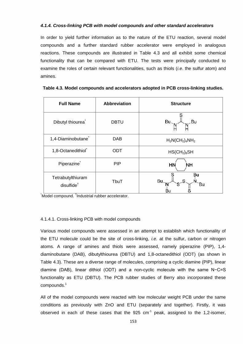
Table 4.3. Model compounds and accelerators adopted in PCB cross-linking studies.
Full Name Abbreviation Structure
Dibutyl thiourea* DBTU
1,4-Diaminobutane* DAB H2N(CH2)4NH2
1,8-Octanedithiol* ODT HS(CH2)8SH
Piperazine* PIP
Tetrabutylthiuram
disulfide†TbuT
*Model compound.
†Industrial rubber accelerator.
4.1.4.1. Cross-linking PCB with model compounds
Various model compounds were assessed in an attempt to establish which functionality of
the ETU molecule could be the site of cross-linking, i.e. at the sulfur, carbon or nitrogen
atoms. A range of amines and thiols were assessed, namely piperazine (PIP), 1,4-
diaminobutane (DAB), dibutylthiourea (DBTU) and 1,8-octanedithiol (ODT) (as shown in
Table 4.3). These are a diverse range of molecules, comprising a cyclic diamine (PIP), linear
diamine (DAB), linear dithiol (ODT) and a non-cyclic molecule with the same N−C=S
functionality as ETU (DBTU). The PCB rubber studies of Berry also incorporated these
compounds.1
All of the model compounds were reacted with low molecular weight PCB under the same
conditions as previously with ZnO and ETU (separately and together). Firstly, it was
observed in each of these cases that the 925 cm-1 peak, assigned to the 1,2-isomer,
154
disappeared within a few minutes. This correlates with data obtained during the ETU reaction
(and throughout the studies so far), and validates allylic rearrangement of the chlorine atom
in the 1,2-isomer. Interestingly, aside from this change, the FTIR spectra from the ODT
reaction showed no other variations over the course of the reaction. No new peaks were
formed, nor did any disappear, which infers that no noticeable chemical reaction (cross-
linking) took place. Also, the pH of the reaction mixture headspace remained neutral
throughout, indicating that no acidic or alkaline vapours were expelled. These findings
indicate that cross-linking did not occur in the case of ODT and therefore it is highly probable
that the sulfur atom of ETU would not be the primary site for reaction. This supports the claim
of Kovacic, where reaction is instead through the nitrogen atoms,6 and correlates with the
work of Berry, whose rheological data proved that (di)thiol model compounds were not able
to cross-link the rubber.1 Although ODT contains a carbon-sulfur single bond, whereas that of
ETU is unsaturated, this was still considered an adequate representative molecule given that
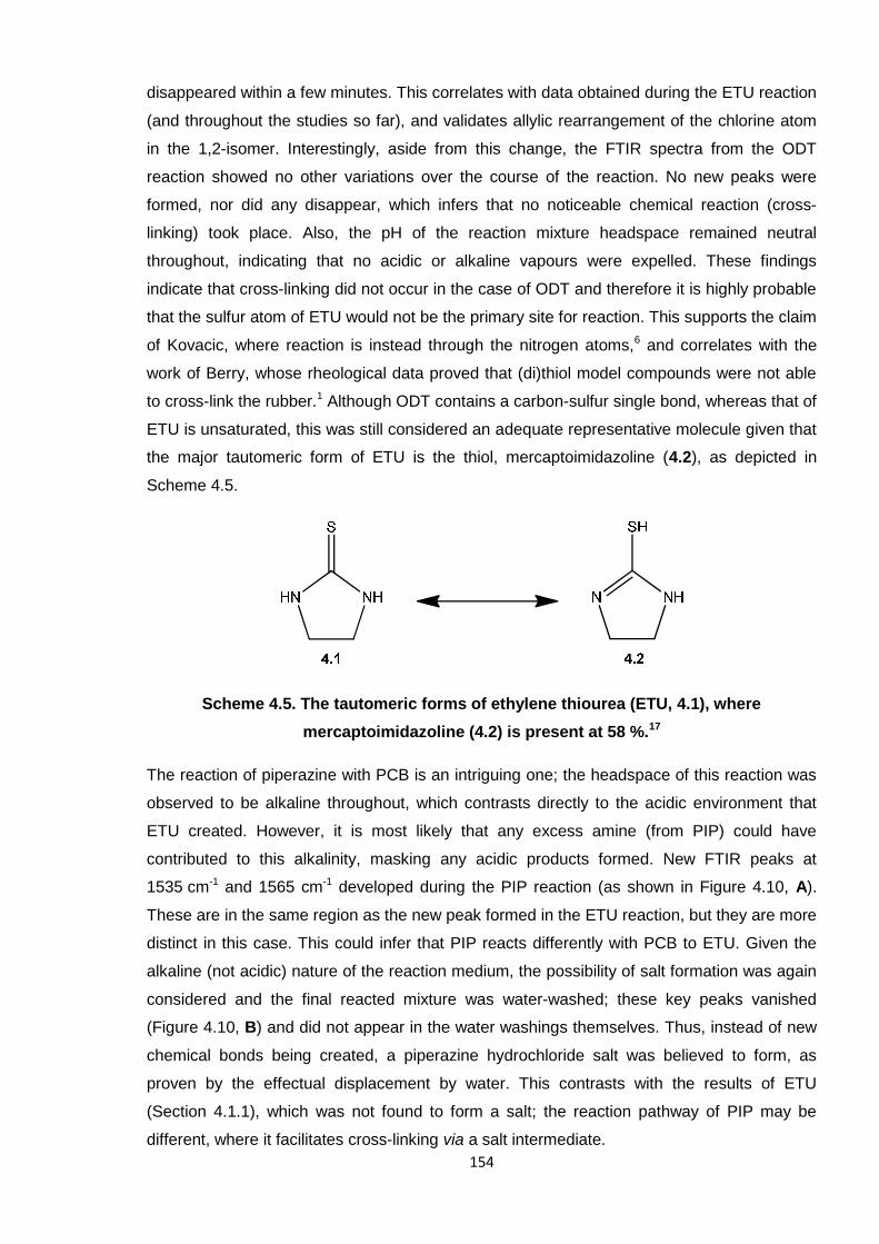
the major tautomeric form of ETU is the thiol, mercaptoimidazoline (4.2), as depicted in
Scheme 4.5.
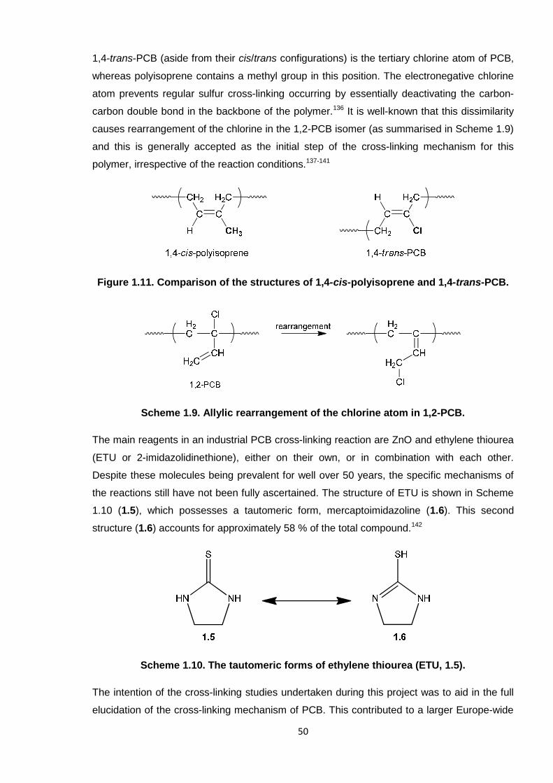
Scheme 4.5. The tautomeric forms of ethylene thiourea (ETU, 4.1), where
mercaptoimidazoline (4.2) is present at 58 %.17
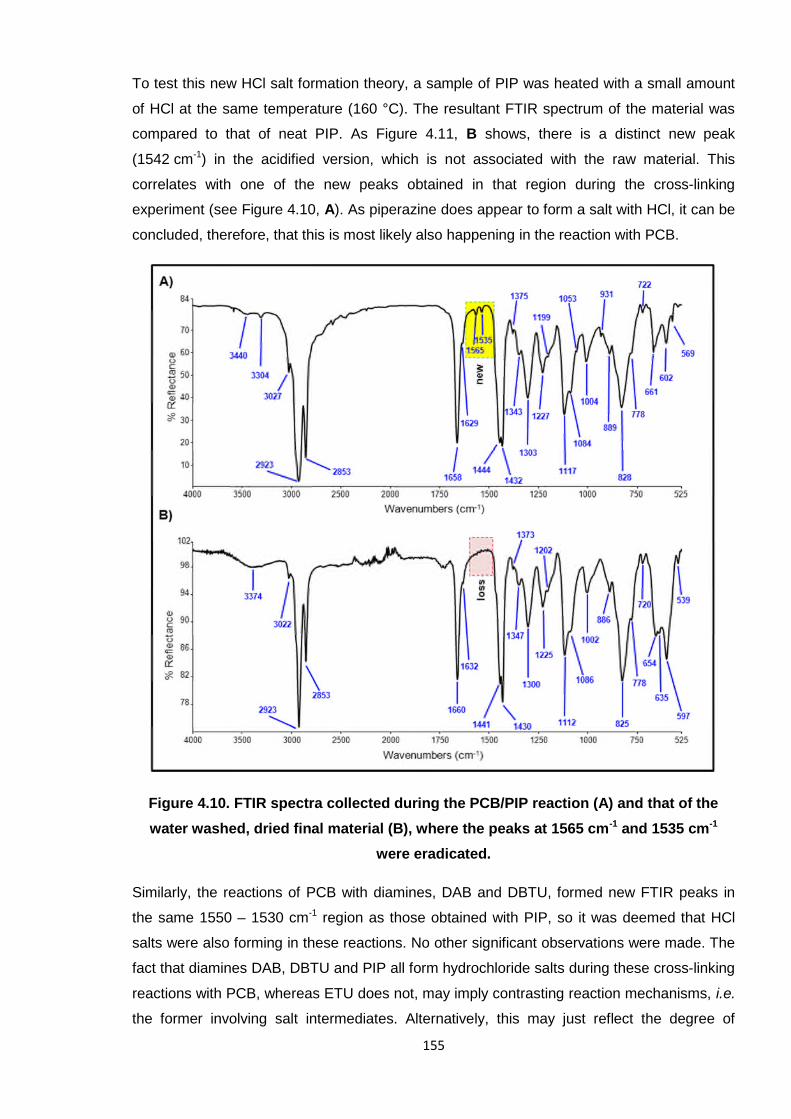
The reaction of piperazine with PCB is an intriguing one; the headspace of this reaction was
observed to be alkaline throughout, which contrasts directly to the acidic environment that
ETU created. However, it is most likely that any excess amine (from PIP) could have
contributed to this alkalinity, masking any acidic products formed. New FTIR peaks at
1535 cm-1 and 1565 cm-1 developed during the PIP reaction (as shown in Figure 4.10, A).
These are in the same region as the new peak formed in the ETU reaction, but they are more
distinct in this case. This could infer that PIP reacts differently with PCB to ETU. Given the
alkaline (not acidic) nature of the reaction medium, the possibility of salt formation was again
considered and the final reacted mixture was water-washed; these key peaks vanished
(Figure 4.10, B) and did not appear in the water washings themselves. Thus, instead of new
chemical bonds being created, a piperazine hydrochloride salt was believed to form, as
proven by the effectual displacement by water. This contrasts with the results of ETU
(Section 4.1.1), which was not found to form a salt; the reaction pathway of PIP may be
different, where it facilitates cross-linking via a salt intermediate.
155
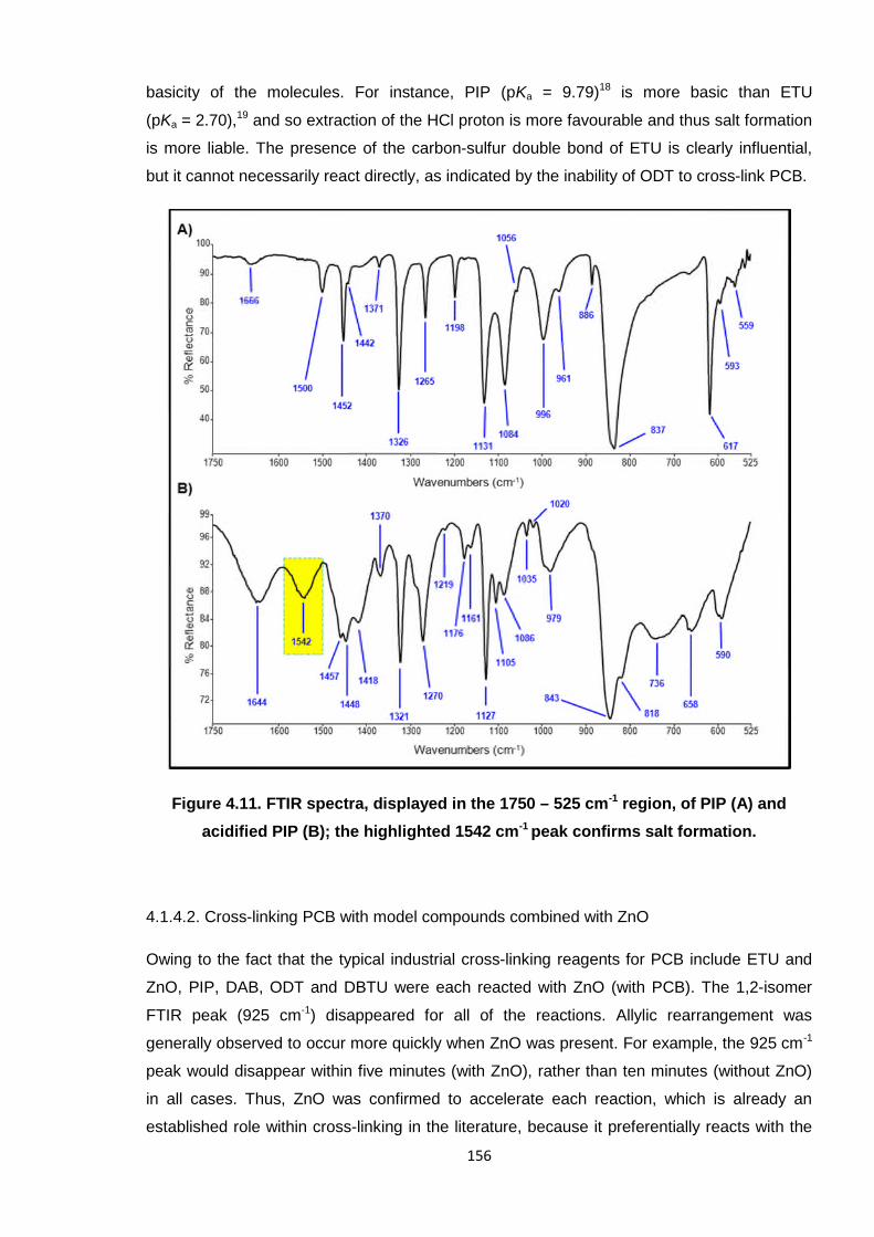
To test this new HCl salt formation theory, a sample of PIP was heated with a small amount
of HCl at the same temperature (160 °C). The resultant FTIR spectrum of the material was
compared to that of neat PIP. As Figure 4.11, B shows, there is a distinct new peak
(1542 cm-1) in the acidified version, which is not associated with the raw material. This
correlates with one of the new peaks obtained in that region during the cross-linking
experiment (see Figure 4.10, A). As piperazine does appear to form a salt with HCl, it can be
concluded, therefore, that this is most likely also happening in the reaction with PCB.
Figure 4.10. FTIR spectra collected during the PCB/PIP reaction (A) and that of the
water washed, dried final material (B), where the peaks at 1565 cm-1 and 1535 cm-1
were eradicated.
Similarly, the reactions of PCB with diamines, DAB and DBTU, formed new FTIR peaks in
the same 1550 – 1530 cm-1 region as those obtained with PIP, so it was deemed that HCl
salts were also forming in these reactions. No other significant observations were made. The
fact that diamines DAB, DBTU and PIP all form hydrochloride salts during these cross-linking
reactions with PCB, whereas ETU does not, may imply contrasting reaction mechanisms, i.e.
the former involving salt intermediates. Alternatively, this may just reflect the degree of
156
basicity of the molecules. For instance, PIP (pKa = 9.79)18 is more basic than ETU
(pKa = 2.70),19 and so extraction of the HCl proton is more favourable and thus salt formation
is more liable. The presence of the carbon-sulfur double bond of ETU is clearly influential,
but it cannot necessarily react directly, as indicated by the inability of ODT to cross-link PCB.
Figure 4.11. FTIR spectra, displayed in the 1750 – 525 cm-1 region, of PIP (A) and
acidified PIP (B); the highlighted 1542 cm-1 peak confirms salt formation.
4.1.4.2. Cross-linking PCB with model compounds combined with ZnO
Owing to the fact that the typical industrial cross-linking reagents for PCB include ETU and
ZnO, PIP, DAB, ODT and DBTU were each reacted with ZnO (with PCB). The 1,2-isomer
FTIR peak (925 cm-1) disappeared for all of the reactions. Allylic rearrangement was
generally observed to occur more quickly when ZnO was present. For example, the 925 cm-1
peak would disappear within five minutes (with ZnO), rather than ten minutes (without ZnO)
in all cases. Thus, ZnO was confirmed to accelerate each reaction, which is already an
established role within cross-linking in the literature, because it preferentially reacts with the
157
1,2-PCB isomer.13 This is reportedly accredited to the zinc dication, Zn2+, which can complex
with sulfur-containing cross-linking additives,13 as discussed in Section 1.2.1.2.
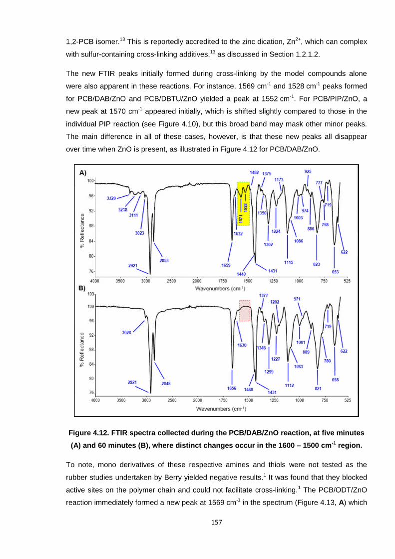
The new FTIR peaks initially formed during cross-linking by the model compounds alone
were also apparent in these reactions. For instance, 1569 cm-1 and 1528 cm-1 peaks formed
for PCB/DAB/ZnO and PCB/DBTU/ZnO yielded a peak at 1552 cm-1. For PCB/PIP/ZnO, a
new peak at 1570 cm-1 appeared initially, which is shifted slightly compared to those in the
individual PIP reaction (see Figure 4.10), but this broad band may mask other minor peaks.
The main difference in all of these cases, however, is that these new peaks all disappear
over time when ZnO is present, as illustrated in Figure 4.12 for PCB/DAB/ZnO.
Figure 4.12. FTIR spectra collected during the PCB/DAB/ZnO reaction, at five minutes
(A) and 60 minutes (B), where distinct changes occur in the 1600 – 1500 cm-1 region.
To note, mono derivatives of these respective amines and thiols were not tested as the
rubber studies undertaken by Berry yielded negative results.1 It was found that they blocked
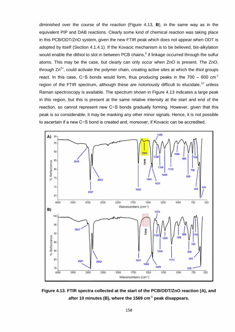
active sites on the polymer chain and could not facilitate cross-linking.1 The PCB/ODT/ZnO
reaction immediately formed a new peak at 1569 cm-1 in the spectrum (Figure 4.13, A) which
158
diminished over the course of the reaction (Figure 4.13, B), in the same way as in the
equivalent PIP and DAB reactions. Clearly some kind of chemical reaction was taking place
in this PCB/ODT/ZnO system, given the new FTIR peak which does not appear when ODT is
adopted by itself (Section 4.1.4.1). If the Kovacic mechanism is to be believed, bis-alkylation
would enable the dithiol to slot in between PCB chains,6 if linkage occurred through the sulfur
atoms. This may be the case, but clearly can only occur when ZnO is present. The ZnO,
through Zn2+, could activate the polymer chain, creating active sites at which the thiol groups
react. In this case, C−S bonds would form, thus producing peaks in the 700 – 600 cm-1
region of the FTIR spectrum, although these are notoriously difficult to elucidate,12 unless
Raman spectroscopy is available. The spectrum shown in Figure 4.13 indicates a large peak
in this region, but this is present at the same relative intensity at the start and end of the
reaction, so cannot represent new C−S bonds gradually forming. However, given that this
peak is so considerable, it may be masking any other minor signals. Hence, it is not possible
to ascertain if a new C−S bond is created and, moreover, if Kovacic can be accredited.
Figure 4.13. FTIR spectra collected at the start of the PCB/ODT/ZnO reaction (A), and
after 10 minutes (B), where the 1569 cm-1 peak disappears.
159
4.1.4.3. Cross-linking PCB with tetrabutylthiuram disulfide (TbuT)
To again imitate the studies of Berry,1 a set of reactions were further performed on PCB with
a thiuram-based standard rubber accelerator, tetrabutylthiuram disulfide (TbuT). This
particular compound is a known cross-linker, both in the raw form and when complexed with
the Zn2+ dication.2, 3 On reacting PCB with TbuT and monitoring the reaction periodically by
FTIR, no new peaks in the spectrum were observed to form, which would otherwise indicate
new bond formation. However, as Figure 4.14 shows, the signal at 1486 cm-1, ascribed to the
carbon-nitrogen bond of the N−C=S functionality,12 diminishes completely after 30 minutes.
Hence, the structure of TbuT is clearly being altered in some way, although it is difficult to
visualise exactly how from these data alone. Also, the peak for the 1,2-isomer, at 924 cm-1,
disappears within this time, as is common throughout all of the reactions undertaken with
PCB thus far.
Figure 4.14. FTIR spectra collected during the PCB/TbuT reaction, where the 1486 cm-1
peak at the start (A) disappears within 30 minutes (B).
160
4.1.4.4. Cross-linking PCB with tetrabutylthiuram disulfide (TbuT) combined with ZnO
In the same manner as the investigations with ETU and model compounds, TbuT was also
reacted with PCB in conjunction with ZnO. Firstly, the aforementioned key peaks (in Section
4.1.4.3), namely those at 924 cm-1 and 1486 cm-1, both also diminished in this case, albeit at
a faster rate. Thus, whatever the nature of the reaction, it was being accelerated by the
presence of the metal oxide, although it is not known how the ZnO was affecting the
1484 cm-1 peak exactly. Acceleration was also found to occur between ETU and the model
compounds (separately) with ZnO.
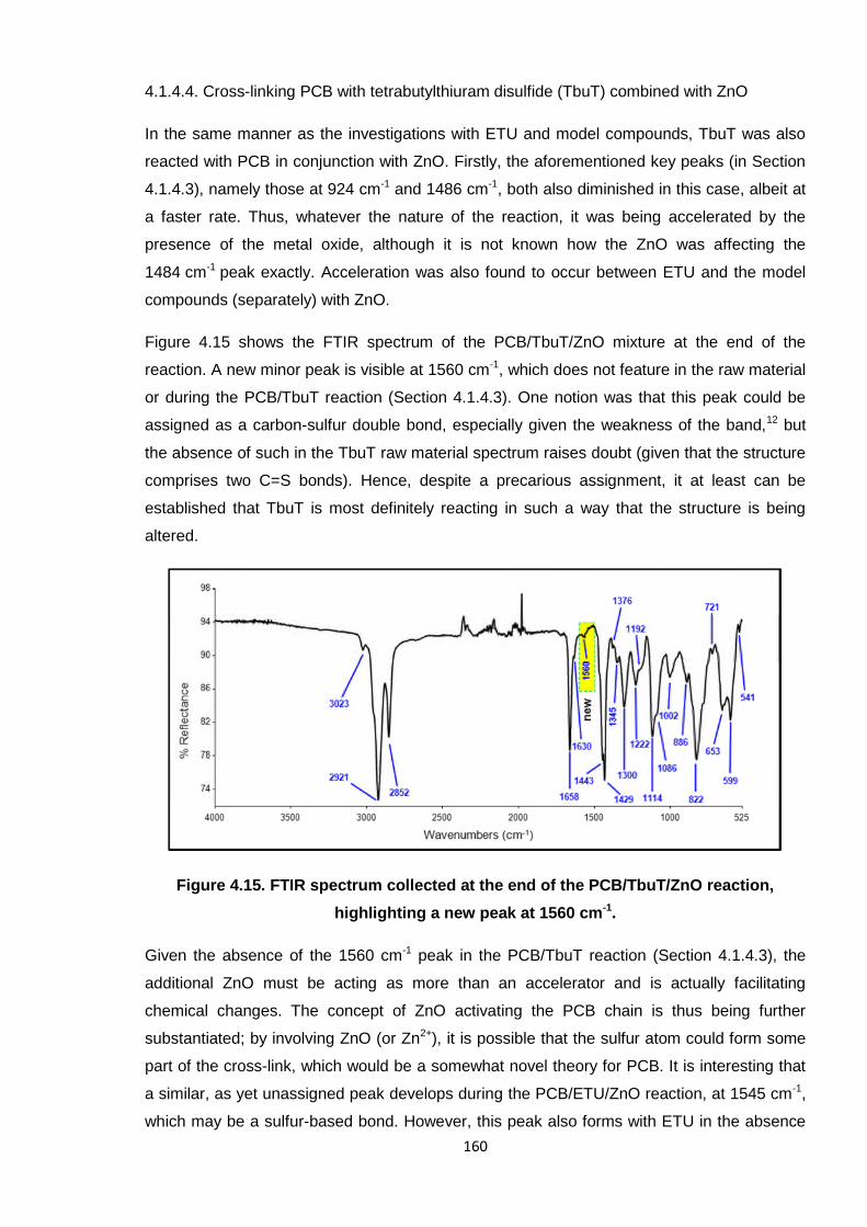
Figure 4.15 shows the FTIR spectrum of the PCB/TbuT/ZnO mixture at the end of the
reaction. A new minor peak is visible at 1560 cm-1, which does not feature in the raw material
or during the PCB/TbuT reaction (Section 4.1.4.3). One notion was that this peak could be
assigned as a carbon-sulfur double bond, especially given the weakness of the band,12 but
the absence of such in the TbuT raw material spectrum raises doubt (given that the structure
comprises two C=S bonds). Hence, despite a precarious assignment, it at least can be
established that TbuT is most definitely reacting in such a way that the structure is being
altered.
Figure 4.15. FTIR spectrum collected at the end of the PCB/TbuT/ZnO reaction,
highlighting a new peak at 1560 cm-1.
Given the absence of the 1560 cm-1 peak in the PCB/TbuT reaction (Section 4.1.4.3), the
additional ZnO must be acting as more than an accelerator and is actually facilitating
chemical changes. The concept of ZnO activating the PCB chain is thus being further
substantiated; by involving ZnO (or Zn2+), it is possible that the sulfur atom could form some
part of the cross-link, which would be a somewhat novel theory for PCB. It is interesting that
a similar, as yet unassigned peak develops during the PCB/ETU/ZnO reaction, at 1545 cm-1,
which may be a sulfur-based bond. However, this peak also forms with ETU in the absence
161
of ZnO. This disparity may be due to contrasting reactivities of TbuT and ETU, and the sulfur
atoms being potentially more/less available to react. For instance, the structure of TbuT
(shown in Table 4.3) contains a disulfide bridge between the thiocarbonyl groups, whereas
the sole sulfur of ETU is directly bonded to the five-membered ring. Cleavage of the central
TbuT sulfur-sulfur bond may occur (facilitated by Zn2+) and the reaction would then proceed
through the liberated sulfur atoms (S-). This cannot happen to the sulfur of ETU (C=S), so the
reaction would not proceed in the same way; the reaction of PCB with ETU clearly does not
need ZnO to activate some new type of sulfur-based bond.
4.1.5. Conclusions for the current cross-linking mechanism of poly(2-chloro-1,3-
butadiene)
Considering the collective data presented herein for the PCB cross-linking studies, it is now
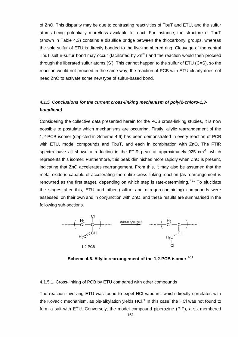
possible to postulate which mechanisms are occurring. Firstly, allylic rearrangement of the
1,2-PCB isomer (depicted in Scheme 4.6) has been demonstrated in every reaction of PCB
with ETU, model compounds and TbuT, and each in combination with ZnO. The FTIR
spectra have all shown a reduction in the FTIR peak at approximately 925 cm-1, which
represents this isomer. Furthermore, this peak diminishes more rapidly when ZnO is present,
indicating that ZnO accelerates rearrangement. From this, it may also be assumed that the
metal oxide is capable of accelerating the entire cross-linking reaction (as rearrangement is
renowned as the first stage), depending on which step is rate-determining.7-11 To elucidate
the stages after this, ETU and other (sulfur- and nitrogen-containing) compounds were
assessed, on their own and in conjunction with ZnO, and these results are summarised in the
following sub-sections.
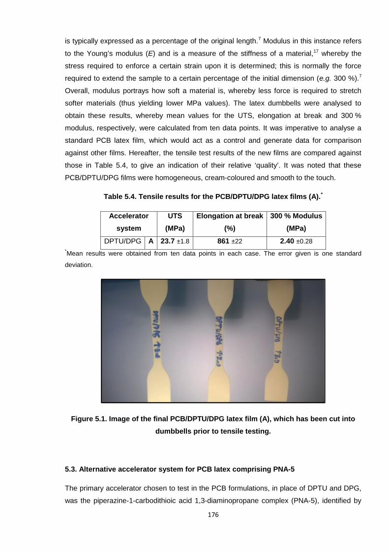
Scheme 4.6. Allylic rearrangement of the 1,2-PCB isomer.7-11
4.1.5.1. Cross-linking of PCB by ETU compared with other compounds
The reaction involving ETU was found to expel HCl vapours, which directly correlates with
the Kovacic mechanism, as bis-alkylation yields HCl.6 In this case, the HCl was not found to
form a salt with ETU. Conversely, the model compound piperazine (PIP), a six-membered
H2C C
CHH2C
ClH2C C
CHH2C
Cl
rearrangement
1,2-PCB
162
cyclic diamine, was found to form a hydrochloride salt. These contrasting trends infer
different reaction pathways for ETU and PIP, where the mechanism of the latter may be via a
salt intermediate. The carbon-sulfur double bond of ETU is presumably rendering the
nitrogen atoms of the molecule less basic, thus preventing them from forming a salt.
It has been deduced that the sulfur of ETU cannot react with the polymer chain directly in the
absence of ZnO. The lack of reaction by 1,8-octanedithiol (ODT) with PCB helps to prove this
and in turn supports the claim of Kovacic. However, ODT was capable of reacting in the
presence of ZnO. It is therefore apparent that ZnO not only accelerates the reaction rate, but
also helps to facilitate a reaction through sulfur, that is, the thiol group of ODT (versus C=S of
ETU, which is admittedly chemically different).
The existing theories concerning cross-linking by ZnO alone have, on the whole, been
disproved. An ether linkage was not substantiated, nor was the formation of ZnCl2, which
would otherwise verify the claims detailed by Aprem,14 Desai7 and Vukov,15 respectively.
Likewise, it was not possible to prove diene cross-links (Vukov),15 as new carbon-carbon
double bonds were not found to form during the ZnO reaction.
The studies undertaken with tetrabutylthiuram disulfide (TbuT) showed that the N−C=S
functionality was disrupted in some way during cross-linking. An FTIR peak pertaining to this
part of the structure of the molecule diminished over time, most readily when ZnO
accompanied the mixture. The presence of ZnO also enabled a new type of bond to form, as
demonstrated by a new FTIR peak (1560 cm-1), which was understood to represent a C−S
bond. This evidence therefore suggests that ZnO is altering the accelerator composition and
enabling cross-linking through sulfur (which is not possible in the absence of ZnO).
4.1.5.2. The ETU/ZnO mechanism of cross-linking PCB
There is strong evidence that there is not one single ETU/ZnO cross-linking mechanism for
PCB. It is most likely that the ETU bis-alkylation mechanism of Kovacic6 is indeed in effect,
as indicated, for instance, by the acidic environment ETU generates. Additionally, the Pariser
mechanism (shown previously in Scheme 4.4),16 which is the only report of the effect of ETU
and ZnO in unison, has been partially proven through the formation of ZnCl2 and EU. Low
molecular weight PCB was reacted with ETU and ZnO, whereby a white solid was furnished.
This was elucidated as the product of an ETU/ZnCl2 reaction, thus proving that ZnCl2 had
formed in situ (via HCl and ZnO). EU was discovered separately by Berry with PCB rubber.1
Although the same species are produced as those proposed by Pariser,16 it is not possible
that the reaction mechanism proceeds in exactly the same manner. Crucially, it is unlikely
163
that sulfur reacts directly with the polymer chain, as ODT could not react on its own and
(di)thiols were unable to cross-link the rubber by themselves.1 However, the addition of ZnO
changed the reactivity of the systems, enabling ODT to react and facilitating changes with
TbuT, where new carbon-sulfur bonds were deemed to form in the latter. Thus, it is believed
that ZnO activates the polymer chain towards reaction with sulfur.
Schemes 4.7 and 4.8 display the two mechanisms which have been proven to occur in the
cross-linking of PCB with ETU and ZnO, including that of Kovacic6 and a novel proposal.20 All
three are proposed as simultaneously occurring mechanisms, hence the complications which
have arisen during the elucidation, overall. The first step for each is rearrangement of the
1,2-isomer. In the case of the new mechanism (4.8), the polymer chain becomes activated by
ZnO, where the PCB chlorine atom is replaced by oxygen. This makes it possible for the
sulfur-containing species to interact and effectively displace oxygen, thus generating EU. As
a result, a new carbon-sulfur bond forms as the cross-link and ZnCl2 is released. The last
stage of this mechanism is comparable to Pariser (see Scheme 4.4),16 but, vitally, ZnO has
here been found to react before ETU. The newly-suggested mechanism (4.8) was realised
during this project which ran alongside that of Berry,1 whereby the rubber and oligomeric
PCB studies (the former undertaken at RBL; the latter at Aston University) complemented
each other. Without the aid of these particular studies described here, especially regarding
the observation of by-products, it would not have been possible to make such a discovery.
Scheme 4.7. The Kovacic mechanism of cross-linking PCB with ETU and ZnO in
unison.6
H2C C
CHH2C
H2C C
CHH2C
N
NS
H2C C
CHH2C
ClH2C C
CHH2C
Cl1,2-PCB
NHHN
S
2HCl
22rearrangement
ZnO
ETU
164
Scheme 4.8. The new mechanism of cross-linking PCB by ETU and ZnO in unison,20
which is similar to that of Pariser.16
H2C C
CHH2C
Cl
H2C C
CHH2C
O
Zn
O
NHHN
S
NHHN
S
H2C C
CHH2C
O
NH
HN
S
H2C C
CHH2C
S
NH
HN
O
rearranged1,2-PCB
H2C C
CHH2C
Cl
H2C C
CHH2C
S
Zn
Cl
H2C C
CHH2C
S
H2C C
CHH2C
ZnCl2
H2C C
CHH2C
Clrearrangement
ZnO
ETU
NHHN
O
EU
Zn Cl- -2+
Zn Cl- -2+
Zn Cl-2+-
165
4.1.6. Towards a safer accelerator system for cross-linking poly(2-chloro-1,3-
butadiene)
This PhD project, and that of Berry,1 was supported by Robinson Brothers Ltd. (RBL), who
were funded by a European project entitled SafeRubber.21 Involving several companies and
academic institutions, the principal objective of SafeRubber was to identify and produce an
alternative PCB rubber cross-linker to the hazardous reagent ETU.22-25 Achieving this was
primarily undertaken through RBL and Aston collaborating to elucidate the current cross-
linking mechanism, which would then shed light on how an alternative molecule should
function. To complete this section on cross-linking, it is appropriate to now summarise how
the project has achieved this aim, on the whole.
As concluded in the previous section (4.1.5.2), the bis-alkylation mechanism of Kovacic6 and
a modified Pariser mechanism20 have been deemed to occur in the standard industrial
ETU/ZnO cross-linking system for PCB. In the latter, ZnO was deemed crucial in activating
the polymer chain towards cross-linking through sulfur and in facilitating prompt
rearrangement of the 1,2-isomer.
Interestingly, during these studies it was found that DBTU and model diamine compounds,
PIP and DAB, caused cross-linking, as did the thiuram-based accelerator, TbuT. PIP, DAB
and DBTU formed hydrochloride salts when ZnO was absent; in the presence of the metal
oxide, no such salts existed as the FTIR peaks originally pertaining to such, in the 1600 –
1500 cm-1 region, disappeared over time. The N−C=S functionality of TbuT was disrupted
during the reaction with PCB, with and without ZnO; a carbon-sulfur bond was believed to
form when ZnO was present. All of these combined data inspired the prospect that the
alternative cross-linker (to ETU) should comprise a diamine, which would function by
removing the chlorine atom of the polymer and thus activate the chain. Additionally, a sulfur-
based compound would provide the cross-link atom/s.
A collection of potential new accelerators (PNAs) was devised by the SafeRubber consortium
(RBL and the various European project partners) and are listed in Table 4.4. These
molecules each comprised a cross-linker (sulfur-containing) component and an amine-based
activator. The theory behind this concoction was that the diamine would separate from the
complex during curing (i.e. on heating), activate the polymer chain and then the sulfur-
compound would be able to react with the polymer chain in a similar manner to ETU, via
sulfur (see Scheme 4.8 in Section 4.1.5.2). It was the role of the University of
Milano-Bicocca, Italy, to screen these various molecules regarding their potential hazardous
properties using select computer-simulated models. Quantitative structure-property (QSPR)
and quantitative structure-activity relationship (QSAR) data correlated each structure with
specific processes, such as chemical reactivities, and concluded on their suitability to this
166
particular role (in cross-linking PCB). In this case, all of the listed compounds gave promising
results and were deemed not mutagenic or carcinogenic in nature, and were not possible
(human) skin sensitisers.
Table 4.4. List of original potential new accelerators (PNAs) for cross-linking PCB,
designated by the SafeRubber consortium.
Abbreviation Cross-linker Activator
PNA-1
PNA-2
PNA-3*
PNA-4
PNA-5
PNA-6
PNA-7
*PNA-3 comprises only one cross-linker molecule and one activator molecule.
These compounds were comprehensively tested by Berry at RBL to assess their ability in
curing PCB rubber;1 the most promising tensile and rheological data resulted from PNA-5,
which afforded similar results to the ETU system for PCB. Structurally, PNA-5 comprises a
1,3-diaminopropane linear chain and a piperazine-based dithiocarbamate. The N−C=S
functionality compares to that in the TbuT structure when it forms a complex with the Zn2+
167
dication, as shown in Figure 4.16. This, along with the piperazine ring, appears to be a good
combination of the molecules tested in these studies (PIP, TbuT and alkyl diamines) which
were all found to successfully cross-link PCB oligomer (and rubber) without the need for
ZnO.
Figure 4.16. Comparison of Zn2+-complexed TbuT and PNA-5 structures, where Bu
denotes a linear butyl group.
The FTIR spectrum of pure PNA-5 is provided in Figure 4.17 (A). NH3+ bending is highlighted
at 3169 cm-1 and the N−C=S functionality is confirmed by the peak at 1458 cm-1.12 This new
compound was adopted in analogous cross-linking experiments to the studies of Berry,1
incorporating the low molecular weight PCB. Distinct changes in the FTIR spectrum during
the reaction are illustrated in Figure 4.17 (B) where new peaks were afforded at 1537 cm-1
and 1565 cm-1. Variations within this particular region (1600 – 1500 cm-1) were observed
throughout the studies herein, with ETU, model compounds and TbuT. Notably, the
1458 cm-1 peak in the raw material was not observed in the curing mixture at any point during
the ‘cross-linking’ reaction, so it was not possible to determine what befell the N−C=S bond.
It is possible that this peak, being relatively insignificant, has been masked by parent polymer
peaks, in this instance.
PNA-5 was also reacted with PCB in combination with ZnO. In the work of Berry,1 the rubber
material afforded similar rheological properties to that cured with ETU/ZnO. Here, in the low
molecular weight PCB, the FTIR indicated that new peaks formed at 3209 cm-1 and
3175 cm-1, which are located in the same region as the NH3+ bending of the PNA-5 raw
material (see Figure 4.17, A), which implies that the nitrogen atoms are potentially being
involved in the reaction. Also, the 1574 cm-1 peak is a new addition and is again situated in
that same area where changes have been noticeable throughout these studies. An in situ
spectrum is displayed in Figure 4.18 with these peaks highlighted.
168
Figure 4.17. FTIR spectrum of PNA-5 (A) and representative spectrum collected during
a PCB/PNA-5 cross-linking reaction (B).
Figure 4.18. Representative FTIR spectrum collected during the PCB/PNA-5/ZnO
cross-linking reaction, with newly formed peaks highlighted.
169
A secondary aim of the SafeRubber21 project was to reduce the level of ZnO in the industrial
PCB cross-linking formulation, as this reagent also poses environmental hazards. Hence, a
multi-functional additive (MFA) was adopted in place of ZnO to further optimise the PNA-5
system. As defined in the Introduction Chapter (Section 1.2.1.3), MFAs comprise a fatty acid-
diamine complex; this type of compound can activate cross-linking and aid the processing of
the rubber material.26 Crucially, many MFAs are non-toxic and are already well-known to
industry. In particular, 1,4-MFA (Figure 4.19) is based on a 1:2 stoichiometric ratio of
1,4-diaminobutane (DAB) and stearic acid (C18 saturated fatty acid).
Figure 4.19. Structure of 1,4-MFA.
1,4-MFA was found to cross-link PCB rubber by Berry, independently and in combination
with PNA-5, whereby the latter afforded similar tensile results as the rubber cured by the
original ETU/ZnO system.1 Hence, the initial objective to replace ETU was successfully met
and the additional bonus of eradicating ZnO was made possible. Thus, a new, safer
accelerator system for PCB has been successfully devised through the combined efforts of
Aston University, RBL and the various SafeRubber partners.21 The PNA-5/1,4-MFA system is
undergoing further comprehensive tests with PCB rubber, so that this combination will
potentially be adopted worldwide in the future.
4.2. References
1. K. I. Berry, The Quest for a Safer Accelerator for Polychloroprene Rubber, PhD Thesis, AstonUniversity, Birmingham, 2013.
2. C. W. Evans, Practical Rubber Compounding and Processing, Applied Science Publishers,London, 1981.
3. G. Odian, in Elastomers and Rubber Elasticity, ACS Symposium Series, 1982, vol. 193, ch. 1,pp. 1-31.
4. T. Yoshida, Mater. Trans., 2003, 44, 2489-2493.5. K. O. Calvert, in Polymer Latices and their Applications, ed. K. O. Calvert, Applied Science
Publishers, London, 1982, pp. 1-10.6. P. Kovacic, Ind. Eng. Chem. Res., 1955, 47, 1090-1094.7. H. Desai, K. G. Hendrikse and C. D. Woolard, J. Appl. Polym. Sci., 2007, 105, 865-876.8. P. E. Mallon, W. J. McGill and D. P. Shillington, J. Appl. Polym. Sci., 1995, 55, 705-721.9. Y. Miyata and M. Atsumi, Rubber Chem. Technol., 1989, 62, 1-12.10. I. Kuntz, R. L. Zapp and R. J. Pancirov, Rubber Chem. Technol., 1984, 57, 813-825.11. Y. Miyata and M. Atsumi, J. Polym. Sci. Part A: Polym. Chem., 1988, 26, 2561-2572.12. R. M. Silverstein, G. C. Bassler and T. C. Morrill, Spectrometric Identification of Organic
Compounds, Wiley, Singapore, 1991.13. G. Heideman, R. N. Datta, J. W. M. Noordermeer and B. v. Baarle, J. Appl. Polym. Sci., 2005,
95, 1388-1404.
170
14. A. S. Aprem, K. Joseph and S. Thomas, Rubber Chem. Technol., 2005, 78, 458-488.15. R. Vukov, Rubber Chem. Technol., 1984, 57, 284-290.16. R. Pariser, Kunststoffe, 1960, 50, 623-627.17. L. Krause and M. A. Whitehead, Mol. Phys., 1973, 25, 99-111.18. D. D. Perrin, Aust. J. Chem., 1964, 17, 484-488.19. L. Zhou, X. Liu, S. Kang, F. Zhang and C. Pan, Food Chemistry, 2013, 138, 1355-1359.20. K. I. Berry, M. Liu, K. Chakraborty, N. Pullan, A. West, C. Sammon and P. D. Topham, Rubber
Chem. Technol., 2014, Accepted.21. SafeRubber, http://www.saferubber.eu/, Accessed 11/03/2014.22. D. M. Smith, Occup. Med., 1976, 26, 92-94.23. D. M. Smith, Br. J. Ind. Med., 1984, 41, 362-366.24. R. S. Chhabra, S. Eustis, J. K. Haseman, P. J. Kurtz and B. D. Carlton, Fundam. Appl.
Toxicol., 1992, 18, 405-417.25. J. Ashby, Mutagenesis, 1986, 1, 3-16.26. G. Heideman, J. W. M. Noordermeer and R. N. Datta, Rubber Chem. Technol., 2006, 79, 561-
588.
171
CHAPTER 5
POLY(2-CHLORO-1,3-BUTADIENE)
LATEX DEVELOPMENT
172
5. Poly(2-chloro-1,3-butadiene) latex development
The second industrial component of this PhD project concerned the development of poly(2-
chloro-1,3-butadiene) (PCB) latex films. It was the overall aim of Robinson Brothers Ltd.
(RBL) to eventually replace the standard thiourea/guanidine-based accelerator system in the
manufacture of PCB latex rubber with safer, non-toxic reagents. This is a similar concept to
that for the cross-linking studies performed on PCB oligomers and rubber (detailed
previously in Chapter 4), where ethylene thiourea (ETU) was the primary concern.
5.1. Introduction
PCB latex is a diverse material, being adopted in coatings, adhesives and automotive parts,
for example,1, 2 (as previously reviewed in Section 1.3.3.2). One of the most important
applications, however, is in the manufacture of latex gloves. Natural rubber (NR) has been
prominent in this field, historically, but the focus has shifted to other materials owing to the
fact that residual proteins within NR can leach out of the material and cause skin allergies
amongst users.3 PCB latex rubber has been deemed a suitable alternative material, as
harmful proteins are absent in the first place and so the material is safer overall; PCB gloves
are less likely to afford skin dermatitis or cause skin sensitivity.3
The safety of latex gloves is of paramount importance as such items are widely used in the
public services and scientific professions, ultimately acting as a protective barrier to the skin.2
Certain chemicals used in the production of latex rubber are the primary offenders in terms of
causing skin problems amongst glove wearers; it is not the latex rubber itself which causes
direct harm to the skin.4 A review by Rose et al. highlights accelerator compounds as
generally the most harmful type of additives within a latex formulation,5 whereby the (human)
patch test studies of Geier et al. have revealed that thiuram derivatives most regularly cause
problems.6
Table 5.1 illustrates the main reagents employed throughout these latex studies, which were
incorporated as aqueous dispersions. As detailed in Section 1.3.3.1, accelerators are
responsible for linking polymer chains and creating the cross-linked network. Fillers are
responsible for providing abrasive resistance in the final material and surfactants are wholly
involved in stabilising the system. Antioxidants are present to aid in preventing degradation
of the final rubber material, such as by UV, heat, etc.2 To note, this part of the project utilised
commercially available, pre-prepared PCB in the form of an emulsion; it was not necessary
to synthesise polymer for these studies.
173
Table 5.1. Individual components in the PCB latex formulations.
ReagentDispersion level
(% w/w)Function
ZnO 50 accelerator
Aquanox 2246 45 antioxidant
Kaolin clay 40 filler, processing aid
Darvan® SMO 30surfactants
Darvan® WAQ 25
For these experiments, the reagents listed in Table 5.1 were added to the PCB emulsion,
along with the appropriate accelerator compounds, and the dipping procedure described in
Chapter 2 (Section 2.2.6) was employed to produce the PCB latex films. During this process
a mould, or ‘former’, was submerged into the latex formulation and a coating materialised on
the surface. Subsequent leaching, drying and thermal cross-linking (curing) stages were then
undertaken to generate the final films. The focus of these studies was the accelerator system
within the PCB formulation, whereby several variations were employed. Table 5.2 lists the
accelerators which were trialled, alongside their adopted abbreviations and chemical
structures.
This eclectic mix of accelerators includes DPG and DPTU, which together form the standard
guanidine/thiourea system typically employed in the industrial production of PCB latex
gloves;7 crucially, these molecules have been identified as skin allergens by Geier et al.6
Also included in the research was the molecule which transpired from the SafeRubber
consortium (PNA-5, see Chapter 4),8 a thiuram disulfide (TBzTD), a xanthogen polysulfide
(DIXP) and a completely novel compound (PNA-8) which was developed at RBL. Various
combinations of these compounds were assessed in the PCB formulations, whereby ZnO
was also present as an activator (of polymer chains towards cross-linking). Each accelerator
system is rationalised in the corresponding results section and each batch (or experiment) is
denoted by an individual character, namely ‘A’, ‘B’, ‘C’, etc.
On the whole, there is scarce literature concerning studies specifically on PCB latex
materials. A recent report by Rattanasom et al. describes ultrasonication as an effective
method to disperse additives optimally within the formulation, but it does not focus on the
nature of the accelerators.9 It is suspected that the lack of relevant literature is associated
with the sensitivity of such information within industry and companies not wishing to disclose
their technology to competitors. The research described in this chapter was an entirely new
174
venture for the industry sponsor of the project, RBL, and was anticipated to initiate a new
area of interest for their line of rubber additive products.
Table 5.2. Accelerators adopted in the PCB latex formulations.
Accelerator name Abbreviation Structure
Diphenyl thiourea DPTU
Diphenyl guanidine DPG
Piperazine-1-carbodithioic
acid 1,3-diaminopropane
complex
PNA-5
2,2'-Dithio
di(ethylammonium)-
bis(dibenzyldithiocarbamate)
PNA-8
Diisopropyl xanthogen
polysulfideDIXP
Tetrabenzylthiuram disulfide TBzTD
5.2. PCB latex films from the standard DPTU/DPG accelerator system
PCB latex films were synthesised in the first instance using the ‘industry-standard’
accelerator system. It was intended that the physical (tensile) test results from these films
would yield benchmark data which would be subsequently targeted. A binary organic
accelerator system comprising a thiourea derivative, DPTU, and a guanidine, DPG, was
adopted, with the addition of ZnO. These are the three accelerator components which are
used for preparing industrial PCB latex gloves.7 Table 5.3 lists the reagents in the formulation
in their entirety. Given that this work incorporated reagents as aqueous dispersions or
emulsions, several precise calculations were necessary to ensure that the final formulation
contained the appropriate minimum quantity of solids (total solids content, TSC). Throughout
this work, 40 % TSC was adopted, which is within the range recommended by Feast for PCB
latex (35 – 60 %).10 An exemplar table is provided in Section 2.2.5, which illustrates the
exact adjustments made for the ‘optimum’ formulation developed during this project. For
175
simplicity, the universal units of parts per hundred rubber (phr) are given for each experiment
throughout this chapter.
Table 5.3. Formulation details for the compounding of PCB/DPTU/DPG latex films (A).
ReagentPCB
latex
Darvan®
WAQZnO
Aquanox
2246
Kaolin
clay
Darvan®
SMODPTU DPG
Dispersion
level
(% w/w)
50 25 50 45 40 30 50 40
Quantity
(phr)A 100 0.3 5 1.5 10 1 2 2
The hazardous nature of certain sulfur- and nitrogen-containing accelerators has already
been discussed in the Introduction Chapter, regarding the curing of pure rubber and of
latexes (Sections 1.2.2.1 and 1.3.3.2, respectively). In general, thiurams have been identified
as the most harmful allergens associated with rubber latex gloves.6 Thiourea compounds
have also been highlighted as potential carcinogens, with particular emphasis on ethylene
thiourea (ETU),11-13 which includes the possible risk to the unborn foetuses of pregnant
women handling this chemical.14 Additional reference has been made, in the review by
Ashby,15 to the toxicity of other types of thiourea, such as diethyl thiourea and N,N'-
dicyclohexyl thiourea. Given that DPTU is a thiourea derivative, and that both DPTU and
DPG feature in the latex allergen list of Geier,6 there are concerns over PCB latexes
formulated using this standard accelerator system. This is the drive for these experiments, as
these compounds should be replaced. It was precautionary that this particular PCB latex
(involving DPTU/DPG, denoted as films A throughout) was compounded by a male co-
worker (M. Liu, RBL), given the potential damaging effect that thioureas can have on unborn
foetuses in the womb;14 the preparation (cutting) of the test dumbbells and subsequent
id="rpwp55nalysis was undertaken by the author. Table 5.4 illustrates the tensile results
obtained for these standard PCB films, as obtained through the use of a tensometer (details
of which are provided in the Experimental Chapter, Section 2.3.4).
The physical testing of the PCB rubber latex films required each sample to be cut into the
shapes of dumbbells, of a predefined size (as depicted in Figure 5.1), which were then
individually affixed in the tensometer and stretched until they ruptured. Ultimate tensile
strength (UTS) data reflect how resistant the material is to abrasion and tear;16 a high UTS
result is suggestive of a rigid, strong rubber with superior resilience. Elongation at break
describes the overall extension of the dumbbell which was achieved before it ruptured, which
176
is typically expressed as a percentage of the original length.7 Modulus in this instance refers
to the Young’s modulus (E) and is a measure of the stiffness of a material,17 whereby the
stress required to enforce a certain strain upon it is determined; this is normally the force
required to extend the sample to a certain percentage of the initial dimension (e.g. 300 %).7
Overall, modulus portrays how soft a material is, whereby less force is required to stretch
softer materials (thus yielding lower MPa values). The latex dumbbells were analysed to
obtain these results, whereby mean values for the UTS, elongation at break and 300 %
modulus, respectively, were calculated from ten data points. It was imperative to analyse a
standard PCB latex film, which would act as a control and generate data for comparison
against other films. Hereafter, the tensile test results of the new films are compared against
those in Table 5.4, to give an indication of their relative ‘quality’. It was noted that these
PCB/DPTU/DPG films were homogeneous, cream-coloured and smooth to the touch.
Table 5.4. Tensile results for the PCB/DPTU/DPG latex films (A).*
Accelerator
system
UTS
(MPa)
Elongation at break
(%)
300 % Modulus
(MPa)
DPTU/DPG A 23.7 ±1.8 861 ±22 2.40 ±0.28
*Mean results were obtained from ten data points in each case. The error given is one standard
deviation.
Figure 5.1. Image of the final PCB/DPTU/DPG latex film (A), which has been cut into
dumbbells prior to tensile testing.
5.3. Alternative accelerator system for PCB latex comprising PNA-5
The primary accelerator chosen to test in the PCB formulations, in place of DPTU and DPG,
was the piperazine-1-carbodithioic acid 1,3-diaminopropane complex (PNA-5), identified by
177
the SafeRubber consortium as a ‘safer’ alternative accelerator for PCB rubber (versus
ETU).8, 18 As explained previously in Chapter 4 (Section 4.1.6), computer-simulated studies
conducted by a project partner indicated that this compound was not carcinogenic and
subsequent experiments with low molecular weight PCB (oligomers) and the rubber proved it
to be an efficient cross-linker. Thus, PNA-5 was also examined in the PCB latex, on its own
and in combination with other accelerators.
All of the PNA molecules which materialised from the SafeRubber project (as listed
previously in Table 4.4 of Section 4.1.6), comprised two distinct sections to their structures.
The sulfur-containing portion acted as the cross-linker, whereas the (di)amine would activate
the polymer chain towards cross-linking. In order to facilitate this, the overall complexed
structure of the PNA would be disrupted when thermal cross-linking was initiated (i.e. on
heating the mixture), so that the amine molecule would become separated and subsequently
activate the polymer chain, in much the same way as ZnO was found to operate in the newly-
proposed mechanism of Berry et al. (illustrated previously in Scheme 4.8).19 In turn, this
would enable cross-linking through the sulfur atoms (hence, how ETU was deemed to react).
PNA-5 was synthesised by RBL and a suitable aqueous dispersion had to be formulated
before the latex compounding could commence (this is briefly discussed in the subsequent
section, 5.3.1). To the best of our knowledge, this was a novel accelerator both for the rubber
in its pure form and within the latex sector.
5.3.1. Development and stability of the PNA-5 dispersion reagent
PNA-5 was a novel organic molecule which had been devised by the SafeRubber
consortium8 and subsequently synthesised at RBL. Throughout the cross-linking studies
previously described in Chapter 4, this compound was weighed into oligomer mixtures as a
neat solid, and was incorporated (milled) into PCB rubber directly during the investigations of
Berry.18 For the latex experiments, however, an aqueous form of this accelerator was
required. Hence, a novel dispersion was formulated with PNA-5 and the stability of such was
assessed.
This particular dispersion comprised appropriate quantities of PNA-5, DISPERBYK® 191 (a
surfactant) and water to afford an accelerator concentration of 35 % w/w in solution. The
composition (details can be found in Section 2.2.5.1) was based on a dispersion already in
use at RBL for another accelerator, PNA-8, which was also employed in these studies and is
discussed in Section 5.4. All of the reagents were charged to a ceramic vessel, which
contained numerous zirconia balls; mixing was achieved through the use of a vibromill
machine. The vessel was affixed into this industrial ‘shaker’ and subjected to high frequency
178
vibrations. This ensured that the solid was thoroughly ground down into small particulates,
through agitation with the zirconia balls within. Such a procedure is adopted to ultimately
ensure an efficient dispersion of solids into an aqueous medium. The vibromill machine does
not subject the mixture to a high rate of shear, as it is simply vibrating at very high frequency;
prolonged regular shaking (i.e. by hand or a fast mechanical stirrer) could jeopardise the
stability of the dispersion20 and would not grind the solid down sufficiently.
On initially compounding the PNA-5 dispersion, the solution was a light green/yellow colour
(from the accelerator), homogeneous, with low viscosity. The mixture was divided into two
portions (approximately 140 g each) and stored separately, in sealed glass jars, at 40 °C and
room temperature (samples 1 and 2, respectively). To determine any change in stability,
viscosity measurements were taken periodically over 2 months using a digital Brookfield
viscometer; for the 40 °C sample (1), the temperature of the solution was allowed to
equilibrate to room temperature before taking measurements. Overall, measuring the
viscosities was deemed an appropriate means to assess the stability of the PNA-5
dispersions, whereby any significant fluctuations would infer instability, as this may signify
coagulation.7 Figure 5.2 displays the mean viscosity results obtained over time for the two
samples.
Figure 5.2. The change in viscosity over time for the PNA-5 dispersion, stored at 40 °C
(1, denoted by ●) and at room temperature (2, denoted by □).
Initially, the viscosities of both samples increased over time, where a more gradual rise
occurred in the room temperature sample over 22 days, reaching approximately 400 cP.
179
Hereafter, a plateau was seen to occur for the remainder of the test, with a slight increase at
50 days to ~460 cP. Conversely, the increase in viscosity for sample 1, which was stored at
the elevated temperature, was more severe and more than quadrupled within just five hours.
This sharp rise continued until ~700 cP was achieved at 12 days, which is over 1.5 times the
maximum viscosity value obtained for sample 2. Interestingly, the viscosity for sample 1 then
decreased gradually; after 50 days, the final viscosity is comparable to that of the ambient
sample (~460 cP).
The change in viscosity of the heated PNA-5 dispersion (sample 1) was considered to imply
degradation, especially given the sizeable initial increase.7 Although the viscosity also
increased in the sample stored under ambient conditions, this rise was not as severe and
was more uniform. This, in contrast, reflects relatively superior stability, especially as the
viscosity did not reach such a high value (versus ~700 cP for sample 1). Observations of the
samples support the viscosity results, whereby the odour of sample 1 was very distinct and
sulfurous after one month; the ambient sample (2) had only a slight odour by the same point
of the trial. The heated sample was unbearably ammoniacal in the headspace by the end of
the test, but sample 2 evolved only a slight sulfurous smell. It was possible that PNA-5 was in
some way breaking down over time and in turn releasing sulfurous gases (e.g. H2S) or
amines; this process was enhanced at 40 °C (sample 1). The dispersions themselves did
tend to settle out over time, forming two separate phases; after one week, both samples
(qualitatively) showed the same degrees of separation, where oily layers appeared on top of
the solutions. These layers were apparent throughout the duration of the experiment and
became re-dispersed upon brief, gentle agitation, before each viscosity measurement.
Considering these observations, and given the changes in viscosity which reflect diminished
stability, a fresh PNA-5 dispersion was compounded each week for use in formulating the
appropriate PCB latexes and stored at ambient temperature. This was simply a precaution as
sample 2 was not deemed totally unstable; further work at RBL aims to develop the
dispersion further to optimise the stability. A higher concentration of the surfactant, for
instance, may be necessary to improve the stability of the dispersion and prevent phase
separation. After all, the primary role of the surfactant is to provide colloidal stability as a
means of preventing coagulation (as detailed in Section 1.3.1.2),2 which would otherwise
alter the viscosity of the medium.
5.3.2. PCB latex formulated with PNA-5 alone
Table 5.5 provides the details of the PCB latex formulation whereby PNA-5 was adopted as
the principal accelerator. To note, ZnO was employed throughout these studies to
180
complement the organic accelerators and act as an activator; an ancillary objective of this
work was to find a means to also reduce or eliminate ZnO in the systems, which meant that
lesser quantities of this were also compounded into the PCB formulations, where
appropriate.
Table 5.5. Formulation details for the compounding of PCB/PNA-5 latex films (B).
ReagentPCB
latex
Darvan®
WAQZnO
Aquanox
2246
Kaolin
clay
Darvan®
SMOPNA-5
Dispersion level
(% w/w)50 25 50 45 40 30 35
Quantity
(phr)B 100 0.3 5 1.5 10 1 2.5
The films produced from this formulation with PNA-5 (denoted as B) were a lighter (cream)
colour than the standard DPTU/DPG films and were considerably thinner, so that they were
partially translucent. This could be attributed to the fact that only one type of organic
accelerator was present in the formulation (PNA-5), whereas films A were furnished with
DPTU and DPG. Also, the PNA-5 dispersion was less concentrated (35 % w/w), where the
DPTU and DPG dispersions were 50 % w/w and 40 % w/w, respectively. Hence, there was
an overall lower concentration of accelerator present in the formulation for B, which may help
rationalise why this film appears thinner. If this was the case, it could be postulated that a
higher number of cross-links were furnished during the curing of A (due to the elevated
concentration of accelerator present, overall), which would in turn produce a greater cross-
link density; a superior UTS result (i.e. 23.7 MPa versus 19.0 MPa for B) correlates with this
hypothesis, along with a lower elongation at break (861 % versus 978 % for B), as the
material was stronger and more rigid (than B). Once the number of cross-links reaches a
certain (elevated) level, the elasticity becomes compromised, hence the lower elongation at
break for A. A representative film for B is depicted in Figure 5.3 and the tensile test results
are shown in Table 5.6.
Overall, the UTS and modulus results for B were all lower than those of A and the elongation
at break value was considerably higher. The thinness of these new films correlated with a
low UTS (19.0 ±2.2 MPa), as it was a soft material and thus may be particularly susceptible
to abrasive tearing. Also, the high elongation at break was indicative of such a thin latex
which could be greatly extended.
181
Table 5.6. Tensile results for the PCB/PNA-5 latex films (B).*
Accelerator
system
UTS
(MPa)
Elongation at break
(%)
300 % Modulus
(MPa)
PNA-5 B 19.0 ±2.2 978 ±17 1.69 ±0.23
*Mean results were obtained from ten data points in each case. The error given is one standard
deviation.
Figure 5.3. Image of the final PCB/PNA-5 latex film (B).
5.3.3. PCB latex formulated with PNA-5 and 1,4-MFA
As defined in Section 1.2.1.3, multi-functional additives (MFAs) can: i) activate cross-linking,
ii) are efficient (rubber) processing aids and iii) can be used in place of ZnO.21 Structurally,
they generally comprise fatty acid and diamine sections, as shown in Figure 5.4 for 1,4-MFA,
which comprises a 1:2 stoichiometric ratio of 1,4-diaminobutane (DAB) and stearic acid; the
diamine portion is responsible for activating the polymer chain (in readiness for cross-linking)
in the same way that ZnO and the PNAs operate. As highlighted in Section 4.1.6, 1,4-MFA
was found capable of cross-linking PCB rubber, independently, and in combination with
PNA-5.18 Thus, it was also relevant to adopt a system incorporating a combination of PNA-5
and 1,4-MFA in the PCB latex studies, as discussed herein.
Figure 5.4. Structure of 1,4-MFA.
182
Table 5.7 provides the details of the formulations adopted with PNA-5 and 1,4-MFA. To note,
ZnO was also utilised in these systems, at 5 phr and 1 phr (formulations C and D,
respectively), and was not eradicated from the formulation at all. At this point, it was first
necessary to assess the behaviour of 1,4-MFA as a dispersion, which was a new concept for
PCB latex at RBL. It was intended to eliminate ZnO altogether, eventually, if the results for
1,4-MFA implied that it could act as an equally effective replacement.
Table 5.7. Formulation details for the compounding of PCB/PNA-5/1,4-MFA latex films
(C and D).
ReagentPCB
latex
Darvan®
WAQZnO
Aquanox
2246
Kaolin
clay
Darvan®
SMOPNA-5
1,4-
MFA
Dispersion
level (% w/w)50 25 50 45 40 30 35 25
Quantity
(phr)
C 100 0.3 5 1.5 10 1 2.5 1
D 100 0.3 1 1.5 10 1 2.5 1
Table 5.8 lists the tensile results for the two types of PCB/PNA-5/1,4-MFA film studied
(denoted by C and D), whereby two contrasting levels of ZnO were adopted in the
formulations. When compared against the standard DPTU/DPG films (A, Table 5.4), C and D
each afforded lower UTS and modulus results, indicating that they were weaker materials,
overall. The elongation at break for film C, where the typical 5 phr ZnO was adopted, was
comparable to the DPTU/DPG PCB film (873 % versus 861 % for film A, within experimental
error), but that of film D, where less ZnO was incorporated, was considerably higher and
outside the range of error (916 ±16 %). These elongation results were the main difference
between the two PCB/PNA-5/1,4-MFA films, whereby a lower level of ZnO appears to have
facilitated an increase in the elasticity of the material, through more efficient cross-linking.
UTS and modulus data for C and D yielded comparable mean values (which overlap within
the range of error from one standard deviation); these results indicate that such properties of
these films are seemingly independent of ZnO concentration.
Table 5.8. Tensile results for the PCB/PNA-5/1,4-MFA latex films (C and D).*
Accelerator
system
UTS
(MPa)
Elongation at break
(%)
300 % Modulus
(MPa)
PNA-5/1,4-MFAC 17.0 ±1.8 873 ±10 1.82 ±0.16
D 17.4 ±1.9 916 ±16 2.07 ±0.18
*Mean results were obtained from ten data points in each case. The error given is one standard
deviation.
183
Figure 5.5 shows the two PCB/PNA-5/1,4-MFA films, C and D, which each display some
degree of inhomogeneity (patchiness); the film itself visibly contained solid particulates,
suggesting poor dispersion of reagents within the formulation. These patches are thought to
contribute to the low UTS results, as they would undoubtedly compromise the strength of the
films. As depicted in Figure 5.5, film C, produced using a higher level of ZnO, displayed a
horizontal strip on the film which would have been situated at the top of the former surface
(shown at the bottom of Figure 5.5, C). This must have materialised during the dwelling stage
of dipping, where some solid (perhaps the ZnO, which was present at a higher concentration)
had settled towards the base of the beaker, which would have in turn afforded an uneven
distribution throughout the formulation. In the following figure, areas on the films which were
particularly patchy are marked out by a dashed red line.
Figure 5.5. Images of the final PCB/PNA-5/1,4-MFA latex films, whereby the
formulations comprised contrasting levels of ZnO (film C: 5 phr ZnO; film D: 1 phr
ZnO).
C)
D)
184
It is postulated that the combined presence of ZnO and 1,4-MFA in the system may have
ultimately been detrimental, as both of these compounds were intended to act as activators
(towards cross-linking). The obvious inhomogeneity of film C, where a higher level of ZnO
was adopted, may have ultimately arisen because of conflicting (or less) activation reactions
occurring between ZnO and 1,4-MFA. Low UTS results (~17 MPa) arose for each of these
films (C and D), indicating that less cross-linking had occurred, as the strengths were
diminished (certainly compared to films A and B). In turn, a higher elongation value for D,
supports this view, as this film incorporated less ZnO, which could have in turn enabled 1,4-
MFA to act as the major activator (and thus less conflict would occur, potentially allowing for
more efficient cross-linking via 1,4-MFA).
5.3.4. PCB latex formulated with PNA-5 and DIXP
Diisopropyl xanthogen polysulfide (DIXP) was chosen as an accelerator primarily due to the
findings made by Ohbi et al. with bromobutyl rubber (BIIR).4 In this case, the cross-linking
reaction with DIXP was not found to produce any toxic by-products, such as amines, which
could potentially leach out from the rubber product and cause harm to the end-user. DIXP
was deemed a suitable replacement to the standard dibenzothiazyl disulfide (MBTS)/thiourea
accelerator system normally adopted in BIIR, where the final rubber properties were also
comparable.4 At this point in the project, RBL were already experimenting with DIXP within
other rubber latex systems and the 40 % (w/w) aqueous dispersion was a well-established
reagent within the company. The structure of DIXP is provided in Figure 5.6, whereby the
number of sulfur atoms varies between three and five;22 this accelerator is known to supply
sulfur atoms to a cross-linking system, thus enabling the formation of sulfur bridges between
polymer chains, which can be seen from the polysulfidic portion of the structure.4
Figure 5.6. Structure of diisopropyl xanthogen polysulfide (DIXP), where n = 3, 4 or 5.22
DIXP was incorporated into a PCB latex along with PNA-5 and differing levels of ZnO, as
detailed in Table 5.9; 5 phr ZnO was used for film E, whereas 1 phr ZnO was adopted for film
F (as in the PNA-5/1,4-MFA study described in Section 5.3.3). DIXP was intended to act as
the secondary organic portion of this binary accelerator system, providing additional sulfur
cross-links for the final polymer network; PNA-5, also a sulfur-based complex, additionally
comprised the 1,3-diaminopropane activator, a type of structure elucidated by the
SafeRubber consortium for all of the various PNAs intended for PCB rubber (discussed
185
previously in Section 4.1.6). RBL advised that DIXP is a particularly active accelerator (as it
contributes several sulfur atoms to the reaction) and so the 2.5 phr level of PNA-5 adopted
when on its own (Section 5.3.2), or in conjunction with 1,4-MFA (Section 5.3.3), was reduced
to 1.5 phr to allow for this. PNA-5 had already facilitated cross-linking independently and,
given the apparent high reactivity of DIXP, elevated levels of both of these compounds may
have resulted in a very fast rate of cure, or yielded a high cross-link density, or both. This
would have subsequently compromised the elasticity of the material, and so intermediary
levels of PNA-5 and DIXP were adopted (1.5 phr each).
Table 5.9. Formulation details for the compounding of PCB/PNA-5/DIXP latex films
(E and F).
ReagentPCB
latex
Darvan®
WAQZnO
Aquanox
2246
Kaolin
clay
Darvan®
SMOPNA-5 DIXP
Dispersion
level (% w/w)50 25 50 45 40 30 35 40
Quantity
(phr)
E 100 0.3 5 1.5 10 1 1.5 1.5
F 100 0.3 1 1.5 10 1 1.5 1.5
Table 5.10 shows the tensile results from the physical testing of the resultant
PCB/PNA-5/DIXP films. Immediately, the high elongation at break results were noticeable;
931 % (±19 %) was obtained for film E (where 5 phr ZnO was adopted) and 914 % resulted
for film F (which comprised a lower ZnO concentration). Both of these values far exceeded
the DPTU/DPG standard PCB film, which itself afforded 861 % (±22 %). The UTS and
modulus results for PCB/PNA-5/DIXP were each lower than the standard system. Film F
yielded the highest UTS value (21.4 MPa versus 19.4 MPa) and highest modulus of the two
films (1.86 MPa versus 1.42 MPa, which lie outside the range of error). Overall, the UTS
results were the nearest obtained by this point and were only slightly lower than the value for
the standard PCB/DPTU/DPG film (A afforded 23.7 ±1.8 MPa).
Table 5.10. Tensile results for the PCB/PNA-5/DIXP latex films (E and F).*
Accelerator
system
UTS
(MPa)
Elongation at break
(%)
300 % Modulus
(MPa)
PNA-5/DIXPE 19.4 ±1.8 931 ±19 1.42 ±0.11
F 21.4 ±2.1 914 ±14 1.86 ±0.15
*Mean results were obtained from ten data points in each case. The error given is one standard
deviation.
186
Images of the PCB/PNA-5/DIXP films are shown in Figure 5.7. Qualitatively, these films were
comparable to each other in that they had the same smooth texture. However, they were not
completely uniform and contained some patches of particulate matter. This is similar to the
PNA-5/1,4-MFA PCB films (illustrated previously in Figure 5.5), but to a much lesser extent,
so much so that it is not very noticeable in the images and only obvious to the naked eye. As
a lower amount of PNA-5 was incorporated into these formulations (i.e. in E and F, 1.5 phr in
each versus 2.5 phr previously), it may be that this component is contributing to the patches;
less PNA-5 being present has reduced the severity of the inhomogeneity. Nevertheless,
neither of these films were as thin, smooth or soft as the standard DPTU/DPG or PNA-5 PCB
films previously described (in Sections 5.2 and 5.3.2, respectively), which were completely
inhomogeneous.
Figure 5.7. Images of the final PCB/PNA-5/DIXP latex films, whereby the formulations
comprised contrasting levels of ZnO (film E: 5 phr ZnO; film F: 1 phr ZnO).
This was the first instance when PNA-5 was incorporated with a secondary organic
accelerator (DIXP); up to this point, PNA-5 had been assessed with ZnO on its own (B) and
E)
F)
187
with 1,4-MFA (C and D). Overall, this system (for E and F) was more effective as the
resultant films were stronger, with UTS values of approximately 21 MPa. This is far superior
to films C and D, where 1,4-MFA was the principal partner, as these UTS results were
approximately only 17 MPa. Therefore, it can be deduced that films E and F were stronger
due to the presence of a secondary accelerator in the cure system (DIXP) which is believed
to have created more cross-link chains within the polymer network.
5.3.5. PCB latex formulated with PNA-5 and TBzTD
TBzTD is a thiuram disulfide (structure illustrated previously in Table 5.2); this class of
molecule is highlighted by Geier et al. as a particularly hazardous latex glove allergen.6
Thiuram disulfides, especially tetraethyl (TETD) and tetramethyl (TMTD) derivatives, were
found to be the most common allergy-causing accelerators used in the production of latex
gloves.6 However, TBzTD is not mentioned in this report, nor in a comprehensive review of
rubber glove allergens compiled by Rose et al.5
TBzTD is a recognised rubber accelerator, as demonstrated in the studies of Debnath and
Basu on NR.23 In this instance, TBzTD was found to be a suitable alternative accelerator to
TMTD and was successful in yielding cross-linked rubber with optimum physical properties.23
That study was similar to this project concerning PCB, as it was driven by the need for a
‘safer’ accelerator system (but for NR). In this way, the aim was to eliminate the risk of toxic
nitrosamines formed during the cross-linking process. This can occur in the case of
accelerators which have been derived from secondary amines (e.g. dimethyl/diethylamine,
morpholine or piperidine).23 Conversely, TBzTD originates from dibenzylamine, which is a
primary amine, from which nitrosamines cannot be produced (as breakdown by-products).
This potentially renders TBzTD safe, by way of elimination.23 Similarly, the absence of
TBzTD in the literature specifically listing latex allergens leads to the belief that TBzTD is
non-toxic;5, 6 TBzTD was therefore interesting for these studies, as a seemingly non-toxic
rubber accelerator.
Debnath and Basu employed a binary accelerator system utilising sulfenamide- and
mercaptobenzothiazole-based compounds as the secondary components.23 However, these
chemicals have also been identified as rubber allergens by Geier et al.,6 and so were not
selected for this work. These studies with PCB latex described herein continued to utilise
ZnO in the formulations, as this metal oxide has not been established as hazardous when
incorporated in the rubber latex itself.5 The ZnO is present to activate cross-linking, as usual,
and is able to complex with TBzTD (through Zn2+) in the same way as with TbuT in the
rubber/oligomer studies outlined in Chapter 4 (Scheme 5.1 depicts how this is achieved).
188
This research examined TBzTD predominantly in combination with PNA-5, which completed
the binary accelerator system.
Scheme 5.1. Zn2+-complexed TBzTD, where Bz denotes a benzyl group.
Table 5.11 lists the reagents in the formulation for the two types of PCB film prepared in the
presence of PNA-5 and TBzTD. Formulation G comprised a higher level of ZnO (5 phr);
formulation H adopted less ZnO (1 phr), along with an additional 1,4-MFA component
(0.5 phr). The hypothesis was to assess the properties of a film incorporating a combined
activator system (1,4-MFA and ZnO) with these alternative accelerators (PNA-5 and TBzTD).
Within this project it was ultimately desirable to reduce or eliminate the presence of ZnO in
the PCB formulations; 1,4-MFA was a potential candidate to facilitate this. Initially, it was
postulated that a reduced level of ZnO (i.e. 1 phr) should be complimented by the MFA,
before completely eradicating the metal oxide. In this instance, as in formulation H, 1,4-MFA
and ZnO would act as activators, whilst the binary organic accelerator system comprising
PNA-5 and TBzTD would essentially facilitate the polymer cross-links. The TBzTD dispersion
reagent (50 % w/w) had previously been developed at RBL and was based on a general
composition which suited a variety of thiuram derivatives employed within the company.
Table 5.11. Formulation details for the compounding of PCB/PNA-5/TBzTD latex films
(G and H).
ReagentPCB
latex
Darvan®
WAQ
ZnO
Aquanox
2246
Kaolin
clay
Darvan
® SMO
PN
A-5
TBzTD1,4-
MFA
Dispersion
level (% w/w)50 25 50 45 40 30 35 50 25
Quantity
(phr)
G 100 0.3 5 1.5 10 1 2.5 0.5 ----
H 100 0.3 1 1.5 10 1 2.0 0.5 0.5
The tensile test results for each PCB film are illustrated in Table 5.12. Film G was produced
from the PCB/PNA-5/TBzTD formulation, whereas the formulation for film H comprised the
additional 1,4-MFA component (and reduced ZnO concentration). Overall, the modulus and
UTS results of these films are similar to each other (within experimental error), although
those of film G are marginally higher in each case. The elongation at break for film H is
189
considerably greater than film G (928 % versus 867 %) and even higher than the
PCB/DPTU/DPG film (861 %, A). In contrast, the elongation at break for film G is comparable
to film A (and within experimental error). In terms of UTS, each of these films (G and H)
afford reduced values to the standard DPTU/DPG PCB film, but admittedly are not
considerably lower (23.7 ±1.8 MPa for A versus 21.2 ±1.9 MPa for G and 20.5 ±1.5 MPa
for H).
Table 5.12. Tensile results for the PCB/PNA-5/TBzTD latex films (G and H).*
Accelerator
system
UTS
(MPa)
Elongation at break
(%)
300 % Modulus
(MPa)
PNA-5/TBzTD
G 21.2 ±1.9 867 ±11 2.03 ±0.16
H (with 1,4-
MFA)20.5 ±1.5 928 ±18 2.00 ±0.21
*Mean results were obtained from ten data points in each case. The error given is one standard
deviation.
The PCB/PNA-5/TBzTD film (G) was easier to cut (into dumbbells, for tensile testing) than
film H, where 1,4-MFA was additional to the formulation. Both films still contained some
patches of particulates (which are outlined in red in the figures) and were not perfectly
smooth, as would be required eventually for industrial glove applications. Despite this, it was
observed that film H contained fewer patches and was in fact smoother than film D from the
previous PCB/PNA-5/1,4-MFA system (described in Section 5.3.3). Thus, it may be that the
TBzTD in this case enabled a more uniform dispersion of reagents within the system, in
general; if the PNA-5 dispersion or ZnO were the causes of these patches in the films, a
reaction between TBzTD and PNA-5 or ZnO may have reduced the excess residual
particulates or reagents present in the compounded latex. Indeed, it was previously
hypothesised that poor dispersion in the PNA-5/1,4-MFA system (films C and D) was the
result of conflict between the two activators (ZnO and 1,4-MFA), which ultimately negated
some degree of cross-linking, as only one organic accelerator was present (PNA-5).
However, with the addition of TBzTD here (in film H) there was superior homogeneity and
enhanced strength (UTS of H = 20.5 ±1.5 MPa versus 17.4 ±1.9 MPa of D) in the film. Thus,
the second accelerator (TBzTD), working jointly with PNA-5, may have enabled more cross-
linking to take place, after the simultaneous activation of polymer chains by ZnO and 1,4-
MFA. It appears that there needs to exist similar respective quantities/concentrations of
activator/s and cross-linker/s in order to facilitate efficient cross-linking. For instance, just the
one accelerator (PNA-5) with two activators (ZnO and 1,4-MFA) was ineffective (i.e. in C and
D); two organic cross-linking agents (PNA-5 and TBzTD) enabled ZnO and 1,4-MFA to
operate together, within the same system, (as in H).
190
Figure 5.8. Images of the final PCB/PNA-5/TBzTD latex films, whereby the formulations
comprised different levels of ZnO (film G: 5 phr ZnO; film H: 1 phr ZnO) and film H
comprised 1,4-MFA (0.5 phr).
5.4. Alternative accelerator system comprising DIXP and PNA-8
The final PCB latex comprised DIXP and a novel accelerator, 2,2'-dithio di(ethylammonium)-
bis(dibenzyldithiocarbamate) (PNA-8). Thus far, all of the latex films incorporating PNA-5 (i.e.
when used by itself or in unison with 1,4-MFA, DIXP or TBzTD) have yielded low UTS values
(compared to the standard DPTU/DPG combination, film A) and the materials themselves
have been visibly inhomogeneous (patchy). Hence, PNA-5 was eradicated from the PCB
formulations at this point. DIXP was retained because it is a known non-toxic accelerator,4
and was found to cure PCB latex films with PNA-5 and ZnO (as detailed in Section 5.3.4).
PNA-8 (shown in Figure 5.9) is a dithiocarbamate which has been developed by RBL and
incorporated into various other cure systems at the company (in both solid rubbers and
G)
H)
191
aqueous latexes). This accelerator is known by RBL to work synergistically with other
classes of accelerator and can enhance the activity of sulfur donors in their function as cross-
linkers (by activating polymer chains through the diamine). Crucially, PNA-8 has been
researched and tested at the company and deemed safe with regards to cross-linking; this
accelerator is non-toxic, in that harmful amine by-products are not produced on heating.
Literature supports this, as the research conducted by Geier et al. found that only ~3 % of
positive allergic reactions resulted from dithiocarbamates in latex gloves (involving almost
2000 human subjects).6 This is a relatively low proportion considering that up to 15 % of
allergies resulted from thiuram-based accelerators, for example. Furthermore, the report
states that dithiocarbamates have been employed more frequently in the industrial
production of latex gloves in recent years, and so these compounds must release
considerably fewer (harmful) residues, thus causing no, or less severe, skin sensitivity.6
Hence, a combined DIXP/PNA-8 system was considered to be safer overall than the
DPTU/DPG standard for the production of PCB latex films.
Figure 5.9. Structure of 2,2'-dithio di(ethylammonium)-bis(dibenzyldithiocarbamate)
(PNA-8).
The PCB/DIXP/PNA-8 formulation is listed in Table 5.13. In this instance, a typical quantity of
ZnO was employed (5 phr), as this was the first experiment with this new accelerator system;
if initially promising results were generated, the ZnO level could then be a secondary study.
Equal quantities of DIXP and PNA-8 were adopted (1.5 phr each); the PNA-8 aqueous
dispersion (50 %) had already been optimised at RBL prior to these investigations.
Table 5.13. Formulation details for the compounding of PCB/DIXP/PNA-8 latex films (I).
ReagentPCB
latex
Darvan®
WAQ
ZnO
Aquanox
2246
Kaolin
clay
Darvan®
SMODIXP PNA-8
Dispersion
level (% w/w)50 25 50 45 40 30 35 50
Quantity
(phr)I 100 0.3 5 1.5 10 1 1.5 1.5
192
The tensile test results for the PCB/DIXP/PNA-8 films (denoted by I) are provided
subsequently in Table 5.14 and an image of the material is displayed in Figure 5.10. This
was the first instance where the obtained UTS result was a close match to the
PCB/DPTU/DPG film (A); 24.3 ±1.8 MPa was obtained here, which is marginally higher than
the 23.7 ±1.8 MPa value for film A, but well within the range of experimental error. Crucially,
these new films were soft to the touch and absent of any patches or residual solid
particulates; they were comparable to the DPTU/DPG PCB films (A) in terms of homogeneity
(smoothness) but were slightly darker in colouration. These observations correlate with a
closely-matching elongation at break result (884 % versus 861 % for film A, again within
error), indicating that the material was equally extendable or elastic. The softness of these
films (denoted by I) was reflected in the low modulus (1.89 ±0.18 MPa), which is a reduction
on the standard DPTU/DPG PCB films (A, 2.40 ±0.28 MPa). Overall, the appearances of the
films were promising, as were the tensile test results. These PCB/DIXP/PNA-8 films were
clearly strong, as shown by a high UTS value, but they retained a reasonable level of
elasticity (indicated by the elongation at break result). The combined results certainly suggest
that inhomogeneity in the films causes a depreciation in the physical (tensile) properties; the
smooth, homogeneous films depicted herein (I) boast superior strength versus those
generated with PNA-5 (films B to H, inclusive), which all demonstrated some degree of
inhomogeneity.
Table 5.14. Tensile results for the PCB/DIXP/PNA-8 latex films (I).*
Accelerator
system
UTS
(MPa)
Elongation at break
(%)
300 % Modulus
(MPa)
DIXP/PNA-8 I 24.3 ±1.8 884 ±21 1.89 ±0.18
*Mean results were obtained from ten data points in each case. The error given is one standard
deviation.
Figure 5.10. Image of the final PCB/DIXP/PNA-8 latex films (I).
193
The DIXP/PNA-8 system combined an organic accelerator component (DIXP) with the
bifunctional PNA-8 (which comprises a complex between a diamine and sulfur compound).
This is the same way in which the PNA-5/TBzTD system was intended to operate; the
performances of films I and G can therefore be directly compared, relative to the nature of
the different accelerators (i.e. PNA-5 versus PNA-8 and TBzTD versus DIXP). Overall, I
afforded a higher UTS (24.3 MPa versus 21.2 MPa of G) and a higher elongation at break
(884 % versus 867 % of G), but a lower modulus (1.89 MPa versus 2.03 MPa of G). It is
perceived that the relative enhanced strength, elasticity and softness of I can be attributed
mainly to the DIXP component. For instance, this accelerator contributed polysulfide cross-
links to the polymer system, which would be longer in length than those generated from
TBzTD (which were anticipated to be mono- or di-sulfidic as less sulfur atoms were present),
for instance. Hence, these longer bridges would offer more flexibility to the polymer and in
turn facilitate greater elasticity in the final material; this is reflected by a higher elongation at
break result for I (versus G) and may also contribute to the lower modulus (or greater degree
of softness). Additionally, the diamine portion of the PNA-8 structure comprises a disulfide
bond; it is possible that this was cleaved in the presence of excess Zn2+ and the sulfur atoms
would bond to the polymer chain in a similar way to that depicted in the newly-proposed
cross-linking mechanism of Berry et al. (depicted previously in Scheme 4.8).19 PNA-8 and
PNA-5 are especially distinguishable by the structures of the respective diamine portions,
whereby PNA-5 is a propyl chain, composed solely of carbon atoms, but PNA-8 comprises
the central sulfur-sulfur bond. Hence, the overall sulfur composition of PNA-8 is greater,
versus PNA-5, which means that more sulfur atoms would potentially be available to cross-
link. Overall, the slightly heightened strength of film I may indicate that the binary fashion in
which DIXP and PNA-8 functioned was most effective, yielding a greater number of (sulfur)
cross-links, but not so much as to compromise the elasticity (elongation) of the latex film.
5.5. Comparisons for the development of poly(2-chloro-1,3-butadiene) latex films
The principal drive of these investigations was to identify an alternative accelerator system to
DPTU/DPG in PCB latexes, with rubber gloves being the target end-use. Ideally, it would
also have been favourable to develop a method which could incorporate less ZnO. Thiourea
compounds, as discussed in the cross-linking chapter (4), regarding ETU in particular, are
potential carcinogens/mutagens.11-13, 15 DPTU falls within this category and is therefore of
particular concern in terms of the production of PCB latex. Both DPTU and DPG are also
reported allergens in the production of PCB gloves.5
PCB latex films were initially formulated with the standard organic binary accelerator system
comprising DPTU and DPG, in conjunction with ZnO activator. The material from this system
194
(films denoted by A) generated the benchmark tensile results for subsequent films.
Numerous other accelerators were thereafter evaluated in place of DPTU and DPG in the
PCB latex. These included the complex of piperazine-1-carbodithioic acid and 1,3-
*Mean results generated from ten data points in each case, whereby one standard deviation is given
(as ±x, in brackets) and is indicated by error bars in the relevant graphs.†5 phr ZnO adopted in
formulation.‡1 phr ZnO adopted in formulation.
¶1,4-MFA also included in formulation.
It is clear that the overall most successful formulation amongst those tested was that
comprising the DIXP/PNA-8 accelerator system (which included the typical 5 phr ZnO, as
denoted by I in Table 5.15 and discussed in Section 5.4). Generally, these films afforded the
closest-matching tensile results to those of the DPTU/DPG film (A), as illustrated in Figure
5.14. This collectively infers that the material was strong (high UTS), flexible (high
elongation), elastic and soft (low modulus) which renders film I most suitable for latex glove
applications, relative to the others produced here. Indeed, the most effective synergistic
accelerator system would be expected to yield the maximum tensile results (as in the UTS)
which was deduced by Debnath and Basu during their investigations on NR (with other
accelerators).23 DIXP was thought to be especially effective herein due to the polysulfide
portion of the structure, which, upon activation, would offer a greater number of sulfur atoms
as cross-links. This, in turn, rendered the cross-link bridges longer, which provided enhanced
flexibility and thus elasticity and softness to the material. Combining DIXP with PNA-8 may
have been especially advantageous because there also resides sulfur atoms in the diamine
portion of this complex, which may in turn be released on heating and also contribute to
cross-linking. Despite having effected a seemingly satisfactory system (in DIXP/PNA-8),
there is more scope for developing the optimum PCB latex, as discussed in the following
section.
201
Figure 5.14. Comparison of tensile test data for PCB latex films made using DPTU/DPG
(purple, A) and DIXP/PNA-8 (orange, I). Error bars indicate one standard deviation
from ten data points.
202
5.5.3. Further PCB latex development work
This research was the first step for RBL in developing a safe, optimal PCB rubber latex. A
final system cannot be definitively concluded at the time of writing, as there are still many
further studies which should be undertaken, as outlined herein.
Although the PCB/DIXP/PNA-8 system afforded films with tensile properties which correlated
most closely with the standard DPTU/DPG system (amongst those tested), other
formulations also hold some promise. For instance, PNA-5, in combination with DIXP or
TBzTD, afforded reasonable tensile results overall; the UTS values were only slightly lower
than that of film A, where film G (from TBzTD/5 phr ZnO) produced relatively similar
elongation and modulus results, in particular. The PNA-5/1,4-MFA systems (films C and D)
were the least successful formulations, as they offered the lowest UTS values (both
~17 MPa), which shows that these films were the weakest and, thus, would be more
susceptible to tearing. In turn, this proves that PNA-5 requires a secondary (sulfur-based)
organic accelerator component, as 1,4-MFA underperformed (compared to DIXP and
TBzTD). This was attributed to the fact that 1,4-MFA was acting solely as an additional
activator (to ZnO) and was not actually facilitating the cross-links themselves, which would
otherwise be provided by an additional sulfur compound. The main concern for the PNA-5
films, overall, was their appearance and texture, as they all contained patches of particulates,
which most likely compromised the tensile properties. Inspired by this work, future
development by the company will include attempts to optimise the PNA-5 dispersion itself, so
that it can become incorporated more homogeneously into the PCB latex formulation and
thus yield smoother materials. This could mean working with a more dilute dispersion (i.e.
lower than 35 % w/w), mixing for longer or altering the ratios of the accelerators within. To
also optimise the stability of the PNA-5 dispersion (as discussed in Section 5.3.1), a higher
concentration of surfactant may be required; this would certainly need investigating if this
reagent were to be adopted worldwide.
Improvement may also be achieved by combining PNA-5 with a different accelerator; for
instance, it was observed that film H (PNA-5/TBzTD/1,4-MFA) was smoother than film C
(PNA-5/1,4-MFA). Here, the addition of TBzTD to the PNA-5/1,4-MFA formulation seemed to
reduce the inhomogeneity of the films, which was brought about by more cross-linking having
taken place, as all of the reagents were more fully incorporated into the reaction. It would be
worthwhile assessing if PNA-5 and PNA-8 could operate synergistically and generate even
smoother films (which were devoid of patches or particulates, originally caused by PNA-5).
However, it is dubious that this combination would be effective, as both molecules comprise
similar structures, i.e. with a sulfur component and a diamine activator. This work has only
seen a PNA molecule and an organic sulfur compound (such as TBzTD or DIXP) work in
203
unison, where it was perceived that the former would aid in activating the polymer chain,
whilst the latter would be primarily responsible for generating the cross-links. Two PNAs,
which are structurally so similar, might lack in the sulfur composition (atoms) to form
adequate cross-link bridges; PNA-5 and PNA-8 may mostly be concerned with activating the
polymer chain. Thus, an overall reduction in the extent of cross-linking may result and yield
latex films with poor strength and resilience.
More focus is to be directed on the optimum PCB/DIXP/PNA-8 system. For instance, given
that the ancillary aim of this research was to reduce or eliminate ZnO, this film (I) needs
replicating with a lower level of ZnO (i.e. 1 phr). Hereafter, 1,4-MFA should be incorporated
in place of ZnO as a means of determining if this compound is an appropriate alternative
activator. Indeed, it would also be a worthwhile experiment to assess the effect of eradicating
both the MFA and metal oxide; it may be that PNA-8 is able to sufficiently activate the
polymer chain alone, if a high enough concentration is adopted.
Once prospective latex films are identified, the next step is to test for residues through
appropriate solvent extractions. This procedure is well-known at RBL, whereby each film
would be cut into a specific shape/size and immersed into a suitable solvent; the solution
would then be analysed by UV-vis spectroscopy, for instance, after a set time spent agitating.
This is important for determining if the accelerator compounds, in particular, are liable to
leach out of the rubber material; minimal, or ideally no, residue-leaching is crucial for carrying
a system through to large scale industrial production. It is also necessary to assess the
thermal stability of the latex films, which is often termed as ‘aging’ studies (as it is an
indication of how the material will behave over time). In this instance, cured films are
subjected to a specified temperature for set periods of time, whereby tensile tests are then
intermittently undertaken. How the results change over time then dictates the thermal stability
of the latex material. Rattanasom et al. conducted aging studies on silica-loaded PCB latexes
prepared using the standard DPTU/DPG accelerator system and found that the modulus was
found to increase over time.9 Thus, if the modulus was enhanced, and the material rendered
less soft, it could be predicted that the strength and elasticity (UTS and elongation,
respectively) would be compromised. Aging tests are often conducted at temperatures which
far exceed ambient (e.g. 100 °C),9 as much latex application work is undertaken in warm
climate countries, such as in the Far East, and so the material should operate well in these
conditions.
RBL will be continuing with this work and further developing the PCB latex formulation/s
accordingly. This research will also include residues and aging tests, which will be performed
on the eventual PCB films which correlate the closest with current PCB latex standards. The
preliminary study detailed herein has provided RBL with a platform on which to base further
204
trials; the accelerators PNA-5, PNA-8 and DIXP will certainly be taken forward, with the
overall intention to replace DPTU and DPG.
5.6. References
1. H. Ulrich, IntroductiontoIndustrialP olym ers, Hanser, Munich, 1993.2. C. D. Anderson and E. S. Daniels, R AP R A R eview R eports, 2003, 14, Report 160.3. S. H. Wakelin and I. R. White, Clin.Exp.Derm atol., 1999, 24, 245-248.4. D. S. Ohbi, T. S. Purewal, T. Shah and E. Siores, J.Appl.P olym .S ci., 2007, 106, 526-533.5. R. F. Rose, P. Lyons, H. Horne and S. M. Wilkinson, ContactDerm atitis, 2009, 61, 129-137.6. J. Geier, H. Lessmann, W. Uter and A. Schnuch, ContactDerm atitis, 2003, 48, 39-44.7. D. C. Blackley, HighP olym erL atices-T heirS cienceandT echnology.Volum e2:T estingand
Applications, Maclaren & Sons Ltd., London, 1966.8. SafeRubber, http://www.saferubber.eu/, Accessed 11/03/2014.9. N. Rattanasom, P. Kueseng and C. Deeprasertkul, J.Appl.P olym .S ci., 2012, 124, 2657-2668.10. A. A. J. Feast, in P olym erL aticesandtheirApplications, ed. K. O. Calvert, Applied Science
Publishers, London, 1982, pp. 21-46.11. R. S. Chhabra, S. Eustis, J. K. Haseman, P. J. Kurtz and B. D. Carlton, Fundam .Appl.T oxicol.,
1992, 18, 405-417.12. D. M. Smith, Br.J.Ind.M ed., 1984, 41, 362-366.13. D. M. Smith, O ccup.M ed., 1976, 26, 92-94.14. T. Iwase, M. Yamamoto, M. Shirai, F. Akahori, T. Masaoka, T. Takizawa, K. Arishima and Y.
Eguchi, J.Vet.M ed.S ci., 1997, 59, 59-61.15. J. Ashby, M utagenesis, 1986, 1, 3-16.16. C. M. Blow and C. Hepburn, eds., R ubberT echnology andM anufacture, Butterworths,
Low molecular weight (oligomeric) PCB was employed in reactions with ETU and ZnO,
separately and in unison, which aimed to imitate the cross-linking system employed in
industry with the rubber material. PCB was subsequently reacted with model compounds (in
the absence and presence of ZnO), including piperazine (PIP), 1,4-diaminobutane (DAB),
dibutyl thiourea (DBTU) and 1,8-octanedithiol (ODT), and an alternative accelerator,
tetrabutylthiuram disulfide (TbuT). The intention of this approach was to deduce which
functionality of ETU was involved in the cross-linking, i.e. through the sulfur, nitrogen or
carbon atoms. Reactions were undertaken at the appropriate temperature (160 °C) and were
monitored by periodic FTIR spectroscopic analyses (NMR and GPC techniques unfortunately
yielded no beneficial data which added to the results).
Allylic rearrangement of the 1,2-PCB isomer was verified as the primary stage of the cross-
linking mechanism. This was found by observing the associated FTIR peak, at ~925 cm-1,
213
which diminished over time; the presence of ZnO accelerated this process considerably. This
trend was observed in the experiments with ETU, model compounds and TbuT.
Various existing cross-linking theories were disproved, such as the possibility of ether
linkage12 and those of Vukov13 and Desai,14 who each implied that ZnCl2 was a distinct by-
product of the reaction with ZnO. However, it was eventually postulated that ZnCl2 was
indeed generated, after all, when ETU and ZnO were employed in a combined system. In the
oligomeric PCB reaction with both of these reagents, a white solid precipitated from the
solution; this was found to be the (unidentified) product of a reaction between ZnCl2 and
ETU. Thus, this further implied that ZnCl2 was generated in situ during the reaction and was
subsequently involved in another reaction. Additionally, EU was furnished as a by-product in
the rubber cross-linking investigations of Berry,15 although this was not replicated in the
oligomer studies. Overall, this helped to substantiate the theory of Pariser.16
During these studies, the oligomeric form of PCB was particularly advantageous, not least of
all because the material was more practical, but also as this made the detection of by-
products possible. For instance, hydrochloride gas (HCl) was evolved in the PCB/ETU
reaction, which in turn helped to support the bis-alkylation theory of Kovacic (as this emits
HCl after forming cross-links via the nitrogen atoms).17 Cross-linking with alternative
compounds, such as the diamines (PIP, DAB and DBTU), in contrast, produced alkaline
vapours, which was ultimately linked to the formation of HCl salts. These findings were
reinforced by the relevant FTIR spectra, as new peaks were formed in the 1600 – 1500 cm-1
region. This work was crucial as the testing for evolved gases, for instance, was not possible
during the rubber investigations of Berry,15 where the reactions took place under high
pressure in an enclosed rheometer machine.
ZnO was integral to the mechanism and ultimately enabled cross-linking to occur through the
sulfur atoms of certain molecules. ODT could not facilitate the cross-linking of PCB by itself
(in oligomers or rubber) but was successful when ZnO was present. Changes in the FTIR
spectra of the TbuT reactions revealed that the N−C=S functionality was disrupted more
readily with ZnO and a new peak at 1560 cm-1 indicated the formation of C−S bonds. Hence,
the conclusion was made that ZnO was enabling cross-linking through sulfur; it is perceived
that this is facilitated by the Zn2+ dication.
Overall, this work indicated that more than one mechanism occurs when PCB is cross-linked
with ETU and ZnO. The bis-alkylation theory of Kovacic17 was validated by the clear
formation of HCl (in conditions comprising ETU). Subsequently, the Pariser mechanism16
seems likely as ZnCl2 and EU by-products have been detected (although EU was only found
in the rubber experiments) and C−S bonds form. However, it is clear that ETU cannot react
directly with the polymer chain through the sulfur atom as results were negative when dithiols
214
were employed independently. Thus, the novel theory of activation by ZnO was realised. As
illustrated previously in Chapter 4 (Scheme 4.8), the newly-proposed mechanism of cross-
linking PCB18 is initiated by rearrangement of the 1,2-isomer (as usual). ZnO subsequently
removes the chlorine atom; displacement of oxygen (from ZnO) then takes place by the
sulfur (of ETU), so that ZnCl2 and EU are yielded. Overall, the result is cross-link bridges
through carbon-sulfur bonds. The latter stages of this mechanism compare to Pariser, but,
crucially, ZnO has been found to react ahead of ETU.
6.2.3.1.1. A safer accelerator system for cross-linking PCB rubber
Elucidating the nature of the ETU/ZnO cross-linking reaction made it possible for the
SafeRubber project to progress towards an alternative accelerator system. The prerequisite
of this was for the compound to be safer (i.e. non-toxic) and perform in the same way. Thus,
the SafeRubber consortium collectively realised proposed new accelerators (PNAs), the
structures of which each combined a (di)amine with a sulfur component. The theory was that
the amine portion would activate the polymer chain (as ZnO was found to achieve) and the
sulfur atoms would be provided from the sulfur-containing component. Computer-simulated
studies by a project partner revealed that these molecules were non-hazardous. All of the
PNAs (which are listed in Table 4.4 of Chapter 4) were trialled at RBL with PCB rubber; the
piperazine-1-carbodithioic acid 1,3-diaminopropane complex (PNA-5) was deemed most
effective as the final material yielded physical (tensile and rheological) properties which were
similar to PCB furnished via the ETU/ZnO system. PNA-5 was subsequently tested in the
PCB oligomer and sufficient evidence was produced that the compound had successfully
reacted in the same fashion as ETU/ZnO. The structure of PNA-5 is illustrated in Figure 6.3.
Figure 6.3. Structure of piperazine-1-carbodithioic acid 1,3-diaminopropane complex
(PNA-5).
Overall, the objectives of the SafeRubber enterprise have been successfully met. PNA-5 is a
promising novel accelerator for PCB and more comprehensive testing with the rubber will
substantiate the effectiveness of replacing ETU. Additionally, the design of a multi-functional
additive (namely 1,4-MFA) has led to the potential for replacing ZnO in certain applications.
The commercialisation of PNA-5 by RBL is in progress at the time of writing and it is
expected that the cost of this new compound will be similar to that of ETU. ETU is currently
acquired by RBL at the price of £7/kg; even if PNA-5 was eventually offered at a slightly
215
higher rate, the benefits of this new cross-linker molecule being non-toxic, with a similar
performance, would still render this a viable replacement within industry.
6.2.3.2. Poly(2-chloro-1,3-butadiene) latex development
In a similar way to the PCB cross-linking studies which centred on ETU, the second industrial
portion of this project concerned the development of PCB rubber in the latex form (as
detailed in Chapter 5). In this case, the hazardous nature of the diphenyl thiourea (DPTU)
and diphenyl guanidine (DPG) accelerators adopted in industry was the concern and
alternative reagents were sought.
Variations of accelerator systems comprising the complex of piperazine-1-carbodithioic acid
and 1,3-diaminopropane (PNA-5), tetrabenzylthiuram disulfide (TBzTD), diisopropyl
xanthogen polysulfide (DIXP) and 2,2'-dithio di(ethylammonium)-
bis(dibenzyldithiocarbamate) (PNA-8) were employed to produce PCB latex films; tensile test
results were compared against those of a standard DPTU/DPG film (depicted as A
throughout), which acted as a benchmark. Different levels of ZnO activator (namely, 5 phr
versus 1 phr) were also evaluated, as was the performance of a multi-functional additive
(1,4-MFA). A secondary aim was to develop a method which would reduce the level of ZnO
is the system, or eradicate it completely. The findings from these trials are summarised in the
following sub-sections.
6.2.3.2.1. The effect of ZnO in PCB latex films
ZnO is known to act as an activator in terms of cross-linking and was found to initiate the
process for ETU (in PCB rubber and oligomers) in the novel mechanism proposed by
Berry et al.18 ZnO was considered to operate in the same way in the latex systems, by
enabling the sulfur-containing accelerator components to react with polymer chains. Certain
formulations, namely those involving PNA-5 in combination with 1,4-MFA (films C and D),
DIXP (films E and F) and TBzTD (films G and H), compared higher and lower concentrations
of ZnO. To note, 1,4-MFA was an additional component within H, which included 1 phr ZnO.
Overall, reducing the quantity of ZnO in the formulation had negligible effect on the strength
(UTS) of the PCB films, which was a positive result regarding the capacity for adopting a
lower concentration. However, it was postulated that a higher level could enhance the
softness of the materials, as E (5 phr ZnO, 1.42 ±0.11 MPa) yielded a lower modulus than F
(1 phr ZnO, 1.86 ±0.15 MPa). The modulus results also indicated that 1,4-MFA could
potentially function in the same way as ZnO, as the value for H (incorporating 1 phr ZnO and
216
0.5 phr 1,4-MFA) was comparable to G (5 phr ZnO), at approximately 2 MPa. Elongation at
break data also revealed few trends and the only possible conclusions were associated with
the nature of the accelerator (as discussed subsequently in Section 6.2.3.2.2). Overall, it was
established that a five-fold decrease in the concentration of ZnO was viable for a PCB latex
formulation, certainly for the conditions adopted herein.
In assessing 1,4-MFA as a potential alternative to ZnO, it was found that the presence of
both of these activators in a system was detrimental if only one organic accelerator was
present. For instance, films C and D, produced through PNA-5/1,4-MFA and contrasting
levels of ZnO (5 phr in C, 1 phr in D), afforded very low UTS results, around 17 MPa. Such
low strengths were attributed to the antagonistic nature of the dual activator system; ZnO and
1,4-MFA were believed to be competing in order to activate the polymer chains and, as such,
less cross-linking resulted. In D, with less ZnO, the UTS and elongation were higher
(differences in the latter data were more distinct, i.e. 916 % versus 873 % for C), which
indicated that more cross-links were formed from this system. This was justified by 1,4-MFA
being able to act as the major activator and so more cross-linking occurred. Further evidence
for this came from qualitative assessments of the films, as the inhomogeneity of film C
seemed to arise from excess ZnO being present (as less was incorporated into cross-linking
reactions).
6.2.3.2.2. New accelerators for the production of PCB latex films
The success of PNA-5 in cross-linking PCB rubber and oligomers (highlighted in Section
4.1.6) justified trialling this substance in the latex systems. In summary, this accelerator
performed poorly when adopted by itself (as in film B) and when combined with 1,4-MFA
(with ZnO). PCB films produced this way yielded low UTS values, compared to the standard
DPTU/DPG system (A), which was attributed to fewer cross-links being materialised. Film B
was an especially thin material, which resulted from a drastically reduced concentration of
accelerator in the formulation; a high elongation at break reflected that fewer cross-links were
present, which would otherwise render the film more rigid.
On combining PNA-5 with a secondary sulfur-containing organic accelerator molecule the
systems were vastly improved. For instance, the UTS was increased when DIXP and TBzTD
were united (separately) with PNA-5 and the inhomogeneity of these films was not as severe.
It was clear that more cross-linking was taking place when two organic accelerators were
being employed and that they functioned in a synergistic manner. In support of this, film H,
from the PNA-5/TBzTD system with ZnO and 1,4-MFA, was an improvement on D, where
PNA-5 was used alone with 1,4-MFA (where both adopted 1 phr ZnO). The physical
217
properties and appearance of H were superior to D because the dual accelerator system
(PNA-5 and TBzTD) operated more effectively alongside the two activators (ZnO and 1,4-
MFA). Thus, activation was occurring simultaneously and cross-linking was being facilitated
more efficiently.
Film I, which incorporated PNA-8 and DIXP accelerators and 5 phr ZnO, was particularly
significant to these studies as optimum tensile results were generated, which correlated
closely with those from A (the standard system). By eradicating PNA-5 from the formulation,
the final material became smooth and free from inhomogeneous patches, which, as a result,
rendered the film strong (UTS = 24.3 ±1.8 MPa). This film was elastic and soft due to the
presence of highly flexible sulfur-based cross-links; the polysulfide portion of DIXP was
deemed to provide more sulfur atoms (than other molecules), which made the cross-link
bridges longer than in any of the other systems. At this point, the PNA-8/DIXP system seems
to be a contender for replacing the industrial (hazardous) DPTU/DPG standard.
6.3. Future work
The following sections describe the experimental work which should succeed this project,
considering the progress which has been made to-date (previously summarised).
6.3.1. Further development of the 2-chloro-1,3-butadiene synthetic protocol
Overall, the dehydrochlorination reaction adopted to synthesise CB was highly capricious, in
that variable yields were observed throughout, irrespective of the reaction conditions. As
highlighted in Section 3.1.3, on the occasions when two comparable syntheses were
undertaken, the final product yields would never compare. Overall, yields varied within
approximately 20 – 90 %. It is possible that the rate of stirring (of the reaction mixture) was a
factor, as a slower speed may have caused inadequate mixing of reagents and ultimately
resulted in lower yields. It is unlikely, though, that this can be held solely accountable for
such dramatic differences.
Higher concentrations of the base should be assessed to firstly establish if higher yields can
be obtained this way (i.e. >88 %, which was acquired with 25 % w/w NaOH). This may also
contribute to resolving the variable yields issue, as this particular variable may not actually be
optimum at this 25 % (w/w) level and, once rectified, the entire process could be made more
reliable.
218
6.3.2. Future studies for the RAFT polymerisation of 2-chloro-1,3-butadiene
Successful RAFT polymerisation conditions for CB have been deduced which can predefine
low dispersity PCB up to 50,000 g/mol. However, it was not necessary for this work to target
higher than this; a part of future work should be to probe this system further so as to attain
higher molecular weights (i.e. >50,000 g/mol). The synthesis of relatively large polymers in a
controlled manner is potentially useful for industrial applications and this RAFT reaction
would be a relatively straightforward set-up for adopting on a large scale (i.e. few, simple
reagents and moderate temperature).
It is possible that an alternative initiator (to AIBN), and/or concentration of such, may also be
suitable for the RAFT polymerisation of CB. The low boiling point of this monomer (62 °C)
does, however, limit the options. It would be especially advantageous to successfully design
a low-temperature reaction system, which would in turn be even more viable for industry.
This system should perform as successfully, if not more so, than the AIBN/60 °C system,
with CPD in THF. Lauroyl peroxide is a possible candidate, as this initiator can be used at
temperatures as low as 40 °C.
It would be ideal to also evaluate a wider range of solvents, and concentrations thereof, in
the RAFT system. THF was found to offer more control over the polymerisation of CB than
xylene, and bulk systems were more rapid but compromised the values of Ð. Thus, one
approach could involve simply altering the concentration of THF in the system, i.e. assess
solutions comprising up to 50 % (or 1:1 w/w), so that a compromise between optimal
dispersities and reaction times could be realised. Likewise, an altogether different solvent
could be as or more effective. A variety of solvents should be tested, over a range of
polarities, densities, chemical reactivities, etc, so that a more comprehensive catalogue of
results was realised. Only then could more definitive conclusions be made regarding the
effect of solvent in RAFT polymerisation, at least with CB.
6.3.3. Optimisation of oligomer cross-linking experiments
Employing low molecular weight (oligomeric) material contributed significantly to the cross-
linking studies surrounding PCB, on the whole. For instance, it was possible to observe
certain by-products of the reactions, which in turn enabled the ETU/ZnO mechanism to be
deduced. Hence, complete optimisation of the oligomer experiments should be considered
for future trials of this nature, so that future research can be conducted more efficiently.
Ethylene urea (EU) was not detected during the oligomer ETU/ZnO reaction but the
equivalent trial with rubber (by K. Berry)15 did prevail. It is not clear why the latter experiment
219
was more successful at this; incorporating the reagents through milling could have been a
more proficient mixing process. Sonicating the oligomer mixtures may not, therefore, have
been sufficient; a more rigorous mixing procedure should be sought, so that the reagents are
mixed more thoroughly to be fully involved in the reaction (with PCB). Furthermore, the FTIR
results should be supplemented by other analytical data. For instance, a specialised, high
resolution 1H NMR spectroscopic method, or HPLC/LC-MS techniques, may offer more
insight into the cross-linking mechanism and contribute more knowledge to these systems.
6.3.4. Further development of poly(2-chloro-1,3-butadiene) latex
Further research is to take place at RBL for the production of PCB latex films in the absence
of ZnO, entirely. The full capabilities of 1,4-MFA will be assessed (as a replacement to ZnO)
by adopting this compound alone in certain systems, including the standard DPTU/DPG
formulation. Further work in this area should also include evaluating PNA-8/DIXP (the most
promising system of those tested) with less ZnO (i.e. 1 phr) and with 1,4-MFA (without ZnO);
results from such trials would indicate whether reducing or replacing ZnO was possible for
this particular formulation.
Each PCB latex film which was synthesised with PNA-5 was rendered inhomogeneous,
containing various extents of patches of particulates. Thus, should work continue with this
accelerator, the dispersion itself would have to be developed further. It may be necessary to
reduce the concentration of the dispersion (i.e. <35 % w/w), so that the solids content is
reduced, or to increase the quantity of surfactant present. More surfactant would be
anticipated to improve the (thermal) stability of the reagent, as an elevated temperature
(40 °C) drastically compromised the stability during this research, as shown by distinct
increases in viscosity over time (as discussed in Chapter 5).
Additional experiments on the rubber films are also necessary, such as in performing solvent
extractions to determine any accelerator residues, and undertaking aging studies to
understand the thermal stability of the materials. Such trials should proceed on films which
possess the most favourable tensile properties or those most closely matching the industry
standard material. Ideally, no (or minimal) residues would be liberated from the new PCB
latex (which would otherwise cause harm to the glove-wearer) and the physical (tensile)
properties would not be compromised over time.
220
6.4. References
1. EP P at.,0001905, 1978.2. U S P at.,5523355, 1996.3. D. S. Germack and K. L. Wooley, J.P olym .S ci.,P artA:P olym .Chem ., 2007, 45, 4100-4108.4. S. C. Farmer and T. E. Patten, J.P olym .S ci.,P artA:P olym .Chem ., 2002, 40, 555-563.5. Y. K. Chong, J. Krstina, T. P. T. Le, G. Moad, A. Postma, E. Rizzardo and S. H. Thang,
M acrom olecules, 2003, 36, 2256-2272.6. M. Benaglia, E. Rizzardo, A. Alberti and M. Guerra, M acrom olecules, 2005, 38, 3129-3140.7. C. M. R. Abreu, P. V. Mendonça, A. C. Serra, J. F. J. Coelho, A. V. Popov, G. Gryn’ova, M. L.
Coote and T. Guliashvili, M acrom olecules, 2012, 45, 2200-2208.8. N. Pullan, M. Liu and P. D. Topham, P olym .Chem ., 2013, 4, 2272-2277.9. J. B. McLeary, F. M. Calitz, J. M. McKenzie, M. P. Tonge, R. D. Sanderson and B. Klumperman,
M acrom olecules, 2004, 37, 2383-2394.10. D. J. Keddie, G. Moad, E. Rizzardo and S. H. Thang, M acrom olecules, 2012, 45, 5321-5342.11. G. Moad, E. Rizzardo and S. H. Thang, Acc.Chem .R es., 2008, 41, 1133-1142.12. A. S. Aprem, K. Joseph and S. Thomas, R ubberChem .T echnol., 2005, 78, 458-488.13. R. Vukov, R ubberChem .T echnol., 1984, 57, 284-290.14. H. Desai, K. G. Hendrikse and C. D. Woolard, J.Appl.P olym .S ci., 2007, 105, 865-876.15. K. I. Berry, The Quest for a Safer Accelerator for Polychloroprene Rubber, PhD Thesis, Aston
University, Birmingham, 2013.16. R. Pariser, Kunststoffe, 1960, 50, 623-627.17. P. Kovacic, Ind.Eng.Chem .R es., 1955, 47, 1090-1094.18. K. I. Berry, M. Liu, K. Chakraborty, N. Pullan, A. West, C. Sammon and P. D. Topham, R ubber