CONTROLLER FOR BD1.4F-VSD/-FSD COMPRESSORS Flexible control settings TOOL COOL 4 OPERATING INSTRUCTIONS 101N2100, 12-24 V DC 101N2600, 12-24 V DC WE HAVE MORE THAN 30 YEARS OF EXPERIENCE, DEVELOPING DIRECT CURRENT COMPRESSORS AND HELPING CUSTOMERS BENEFIT FROM THE OPPORTUNITIES OF MOBILE REFRIGERATION TECHNOLOGY. WITH A DEEP INSIGHT OF THE USAGE ACROSS VARIOUS APPLICATIONS WE HAVE EARNED A POSITION AS MARKET LEADER, WORKING WITH OEM-CUSTOMERS . www.secop.com SETTING THE STANDARD
Transcript
CONTROLLER FORBD1.4F-VSD/-FSD COMPRESSORS
Flexible control settings
TOOL COOL4OPERATING INSTRUCTIONS101N2100, 12-24 V DC101N2600, 12-24 V DC
WE HAVE MORE THAN 30 YEARS OF EXPERIENCE, DEVELOPING DIRECT CURRENT COMPRESSORS AND HELPING CUSTOMERS BENEFIT FROM THE OPPORTUNITIES OF MOBILE REFRIGERATION TECHNOLOGY.
WITH A DEEP INSIGHT OF THE USAGE ACROSS VARIOUS APPLICATIONS WE HAVE EARNED A POSITION AS MARKET LEADER, WORKING WITH OEM-CUSTOMERS .
www.secop.com SETTING THE STANDARD
2
TABLE OF CONTENTS
1. Introduction ........................................................................................................3 Applications ........................................................................................................3 Most Important Functions ..................................................................................32. Electrical Hardware Key-Parameters ................................................................43. Menu Overview ....................................................................................................54. Main Switch Function ..........................................................................................6 Main Functions ....................................................................................................65. Battery Protection ..............................................................................................76. Solar Mode (101N2100) ......................................................................................97. Compressor Speed (101N2100) ........................................................................108. Wiring (101N2100 & 101N2600) .......................................................................119. Battery Protection and Speed Selection (101N2100) .......................................1210. Battery Protection and Speed Selection (101N2100 & 101N2600) ..................1311. Condenser Fan ..................................................................................................1412. Thermostat ......................................................................................................1513. Eco Function (101N2100) ..................................................................................1714. Compressor Safety ...........................................................................................1815. Communication .................................................................................................1916. Product Information .........................................................................................2017. Customer Register ...........................................................................................2118. Errors in Electronic Unit ...................................................................................2219. Event Logging ...................................................................................................2320. Temperature Protection ....................................................................................2421. Parameters ......................................................................................................2522. Performance Data BD1.4F-VSD Compressor ..................................................2923. Performance Data BD1.4F-FSD Compressor .................................................3024. Dimensions BD1.4F-VSD/-FSD Compressor ...................................................31
3
1. INTRODUCTION
Applications
Most Important Functions
The BD1.4F-VSD 12/24 V DC compressor system is introduced mainly to be used in the leisure market. The operating conditions are Low/Medium/High Back Pressure (LBP/MBP/HBP). The system is able to operate in ambient temperatures up to +55 ºC (131 °F). The BD1.4F-FSD compressor operates with a fixed speed at Low/Medium Back Pressure (LBP/MBP).
Typical applications for BD1.4F-VSD could be: • Truck refrigerators• Boat refrigerators• Bus refrigerators• Portable boxes• Car minibars (high end)• Car minibars (SUV, MPV)• Solar cabinets• Agriculture
Typical applications for BD1.4F-FSD could be:• Portable boxes
The main functions of BD1.4F-VSD/-FSD compressor systems are:• Motor / Compressor speed control• Thermostat control (ON / OFF or electronic via NTC temperature sensor)• Input for set point reference (potentiometer)• Condenser fan control including speed setting• Communication interface• Monitoring function• Error & event Log• Battery protection functions• Main Switch (via Tool4Cool®)• Via PC software optimize specific parameters before going into mass production• Parameter setting via PC or resistors
4
Below is a list of key parameters for electronic unit 101N2100 (BD1.4F-VSD) and 101N2600 (BD1.4F-FSD).
2. ELECTRICAL HARDWAREKEY-PARAMETERS
Name Reference / Value / Standards
Type code 101N2100
IP class IP Class 42
Humidity test passed according to Static humidity according to IEC 60068-2-3
Damp heat According to EN60068-2-30 test Db
Salt mist test passed according to VW Standard VW 80101 dated 2009-03
Maximum Operating temperature 55 °C
Minimum Operating temperature -10 °C
Storage temperature - 40 °C to 90 °C
EMC approval/ conformity According to 2004/104/EC
External fuse required Max. 15 A Slow blow
Leakage current 3 mA
Fan output5 W, nominal voltage 12 V• Use an approved fan with over/under-voltage protection• A 12V fan must also be used in 24V systems
NTC type to be connected Epcos M800/5K
Input voltage 9.6 - 32 V DC
Starting Current 17 A @ 12 V DC
Current consumption under running conditions Refer section 22
Name Reference / Value / Standards
Type code 101N2600
Maximum Operating temperature 55 °C
Minimum Operating temperature -10 °C
Storage temperature - 40 °C to 90 °C
EMC approval/ conformity According to 2004/104/EC
External fuse required Max. 15 A Slow blow
Leakage current 3 mA
Fan output5 W, nominal voltage 12 V• Use an approved fan with over/under-voltage protection• A 12V fan must also be used in 24V systems
NTC type to be connected Epcos M800/5K
Input voltage 9.6 - 32 V DC
Starting Current 17 A @ 12 V DC
Current consumption under running conditions Refer section 23
5
Operation of the Compressor control unit can be done through the Secop PC software Tool4Cool® The menu structure is shown below.
On the following pages each separate menu is explained in detail.
For installation and operation of Tool4Cool®, please refer to the manual for PC software which can be downloaded from http://www.secop.com (Menu -> Products -> Tool4Cool).
3. MENU OVERVIEW
6
4. MAIN SWITCH FUNCTION
Main Functions In order to start and stop the compressor the main switch can be set to ON or OFF. OEMs making an interface with custom design electronics via Modbus must be able to control the ECU.
ON / OFF via the Main Switch.
ON: All functions are active.
OFF: All main functions are inactive, however• Battery monitoring active• NTC temperature sensor monitoring active• PCB inverter temperature monitoring active
Settings
Name Default Max value Min value Step Unit
Main Switch ON ON OFF 1
7
5. BATTERY PROTECTION
The battery protection serves to avoid permanent damage to the battery due to discharge.
The setting range is 9.6-17 V DC for 12V DC systems, and 19 to 27 V DC for 24V DC systems. If the voltage remains below the cut-out voltage for the time specified in the parameter “Cut-out delay” (default 3s), compressor and Fan is stopped. Compressor and fan is stopped immediately, if the voltage drops below 8V in 12V systems and below 18V in 24V systems (critical stop).
For initial startup after power ON, extra protection has been provided by allowing cut-in only when the voltage exceeds cut-out + 1 V DC.
Battery Protectionfirst start after power supplied Max limit
Supply voltage Actual voltage measured on + - terminals
0.1 Volt
9
6. SOLAR MODE (101N2100)
In order to let the compressor run on solar panels, the system must have the solar mode enabled. When the solar mode is enabled, the battery protection settings let the compressor run in the entire voltage range from 9.6 to 34 V DC. Settings
Name Default Max value Min value Step Unit
Solar mode OFF ON OFF
Note: This feature is only available in electronic unit 101N2100.
10
7. COMPRESSOR SPEED (101N2100)
The speed and thereby the capacity of the compressor is set using the requested speed parameter.During start up, the compressor will run at a lower speed, 2500rpm. The duration of the period running at start speed is set using the start time parameter.This speed and cooling capacity selection can be done via communication interface (e.g. PC with Tool4Cool®, or an external electronic) or with an external resistor connected once or permanent to the electronics. The below diagram shows the compressor speed after a start up.
Settings
Name Default Max value Min value Step Unit
Default requested speed
4000 4000 2000 10 rpm
Start delay 4 240 2 1 Seconds
Start time 30 600 30 1 Seconds
Measurements
Name Description Step Unit
Compressor speed Actual speed (+/-10%) 1 rpm
Note: This feature is only available in electronic unit 101N2100.
8. WIRING (101N2100 & 101N2600)
Temp.
Cut-in temp.
Cut-out temp.
Comp.speed
4000
3500
3000
2500
0
Requested speed
Start speed
2000
Start delayStart time
11
8. WIRING (101N2100 & 101N2600)
12
9. BATTERY PROTECTION AND SPEEDSELECTION - VIA HARDWARE SETTING/RESISTORS (101N2100)
The user can reprogram the unit settings either with Tool4Cool® or with external resistors. To reprogram the unit with resistors, connect a resistor according to the table below.Connect the resistor between P (Program) and C (Common) terminals. If the unit is powered, the unit will store the new setting after 5-10 seconds. After that period the resistor can stay connected or it can be removed.Instead of a resistor, a PWM signal can also be connected between P (Program) and C (Common) with an open collector. The PWM frequency has to be above 5 kHz.
R1[kΩ]
Duty Cycle[%]
Speed[RPM]
Cut-in level[V]
Cut-out level[V]
Cut-in level[V]
Cut-out level[V]
open 0 Maintain Maintain current value. Can be changed via Modbus 220 3 - Maintain current value. Can be changed via Modbus130 6 - Maintain current value. Can be changed via Modbus91 9 - Maintain current value. Can be changed via Modbus ECO68 12 - Maintain current value. Can be changed via Modbus ECO off51 15 9.6 - 34 V DC Solar43 18 Default Solar off
36 21 Reset battery only
30 24 Reset battery and speed to default value
27 27 4000 Maintain current value. Can be changed via Modbus 22 30 4000 10.9 9.6 22.6 21.320 33 4000 11.4 10.1 23.6 22.318 36 4000 12.4 11.1 24.6 23.315 39 4000 13.4 12.1 25.6 24.3
13 42 3500 Maintain current value. Can be changed via Modbus 12 45 3500 10.9 9.6 22.6 21.311 48 3500 11.4 10.1 23.6 22.39.1 51 3500 12.4 11.1 24.6 23.38.2 54 3500 13.4 12.1 25.6 24.3
7.5 57 3000 Maintain current value. Can be changed via Modbus 6.2 60 3000 10.9 9.6 22.6 21.35.6 63 3000 11.4 10.1 23.6 22.35.1 66 3000 12.4 11.1 24.6 23.34.3 69 3000 13.4 12.1 25.6 24.3
3.9 72 2500 Maintain current value. Can be changed via Modbus 3.3 75 2500 10.9 9.6 22.6 21.32.7 78 2500 11.4 10.1 23.6 22.32.2 81 2500 12.4 11.1 24.6 23.31.8 84 2500 13.4 12.1 25.6 24.3
1.5 87 2000 Maintain current value. Can be changed via Modbus 1.0 90 2000 10.9 9.6 22.6 21.3
0.68 93 2000 11.4 10.1 23.6 22.3
0.36 96 2000 12.4 11.1 24.6 23.3
0.051 99 2000 13.4 12.1 25.6 24.3
13
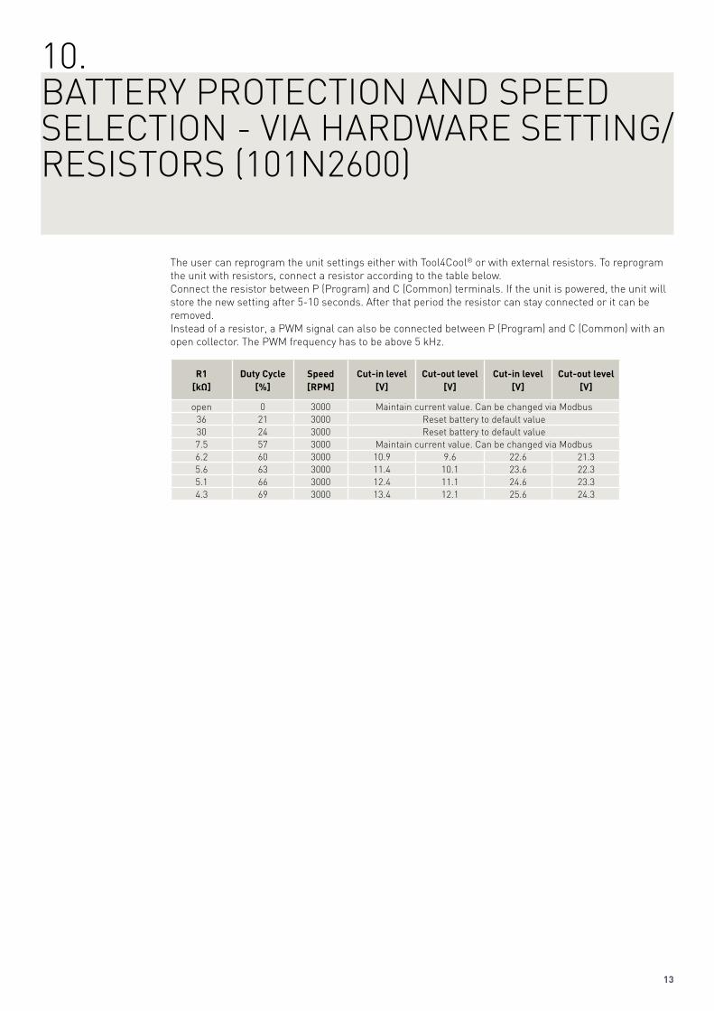
10. BATTERY PROTECTION AND SPEEDSELECTION - VIA HARDWARE SETTING/RESISTORS (101N2600)
The user can reprogram the unit settings either with Tool4Cool® or with external resistors. To reprogram the unit with resistors, connect a resistor according to the table below.Connect the resistor between P (Program) and C (Common) terminals. If the unit is powered, the unit will store the new setting after 5-10 seconds. After that period the resistor can stay connected or it can be removed.Instead of a resistor, a PWM signal can also be connected between P (Program) and C (Common) with an open collector. The PWM frequency has to be above 5 kHz.
R1[kΩ]
Duty Cycle[%]
Speed[RPM]
Cut-in level[V]
Cut-out level[V]
Cut-in level[V]
Cut-out level[V]
open 0 3000 Maintain current value. Can be changed via Modbus 36 21 3000 Reset battery to default value30 24 3000 Reset battery to default value7.5 57 3000 Maintain current value. Can be changed via Modbus 6.2 60 3000 10.9 9.6 22.6 21.35.6 63 3000 11.4 10.1 23.6 22.35.1 66 3000 12.4 11.1 24.6 23.34.3 69 3000 13.4 12.1 25.6 24.3
14
The speed of the condenser fan can be controlled in order to save energy, reduce noise and optimizethe fan operation.The fan is synchronized with the compressor operation. Start and stop delays can be set up as a function of the state of the parameter Thermostat. Furthermore, the fan can be set to run continuously (forced ON operation).Some fan defects including a missing fan can be detected,these defects can be displayed in the Error log.The speed of the fan can be controlled in the range from 40% to 100%.Enable detect missing fan parameter to allow ECU to detect missing fan from F and C terminals.
Settings
Name Default Max value Min value Step Unit
Requested fan speed
100 100 40 1 %
Fan start delay 0 240 0 1 Seconds
Fan stop delay 0 240 0 1 Seconds
Fan forced ON OFF ON OFF 1
Detect missing fan
OFF ON OFF 1
Measurements
Name Description Value Unit
Condenser fan speed Actual fan speed 0 - 100 %
11. CONDENSER FAN
15
Thermostat typeTwo types of thermostat can be used for temperature control.
Electronic thermostat (NTC sensor)The electronic thermostat provides active temperature control.A disconnected sensor error alarm (NTC sensor failure) is sent when the measured temperature is › +100ºCA short circuited sensor error alarm (NTC sensor failure) is sent when the measured temperature is ‹ -50ºCNTC sensor error will only be detected when the Thermostat is set to “NTC”. A NTC error is not detectable when the Thermostat input is operating in automatic thermostat selection mode. A NTC sensor is recommended for the whole application temperature range.
Mechanical thermostatA mechanical ON/OFF thermostat can be connected at terminals C & T.No detection of faulty thermostat is provided when an ON/OFF thermostat is used.
Automatic thermostat selectionThe Thermostat parameter displays the type of thermostat connected to the controller: either a mechanical thermostat or NTC temperature sensor.Note: A NTC sensor error is not detectable when the NTC sensor is operating in automatic thermostat selection mode. Select Electronic Thermostat instead, if this error must be detected. The temperature setpoint and hysteresis can be selected via Communication interface. At “Cut-out temperature” the (lower) switch-off temperature must be entered (e.g. 5°C). A “Difference” the hysteresis must be entered (e.g. 2°C). The compressor will then start, once the temperature raises above 7°C and would stop if the temperature would be below 5°C.With “Forced on” the user can set the compressor to run continuously even when the temperature is below cut-out.
Settings
Name Default Max value Min value Step Unit
Type Auto Auto Mechanical
Cut-out temperature
5 40 -40 1 Deg C
Cut-in Difference 2 15 1 1 Deg C
Forced on OFF ON OFF 1 Measurements
Name Description Value Unit
Cut in time Cut-in time will show the time for the last cooling period (thermostat cut-in period).
Cut-in time is reset at every start of cooling ON period
min
Thermostat temperature
Real time air temperature when a NTC sensor is used. When a mechanical thermostat is used, only
thermostat status ON or OFF is displayed
Deg C
12. THERMOSTAT
16
SETPOINT SELECTION during standalone operation (without Tool4Cool®) In order to utilize the integrated temperature control, connect a 10k potentiometer between S and C (R2). Via this potentiometer, a temperature setpoint between -20 and 10 deg C can be selected as per the table below. The potentiometer resistance adjusts the temperature setpoint around which the cut-in and cut-out occurs. It is defined as the average value between cut-in and cut-out.
The temperature setpoint will not change the cut-in difference, but only adjust the cut-out based on the temperature setpoint and the actual cut-in diff setting.
Cut-out = temperature setpoint – cut-in diff / 2 Settings
Set point R2 [ohm]
-20 0
-19 333
-18 667
-17 1000
-16 1333
-15 1667
-14 2000
-13 2333
-12 2667
-11 3000
-10 3333
-9 3667
-8 4000
-7 4333
-6 4667
-5 5000
-4 5333
-3 5667
-2 6000
-1 6333
0 6667
1 7000
2 7333
3 7667
4 8000
5 8333
6 8667
7 9000
8 9333
9 9667
10 10000
C
S
ExternalPotentionmeter
Electronic Unit101N2100101N2600
R2
Setpoint
17
Operation in ECO mode reduces energy consumption and noise by controlling the compressor speed as a function of temperature. ECO mode can only be selected when using an NTC temperature sensor.
The cooling capacity of the compressor can be varied by enabling the ECO-Speed function. When NTC temperature is below ECO temperature, the cooling capacity is reduced. Thus, the supercooling and superheating is reduced, which increases the coefficient of performance (COP). This enables a better energy classification, while the application still has the full cooling capacity above ECO temperature.
In ECO mode,
• when operating below ECO temperature, compressors run at the set ECO speed.• when operating above ECO temperature, the compressors run at Requested speed. Settings
Name Default Max value Min value Step Unit
ECO mode OFF ON OFF
ECO speed 2000 4000 2000 10 rpm
Measurements
Name Default Max value Min value Step Unit
ECO temperature 0.1 Deg C
Note: This feature is only available in electronic unit 101N2100.
13. ECO FUNCTION (101N2100)
ECO modeAuto calculation of ECO temp. & manual selection of
Temp.
Cut-in temp.
Diff / 2Diff / 2
Diff
Cut-out temp.
ECO temp. =Cut-out +(Diff/2)
Comp.speed
4000
3500
3000
2500
0
Requested speed Eco speed
“Eco speed”
2000
18
In order to prevent the compressor from short cycling, a min restart time is implemented. After timeout of the compressor restart time a new start of the compressor is permitted. If the system pressure is equalized very slowly in the specific system, increasing the restart time will help to reduce the back pressure and help to ease the starting condition.
Settings
Name Default Max value Min value Step Unit
Restart Delay 60 120 60 1 Seconds
14. COMPRESSOR SAFETY
19
Lost communicationIn a network system with custom designed interface modules acting as the master on the Modbus, it isdesirable to stop the compressor from running when communication to the master is lost. When "Set main switch to off when communication timeout occurs" is enabled, the Main-Switch will be set to off. The function will stop the compressor after a certain time, (Communication time out) when there is no contact to the master controller. The stop is realized through the Main Switch. The Main Switch will beset to OFF. It will remain OFF until the master controller sets it back to ON via the Modbus. The compressor will only be stopped due to lost communication if there has been a communication with the unit after power on. If there hasn’t been any communication with the electronic at all, it will run as a stand alone unit and will not stop due to missing communication.
Communication setting description Node number - Address of the electronic unit on the Modbus. It must be ensured that each address on the BUS is used only once.Bits per second - Is equivalent to the communication speed on the Modbus. All devices on one bus-line must share the same speed.Set main switch to off when communication time-out occurs - When enabled shall set Main Switch to off when communication time-out occurs.Communication time-out - Defines the duration of communication time-out.
Protection of settingsA coded privacy function protects customers’ settings from being read by third parties. The code must be verified by entering it twice. Settings
Name Default Max value Min value Step Unit
Node number 1 247 1 1
Bits per second 19200 19200 9600 9600 bps
Set main switch to off when
communication timeout occurs
0 1 0 1 0 = disabled 1 = enabled
Communication timeout
900 7200 15 1 seconds
Setting protection code & status
0 9999 0 1
15. COMMUNICATION
20
Secop labels on electronic units consist of a 2D Data Matrix Code area and a number of lines with information. The 2D Data Matrix Code is always built up with 62 characters containing information about type, code number, product version, product revision, unit ID, supplier, part number and text.
Text information on the label:Line 1: ID: PLYYWWssssss (unique number)Line 2: Date: YYWWLine 3: Ver.: VVLine 4: Text: text
Unit name Possible to fill in customer name for the unit when presented in PC software program Tool4cool®.
Measurements
Name Description
Vendor name Vendor name
Product code no. Secop product code number
Firmware version Controller software version
Unit ID Secop unit ID
Production date Secop production date
Serial no. Secop serial no.
16. PRODUCT INFORMATION
21
In order to have the possibility to change and set values in a custom designed interface module, a custom register is implemented. Change and interaction will be via communication interface (e.g. Tool4Cool® , a customer display or customer specific electronic). The parameters are visible even when in protected mode. Please consult Secop contact person for further information. Settings
Name Default Max value Min value Step Unit
Register 1 65535 65535 0 1
to
Register 10 65535 65535 0 1
17. CUSTOMER REGISTER
22
18. ERRORS IN ELECTRONIC UNIT
The purpose of the alarm function is to notify the user when there is an error in the system, in order to take measures to prevent damage on the refrigeration system. Measurements
Name Description
Actual error 0 = No error 1 = Battery protection failure 2 = Fan failure 3 = Motor failure 4 = Speed failure 5 = Thermal failure 6 = NTC failure 7 = Communication error
23
19. EVENT LOGGING
In order to assist in service and fault situations, an event log is implemented in ECU, the log is read out via Tool4Cool®. The log contains parameters and events when parameter changes and on Power up.
Each event contains the following information:• Time of occurrence related to compressor power up, with 1 sec as sample time• The sequence of occurrence (Event list reference)• Parameter/Event description• The value of the parameter• Number of occurrence (when no value is related to the parameter)• The value of the parameter which caused the failure (if connected to a parameter); it is possible to clear the event log via a clear function.
24
Electronic unit overheating protectionThe protection system ensures that the controller does not operate at extremely high temperatures, because under these conditions the quality of the soldered joints will be endangered. When the unit reaches 100 ºC(measured by PCB NTC) the system will shut down and an alarm error (Thermal failure) will be raised. After the temperature has dropped below 90ºC and the setting “Compressor restart delay” has elapsed, the compressor is restarted automatically.
Electronic unit under temperature protectionThe protection system ensures that the compressors, including the magnets in the motor, are not damaged by excessively low temperatures. When the unit reaches -10ºC on PCB the system will shut down and an alarm error (Thermal failure) will be raised.After the temperature has risen above -5ºC and the setting “Compressor restart delay” has elapsed, the compressor is restarted automatically (default 60 sec).
20. TEMPERATURE PROTECTION
Electronic Unit Under-Temperature Protection
-5°C
-10°C
Inverter temp.
Alarm state
Comp. state
(Restart delay)
ON
OFF
OFF
ON (Thermal failure)
PCB Hotspot Protection
100°C
90°C
PCB Hotspot temp.
(Restart delay)60-120 sec
Alarm state
Comp. stateON
OFF
OFF
ON (Thermal failure)
25
21. PARAMETERS
ParameterGroup
Parameter Description Default Max value
Min value
Step Unit Type
Main functions
Main switch
The compressor start and stop is realized through the Main Switch.0 = Off1 = On
1 1 0 1 Setting
Battery protection
Battery cut-out level
Current battery protection cut-out voltage level
0.1 volt Setting
Battery cut-in diff.
Current voltage difference between battery cut-in and cut-out
1.3 10 0.5 0.1 volt Setting
Cut-in level
Calculated value.Cut-in = Cut-out + Diff.
0.1 volt Measurement
Battery cut-out level - 12V
Battery protection cut-out voltage level for 12V
10.4 17 9.6 0.1 volt Setting
Battery cut-in diff. - 12V
Voltage difference between batterycut-in and cut-out for 12V
1.3 10 0.5 0.1 volt Setting
Battery cut-out level - 24V
Battery protection cut-out voltage level for 24V
21.3 27 19 0.1 volt Setting
Battery cut-in diff. - 24V
Voltage difference between battery cut-in and cut-out for 24V
1.3 10 0.5 0.1 volt Setting
Cut-out delay
To avoid stopping the motor due to a short, undervoltage event. It is desired to ignore the supply voltage for the time “Cut-out delay“, until Battery protection goes active
3 60 0 1 sec Setting
Solar mode *
Turn ON/Off Solar mode0 = Off1 = On
0 1 0 1 Setting
Supply voltage
0.1 volt Measurement
* Note: This feature is only available in electronic unit 101N2100.
26
ParameterGroup
Parameter Description Default Max value
Min value
Step Unit Type
Compressor
Defaultrequested speed *
Compressor speed and therefore capacity definition
4000 4000 2000 10 rpm Setting
Start delay The time that the compressor should wait after the thermostat is switched on.
4 240 2 1 sec Setting
Start speed
Start speed is fixed at 2500 rpm, to ensure reliable start performance.
2500 Readout
Start time Period of time for which the Start Speed should be effective before switching to Requested Speed.
30 600 30 1 sec Setting
Compressor speed
Real-time speed (+/-10%) 1 rpm Measurement
Compressor runtime
The Compressor Runtime shows the time for the last compressor running period.Compressor runtime is reset at every start of a compressor
1 min Measurement
Condenser fan
Requested fan speed
Fan speed 100 100 40 1 % Setting
Fan start delay
The time that the fan should wait after the thermostat is switched on.
0 240 0 1 sec Setting
Fan stop delay
The time that the fan should run after the thermostat is switched off.
0 240 0 1 sec Setting
Fan forced on
To run the fan continuously (forced ON operation) irrespective of thermostat state.0 = Disabled1 = Enabled
0 1 0 1 Setting
Detect missing fan
Detect whether fan is connected.0 = Disabled1 = Enabled
0 1 0 1 Setting
Condenser fan speed
Real-time fan speed % Measurement
* Note: This feature is only available in electronic unit 101N2100.
27
ParameterGroup
Parameter Description Default Max value
Min value
Step Unit Type
Thermostat
Type Detect mechanical or electronic sensor thermostat0 = Mechanical1 = Electronic (NTC)2 = Auto (Both NTC & Mechanical)
2 2 0 1 Setting
Cut-out Temperature
Compressor cuts out below cutout temperature
5 40 -40 1 °C Setting
Cut-in difference
2 15 1 1 °C Setting
Cut-in Temperature
1 °C Readout
Forced on Force thermostat operation to continuously on irrespective of actual thermostat state
0 1 0 1 Setting
ECO mode * Turns the ECO mode on and off
0 1 0 1 Setting
ECO speed * Speed applied when temperature falls below ECO temperature
2000 4000 2000 1 rpm Setting
ECO temperature *
Temperature where ECO speed is applied
Readout
Thermostat Thermostat state0 = Off1 = On
1 Measurement
Thermostat temperature
°C Measurement
Cut in time Cut-in time will show the time for the last cooling period (thermostat cut-in period).Cut-in time is reset at every start of cooling ON period.
1 min Measurement
Compressor safety
Restart delay The time that the unit should wait before attempting a restart, after an error has occured.
60 120 60 1 sec Setting
Communication
Node number Modbus address 1 247 1 1 Setting
Bits per second 19200 19200 9600 9600 bps Setting
Set main switch to off when communication timeout occurs
Enable/disable funtion "Set main switch to off when communication timeout occurs"0 = Disabled1 = Enabled
0 1 0 1 Setting
Communication timeout
Maximum duration of each communication attempt
900 7200 15 1 sec Setting
Settings protection code
Privacy function code must be entered twice
0 9999 0 Setting
Settings protection status
Read the status of unit-1 = Unlocked-2 = Locked-3 = Verify code
-1 -2 -1 1 Measurement
* Note: This feature is only available in electronic unit 101N2100.
28
ParameterGroup
Parameter Description Default Max value
Min value
Step Unit Type
Product information
Unit name The user’s own identification name for the unit can be entered here (optional)
COP (EN 12900 Household/CECOMAF) 12V DC, static cooling W/W
COP (ASHRAE LBP) 12V DC, static cooling W/W
30
23. PERFORMANCE DATA BD1.4F-FSD COMPRESSOR
rpm \ °C -30 -25 -23.3 -20 -15 -10 -5 0
3,000 0.40 0.74 0.83 1.01 1.28 1.56 1.86 2.19
rpm \ °C -30 -25 -23.3 -20 -15 -10 -5 0
3,000 0.30 0.58 0.66 0.81 1.02 1.25 1.49 1.75
rpm \ °C -30 -25 -23.3 -20 -15 -10 -5 0
3,000 1.30 1.73 1.88 2.16 2.57 2.98 3.37 3.76
rpm \ °C -30 -25 -23.3 -20 -15 -10 -5 0
3,000 15.7 22.6 24.8 28.8 34.5 39.6 44.4 48.7
Power consumption 12V DC, static cooling watt
Current consumption (for 24V applications the following must be halfed) A
rpm \ °C -30 -25 -23.3 -20 -15 -10 -5 0
3,000 4.7 13.2 16.4 23.3 35.2 49.4 66.0 85.4
Capacity (EN 12900 Household/CECOMAF) 12V DC, static cooling watt
rpm \ °C -30 -25 -23.3 -20 -15 -10 -5 0
3,000 6.4 16.8 20.8 29.2 44.0 61.5 82.2 106
Capacity (ASHRAE LBP) 12V DC, static cooling watt
COP (EN 12900 Household/CECOMAF) 12V DC, static cooling W/W
COP (ASHRAE LBP) 12V DC, static cooling W/W
31
24. DIMENSIONSBD1.4F-VSD/-FSD COMPRESSOR
Height mm A 96.25
B 91.25
B1 87.70
B2 38.50
Suction connector location/I.D. mm | angle C 6.2 | 15°
material | comment Cu-plated steel | Al cap
Process connector location/I.D. mm | angle D 6.2 | 25°
material | comment Cu-plated steel | Al cap
Discharge connector location/I.D. mm | angle E 5.0 | 15°
material | comment Cu-plated steel | Al cap
Connector tolerance I.D. mm ±0.09, on 5.0 +0.12/+0.20
Remarks
Produced by Secop | June 2013 DES.S.100.E1.02
Secop can accept no responsibility for possible errors in catalogues, brochures and other printed material. Secop reserves the right to alter its products without notice. This also applies to products already on order provided that such alterations can be made without subsequential changes being necessary in specifications already agreed. All trademarks in this material are property of the respective companies. Secop and the Secop logotype are trademarks of Secop GmbH. All rights reserved
BD1.4F–VSD/-HD – NEW MILESTONES IN MOBILE COOLINGThe new BD1.4F-VSD from Secop is 60% smaller than previous models and weighs in at only 2.3 kilograms. Perfect for 10-20 litre in-car/van/boat cabinets or portable boxes that need to fit into tight spaces without compromising storage space. Specially designed for maximum efficiency and reliability this powerhouse of a compressor makes it easier than ever to provide leading class mobile fridges. Enabling the variable speed function increases the sys-tem’s COP. Low energy consumption is beneficial for car/van/boat batteries – as well as the environment.The optimized, low noise motor ensures outstanding performance when you want to provide that extra degree of luxury on the move. The electronic thermostat provides an accurate temperature while the failure detection allows a prompt fault diagnosis. The computer interface makes it easier for customization via TOOL4COOL®. Cool beverages on demand make your journey so much more of an excellent experience.The Heavy Duty version BD1.4F-VSD-HD can handle extreme vibrations.
1958Start up productionof PW compressors.
1972Introduction FRcompressors.
1993Start of production with natural refrigerant R600a (Isobutane)
Production facility in Crnomelj, Slovenia founded.
2008Production facilityin Wuqing, Chinafounded.
1970Introduction of SC compressors.The birth of a stand-ard setting platform in the light commer-cial market.