Read this document and the documents listed in the additional resources section about installation, configuration, and operation of this equipment before you install, configure, operate, or maintain this product. Users are required to familiarize themselves with installation and wiring instructions in addition to requirements of all applicable codes, laws, and standards.
Activities including installation, adjustments, putting into service, use, assembly, disassembly, and maintenance are required to be carried out by suitably trained personnel in accordance with applicable code of practice.
If this equipment is used in a manner not specified by the manufacturer, the protection provided by the equipment may be impaired.
In no event will Rockwell Automation, Inc. be responsible or liable for indirect or consequential damages resulting from the use or application of this equipment.
The examples and diagrams in this manual are included solely for illustrative purposes. Because of the many variables and requirements associated with any particular installation, Rockwell Automation, Inc. cannot assume responsibility or liability for actual use based on the examples and diagrams.
No patent liability is assumed by Rockwell Automation, Inc. with respect to use of information, circuits, equipment, or software described in this manual.
Reproduction of the contents of this manual, in whole or in part, without written permission of Rockwell Automation, Inc., is prohibited
Throughout this manual, when necessary, we use notes to make you aware of safety considerations.
Labels may also be on or inside the equipment to provide specific precautions.
WARNING: Identifies information about practices or circumstances that can cause an explosion in a hazardous environment, which may lead to personal injury or death, property damage, or economic loss.
ATTENTION: Identifies information about practices or circumstances that can lead to personal injury or death, property damage, or economic loss. Attentions help you identify a hazard, avoid a hazard, and recognize the consequence.
IMPORTANT Identifies information that is critical for successful application and understanding of the product.
SHOCK HAZARD: Labels may be on or inside the equipment, for example, a drive or motor, to alert people that dangerous voltage may be present.
BURN HAZARD: Labels may be on or inside the equipment, for example, a drive or motor, to alert people that surfaces may reach dangerous temperatures.
ARC FLASH HAZARD: Labels may be on or inside the equipment, for example, a motor control center, to alert people to potential Arc Flash. Arc Flash will cause severe injury or death. Wear proper Personal Protective Equipment (PPE). Follow ALL Regulatory requirements for safe work practices and for Personal Protective Equipment (PPE).
Rockwell Automation Publication 1756-UM004A-EN-P - March 2019 3
Table of Contents
Notes:
4 Rockwell Automation Publication 1756-UM004A-EN-P - March 2019
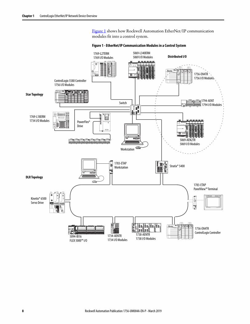
Preface
This manual describes how you can use ControlLogix® EtherNet/IP™ communication modules with a Logix 5000™ controller and communicate with various devices on the Ethernet/IP network.
Use this manual if you program applications that use EtherNet/IP networks with these Logix 5000 controllers:
Provides details about how to use EtherNet/IP communication modules with Logix 5000 controllers and communicate with other devices on the EtherNet/IP network.
EtherNet/IP Network Devices User Manual, publication ENET-UM006
Describes how to install, configure, and operate the Compact 5000™ I/O EtherNet/IP adapters.
Provides information about how to complete these tasks with EtherNet/IP communication modules in a Logix 5000 control system:• Install the module• Configure initial application setup• Troubleshoot application anomalies that are
related to EtherNet/IP communication module use
EtherNet/IP Media Planning and Installation ManualThis manual is available from the Open DeviceNet® Vendor Association (ODVA) at: http://www.odva.org.
Provides details about how to install, configure, and maintain linear and Device Level Ring (DLR) networks by using Rockwell Automation EtherNet/IP devices that are equipped with embedded switch technology.
Provides details about how to install, configure, and maintain linear and Device Level Ring (DLR) networks by using Rockwell Automation EtherNet/IP devices that are equipped with embedded switch technology.
EtherNet/IP Device Level Ring Application Technique, publication ENET-AT007
Describes DLR network operation, topologies, configuration considerations, and diagnostic methods.
Rockwell Automation Publication 1756-UM004A-EN-P - March 2019 5
You can view or download publications athttp://www.rockwellautomation.com/global/literature-library/overview.page. To order paper copies of technical documentation, contact your local Allen-Bradley distributor or Rockwell Automation sales representative.
Describes the socket interface that you can use to program MSG instructions to communicate between a Logix5000 controller via an EtherNet/IP module and Ethernet devices that do not support the EtherNet/IP application protocol, such as bar code scanners, RFID readers, or other standard Ethernet devices.
Overview EtherNet/IP™ networks are communication networks that offer a comprehensive suite of messages and services for many automation applications.
This open network standard uses commonly available Ethernet communication products to support real-time I/O messaging, information exchange, and general messaging.
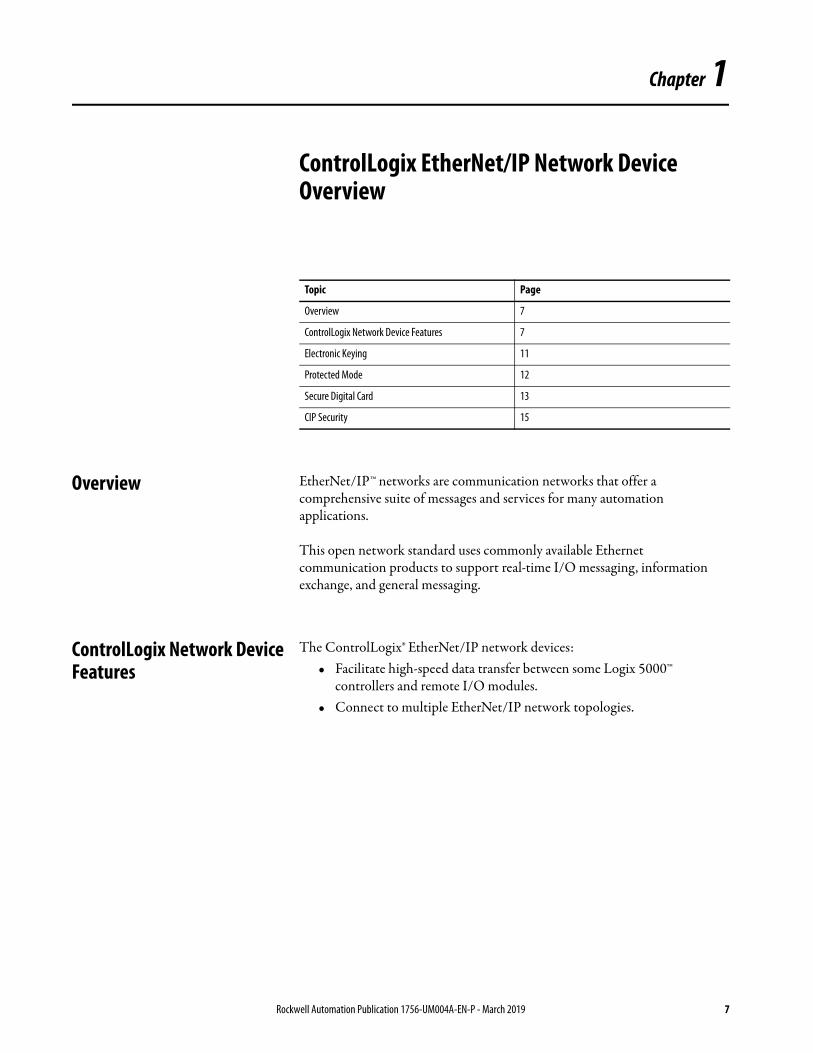
ControlLogix Network Device Features
The ControlLogix® EtherNet/IP network devices:• Facilitate high-speed data transfer between some Logix 5000™
controllers and remote I/O modules.• Connect to multiple EtherNet/IP network topologies.
Topic Page
Overview 7
ControlLogix Network Device Features 7
Electronic Keying 11
Protected Mode 12
Secure Digital Card 13
CIP Security 15
Rockwell Automation Publication 1756-UM004A-EN-P - March 2019 7
256+256 — • 50,000 without CIP Security• 25,000 with integrity• 15,000 with integrity and
confidentiality
• 3,700 without CIP Security
• 2,700 with integrity
• 1,700 with integrity and confidentiality
Yes
1756-EN4TRXT 512 1000 I/O528(2)
256+256 — • 50,000 without CIP Security• 25,000 with integrity• 15,000 with integrity and
confidentiality
• 3,700 without CIP Security
• 2,700 with integrity
• 1,700 with integrity and confidentiality
Yes
1756-EWEB 64 128(1) 128 + 128 — — 900 Yes(1) CIP connections can be used for all explicit or all implicit applications. For example, a 1756-ENBT module has a total of 128 CIP connections that can be used for any combination of connections.
(2) There are 1000 CIP I/O connections and 528 CIP messaging connections. (3) Total packet rate capacity = I/O Produced Tag, max + HMI/MSG, max. Packet rates vary depending on packet size. For more detailed specifications, see the EDS file for a specific catalog number.
10 Rockwell Automation Publication 1756-UM004A-EN-P - March 2019
Electronic Keying Electronic Keying reduces the possibility that you use the wrong device in a control system. It compares the device that is defined in your project to the installed device. If keying fails, a fault occurs. These attributes are compared.
The following Electronic Keying options are available.
Carefully consider the implications of each keying option when selecting one.
For more detailed information on Electronic Keying, see Electronic Keying in Logix 5000 Control Systems Application Technique, publication LOGIX-AT001.
Attribute Description
Vendor The device manufacturer.
Device Type The general type of the product, for example, digital I/O module.
Product Code The specific type of the product. The Product Code maps to a catalog number.
Major Revision A number that represents the functional capabilities of a device.
Minor Revision A number that represents behavior changes in the device.
Keying Option Description
Compatible Module
Lets the installed device accept the key of the device that is defined in the project when the installed device can emulate the defined device. With Compatible Module, you can typically replace a device with another device that has the following characteristics: • Same catalog number• Same or higher Major Revision• Minor Revision as follows:
– If the Major Revision is the same, the Minor Revision must be the same or higher.– If the Major Revision is higher, the Minor Revision can be any number.
Disable Keying Indicates that the keying attributes are not considered when attempting to communicate with a device. With Disable Keying, communication can occur with a device other than the type specified in the project.ATTENTION: Be cautious when using Disable Keying; if used incorrectly, this option can lead to personal injury or death, property damage, or economic loss. We strongly recommend that you do not use Disable Keying. If you use Disable Keying, you must take full responsibility for understanding whether the device being used can fulfill the functional requirements of the application.
Exact Match Indicates that all keying attributes must match to establish communication. If any attribute does not match precisely, communication with the device does not occur.
IMPORTANT Changing Electronic Keying parameters online interrupts connections to the device and any devices that are connected through the device. Connections from other controllers can also be broken.
If an I/O connection to a device is interrupted, the result can be a loss of data.
Rockwell Automation Publication 1756-UM004A-EN-P - March 2019 11
Protected Mode The1756-EN2T, 1756-EN2TP, 1756-EN2TR, and 1756-EN4TR support explicit protected mode.(1) When in this mode, the module does not allow any configuration changes.
Enabling Explicit Protected Mode
To enable the module in an “explicit protected mode state”, follow these steps.
1. Set the rotary switches to position ‘900’.
2. Power up the device, and wait for the display to scroll, “Protected Mode – Change Switch Settings”.
3. Power down the device.
4. Set the switches for normal operation.
5. Power up the device.
6. The device is now in Explicit Protected Mode.
Operation in Explicit Protected Mode
While working in protected mode, the module rejects any CIP™ explicit messages that would change the configuration of the module. For example, you cannot change the IP address, speed, or duplex settings when the module had Explicit Protected Mode enabled.
Disabling Explicit Protected Mode
To disable the “explicit protected mode state”, follow these steps.
1. Set the rotary switches on position ‘000’.
2. Power up the device, and wait for the display to scroll, “Unprotected Mode – Change Switch Settings”.
3. Power down the device.
4. Set the switches for normal operation.
5. Power up the device.
6. The device is now in Unprotected Mode.
(1) Versions 11.001 and later.
12 Rockwell Automation Publication 1756-UM004A-EN-P - March 2019
The 1756-EN4TR EtherNet/IP Bridge supports the use of a Secure Digital (SD) card to store configuration data, for example, the IP address or network communication rate for each port.
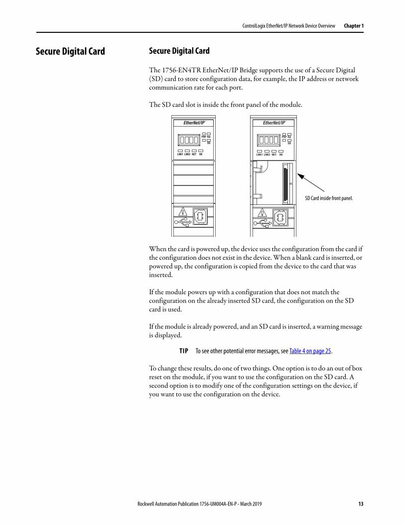
The SD card slot is inside the front panel of the module.
When the card is powered up, the device uses the configuration from the card if the configuration does not exist in the device. When a blank card is inserted, or powered up, the configuration is copied from the device to the card that was inserted.
If the module powers up with a configuration that does not match the configuration on the already inserted SD card, the configuration on the SD card is used.
If the module is already powered, and an SD card is inserted, a warning message is displayed.
To change these results, do one of two things. One option is to do an out of box reset on the module, if you want to use the configuration on the SD card. A second option is to modify one of the configuration settings on the device, if you want to use the configuration on the device.
TIP To see other potential error messages, see Table 4 on page 25.
SD Card inside front panel.
Rockwell Automation Publication 1756-UM004A-EN-P - March 2019 13
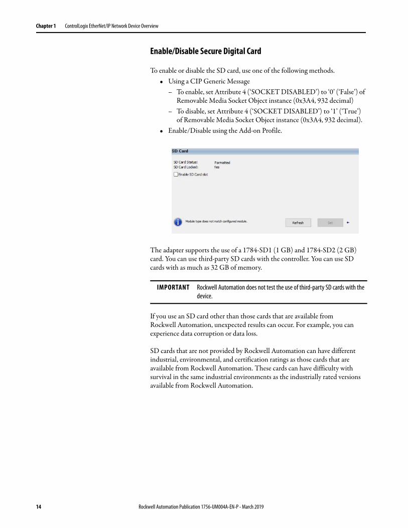
To enable or disable the SD card, use one of the following methods.• Using a CIP Generic Message
– To enable, set Attribute 4 (‘SOCKET DISABLED’) to ‘0’ (‘False’) of Removable Media Socket Object instance (0x3A4, 932 decimal)
– To disable, set Attribute 4 (‘SOCKET DISABLED’) to ‘1’ (‘True’) of Removable Media Socket Object instance (0x3A4, 932 decimal).
• Enable/Disable using the Add-on Profile.
The adapter supports the use of a 1784-SD1 (1 GB) and 1784-SD2 (2 GB) card. You can use third-party SD cards with the controller. You can use SD cards with as much as 32 GB of memory.
If you use an SD card other than those cards that are available from Rockwell Automation, unexpected results can occur. For example, you can experience data corruption or data loss.
SD cards that are not provided by Rockwell Automation can have different industrial, environmental, and certification ratings as those cards that are available from Rockwell Automation. These cards can have difficulty with survival in the same industrial environments as the industrially rated versions available from Rockwell Automation.
IMPORTANT Rockwell Automation does not test the use of third-party SD cards with the device.
14 Rockwell Automation Publication 1756-UM004A-EN-P - March 2019
CIP Security CIP Security™ is a standard, open-source communication method that helps to provide a secure data transport across an EtherNet/IP network.
The secure data transport is used between certain connected devices to help protect the devices from threats posed by unauthorized users with malicious intent.
CIP Security uses encryption to secure communication on an EtherNet/IP network, resulting in greater data integrity and confidentiality.
Rockwell Automation uses the following products to implement CIP Security:• FactoryTalk® Policy Manager • FactoryTalk Linx• Studio 5000® Design Environment• CIP Security-enabled Rockwell Automation® products, for example, the
product described in this publication(1)
For more information on CIP Security, including which products support CIP Security, see the CIP Security Application Technique, publication SECURE-AT001.
(1) In this document, CIP Security is applicable to 1756-EN4TR, 1756-ENRTRK, and 1756-EN4TRXT modules.
Rockwell Automation Publication 1756-UM004A-EN-P - March 2019 15
16 Rockwell Automation Publication 1756-UM004A-EN-P - March 2019
Chapter 2
Connect to the EtherNet/IP Network
EtherNet/IP™ networks are communication networks that offer a comprehensive suite of messages and services for many automation applications.
The following are examples of applications that use EtherNet/IP networks:• Real-Time Control• Time Synchronization• Motion
This open network standard uses commonly available Ethernet communication products to support real-time I/O messaging, information exchange, and general messaging.
EtherNet/IP networks also support CIP Safety™, which makes the simultaneous transmission of safety and standard control data and diagnostics information over a common network possible.
Topic Page
Set the IP Address 18
Set the IP Address with Rotary Switches 18
Other Methods to Set the IP Address 19
Reset the Module IP Address to Factory Default Value 19
Rockwell Automation Publication 1756-UM004A-EN-P - March 2019 17
Chapter 2 Connect to the EtherNet/IP Network
Set the IP Address The following conditions are required to set the IP address.
Requirements
To set the IP address, have the following:• EtherNet/IP or USB drivers that are installed on the programming
workstation• MAC ID from the device, which is on the label on the side of the device• Recommended IP address for the device
Set the IP Address with Rotary Switches
This graphic shows the rotary switches on a 1756 EtherNet/IP communication module. The three rotary switches at the bottom of the module, labeled X, Y, and Z, can be used for setting the IP address. The rotary switch in the upper left corner of the module is reserved for future configuration.
At powerup, the module reads the rotary switches to determine if they are set to a valid number for the last portion of the IP address. Valid numbers range from 001…254.
32794 M
18 Rockwell Automation Publication 1756-UM004A-EN-P - March 2019
Connect to the EtherNet/IP Network Chapter 2
If the settings are a valid number, these conditions result:• IP address = 192.168.1.xxx (where xxx represents the switch settings)• Subnet mask = 255.255.255.0• Gateway address = 0.0.0.0
• The module does not have a host name that is assigned to it, nor does it use any Domain Name System
We recommend that you set the rotary switches to a valid number before installing the module.
If the rotary switches are not set to a valid number, the module attempts to use the BOOTP/DHCP server to set the IP address.
Other Methods to Set the IP Address
The 1756-EN4TR module supports the following additional methods to change the IP address:
• BOOTP/DHCP utility• RSLinx® Classic software• Using Secure Digital Card• For more information on how to use these methods, see EtherNet/IP
Reset the Module IP Address to Factory Default Value
You can reset the configuration of the module to its factory default value with the following methods:
• If the module has rotary switches, set the switches to 888 and cycle power.
TIP Some modules now provide a gateway address of 192.168.1.1 when the network address is set with rotary switches.
IMPORTANT For more information on how to use the BOOTP/DHCP server to set the IP address, see EtherNet/IP Network Configuration Manual, publication ENET-UM006
Rockwell Automation Publication 1756-UM004A-EN-P - March 2019 19
Network Status Indicator (NET)Link Status Indicators (LINK)
Rockwell Automation Publication 1756-UM004A-EN-P - March 2019 21
Appendix A ControlLogix Network Device Status Indicators
Figure 4 - 1756-EN2TP (Dual-port Module)
Figure 5 - 1756-EN2TSC (Single-port Module)
Figure 6 - 1756-EN4TR (Dual-port Module)(1)
(1) Parallel Redundant Protocol and Redundant Adapter features are not available in the initial release. Check theProduct Compatibility and Download Center (PCDC) to see if it is available in your firmware revision.
32730
1756-EN2TP
Link Status Indicators (LINK)
OK Status Indicator
Network Status Indicator (NET)
Module Status Display
VPN
Network Status Indicator (NET)
OK Status Indicator
Module Status Display
Link Status Indicator (LINK)
Link Status Indicators (LINK)
Network Status Indicator (NET)
OK Status Indicator
Module Status DisplayParallel Redundant Protocol Status Indicator
Redundant Adapter Status IndicatorSD Card Status Indicator
22 Rockwell Automation Publication 1756-UM004A-EN-P - March 2019
ControlLogix Network Device Status Indicators Appendix A
Figure 7 - 1756-ENBT (Single-port Module)
Figure 8 - 1756-EWEB (Single-port Module)
VPN
Module Status Display
OK Status Indicator
Network Status Indicator (NET)Link Status Indicator (LINK)
Link Status Indicator (LINK)
Network Status Indicator (NET)
OK Status Indicator
Module Status Display
Rockwell Automation Publication 1756-UM004A-EN-P - March 2019 23
Appendix A ControlLogix Network Device Status Indicators
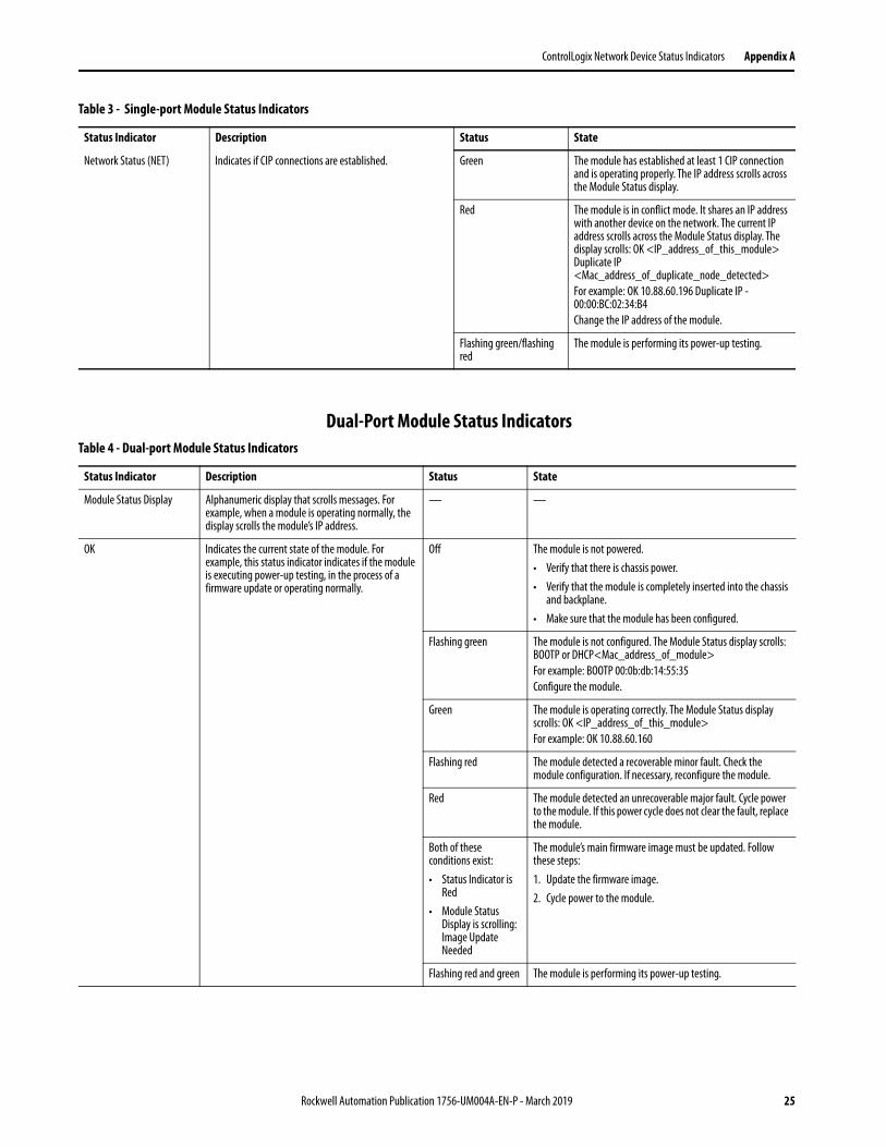
Single-Port Module Status IndicatorsTable 3 - Single-port Module Status Indicators
Status Indicator Description Status State
Module Status Display Alphanumeric display that scrolls messages. For example, when a module is operating normally, the display scrolls the module’s IP address.
— —
Link Status (LINK) Indicates the current state of the module regarding transmission of data on the EtherNet/IP™ network.
Off One of these conditions exists:• The module is not powered.
– Verify that there is chassis power.– Verify that the module is completely inserted
into the chassis and backplane.– Make sure that the module has been
configured.• No link exists on the port.
Flashing green Activity exists on the port.
Green The port is active, but not receiving traffic.
OK Status (OK) Indicates the current state of the module. For example, this status indicator indicates if the module is executing power-up testing, in the process of a firmware update or operating normally.
Off The module is not powered.• Verify that there is chassis power.• Verify that the module is completely inserted into
the chassis and backplane.• Make sure that the module has been configured.
Flashing green The module is not configured. The Module Status display scrolls: BOOTP or DHCP<Mac_address_of_module>For example: BOOTP 00:0b:db:14:55:35Configure the module.
Green The module is operating correctly. The IP address scrolls across the Module Status display.
Flashing red The module detected a recoverable minor fault. Check the module configuration. If necessary, reconfigure the module.
Red The module detected an unrecoverable major fault. Cycle power to the module. If this power cycle does not clear the fault, replace the module.
Network Status (NET) Indicates if CIP™ connections are established. Off One of these conditions exists:• The module is not powered.
– Verify that there is chassis power.– Verify that the module is completely inserted
into the chassis and backplane.– Make sure that the module has been
configured.• The module is powered but does not have an IP
address. Assign an IP address to the module.
Flashing green The controller has an IP address and one of these conditions exists:• The module has not established any CIP
connections.If connections are configured for this module, check the connection originator for the connection error code.
• All connections to the device have timed out or been closed.
24 Rockwell Automation Publication 1756-UM004A-EN-P - March 2019
ControlLogix Network Device Status Indicators Appendix A
Dual-Port Module Status Indicators
Network Status (NET) Indicates if CIP connections are established. Green The module has established at least 1 CIP connection and is operating properly. The IP address scrolls across the Module Status display.
Red The module is in conflict mode. It shares an IP address with another device on the network. The current IP address scrolls across the Module Status display. The display scrolls: OK <IP_address_of_this_module> Duplicate IP <Mac_address_of_duplicate_node_detected>For example: OK 10.88.60.196 Duplicate IP - 00:00:BC:02:34:B4Change the IP address of the module.
Flashing green/flashing red
The module is performing its power-up testing.
Table 3 - Single-port Module Status Indicators
Status Indicator Description Status State
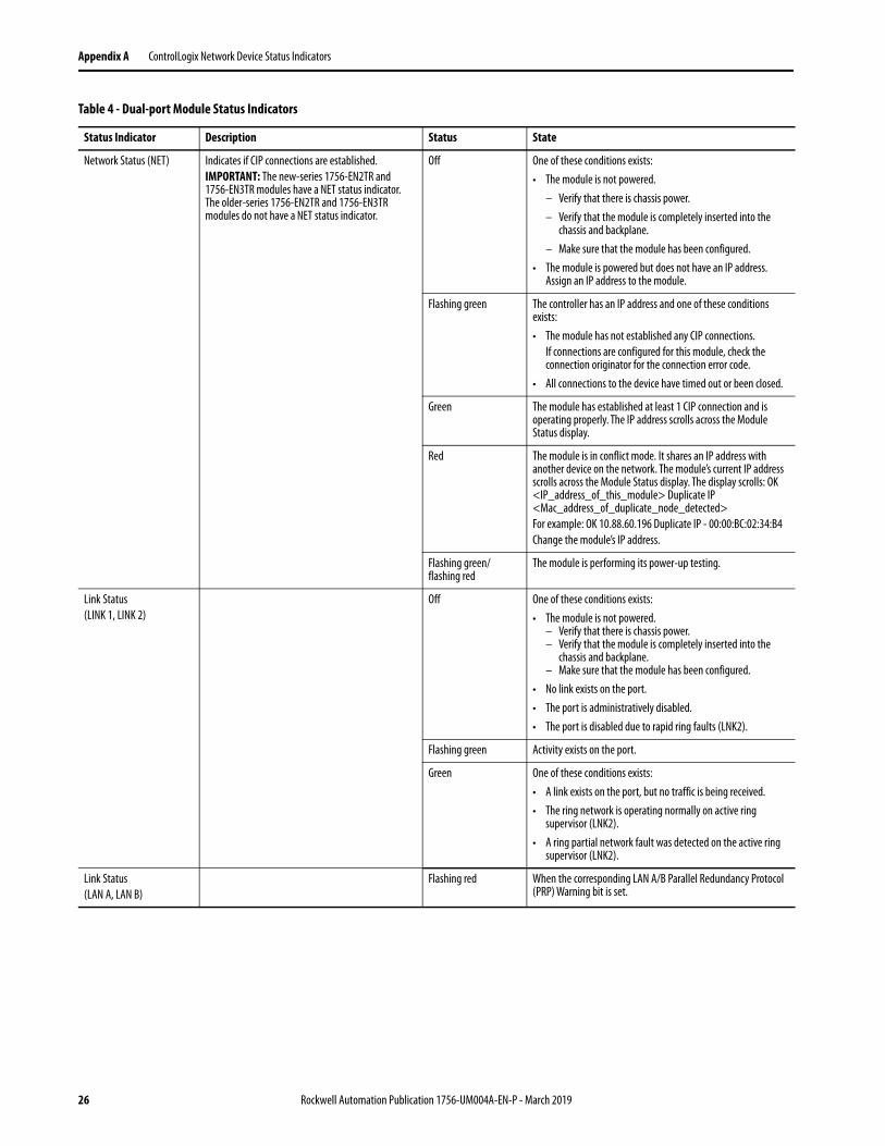
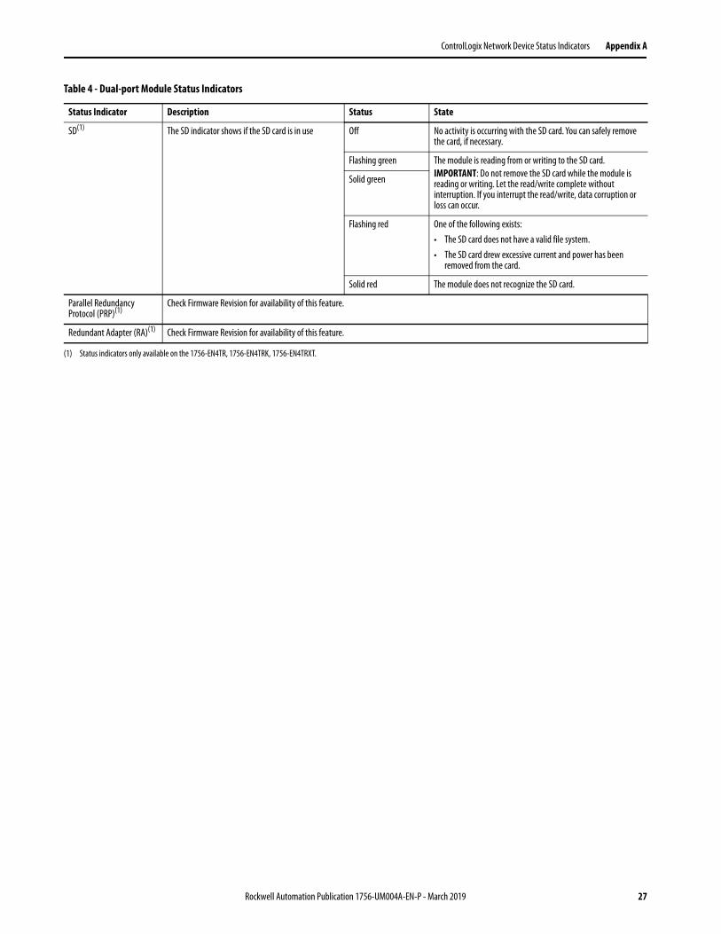
Table 4 - Dual-port Module Status Indicators
Status Indicator Description Status State
Module Status Display Alphanumeric display that scrolls messages. For example, when a module is operating normally, the display scrolls the module’s IP address.
— —
OK Indicates the current state of the module. For example, this status indicator indicates if the module is executing power-up testing, in the process of a firmware update or operating normally.
Off The module is not powered.• Verify that there is chassis power.• Verify that the module is completely inserted into the chassis
and backplane.• Make sure that the module has been configured.
Flashing green The module is not configured. The Module Status display scrolls: BOOTP or DHCP<Mac_address_of_module>For example: BOOTP 00:0b:db:14:55:35Configure the module.
Green The module is operating correctly. The Module Status display scrolls: OK <IP_address_of_this_module>For example: OK 10.88.60.160
Flashing red The module detected a recoverable minor fault. Check the module configuration. If necessary, reconfigure the module.
Red The module detected an unrecoverable major fault. Cycle power to the module. If this power cycle does not clear the fault, replace the module.
Both of these conditions exist:• Status Indicator is
Red• Module Status
Display is scrolling: Image Update Needed
The module’s main firmware image must be updated. Follow these steps:1. Update the firmware image.2. Cycle power to the module.
Flashing red and green The module is performing its power-up testing.
Rockwell Automation Publication 1756-UM004A-EN-P - March 2019 25
Appendix A ControlLogix Network Device Status Indicators
Network Status (NET) Indicates if CIP connections are established.IMPORTANT: The new-series 1756-EN2TR and1756-EN3TR modules have a NET status indicator.The older-series 1756-EN2TR and 1756-EN3TR modules do not have a NET status indicator.
Off One of these conditions exists:• The module is not powered.
– Verify that there is chassis power.– Verify that the module is completely inserted into the
chassis and backplane.– Make sure that the module has been configured.
• The module is powered but does not have an IP address. Assign an IP address to the module.
Flashing green The controller has an IP address and one of these conditions exists:• The module has not established any CIP connections.
If connections are configured for this module, check the connection originator for the connection error code.
• All connections to the device have timed out or been closed.
Green The module has established at least 1 CIP connection and is operating properly. The IP address scrolls across the Module Status display.
Red The module is in conflict mode. It shares an IP address with another device on the network. The module’s current IP address scrolls across the Module Status display. The display scrolls: OK <IP_address_of_this_module> Duplicate IP <Mac_address_of_duplicate_node_detected>For example: OK 10.88.60.196 Duplicate IP - 00:00:BC:02:34:B4Change the module’s IP address.
Flashing green/flashing red
The module is performing its power-up testing.
Link Status (LINK 1, LINK 2)
Off One of these conditions exists:• The module is not powered.
– Verify that there is chassis power.– Verify that the module is completely inserted into the
chassis and backplane.– Make sure that the module has been configured.
• No link exists on the port.• The port is administratively disabled.• The port is disabled due to rapid ring faults (LNK2).
Flashing green Activity exists on the port.
Green One of these conditions exists:• A link exists on the port, but no traffic is being received.• The ring network is operating normally on active ring
supervisor (LNK2).• A ring partial network fault was detected on the active ring
supervisor (LNK2).
Link Status(LAN A, LAN B)
Flashing red When the corresponding LAN A/B Parallel Redundancy Protocol (PRP) Warning bit is set.
Table 4 - Dual-port Module Status Indicators
Status Indicator Description Status State
26 Rockwell Automation Publication 1756-UM004A-EN-P - March 2019
ControlLogix Network Device Status Indicators Appendix A
SD(1) The SD indicator shows if the SD card is in use Off No activity is occurring with the SD card. You can safely remove the card, if necessary.
Flashing green The module is reading from or writing to the SD card.IMPORTANT: Do not remove the SD card while the module is reading or writing. Let the read/write complete without interruption. If you interrupt the read/write, data corruption or loss can occur.
Solid green
Flashing red One of the following exists:• The SD card does not have a valid file system.• The SD card drew excessive current and power has been
removed from the card.
Solid red The module does not recognize the SD card.
Parallel Redundancy Protocol (PRP)(1)
Check Firmware Revision for availability of this feature.
Redundant Adapter (RA)(1) Check Firmware Revision for availability of this feature.
(1) Status indicators only available on the 1756-EN4TR, 1756-EN4TRK, 1756-EN4TRXT.
Table 4 - Dual-port Module Status Indicators
Status Indicator Description Status State
Rockwell Automation Publication 1756-UM004A-EN-P - March 2019 27
Appendix A ControlLogix Network Device Status Indicators
Notes:
28 Rockwell Automation Publication 1756-UM004A-EN-P - March 2019
Index
Aadditional resources 5
BBOOTP/DHCP utility 19
CCIP security 15compatible modules 11control system 8conventions 5
Ddevice type 11dual-port module 25
Eelectronic keying 11
changing parameters 11disable keying 11
EtherNet/IP 7communication modules 9connect to network 17control system 8
EtherNet/IP networkmodule features 10specifications 10
IIP Address
factory default 19requirements 18rotary switches 18set the IP address 18
Rockwell Automation SupportUse the following resources to access support information.
Documentation FeedbackYour comments will help us serve your documentation needs better. If you have any suggestions on how to improve this document, complete the How Are We Doing? form at http://literature.rockwellautomation.com/idc/groups/literature/documents/du/ra-du002_-en-e.pdf.
Technical Support Center Knowledgebase Articles, How-to Videos, FAQs, Chat, User Forums, and Product Notification Updates. https://rockwellautomation.custhelp.com/
Local Technical Support Phone Numbers Locate the phone number for your country. http://www.rockwellautomation.com/global/support/get-support-now.page
Direct Dial Codes Find the Direct Dial Code for your product. Use the code to route your call directly to a technical support engineer. http://www.rockwellautomation.com/global/support/direct-dial.page
Literature Library Installation Instructions, Manuals, Brochures, and Technical Data. http://www.rockwellautomation.com/global/literature-library/overview.page
Product Compatibility and Download Center (PCDC)
Get help determining how products interact, check features and capabilities, and find associated firmware. http://www.rockwellautomation.com/global/support/pcdc.page
.
Rockwell Otomasyon Ticaret A.Ş., Kar Plaza İş Merkezi E Blok Kat:6 34752 İçerenköy, İstanbul, Tel: +90 (216) 5698400
Rockwell Automation maintains current product environmental information on its website at http://www.rockwellautomation.com/rockwellautomation/about-us/sustainability-ethics/product-environmental-compliance.page.
Allen-Bradley, Compact 5000, ControlFLASH Plus, CompactLogix, ControlLogix, FactoryTalk, FLEX 5000, Logix 5000, PanelView, PowerFlex, Rockwell Software, Rockwell Automation, and Stratix are trademarks of Rockwell Automation, Inc.
CIP, DeviceNet, and EtherNet/IP are trademarks of ODVA, Inc.
Trademarks not belonging to Rockwell Automation are property of their respective companies.