74
ControlNet Coax Media Planning and Installation Guide 1786-series Installation Instructions

ControlNet Coax Media Planning and Installation Guide1786-series
Installation Instructions

Important User Information Because of the variety of uses for the products described in this publication, those responsible for the application and use of these products must satisfy themselves that all necessary steps have been taken to assure that each application and use meets all performance and safety requirements, including any applicable laws, regulations, codes and standards. In no event will Allen-Bradley be responsible or liable for indirect or consequential damage resulting from the use or application of these products.
Any illustrations, charts, sample programs, and layout examples shown in this publication are intended solely for purposes of example. Since there are many variables and requirements associated with any particular installation, Allen-Bradley does not assume responsibility or liability (to include intellectual property liability) for actual use based upon the examples shown in this publication.
Allen-Bradley publication SGI-1.1, Safety Guidelines for the Application, Installation and Maintenance of Solid-State Control (available from your local Allen-Bradley office), describes some important differences between solid-state equipment and electromechanical devices that should be taken into consideration when applying products such as those described in this publication.
Reproduction of the contents of this copyrighted publication, in whole or part, without written permission of Rockwell Automation, is prohibited.
Throughout this publication, notes may be used to make you aware of safety considerations. The following annotations and their accompanying statements help you to identify a potential hazard, avoid a potential hazard, and recognize the consequences of a potential hazard:
Allen-Bradley is a trademark of Rockwell Automation
ATTENTION
!Identifies information about practices or circumstances that can lead to personal injury or death, property damage, or economic loss.
IMPORTANT Identifies information that is critical for successful application and understanding of the product.

Preface
What’s in This Chapter This manual describes the required components of a ControlNet™ Coax media system and how to plan for and install these required components.
Abbreviations and Symbols
Related Publications
For information about this topic: Read:
Understand the ControlNet Coax Media System Chapter 1
Plan a ControlNet Coax Media System Chapter 2
Install a ControlNet Coax Media System Chapter 3
Reference Mount dimensions (taps and universal mounting bracket)
Appendix A
Maintain the Cable Strip Tool Appendix B
IMPORTANT We assume that you understand the fundamentals of electronics and electrical codes. If you do not, you should not attempt the procedures described in this manual.
This Means
PVC cable polyvinyl chloride cable
FEP cable fluorinated ethylene propylene cable
PLC processor Allen-Bradley programmable logic controller
network continues
Publication: Publication Number:
ControlNet Cable System Component List AG-2.2
Industrial Automation Wiring and Grounding Guidelines 1770-4.1
1 Publication CNET-IN002A-EN-P - December 2001

2
Common Techniques Used in This Manual
The following conventions are used throughout this manual:
• bulleted lists provide information, not procedural steps
• numbered lists provide sequential step
Rockwell Automation Support
Rockwell Automation offers support services worldwide, with over 75 sales/support offices, 512 authorized distributors, and 260 authorized systems integrators located throughout the United States alone, plus Rockwell Automation representatives in every major country in the world.
Local Product Support
Contact your local Rockwell Automation representative for:
• sales and order support
• product technical training
• warranty support
• support service agreements
Technical Product Assistance
If you need to contact Rockwell Automation for technical assistance, use Pre-Sales e-mail at [email protected]
TIP This symbol identifies helpful tips.
Publication CNET-IN002A-EN-P - December 2001

3
Obtain Technical Product Support
If you need to contact Rockwell Automation for technical assistance, try one of the following methods:
• Call your local Rockwell Automation representative
• ControlNet Post-sales Technical Support, 1.440.646.5800
• Web Links: http://www.ab.com — as a registered member, go to http://www.ab.com/mem/technotes/techmain.html
Your Questions or Comments about This Manual
If you find a problem with this manual, please notify us of it on the enclosed “How are We Doing” form (at the back of this manual).
If you have any suggestions about how we can make this manual more useful to you, please contact us at the following address:
Rockwell AutomationControl and Information GroupTechnical Communications1 Allen-Bradley DriveMayfield Heights OH 44124-6118
email: [email protected]
Publication CNET-IN002A-EN-P - December 2001

4
Notes:
Publication CNET-IN002A-EN-P - December 2001

Table of Contents
Important User Information . . . . . . . . . . . . . . . . . . . . . . . . . . 2
PrefaceWhat’s in This Chapter . . . . . . . . . . . . . . . . . . . . . . . . . . . . . 1Abbreviations and Symbols . . . . . . . . . . . . . . . . . . . . . . . . . . 1Related Publications . . . . . . . . . . . . . . . . . . . . . . . . . . . . . . . 1Common Techniques Used in This Manual. . . . . . . . . . . . . . . 2Rockwell Automation Support . . . . . . . . . . . . . . . . . . . . . . . 2
Local Product Support . . . . . . . . . . . . . . . . . . . . . . . . . . . 2Technical Product Assistance . . . . . . . . . . . . . . . . . . . . . . 2Obtain Technical Product Support . . . . . . . . . . . . . . . . . . 3Your Questions or Comments about This Manual . . . . . . . 3
Chapter 1Overview of The ControlNet CoaxMedia System
What’s in This Chapter . . . . . . . . . . . . . . . . . . . . . . . . . . . 1-1Understand the ControlNet Cable System . . . . . . . . . . . . . . 1-1Understand the ControlNet Components . . . . . . . . . . . . . . 1-2
Nodes . . . . . . . . . . . . . . . . . . . . . . . . . . . . . . . . . . . . . 1-3Taps . . . . . . . . . . . . . . . . . . . . . . . . . . . . . . . . . . . . . . 1-3Trunk Cable . . . . . . . . . . . . . . . . . . . . . . . . . . . . . . . . 1-4Cable Connectors. . . . . . . . . . . . . . . . . . . . . . . . . . . . . 1-4Segments. . . . . . . . . . . . . . . . . . . . . . . . . . . . . . . . . . . 1-5Repeaters . . . . . . . . . . . . . . . . . . . . . . . . . . . . . . . . . . 1-5Links . . . . . . . . . . . . . . . . . . . . . . . . . . . . . . . . . . . . . . 1-6Bridge . . . . . . . . . . . . . . . . . . . . . . . . . . . . . . . . . . . . . 1-6Network . . . . . . . . . . . . . . . . . . . . . . . . . . . . . . . . . . . 1-7
What’s Next . . . . . . . . . . . . . . . . . . . . . . . . . . . . . . . . . . . 1-7
Chapter 2Plan a ControlNet Coax Media System
What’s in This Chapter . . . . . . . . . . . . . . . . . . . . . . . . . . . 2-1Determine the Number of Taps You Need . . . . . . . . . . . . . 2-1Connect Program Devices . . . . . . . . . . . . . . . . . . . . . . . . 2-3Determine What Type of Cable You Need . . . . . . . . . . . . . 2-4Determine Trunk Cable Section Lengths. . . . . . . . . . . . . . . 2-5Determine How Many Terminators You Need . . . . . . . . . . 2-7Determine if You Need Repeaters . . . . . . . . . . . . . . . . . . . 2-7
Configure Your Link With Repeaters . . . . . . . . . . . . . . . 2-8Determine What Type of Connectors You Need . . . . . . . . . 2-10Using Redundant Media (Optional) . . . . . . . . . . . . . . . . . . 2-11Using IP67 Media . . . . . . . . . . . . . . . . . . . . . . . . . . . . . . . 2-15Application Considerations . . . . . . . . . . . . . . . . . . . . . . . . 2-15
General Wring Guidelines . . . . . . . . . . . . . . . . . . . . . . 2-16Order Components . . . . . . . . . . . . . . . . . . . . . . . . . . . . . . 2-18
Create a General Plan . . . . . . . . . . . . . . . . . . . . . . . . . 2-18Plan Your Segments. . . . . . . . . . . . . . . . . . . . . . . . . . . 2-18
i Publication CNET-IN002A-EN-P - December 2001

Table of Contents ii
Order Parts . . . . . . . . . . . . . . . . . . . . . . . . . . . . . . . . . 2-20What’s Next . . . . . . . . . . . . . . . . . . . . . . . . . . . . . . . . . . . 2-20
Chapter 3Install a ControlNet Coax Media System
What’s in This Chapter . . . . . . . . . . . . . . . . . . . . . . . . . . . 3-1Install the Trunk Cable . . . . . . . . . . . . . . . . . . . . . . . . . . . 3-2
Wire the External to Enclosures . . . . . . . . . . . . . . . . . . 3-2Wire Inside Enclosures. . . . . . . . . . . . . . . . . . . . . . . . . 3-2
Mount the Taps. . . . . . . . . . . . . . . . . . . . . . . . . . . . . . . . . 3-2Select Where To Mount The Taps. . . . . . . . . . . . . . . . . 3-2Mount the Taps . . . . . . . . . . . . . . . . . . . . . . . . . . . . . . 3-3
Install a Repeater Adapter . . . . . . . . . . . . . . . . . . . . . . . . . 3-5Install Cable Connectors . . . . . . . . . . . . . . . . . . . . . . . . . . 3-6Collect Your Tools . . . . . . . . . . . . . . . . . . . . . . . . . . . . . . 3-6
Locally Available Tools. . . . . . . . . . . . . . . . . . . . . . . . . 3-7Calibrate the Cutting Blades. . . . . . . . . . . . . . . . . . . . . . . . 3-7Strip the Cable . . . . . . . . . . . . . . . . . . . . . . . . . . . . . . . . . 3-9Attach the Connectors to the Cable . . . . . . . . . . . . . . . . . . 3-14Test for Electrical Shorts and Continuity . . . . . . . . . . . . . . . 3-18Connect Cable Sections . . . . . . . . . . . . . . . . . . . . . . . . . . . 3-19Terminate Segments . . . . . . . . . . . . . . . . . . . . . . . . . . . . . 3-20Connect Devices . . . . . . . . . . . . . . . . . . . . . . . . . . . . . . . . 3-21
Connect Programming Terminals Through the NAP. . . . 3-21Connect the Repeater to a ControlNet Link . . . . . . . . . . 3-22
Appendix AMounting Dimensions What’s in This Appendix . . . . . . . . . . . . . . . . . . . . . . . . . . A-1
Taps . . . . . . . . . . . . . . . . . . . . . . . . . . . . . . . . . . . . . . . . . A-1Universal Mounting Bracket. . . . . . . . . . . . . . . . . . . . . . . . A-2
Appendix BMaintain the Cable Strip Tool What’s in This Appendix . . . . . . . . . . . . . . . . . . . . . . . . . . B-1
Reverse/Replace the Cutting Blades . . . . . . . . . . . . . . . . . . B-1Change the Memory Blade Holder . . . . . . . . . . . . . . . . . . . B-3
Index
Publication CNET-IN002A-EN-P - December 2001

Chapter 1
Overview of The ControlNet CoaxMedia System
What’s in This Chapter Read this chapter to familiarize yourself with the ControlNet cable system.
Understand the ControlNet Cable System
The ControlNet cable system gives you the flexibility to design a communication network for your particular application. To take full advantage of this flexibility, you should spend sufficient time planning how to install your network before assembling any of the hardware.
Use the following figure and term definitions to understand the ControlNet cable system.
For information about this topic: See page:
Understand the ControlNet Cable System 1-1
Understand the ControlNet Components 1-2
RN NNNN
NNN
N
N
T TTTTTTT
T T T T T
T
40952
Bnetwork
segment
link
trunk-cable
segment
link (one segment)
Term Means
bridge a device that allows traffic to pass from one link to another link
link a collection of nodes with unique addresses in the range of 1-99
network a collection of connected nodes — the connection paths between any pair of devices may include repeaters and bridges
B
1 Publication CNET-IN002A-EN-P - December 2001

1-2 Overview of The ControlNet Coax Media System
Understand the ControlNet Components
The ControlNet Coax media system is made up of these components. For information on purchasing these components see the ControlNet Cable System Component List (publication AG-2.2).
• nodes
• taps
• trunk cable
• cable connectors
• terminators
• segments
• repeaters
• links
• bridges
• network
node any physical device connecting to the ControlNet cable system which requires a network address in order to function on the network — a link may contain a maximum of 99 nodesthis address must be in the range of 1 - 99 and be unique to that link
repeater a two-port active physical layer component that reconstructs and retransmits all traffic it hears on one segment side to another segment side
segment trunk-cable sections connected via taps with terminators at each end and with no repeaters
tap the connection between any device and theControlNet Coax Media system
terminator a 75Ω resistor mounted in a BNC plug
trunk cable the bus or central part of a cable system
trunk-cable section a length of a cable between any two taps
Term Means
N
R
T
Publication CNET-IN002A-EN-P - December 2001

Overview of The ControlNet Coax Media System 1-3
Nodes
Nodes are physical devices connecting to the ControlNet media system that require a network address in order to function on the network.
Taps
Taps connect each node on a network to the Coax media system via an integral 1m (39.6”) drop cable.
There are four taps available with a:
• T or Y placement of BNC connectors
• straight or right angle connector on the drop cable
TT TT
NN NN
40953
TTTT
N NN N
40944drop cable 1m (39.6")
40955T-tap Y-tap
40956straight right-angle
Publication CNET-IN002A-EN-P - December 2001

1-4 Overview of The ControlNet Coax Media System
Trunk Cable
The trunk cable is the bus, or central part of the ControlNetCoax media system. The trunk cable is composed of multiple sections of cable. The standard cable that can be used to construct trunk-cable sections is quad shield RG-6 type Coax.
There are also several types of special-use cables you can use depending on the environment in which you are installing your cable system.
Cable Connectors
A cable connector (cat. no. 1786-BNC) attaches Coax trunk-cable sections to the tap’s BNC connector.
Optional Connectors
Allen-Bradley also offers optional cable connectors for use in your network configuration.
Terminators
A 75-Ω terminator (cat. no. 1786-XT) must be installed on the tap at each end of a segment.
N N NN 40957
trunk-cable
T T T T
N NNN40958
trunk-cable
Publication CNET-IN002A-EN-P - December 2001

Overview of The ControlNet Coax Media System 1-5
Segments
A segment is a collection of Coax trunk-cable sections, taps and two terminators.
The total allowable length of a segment depends upon the number of taps in your segment and the Coax cable type used. See page 2-1 for detailed information.
Repeaters
Use repeater adapters and modules to increase the number of taps, extend the total length of your segment, or create a star configuration (go off in multiple directions from one point). The number of repeaters and cable length total is limited depending on your network topology. Refer to Chapter 2 of this manual for information on system limitations.
When you insert a repeater into your cable system, you create a new segment. You can attach up to 4 repeater modules to one repeater adapter. Refer to Chapter 2 for topology examples. The same restrictions on the number of taps and cable length apply to this new segment. Refer to Chapter 2 of this manual for information on system limitations.
T TTT
NN NN40959
trunk-cable
segment
trunk-cable N N NNN N
T TTT TTT T
R
T
N
40960
segment segment
Publication CNET-IN002A-EN-P - December 2001

1-6 Overview of The ControlNet Coax Media System
Links
A link is a collection of nodes forming:
• a segment
• multiple segments connected together via repeaters
Each node in a link must have a unique address in the range of 1-99.
Bridge
A bridge is a device used to connect links.
N N N N N N N
T TTT TTT T T
R
40961
segment segment
link
N N N N N N
N
TTT TTT T T
R
TTT
T
TT
N NN
B
40962
link
link (one segment)
Publication CNET-IN002A-EN-P - December 2001

Overview of The ControlNet Coax Media System 1-7
Network
A network is the collection of nodes connected together by repeater adapters, repeater modules and bridges.
What’s Next Now that you have a general understanding of the ControlNet cable system, you are ready to design a ControlNet cable system for your specific requirements. Go to Chapter 2.
N N N N N N
N
TTT TTT T T
R
TTT
T
TT
N NN
B
N N
T T T T
R
40963
network
segment
link
trunk-cable
segment
link
segment segment
Publication CNET-IN002A-EN-P - December 2001

1-8 Overview of The ControlNet Coax Media System
Notes:
Publication CNET-IN002A-EN-P - December 2001

Chapter 2
Plan a ControlNet Coax Media System
What’s in This Chapter Use this chapter to determine your network requirements.
After reading this chapter, consult engineering drawings of your facility for specific information concerning the best location for installing your network.
Determine the Number of Taps You Need
The number of taps you need depends on the number of devices you want to connect to the network. You need a tap for each node and repeater on a segment.
If you plan to add nodes at a later date, you should order and install the cable and connectors for these additional nodes when you install
For information about this topic: See page:
Determine the Number of Taps You Need 2-1
Connect Program Devices 2-3
Determine What Type of Cable You Need 2-4
Determine Trunk Cable Section Lengths 2-5
Determine How Many Terminators You Need
2-7
Determine if You Need Repeaters 2-7
Determine What Type of Connectors You Need
2-10
Using Redundant Media (Optional) 2-11
Using IP67 Media 2-15
Application Considerations 2-15
Order Components 2-18
IMPORTANT The ControlNet cable system is a ground-isolated Coaxial network. Proper selection of cable, connectors, accessories, and installation techniques is necessary to make sure it is not accidentally grounded.
1 Publication CNET-IN002A-EN-P - December 2001

2-2 Plan a ControlNet Coax Media System
the initial network. This will minimize disruption to the network during operation.
These tap kits are available:
IMPORTANT A disconnected drop cable can cause noise on the network. Because of this, we recommend having only one unconnected drop cable per segment for maintenance purposes. Be sure to keep the dust cap on any unconnected drop cable. If your cable system requires more than one unconnected drop cable, unused drop cables should be terminated with a dummy load (1786-TCAP).
Straight T-tap (1786-TPS)
Straight Y-tap (1786-TPYS)
Right angle T- tap (1786-TPR)
Right angle Y-tap (1786-TPYR)
IP67 Y-tap (1786-TCT2BD1)
TIP If you are planning future installation of additional nodes, do not install the tap. Instead, install a BNC bullet connector. See page 2-10 for more information.
Publication CNET-IN002A-EN-P - December 2001

Plan a ControlNet Coax Media System 2-3
Each tap kit contains:
Connect Program Devices Program devices may be connected to the ControlNet cable system through:
• the maintenance tap on a segment (for a temporary connection)
• a tap on a segment (for a permanent connection)
• the ControlNet network access cable (1786-CP) — this connects your programming devices to ControlNet nodes (processors, communication interfaces, and adapters) through
network access ports (NAPs ) and allows you to gain full access to the network
dust capscrews
tap (1786-TPS, -TPR, -TPYS, -TPYR, -TCT2BD1)
For noise suppression, ferrite beads are molded on the drop cable.
ControlNet cable labels
TNC or BNC connector
universal mounting bracket
30012-M
ATTENTION
!Taps contain passive electronics and must be used for the network to function properly. Other methods of connecting to Coax trunk cable will result in reflected energy that will disrupt communications.
IMPORTANT The 1786-CP cable can be plugged into any ControlNet product’s NAP to provide programming capability on the ControlNet network. When you connect a PC connected through this cable, it is counted as a node and must have a unique address. RSNetWorx and RSLinx automatically finds and assigns a node address for you.
Publication CNET-IN002A-EN-P - December 2001

2-4 Plan a ControlNet Coax Media System
.
Determine What Type of Cable You Need
There are several types of RG-6 quad shield cable that may be appropriate for your installation. Choose the appropriate cable with environmental factors associated with your application and installation site in mind.
1784-KTCX15 communication card on Coax media 1784-KTCX15 communication card and NAP
Using a 1770-KFD15 communication interface on Coax media Using a 1770-KFC15 communication interface on Coax media
node
PC
PCPC
PC
node
nodenode
1786-CP1770-KFC15
serial or parallel connection serial or parallel
connection
1770-KFC15
1786-CP1784-KTCX15
1784-KTC15 or -KTCx15
30013-m
ATTENTION
!Use the 1786-CP cable when connecting a programming terminal to the network through NAPs. Using a commercially available RJ-style cable could result in possible network failures.
Publication CNET-IN002A-EN-P - December 2001

Plan a ControlNet Coax Media System 2-5
You should install all wiring for your ControlNet cable system in accordance with the regulations contained in the National Electric Code (or applicable country codes), state codes, and applicable municipal codes.
Determine Trunk Cable Section Lengths
A segment is comprised of several sections of trunk cable separated by taps. The total cable length of a segment is equal to the sum of all of the trunk-cable sections.
Select the shortest path for routing the cable to minimize the amount of cable you need. The specific details of planning such a cable route depends upon the needs of your network.
For: Use this cable type:1
light industrial applications Standard-PVC CM-CL2
heavy industrial applications Lay-on Armoured and Interlocking Armour
high and low temperature applications, as well as corrosive areas (harsh chemicals)
Plenum-FEP CMP-CL2P
festooning or flexing applications High Flex
moisture resistant applications; direct burial, with flooding compound, fungus resistant
Flood Burial
1 See the ControlNet Cable Systems Component List (publication AG-2.2) for information on suppliers and part numbers.
terminator terminator
trunk-cable sectiontrunk-cable section
tap taptap
30094-m
IMPORTANT When determining the cable length of trunk-cable sections, make sure you measure the actual cable path as it is routed in your network. Consider vertical dimensions as well as horizontal dimensions. You should always calculate the three-dimensional routing path distance when determining cable lengths.
Publication CNET-IN002A-EN-P - December 2001
2-6 Plan a ControlNet Coax Media System
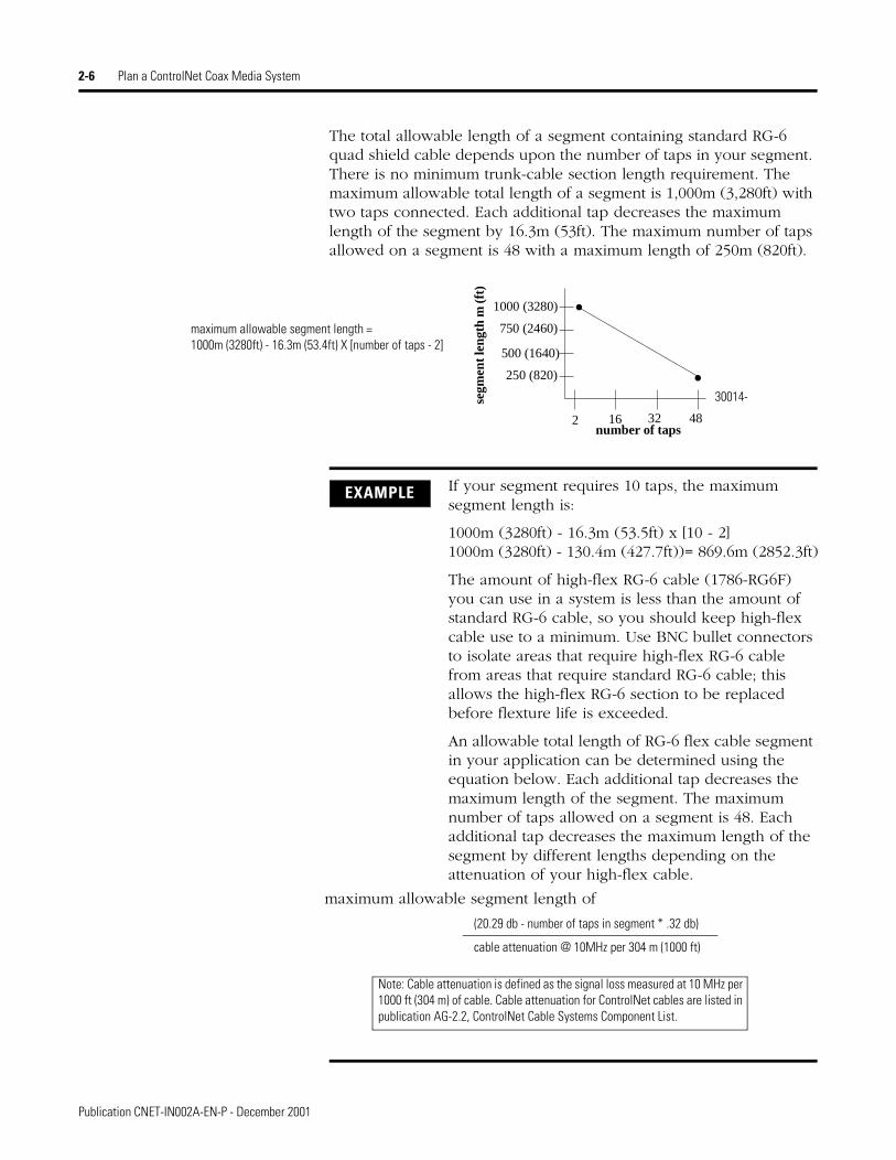
The total allowable length of a segment containing standard RG-6 quad shield cable depends upon the number of taps in your segment. There is no minimum trunk-cable section length requirement. The maximum allowable total length of a segment is 1,000m (3,280ft) with two taps connected. Each additional tap decreases the maximum length of the segment by 16.3m (53ft). The maximum number of taps allowed on a segment is 48 with a maximum length of 250m (820ft).
1000 (3280)
750 (2460)
500 (1640)
250 (820)
2 16 32 48
maximum allowable segment length =1000m (3280ft) - 16.3m (53.4ft) X [number of taps - 2]
number of taps
segm
ent l
engt
h m
(ft)
30014-
EXAMPLE If your segment requires 10 taps, the maximum segment length is:
1000m (3280ft) - 16.3m (53.5ft) x [10 - 2] 1000m (3280ft) - 130.4m (427.7ft))= 869.6m (2852.3ft)
The amount of high-flex RG-6 cable (1786-RG6F) you can use in a system is less than the amount of standard RG-6 cable, so you should keep high-flex cable use to a minimum. Use BNC bullet connectors to isolate areas that require high-flex RG-6 cable from areas that require standard RG-6 cable; this allows the high-flex RG-6 section to be replaced before flexture life is exceeded.
An allowable total length of RG-6 flex cable segment in your application can be determined using the equation below. Each additional tap decreases the maximum length of the segment. The maximum number of taps allowed on a segment is 48. Each additional tap decreases the maximum length of the segment by different lengths depending on the attenuation of your high-flex cable.
maximum allowable segment length of
(20.29 db - number of taps in segment * .32 db)
cable attenuation @ 10MHz per 304 m (1000 ft)
Note: Cable attenuation is defined as the signal loss measured at 10 MHz per 1000 ft (304 m) of cable. Cable attenuation for ControlNet cables are listed in publication AG-2.2, ControlNet Cable Systems Component List.
Publication CNET-IN002A-EN-P - December 2001

Plan a ControlNet Coax Media System 2-7
Determine How Many Terminators You Need
You must use 75Ω terminators (cat. no. 1786-XT) at the end of each segment for the ControlNet cable system to work.
After you have determined how many segments will be in your network, multiply this number by two to figure out how many terminators you will need for your network.
Determine if You Need Repeaters
You need to install repeaters if your system requires more than 48 taps per segment, or a longer trunk cable than the specifications allow.
The maximum number of addressable nodes per link (not counting repeaters) is 99. Since repeaters do not require an address, they do not count against the total of 99. If each segment is less than 250m, each segment could contain up to 47 nodes (48 connections are allowed on a 250m segment - 1 tap for the repeater).
EXAMPLE If your segment requires 3 taps using 1786-RG6F/B cable, the maximum segment length is:
([20.29 db - 3*.32 db] / 7.18 db] * 1000)(19.33 db / 7.18 db) * 1000 = 820 m (2692 ft)
The total trunk-cable length or number of taps can be increased by installing repeaters on the segment. This creates another segment.
1786-XT
1000 (3280)
750 (2460)
500 (1640)
250 (820)
2 16 32 48
s egm
ent l
e ngt
h m
(ft)
number of taps
Repeater required
Repeater not required
30016-m
Publication CNET-IN002A-EN-P - December 2001

2-8 Plan a ControlNet Coax Media System
Configure Your Link With Repeaters
When you configure your link using repeaters, you can install them in one of three ways:
A repeater can be connected to a segment at any tap location.
Install Repeaters in Series
When you install repeaters in series, use your ControlNet Network management Software (RSNetWorx) to verify that the system is an allowable configuration. The system size is based on the maximum number of repeaters (5) in a series and length of the media used between any two nodes.
Refer to the Installation Instructions that shipped with your repeater for an example series toplogy drawing.
ATTENTION
!Do not power both repeaters at the same time. Powering both repeaters at the same time disrupts communication on the network. Use the fault-relay contact of the primary repeater to control power to the backup repeater.
You can install repeaters in: See page:
series 2-8
parallel 2-9
a combination of series and parallel
2-9
ATTENTION
!The maximum system size is based on the distance between any two nodes. The total amount of cable used in the network is limited only by the distance between the farthest two nodes.
Publication CNET-IN002A-EN-P - December 2001

Plan a ControlNet Coax Media System 2-9
Install Repeaters in Parallel
When you install repeaters in parallel, you can install a maximum of 48 repeaters (the maximum number of taps per 250m segment) on any one segment.
If your link is configured using repeaters in parallel, you count one of the repeater taps for one segment and the other repeater tap for the parallel segment that the repeater is connecting to the backbone network.
Refer to the Installation Instructions that shipped with your repeater for an example parallel toplogy drawing.
Install Repeaters in a Combination of Series and Parallel
You can install repeaters in a combination of series and parallel connections to form a link. Follow the guidelines listed for each type.For mixed topologies (series and parallel), you can verify the maximum number of repeaters and media by using RSNetWorx.
Refer to the Installation Instructions that shipped with your repeater for an example combination series/parallel toplogy drawing.
TIP If your network is configured using repeaters in combination of series and parallel, you need to count the taps and repeaters in all segments.
Publication CNET-IN002A-EN-P - December 2001

2-10 Plan a ControlNet Coax Media System
Install Repeaters in a Ring
For a ring toplogy, you must use the ControlNet Long-distance Fiber Repeater (catalog number 1786-RPFRL) or Extra-long-distance Fiber Repeater (catalog number 1786-RPFRXL).
Refer to the Installation Instructions that shipped with your repeater for an example ring toplogy drawing.
Determine What Type of Connectors You Need
These connectors are available:
IMPORTANT You can order dust-tight (IP65) and corrosion-resistant (IP67) versions of these connectors. See the Allen-Bradley ControlNet Cable System Component List (publication AG-2.2) for a complete list of part numbers.
Use this connector: To:
cable connector attach trunk-cable sections to a tap’s BNC or TNC connector
bullet (jack-to-jack) reserve a space in the trunk cable for future installation of a tap or to splice a trunk cable
barrel (plug-to-plug) connect two adjacent taps without a trunk-cable section between them
isolated-bulkhead (jack-to-jack)
go through grounded panel walls while maintaining the shield isolation of the trunk-cable.
tap dummy load cap off installed taps that have yet to be connected to a node
right angle (jack-to-plug)
provide a 90° bend in your cable (prevents bending your cable excessively). See Chapter 3 for the bend radius specification.
Publication CNET-IN002A-EN-P - December 2001

Plan a ControlNet Coax Media System 2-11
Using Redundant Media (Optional)
You can run a second trunk cable between your ControlNet nodes for redundant media. With redundant media, nodes send signals on two separate segments. The receiving node compares the quality of the two signals and accepts the better signal to permit use of the best signal. This also provides a backup cable should one cable fail.
Trunk cables on a redundant cable link are defined by the segment number and the redundant trunk-cable letter.
Actual ControlNet products are labeled with these icons
(the shaded icon representing redundant media).
cable enters and exits from the side
barrel connector
In this example, ControlNet cable:• enters and exits the panel
enclosure from the side using isolated-bulkhead connectors
• contains two adjacent taps connected by a barrel connector
• reserves one future tap location with a bullet
20091-m
isolated-bulkhead connectorsbullet connector
panel wall
tapsright angle connectors
ATTENTION
!Do not let any metallic surfaces on the BNC connectors, plugs, or optional accessories touch grounded metallic surfaces. This contact could cause noise on the network.
IMPORTANT If you are installing a bullet connector for future tap installations, count the bullet as one of the tap allotments on your segment (and decrease the maximum allowable cable length by 16.3m [53.5ft]). This helps you avoid reconfiguring your network when you install the tap.
Publication CNET-IN002A-EN-P - December 2001

2-12 Plan a ControlNet Coax Media System
In this figure, the redundant cable trunk cable is trunk cable
B.
trunk cable A =
trunk cable B =
20134-m
node1 node1 node1
1 Node supporting redundant media
Publication CNET-IN002A-EN-P - December 2001
Plan a ControlNet Coax Media System 2-13
Observe these guidelines when planning a redundant media system.
• Route the two trunk cables (trunk cable A and trunk cable B) differently to reduce the chance of both cables being damaged at the same time.
• Each node on a redundant-cable link must support redundant Coax connections and be connected to both trunk cables at all times. Any nodes connected to only one side of a redundant-cable link will result in media errors on the unconnected trunk cable.
• Install the cable system so that the trunk cables at any physical device location can be easily identified and labeled with the appropriate icon or letter. Each redundant ControlNet device is labeled so you can connect it to the corresponding trunk cable.
• Both trunk cables (trunk cable A and trunk cable B) of a redundant-cable link must have identical configurations. Each segment must contain the same number of taps, nodes and repeaters. Connect nodes and repeaters in the same relative sequence on both trunk cables.
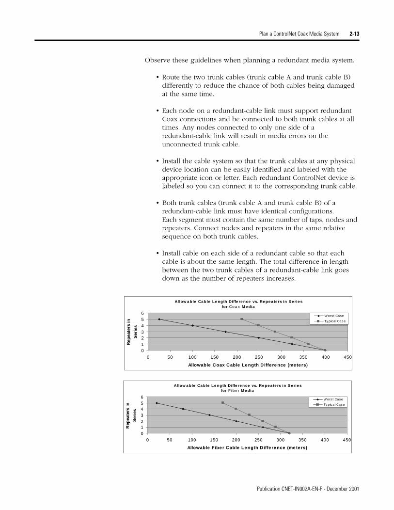
• Install cable on each side of a redundant cable so that each cable is about the same length. The total difference in length between the two trunk cables of a redundant-cable link goes down as the number of repeaters increases.
Allow a ble Ca ble Le ngth Diffe re nce vs. Re pe a te rs in S e rie sfor Coa x M e dia
0123456
0 50 100 150 200 250 300 350 400 450
Allowable Coax Cable Length Diffe re nce (meters)
Rep
eate
rs in
Ser
ies
Wors t Case
Typical Case
Allow a ble Ca ble Le ngth Diffe re nce vs. Re pe a te rs in S e rie sfor F ibe r M e dia
0123456
0 50 100 150 200 250 300 350 400 450
Allowable Fibe r Cable Le ngth D iffe re nce (me te rs)
Rep
eate
rs in
Ser
ies
Wors t Case
Ty pic al Cas e
Publication CNET-IN002A-EN-P - December 2001

2-14 Plan a ControlNet Coax Media System
• Avoid connecting a single node’s redundant trunk cable connections on different segments; this will cause erratic operation.
A node supporting redundant trunk-cable connections will function even if trunk cable A is connected to the B connector on the node and vice-versa. This makes cable fault indications (on the hardware or in software) difficult to interpret and makes locating a bad cable segment very difficult.
trunk cable A =
trunk cable B =
20135-m
node1 node1 node1
1 Node supporting redundant mediatrunk cable A =
node1
terminator
terminator
terminator
terminator
SEGMENT
SEGMENT
repeater
repeater
trunk cable B =
SEGMENT
SEGMENT
trunk cable A =
trunk cable B =
node1
node1 node1
1 Node supporting redundant media
trunk cable A =
trunk cable B =
terminator terminator
terminator
terminator
20136-m
repeater
repeater
Publication CNET-IN002A-EN-P - December 2001

Plan a ControlNet Coax Media System 2-15
Using IP67 Media Sealed media components are ControlNet taps and connectors suitable for use in harsh environments. The sealed tap contained in the ControlNet IP67 Tap and Connector Installation Kit (cat. no. 1786-TCT2BD1) protects the BNC connector, which is not water-tight.
The following figure shows a sample installation featuring IP67-rated sealed media components.
Application Considerations The following guidelines coincide with the guidelines for “the installation of electrical equipment to minimize electrical noise inputs to controllers from external sources” in IEEE standard 518-1982. When planning your cable system, take into account certain installation considerations, depending on your application.
IMPORTANT Refer to the ControlNet IP67 tap and Connector Kit Installation Instructions (supplied with the kit), publication 1786-IN017A-EN-P, for more information on IP67 installations.
31290-M
1786-BNC2TNC 1786-BNC2TNC
BNC to BNC drop cable
1786-TNCL10
1786-BNC/B
TNC to BNC drop cable
Wire Gland (not supplied by Rockwell Automation)
1786-TNCLP4
1786-TNCXTL4
TNC to TNC drop cable TNC to BNC
drop cable
1786-BNC/B
1786-TNCL10
1786-TNCL10
1786-TPIP67
1786-BNC2TNC
1786-TPS
1786-TNCL101786-BNC/B 1786-BNC/B 1786-TNCLP4
1786-RG-6 1786-RG-6
IP67-compliant device
Publication CNET-IN002A-EN-P - December 2001
2-16 Plan a ControlNet Coax Media System
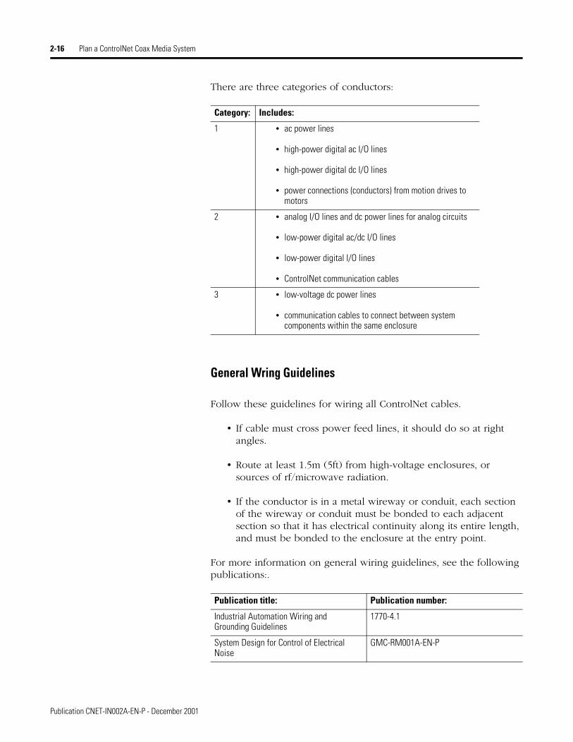
There are three categories of conductors:
General Wring Guidelines
Follow these guidelines for wiring all ControlNet cables.
• If cable must cross power feed lines, it should do so at right angles.
• Route at least 1.5m (5ft) from high-voltage enclosures, or sources of rf/microwave radiation.
• If the conductor is in a metal wireway or conduit, each section of the wireway or conduit must be bonded to each adjacent section so that it has electrical continuity along its entire length, and must be bonded to the enclosure at the entry point.
For more information on general wiring guidelines, see the following publications:.
Category: Includes:
1 • ac power lines
• high-power digital ac I/O lines
• high-power digital dc I/O lines
• power connections (conductors) from motion drives to motors
2 • analog I/O lines and dc power lines for analog circuits
• low-power digital ac/dc I/O lines
• low-power digital I/O lines
• ControlNet communication cables
3 • low-voltage dc power lines
• communication cables to connect between system components within the same enclosure
Publication title: Publication number:
Industrial Automation Wiring and Grounding Guidelines
1770-4.1
System Design for Control of Electrical Noise
GMC-RM001A-EN-P
Publication CNET-IN002A-EN-P - December 2001

Plan a ControlNet Coax Media System 2-17
Wiring External to Enclosures
Cables that run outside protective enclosures are relatively long. To minimize cross-talk from nearby cables, it is good practice to maintain maximum separation between the ControlNet cable and other potential noise conductors. You should route your cable following these guidelines:
Wiring Inside Enclosures
Cable sections that run inside protective equipment enclosures are relatively short. As with wiring external to enclosures, you should maintain maximum separation between your ControlNet cable and Category-1 conductors.
When you are running cable inside an enclosure, route conductors external to all raceways in the same enclosure, or in a raceway separate from Category-1 conductors.
Surge Suppression
Transient electromagnetic interference (EMI) can be generated whenever inductive loads such as relays, solenoids, motor starters,or motors are operated by “hard contacts” such as pushbutton or selector switches. These wiring guidelines assume you guard your system against the effects of transient EMI by using surge-suppressors to suppress transient EMI at its source.
Cable in a contiguousmetallic wireway or conduit?
Route your cable at least:
From noise sources of this strength:
Yes 0.08m (3”) Category-1 conductors of less than 20A
0.15m (6”) ac power lines of 20A or more, up to 100 KVA
0.3m (12”) ac power lines greater than 100 KVA
No 0.15m (6”) Category-1 conductors of less than 20A
0.3m (12”) ac power lines of 20A or more, up to 100 KVA
0.6m (24”) ac power lines greater than 100 KVA
Route your cable at least this distance:
From noise sources of this strength:
0.08m (3”) Category 1 conductors of less than 20A
0.15m (6”) ac power lines of 20A or more, up to 100 KVA
0.6m (24”) ac power lines greater than 100 KVA
Publication CNET-IN002A-EN-P - December 2001

2-18 Plan a ControlNet Coax Media System
Inductive loads switched by solid-state output devices alone do not require surge suppression. However, inductive loads of ac output modules that are in series or parallel with hard contacts require surge-suppression to protect the module output circuits as well as to suppress transient EMI.
Ferrite Beads
Ferrite beads can provide additional suppression of transient EMI. Fair-Rite Products Corporation manufactures a ferrite bead (part number 2643626502) which can be slipped over category-2 and category-3 (RG-6 type trunk cable) conductors. You can secure them with heat-shrink tubing or tie-wraps. A cable transient EMI induced onto the cable can be suppressed by a ferrite bead located near the end of the cable. The ferrite bead will suppress the EMI before it enters the equipment connected to the end of the cable.
Order Components Now that you are ready to order components, use these guidelines to help you select components.
Create a General Plan
The ControlNet cable system is isolated from earth and must be protected from inadvertent ground connections.
Plan Your Segments
• all connections to the trunk cable require a tap
• taps may be installed at any location on the trunk cable
• tap drop-cable length must not be changed
• maximum number of taps = 48, with 250m (820ft) of standard RG6 trunk cable
• maximum number of taps = 48, with 166.6m (546.75ft) of RG6F high- flex trunk cable
• maximum trunk-cable length of standard RG6 trunk cable = 1000m (3280 ft), with 2 taps
Publication CNET-IN002A-EN-P - December 2001

Plan a ControlNet Coax Media System 2-19
• maximum trunk-cable length of high-flex RG6F trunk cable = 666m (2187ft), with 2 taps
• 75Ω terminators are required on both ends
• one tap with an unconnected drop cable may be installed for maintenance purposes
• use BNC bullet connectors at future tap locations
• do not mix redundant and non-redundant nodes
• use dummy loads (1786-TCAP) for all other unconnected drop cables
• avoid high noise environments when routing cables
Link Planning
• maximum of 99 nodes (excluding repeaters)
• repeaters require a tap but are not counted as nodes — they are included in the number of devices allowed per segment (48)
• repeaters may be installed at any tap location along a segment
• there can only be one path between any two points on a link
• the configuration of both sides of a redundant segment must be the same
• The total difference in length between the two trunk cables of a redundant-cable link goes down as the number of repeaters increases. See the illustration on page 2-13.
Publication CNET-IN002A-EN-P - December 2001

2-20 Plan a ControlNet Coax Media System
Order Parts
What’s Next After you gather all of the parts for your ControlNet Coax media system, you are ready to install your network. Go to Chapter 3.
Item Cat. No. Guidelines Quantity needed1
Tapstraight T-tapstraight Y-tapright angle T-tapright angle Y-tap
see the ControlNet Cable System Component List (publication AG-2.2)
You need a tap for each connection to the trunk cable (nodes and repeaters).Each tap kit contains: two BNC connector kits, 1 dust cap, 1 universal mounting bracket, ControlNet cable labels and 2 screws
number of repeaters x 2+ number of nodes
repeater8 Use a repeater to:increase the number of nodes attachedextend the allowable cable length
Follow guidelines on page 7.
terminators You need a terminator for each end of each segment.
number of segments x 2
network access cable Use this cable to temporarily connect programming devices (through NAPs)to ControlNet nodes.
number of programming devices
cable connector Two cable connectors are shipped with each tap — you need to order additional cable connectors for each bullet and isolated-bulkhead connector you will be using.2
number of bullet connectors x 2+number of isolated-bulkhead connectors x 2+any spares
optional bullet cablebarrel connectors
isolated-bulkhead
Use these as specified on page 10. depends on your network requirements
right angleextendertrunk cable Use the ControlNet Cable System
Component List (publication AG-2.2)to order your required length of cable.
See page 5 to select your cable type.Follow guidelines on page 5 to determine cable length.
tap dummy load 1786-TCAP(quantity of 5)
Use the dummy load to plug into drop cables that are not attached to a node
one for every drop cable that is not attached to a node
Coax tool kit 1786-CTK Use the tool kit to create your create your trunk cable to your specifications
one
1 You will need to double your quantities when ordering components for a redundant cable system.2 The connector kit may be shipped with two ferrules. The smaller diameter ferrule should not be used with ControlNet applications.
Publication CNET-IN002A-EN-P - December 2001

Chapter 3
Install a ControlNet Coax Media System
What’s in This Chapter Follow the instructions in this chapter to install your ControlNet Coax Media system.
For information about this topic: See page:
Install the Trunk Cable 3-2
Mount the Taps 3-2
Install a Repeater Adapter 3-5
Install Cable Connectors 3-6
Collect Your Tools 3-6
Calibrate the Cutting Blades 3-7
Strip the Cable 3-19
Attach the Connectors to the Cable 3-14
Test for Electrical Shorts and Continuity 3-18
Connect Cable Sections 3-19
Terminate Segments 3-20
Connect Devices 3-21
IMPORTANT Read Chapter 2, Plan a ControlNet Coax Media System, before you install your network.
IMPORTANT To ensure the integrity of your ControlNet connection, use only Rockwell Automation cables and connectors, as well as the ControlNet Coax Toolkit, catalog number 1786-CTK.
1 Publication CNET-IN002A-EN-P - December 2001

3-2 Install a ControlNet Coax Media System
Install the Trunk Cable Install your trunk cable, observing your cable supplier’s installation instructions and these guidelines.
Wire the External to Enclosures
When you pull the RG-6 type Coax cable through multiple conduit bends, follow these specifications.
Wire Inside Enclosures
When you do not pull the RG-6 type Coax cable through conduit, follow these specifications.
Mount the Taps To mount the taps you:
• select where you want to mount the taps based on the topology design that you planned in Chapter 2 of this manual.
• mount the taps
Select Where To Mount The Taps
• There is no spacing requirement between taps; you can install two adjacent taps if necessary by using a barrel connector (1786-BNCP).
• Be certain that the location where you are going to mount a tap is convenient for your cable route.
For this Coax cable:
The pull strength should not exceed:
The bend radius should not exceed:
PVC 42.75kg (95lbs) 76.2mm (3.0”)
FEP 61.65kg (137lbs) 69.9mm (2.75”)
For this Coax cable: The bend radius should not exceed:
PVC 38.1mm (1.5”)
FEP 35.6mm (1.4”)
Tap drop-cable 25.4mm (1.0”)
Publication CNET-IN002A-EN-P - December 2001

Install a ControlNet Coax Media System 3-3
• Be certain that the location where you are going to mount does not cause any cable bend radii to exceed the limits listed on page 3-2.
• Do not mount the tap in a position that routes the drop cable over any ac power terminals on nearby modules.
Mount the Taps
You can mount your ControlNet taps (Y-tap and T-tap):
• to a universal mounting bracket, and then mount the tap and bracket as an assembly
• through the body holes in the tap using:
– screws and flat washers
– a tie wrap
Mount a Tap With a Universal Mounting Bracket
1. Align the universal mounting bracket with the mounting holes on the tap.
ATTENTION
!Do not allow any metal portions of the tap, such as the universal mounting bracket screws or connectors, to contact any conductive material.This contact could cause noise on the network.
TIP See Appendix A for universal mounting bracket and tap mounting dimensions.
Publication CNET-IN002A-EN-P - December 2001

3-4 Install a ControlNet Coax Media System
2. Using the screws provided with the tap, attach the tap to the universal mounting bracket.
3. Mount the tap and bracket assembly to:
universal mounting bracket (provided with tap)
universal mounting bracket
Use only the screws that are packaged with the tap. They are the proper length and head style.
20084-m
Y-Tap
T-Tap
dust cap
dust cap
Mount the universal mounting bracket on specified Allen-Bradley mounting rails or DIN rails #3 style symmetrical (35mm X 7.5mm)
Use four screws to attach the universal mounting bracket to another mounting surface.
a DIN mounting rail or another mounting surface
Type of rail Cat. No. Type of Rail Cat. No.A-B rail 1492-N1 DIN rail #3 199-DR1
1492-N22 1492-DR51492-N44 1492-DR6
1492-DR7
20081-m 20082-m
DIN railsuitable fixture
universal mounting bracket
universal mounting bracket
Publication CNET-IN002A-EN-P - December 2001

Install a ControlNet Coax Media System 3-5
Mount a Tap Through the Body Holes
Mount the tap to a suitable fixture using:
Install a Repeater Adapter Refer to the ControlNet Modular Repeater Adapter Installation Instructions, publication 1786-IN013A-EN-P, for instructions on installing the repeater adapter.
You can use a variety of screw types.
20083-m
body holes
body holes
tie wrap
screws and flat washers
ATTENTION
!Do not over-tighten the screws. Over tightening the screws can damage the tap. The applied torque should be 0.2-0.4 Nm (1-2 ft-lbs).
IMPORTANT The suitable fixture can be conductive and/or grounded because of the electrical isolation provided by these body holes.
Publication CNET-IN002A-EN-P - December 2001

3-6 Install a ControlNet Coax Media System
Install Cable Connectors After you have mounted the taps, you need to attach cable connectors to the ends of your trunk-cable sections.
Collect Your Tools To install the cable connectors, we recommend that you use the tools in the ControlNet Coax Toolkit, catalog number 1786-CTK.
To: See page:
collect your tools 3-6
calibrate the cutting blades 3-7
strip the cable 3-9
attach the cable connectors 3-14
test for electrical shorts and continuity 3-18
wire cutters
crimp tool
knife
calibration/flare tool
memory blade holder memory blade cartridges
terminators and extraconnectors
cable strip tool with
one for PVC and one for FEP two blade cassettes
contains two sets of memory blades41902
ControlNet Network Component List, publication AG-2.2
ControlNet Network Coax MediaPlanning and Installation Manual,publication CNET-IN002-EN-P.
Publication CNET-IN002A-EN-P - December 2001

Install a ControlNet Coax Media System 3-7
Locally Available Tools
You will also need these local-purchase tools (not supplied in the kit):
• 3/32” Allen wrench
• heat gun (if you are installing IP65 or IP67 corrosion-resistant connectors)
Calibrate the Cutting Blades
Use the following procedure to calibrate your cable strip tool to cut FEP or PVC cable.
1. Turn the three screws outward to back the blades out. This prevents the calibration tool from bottoming out.
2. Place the calibration tool into the cable strip tool with the narrow end installed and facing forward for FEP cable (use the wider end for PVC).
3. Tighten the chamber gauge ring so that the calibration tool is locked in place. Close all the way to the chamber gauge stop.
ATTENTION
!Be certain to perform the calibration procedure the first time you use the tool and every time you change the blade for both memory cartridges. Due to slight differences between Coax cables, calibration should be performed when changing:
• part numbers
• from one cable manufacturer to another
2088-m
adjusting screws To: Turn the screw:
increase the cut depth clockwise
decrease the cut depth counterclockwise
41892FEP
PVCcalibration tool
IMPORTANT When aligned properly, the grooves of the calibration tool should align with the blades.
Publication CNET-IN002A-EN-P - December 2001

3-8 Install a ControlNet Coax Media System
4. Adjust the screws of the memory clip so that the blades just touch the calibration tool.
5. Retract the handle of the cable strip tool.
6. Remove the calibration tool from the cable strip tool.
When you are finished, the blade should make a cut of the following dimensions in your cable.
ATTENTION
!Do not over-tighten the screws of the cable strip tool. The blades should not bend, shift, or penetrate the calibration tool.
First Cut: all four shield layers-braid/tape/braid/tape
Second Cut: white insulation or 1st tape
Third Cut: center conductor
The first cut should cut the outer sheath without cutting the outer wire braid. If the braid is frayed, scored, or cut by the blade, adjust the blade outward slightly to eliminate the fraying.
The second cut should cut the sheath, three outer shields, and possibly the inner tape shield. The insulation can be scored slightly, but should not have a deep cut.
The third cut should cut all layers of the cable down to the center conductor. This cut should not score the center conductor. If the blade leaves a mark on the conductor, adjust the blade slightly so to eliminate marking the conductor.
8.3 mm 3.7 4.0
30030-m
PVC CL2
IMPORTANT The first and second cut adjustments need to be precise. Adjustments as small as 1/12 to 1/8 of a turn can make the difference between a perfect and an imperfect cut.
Publication CNET-IN002A-EN-P - December 2001
Install a ControlNet Coax Media System 3-9
Strip the Cable
When cutting cable sections, make them long enough to route from one tap to the next with sufficient length so that the bend radius is not less than:
• 76.2mm (3”) for wiring external to enclosures
• 38.1mm (1.5”) for wiring inside enclosures
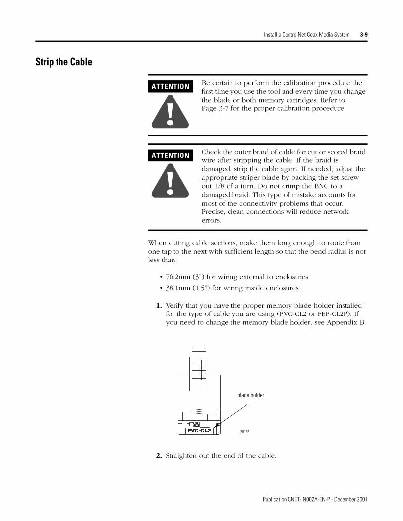
1. Verify that you have the proper memory blade holder installed for the type of cable you are using (PVC-CL2 or FEP-CL2P). If you need to change the memory blade holder, see Appendix B.
2. Straighten out the end of the cable.
ATTENTION
!Be certain to perform the calibration procedure the first time you use the tool and every time you change the blade or both memory cartridges. Refer to Page 3-7 for the proper calibration procedure.
ATTENTION
!Check the outer braid of cable for cut or scored braid wire after stripping the cable. If the braid is damaged, strip the cable again. If needed, adjust the appropriate striper blade by backing the set screw out 1/8 of a turn. Do not crimp the BNC to a damaged braid. This type of mistake accounts for most of the connectivity problems that occur. Precise, clean connections will reduce network errors.
blade holder
20165
Publication CNET-IN002A-EN-P - December 2001

3-10 Install a ControlNet Coax Media System
3. Insert the cable into the cable strip tool’s cutting chamber so that approximately 25.4mm (1”) of extra cable extends beyond the edge of the tool.
4. Lock the cable into place by moving the chamber-gauge ring forward until it meets the cable with slight resistance.
25.4 mm (1") extra cable
20073cable
This gauge moves two rollers toward the cable and regulates the depth of the cut.The gauge will "click" as it moves from one gauge to the next.
20073
Publication CNET-IN002A-EN-P - December 2001

Install a ControlNet Coax Media System 3-11
5. Holding the cable in one hand, place the index finger of your other hand inside the chamber-gauge ring and turn the strip tool 360° around the cable. Turn four or five full rotations until the strip tool glides easily around the cable.
6. After you have moved the chamber gauge ring to the last position and turned the strip tool the final time:
a. Move the chamber gauge ring backward to release the strip tool and remove it from the cable.
b. If you are using Allen-Bradley IP65 and IP67 corrosion-resistant connectors, slide the heat shrink tubing over the cable.
c. Slip the crimp ferrule onto the cable. Push it back to the sheath area of the cable to keep it out of the way for the moment.
d. Strip away the appropriate portion of the cable without using the strip tool.
IMPORTANT On your last repetition of steps 4 and 5, apply sufficient pressure on the chamber gauge ring to make sure the ring has reached the last stage. The chamber gauge should read ‘stop’ for the last repetition.
Repeat steps 4 and 5, moving the chamber gauge ring forward one notch for each time you repeat the steps, until you reach the last notch.Each time you move the chamber gauge ring forward a notch, the strip tool makes a deeper cut into the cable.
20074
crimp ferrule
cable41887a
Publication CNET-IN002A-EN-P - December 2001
3-12 Install a ControlNet Coax Media System
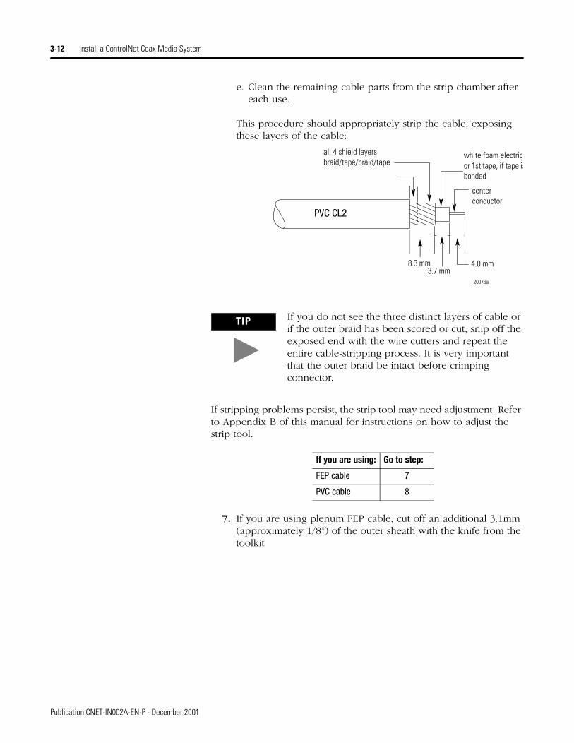
e. Clean the remaining cable parts from the strip chamber after each use.
This procedure should appropriately strip the cable, exposing these layers of the cable:
If stripping problems persist, the strip tool may need adjustment. Refer to Appendix B of this manual for instructions on how to adjust the strip tool.
7. If you are using plenum FEP cable, cut off an additional 3.1mm (approximately 1/8”) of the outer sheath with the knife from the toolkit
TIP If you do not see the three distinct layers of cable or if the outer braid has been scored or cut, snip off the exposed end with the wire cutters and repeat the entire cable-stripping process. It is very important that the outer braid be intact before crimping connector.
If you are using: Go to step:
FEP cable 7
PVC cable 8
all 4 shield layersbraid/tape/braid/tape
white foam electric or 1st tape, if tape isbonded
center conductor
8.3 mm3.7 mm
4.0 mm
20076a
PVC CL2
Publication CNET-IN002A-EN-P - December 2001

Install a ControlNet Coax Media System 3-13
.
8. Be certain that the center conductor is 4.0 mm. Use the imprint guide on the back of the ControlNet tap or the calibration tool to verify this.
all four shield layersbraid/tape/braid/tape
white insulation or 1st tape
center conductor
sheath
11.44 mm3.7 mm
4.0 mm
20076a
FEP CL2P
PVC/CL2 FEP/CL2P
center conductor PVC cable only
T-tap
PVC Cable
4.0 mm
3.7 mm 8.3 mm
Use this end of the calibration tool to verify proper measurements for FEP cable.
The center conductor should be 4.0 mm exactly. If the center conductor is too long, cut off the excess with the wire cutter from the cable kit. If it is too short, repeat the entire cable stripping process.
PVC/CL2 FEP/CL2P
calibration/flare tool
41952
ATTENTION
!Check for any braid stranding that may not have been cut to the proper length. If one strand comes in contact with the center conductor, it could short out the cable. If you find any such strands, cut them to the correct length.
Publication CNET-IN002A-EN-P - December 2001

3-14 Install a ControlNet Coax Media System
Attach the Connectors to the Cable
This section tells you how to install standard or corrosion-resistant connectors.
1. Push the flare tool onto the cable and with a slight twisting motion (with sufficient inward pressure) to expand the braid.
2. .Place the center pin over the center conductor.
ATTENTION
!Check the outer braid of cable for cut or scored braid wire after you strip the cable. If the braid is damaged, cut off the end and strip the cable again. You may need to adjust the appropriate striper blade by backing the set screw out 1/8 of a turn. Do not crimp the BNC to a damaged braid. This type of mistake accounts for most of the connectivity problems that can occur. Precise, clean connections will reduce network errors.
IMPORTANT Be certain that the center pin slips onto the center conductor completely. The back shoulder of the center pin should be up against the white insulation. If it is not, recheck the length of the center conductor.
41888
center conductor
center pin
41889
Sometimes strands of insulation remain on the center conductor. Be sure that the center conductor is clean before installing the center pin.
Publication CNET-IN002A-EN-P - December 2001

Install a ControlNet Coax Media System 3-15
3. With the center pin in place, use the crimp tool to crimp the pin into place.
4. Slide the ControlNet connector onto the cable.
41890
Push the flare/calibration tool gently and rotate slightly onto the connector while applying pressure. This will work the base of the connector underneath the wire braid slowly.
41903
The smaller hexagonal crimping notch is for crimping the center pin onto the center connector.
Check for braid strands that could cause a short to center conductor.
41896
braid and tape shields
connector base
Publication CNET-IN002A-EN-P - December 2001

3-16 Install a ControlNet Coax Media System
5. Slide the crimp ferrule over the three outer shields and connector base until it meets the shoulder on the connector.
6. Using the crimp tool, crimp the ferrule. Position the crimp tool on the ferrule as close as possible to the connector base and ferrule meeting line. Press the tool tightly around the ferrule until the crimp tool allows release.
20077e
crimp ferrule
The larger hexagonal crimping notch is for crimping the ferrule which holds the connector to the cable.
Publication CNET-IN002A-EN-P - December 2001

Install a ControlNet Coax Media System 3-17
7. If your installation requires IP67-rated connectors:
a. If your installation requires IP67-rated connectors, slide the heat-shrink tubing onto the cable.
b. Place the crimp ring on to the cable.
c. Strip the cable using the 1786-CTK stripper tool.
d. Remove an extra 1/8 inch of the jacket from the cable. Be careful not to cut the braid.
e. Trim the center conductor to the required length as directed on the connector bag..
8. Follow these guidelines when heating the tubing:
a. Place the tubing against the shoulder of the TNC connector.
b. Allow the heat gun to come to a temperature of between 110 and 160 degrees Celsius.
c. Hold the cable assembly approximately 2 inches away from the heat exhaust area of the heat gun while shrinking the tubing.
d. Continuously rotate the cable assembly around the heat exhaust area of the heat gun. The entire process should take about 4 minutes.
TIP Many network problems are due to improperly installed connectors. You should have tight-fitting connectors on the ends of all your cables. Pull the connector to verify that it is attached. If it is loose or comes off, snip off the connector and install a new one. The connector should withstand a minimum 60lbs pull force if properly installed.
IMPORTANT Use only the ACUM heat-shrink tubing provided in the IP67 Tap and Cable Kit. Do not substitute other types of heat-shrink tubing. Substitutions may cause a loss of the IP67 rating.
ATTENTION
!Be careful when using heat guns. High temperatures can lead to burns, risk of fire, or other property damage.
Publication CNET-IN002A-EN-P - December 2001

3-18 Install a ControlNet Coax Media System
e. Inspect the heat-shrink tubing to ensure that there are no voids where the glue has incompletely melted. Voids could cause a loss of the IP67 rating.
Test for Electrical Shorts and Continuity
1. Using the NetLinx Media Checker (catalog number 1788-MCHKR) is the preferred method for continuity testing. Attach the connector end of the cable to the port on top of the Media Checker.
2. As a secondary method, you can also use an ohmmeter or continuity tester to test for a short between the connector body and pin.
3. Use shorting clips to connect a temporary short between the pin and connector body at one end of the cable.
31297-M
Place the tubing against the shoulder of the TNC connector
Ensure that there are no voids where glue has incompletely melted
31195-M
LENGTHWIRE MAPTEST
SETUP ENTER
OFF
MediaChecker
1788-MCHKR
Attach the connector end of the cable to the port on top of the NetLinx Media Checker
20166
connector body
pin
Publication CNET-IN002A-EN-P - December 2001
Install a ControlNet Coax Media System 3-19
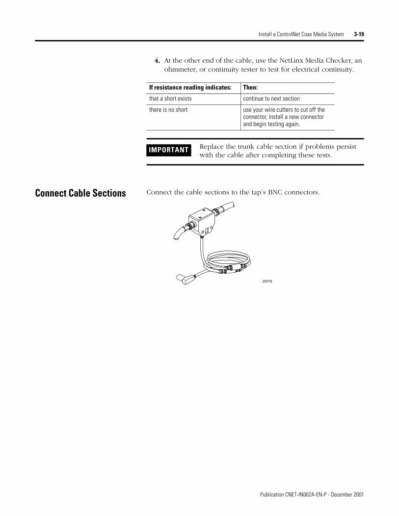
4. At the other end of the cable, use the NetLinx Media Checker, an ohmmeter, or continuity tester to test for electrical continuity.
Connect Cable Sections Connect the cable sections to the tap’s BNC connectors.
If resistance reading indicates: Then:
that a short exists continue to next section
there is no short use your wire cutters to cut off the connector, install a new connector and begin testing again.
IMPORTANT Replace the trunk cable section if problems persist with the cable after completing these tests.
20078
Publication CNET-IN002A-EN-P - December 2001

3-20 Install a ControlNet Coax Media System
Terminate Segments The taps on the ends of the segment have only one cable connector attached to them. This leaves an open, or unterminated, end on the segment. Signals transmitted along the cable will reflect off these unterminated ends and interfere with transmission.
To eliminate signal reflections from the ends of the segment, you must attach a 75Ω terminator to the first and last taps on the segment. The terms “first” and “last” refer to the physical location of the node along the trunk cable.
5. Connect one end of the trunk-cable section to one of the tap’s BNC connectors.
6. Install a 75Ω terminator onto the tap’s other BNC connector.
20078
Repeat steps 1 and 2 at the other end of the segment
20079
1786-XT
Publication CNET-IN002A-EN-P - December 2001
Install a ControlNet Coax Media System 3-21
Connect Devices After terminating your segments, you connect your devices.
1. Remove and save the tap’s dust cap (located on the straight orright-angle connector).
2. Connect the tap’s straight or right-angle connector to your device.
Connect Programming Terminals Through the NAP
Use the ControlNet™ network access cable (1786-CP) to connect a programming terminal to any intelligent device (i.e. workstation,
PLC® processor, or adapter) on a ControlNet link through the network access port (NAP).
1. Connect one end of the 1786-CP cable to the NAP on the front of the ControlNet node.
To connect a See
programming terminal through the NAP page 3-21
repeater page 3-22
ControlNet processor, adapter or programming terminal via a communication interface
procedure below
If your node supports: Connect the tap’s straight or right-angle connector:
non-redundant media to the channel A connector on the device (channel B is not used)1
redundant media • from trunk cable A to channel A on the your device
• from trunk cable B to channel B on the your device
1 While both channels are active, Allen-Bradley recommends using channel A for non-redundant media.
Publication CNET-IN002A-EN-P - December 2001

3-22 Install a ControlNet Coax Media System
2. Connect the other end of the 1786-CP cable to the NAP on the ControlNet communication interface installed in (or connected to) your programming terminal.
Connect the Repeater to a ControlNet Link
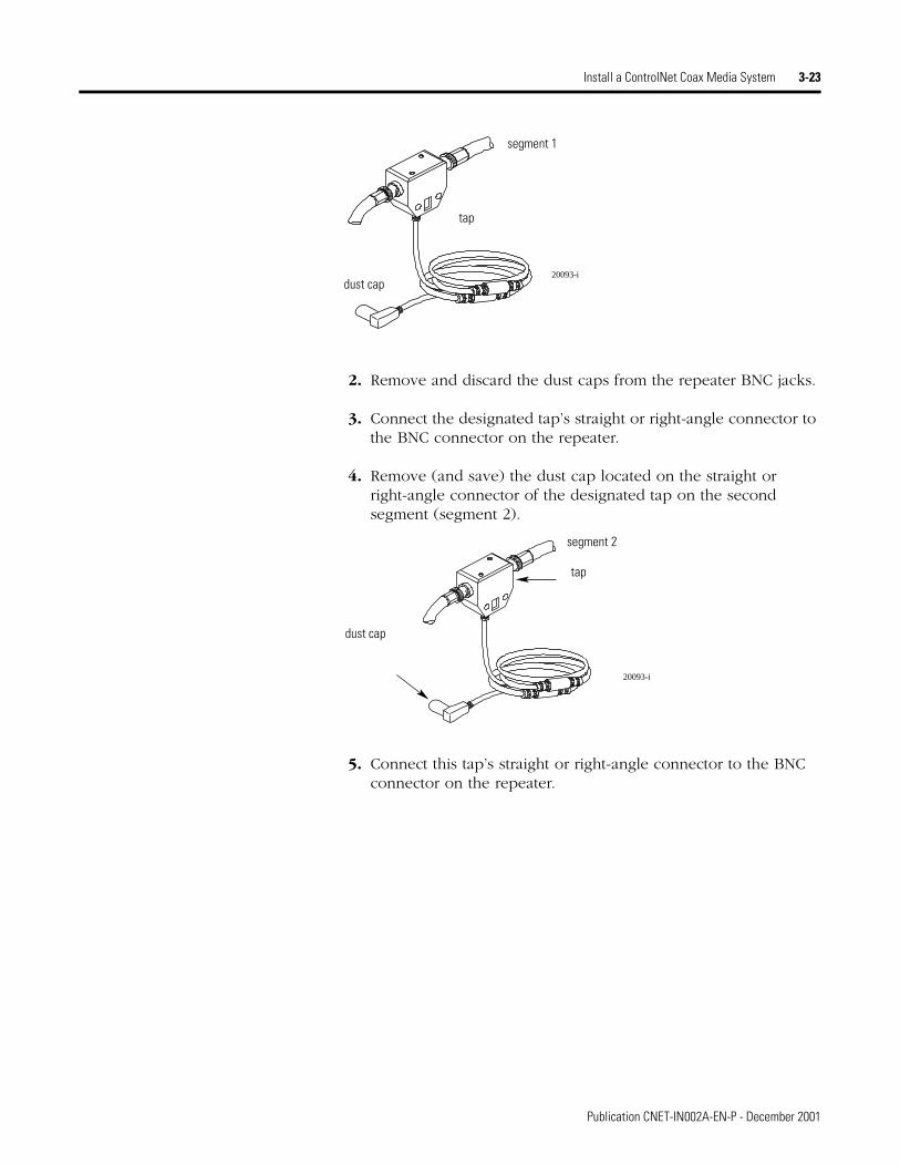
1. Remove (and save) the dust cap located on the straight or right-angle connector of the designated tap on the first segment (segment 1).
ATTENTION
!Do not use the 1786-CP cable as shown below. These connections could result in network failures.
ATTENTION
!Do not allow any metal portions of the tap to contact any conductive material. This contact can cause noise on the network.
If you disconnect the tap from the repeater, place the dust cap back on the straight or right-angle connector to prevent the connector from accidentally contacting a metallic grounded surface.
Do not use the 1786-CP cable to connect your programming device to ControlNet two ways simultaneously
Do not use the 1786-CP cable to connect a scanner or adapter module to a PLC processor
Do not use the 1786-CP cable to connect two separate ControlNet segments
1786-CP
1786-CP
1786-CP
1786-CP
20140
Publication CNET-IN002A-EN-P - December 2001
Install a ControlNet Coax Media System 3-23
2. Remove and discard the dust caps from the repeater BNC jacks.
3. Connect the designated tap’s straight or right-angle connector to the BNC connector on the repeater.
4. Remove (and save) the dust cap located on the straight or right-angle connector of the designated tap on the second segment (segment 2).
5. Connect this tap’s straight or right-angle connector to the BNC connector on the repeater.
20093-i
segment 1
tap
dust cap
20093-i
tap
dust cap
segment 2
Publication CNET-IN002A-EN-P - December 2001

3-24 Install a ControlNet Coax Media System
Notes:
Publication CNET-IN002A-EN-P - December 2001
Appendix A
Mounting Dimensions
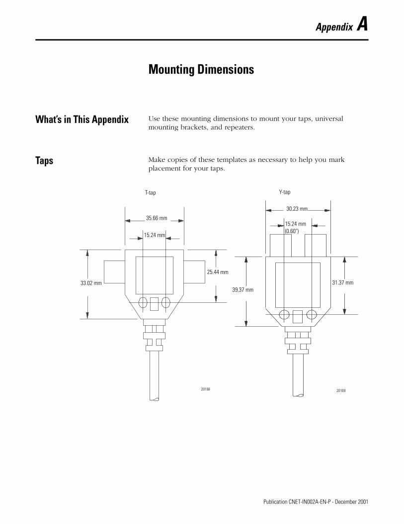
What’s in This Appendix Use these mounting dimensions to mount your taps, universal mounting brackets, and repeaters.
Taps Make copies of these templates as necessary to help you mark placement for your taps.
T-tap Y-tap
35.66 mm
15.24 mm
33.02 mm
25.44 mm
39.37 mm 31.37 mm
30.23 mm
15.24 mm (0.60")
20168 20169
1 Publication CNET-IN002A-EN-P - December 2001

A-2 Mounting Dimensions
Universal Mounting Bracket
58.42 mm (2.30")49.53 mm (1.95")
15.47 mm (0.609")
9.53 mm 30.94 mm (1.128")
19.05 mm (0.75")
20170-m
Publication CNET-IN002A-EN-P - December 2001

Appendix B
Maintain the Cable Strip Tool
What’s in This Appendix Follow the instructions in this appendix to perform the following tasks on the cable strip tool, supplied with the ControlNet Coax Toolkit (1786-CTK):
Reverse/Replace the Cutting Blades
To reverse or change the cutting blades:
1. Use a screwdriver to lift the memory blade holder and swing it back.
For information about this topic: See page:
Reverse/Replace the Cutting Blades B-1
Change the Memory Blade Holder B-3
20182-m
1 Publication CNET-IN002A-EN-P - December 2001

B-2 Maintain the Cable Strip Tool
2. Slide the memory blade cartridge out of the strip tool.
3. Flip the memory blade cartridge and slide it back into the strip tool.
Go to step 5.
20183-m
If you are: Go to:reversing the memory blade cartridge to use the second set of blades
the next step
replacing the memory blade cartridge step 4
30031-m
Publication CNET-IN002A-EN-P - December 2001

Maintain the Cable Strip Tool B-3
4. Align the memory blade cartridge (the side with the raised notches) to the raised area on the inside of the strip tool and slide the new memory blade cartridge in — the blades should be on top as you slide the cartridge in.
5. Swing the memory blade holder closed.
Change the Memory Blade Holder
You received two memory blade holders with your cable strip tool; one is for PVC-CL2 cable, and the other is for plenum FEP-CL2P cable. You need to install the appropriate memory blade holder for the type of cable you are stripping (PVC or FEP).
1. Lift the latches on the memory blade holder and swing it back.
raised area
raised notch
30031a-m
20069-m
20182-m
Publication CNET-IN002A-EN-P - December 2001

B-4 Maintain the Cable Strip Tool
2. Snap the memory blade holder off the rod andremove it from the strip tool.
3. Position the appropriate memory blade holder on the rod and snap the holder into place.
4. Swing the memory blade holder closed.
20070-m
20069-m
Publication CNET-IN002A-EN-P - December 2001
Index
Aabbreviations and symbols 1application considerations 2-15
Bbarrel connector 2-10, 2-20BNC cable connectors 1-4, 2-10
installing 3-6bridge 1-1bullet connector 2-2, 2-10, 2-20
Ccable connectors 1-4, 2-10
barrel 2-10, 2-20bullet 2-10, 2-20extender 2-20installing 3-6isolated bulkhead 2-10, 2-20right angle 2-10, 2-20
catalog numbers1770-KFC 2-31784-KTC 2-31784-KTCX 2-31786-BNCP 3-21786-CP 2-3, 3-211786-CTK 3-6, 3-71786CTK B-11786-XT 1-4, 2-7, 3-20
categories of conductors 2-16coax cable 2-4continuity tester 3-18ControlNet cable system
application considerations 2-15cable connector
bullet 2-2cable connectors 1-4, 2-10, 2-20
optional 1-4Coax Toolkit 3-6component definitions 1-1connecting cable sections 3-19connecting devices 3-21connecting programming terminals through NAP 3-21determine
cable needed 2-4number of repeaters 2-7number of taps 2-1number of terminators needed 2-7
trunk cable section lengths 2-5type of cable connectors needed 2-10
ferrite beads 2-18installing
cable connectors 3-6trunk cable 3-2
link 1-1, 1-6, 2-18repeater configurations 2-8
mounting taps 3-2network 1-1network access cable 2-3, 2-20node 1-2, 1-3ordering components 2-18planning guidelines 2-18redundant media 2-11, 2-13related publications 1repeater 1-2, 1-5, 2-7, 2-20
connecting to a link 3-22segment 1-2, 1-5, 2-18stripping trunk cable 3-9surge suppression 2-17tap 1-2, 2-1, 2-20
mounting dimensions A-1terminating segments 3-20terminator 2-20terminators 1-2, 1-4, 2-7testing for electrical continuity 3-18trunk cable 1-2, 1-4, 2-20
testing 3-18wiring 2-16wiring external to enclosures 2-17wiring inside enclosures 2-17
trunk cable section 1-2, 1-4, 2-5universal mounting bracket
mounting dimensions A-2wiring guidelines 2-16
ControlNet Coax Toolkitcrimp tool 3-15knife 3-12strip gauge 3-13strip tool 3-10
adjusting the cutting blades B-1changing the memory blade holder B-3
crimp tool 3-15
Eextender cable connector 2-20
Publication CNET-IN002A-EN-P - December 2001

2 Index
FFEP cable 1, 2-5, 3-2, 3-9, 3-12, B-3ferrite beads 2-18
GGMC-RM001A-EN-P 2-16
Iinstalling cable connectors
stripping the cable 3-12stripping trunk cable 3-9
isolated bulkhead connector 2-10, 2-20
Llink 1-6
definition 1-1planning 2-18
Mmedia
redundant 2-11guidelines 2-13
memory blade holder 3-9mounting dimensions
tap A-1universal mounting bracket A-2
NNAP 2-3, 2-20, 3-21NetLinx Media Checker 3-18network access cable 2-3node 1-2, 1-3
Oohmmeter 3-18ordering components 2-18
Pprogramming terminals
connecting through NAP 3-21ways to connect to a ControlNet link 2-3
publications 11770-4.1 1, 2-16AG-2.2 1, 2-5, 2-10, 2-20
PVC cable 1, 2-5, 3-2, 3-9, 3-12, B-3
Rredundant media 2-11
guidelines 2-13repeater 1-2, 1-5, 2-7
connecting to a ControlNet link 3-22European Union directive compliance 3-6installed in parallel 2-9installed in series 2-8installed in series and parallel 2-9
repeater configurationsinstalled in parallel 2-9installed in series 2-8installed in series and parallel 2-9
RG-6 cable 2-4, 3-2right angle connector 2-20right-angle connector 2-10Rockwell Automation support 2
local product support 2questions or comments about manual 3technical product support 3
Ssegment 1-2, 1-5
planning 2-18terminating 3-20
strip tooladjusting the cutting blades 3-7changing the memory blade holder B-3reversing/replacing cutting blades B-1
support 2local product support 2questions or comments about manual 3technical product assistance 2
surge suppression 2-17
Ttap 1-2, 1-3, 2-20
determine number needed 2-1mounting 3-2
to a universal mounting bracket 3-3using the body holes 3-5
mounting dimensions A-1selecting where to mount 3-2
techniques used in the manual 2terminators 1-2, 1-4, 2-7testing for electrical shorts and continuity 3-18trunk cable 1-2, 1-4
bend radius 3-2
Publication CNET-IN002A-EN-P - December 2001

Index 3
installing 3-2pull strength 3-2stripping 3-9terminating 3-20testing for shorts and continuity 3-18wiring external to enclosures 2-17, 3-2wiring inside enclosures 2-17, 3-2
trunk cable section 1-2, 1-4, 2-5, 3-19
Uuniversal mounting bracket
mounting dimensions A-2
WWeb addresses 3wiring
external to enclosures 2-17, 3-2inside enclosures 2-17, 3-2
wiring guidelines 2-16
Publication CNET-IN002A-EN-P - December 2001

4 Index
Publication CNET-IN002A-EN-P - December 2001

How Are We Doing?Your comments on our technical publications will help us serve you better in the future.Thank you for taking the time to provide us feedback.
You can complete this form and mail it back to us, visit us online at www.ab.com/manuals, or
email us at [email protected]Please complete the sections below. Where applicable, rank the feature (1=needs improvement, 2=satisfactory, and 3=outstanding).
Pub. Title/Type ControlNet Coax Media Planning and Installation Guide
Cat. No. 1786-series Pub. No. CNET-IN002A-EN-P Pub. Date October 2001 Part No. 955135-80
Overall Usefulness 1 2 3 How can we make this publication more useful for you?
Completeness(all necessary information
is provided)
1 2 3 Can we add more information to help you?
procedure/step illustration feature
example guideline other
explanation definition
Technical Accuracy(all provided information
is correct)
1 2 3 Can we be more accurate?
text illustration
Clarity(all provided information is
easy to understand)
1 2 3 How can we make things clearer?
Other Comments You can add additional comments on the back of this form.
Your Name Location/Phone
Your Title/Function Would you like us to contact you regarding your comments?
___No, there is no need to contact me
___Yes, please call me
___Yes, please email me at __________________________
___Yes, please contact me via ________________________
Return this form to: Allen-Bradley Marketing Communications, 1 Allen-Bradley Dr., Mayfield Hts., OH 44124-9705
Phone: 440-646-3176 Fax: 440-646-3525 Email: [email protected]
Publication ICCG-5.21- January 2001 PN 955107-82

Other Comments
PLEASE FOLD HERE
NO POSTAGE NECESSARY IF MAILED
IN THE UNITED STATES
BUSINESS REPLY MAILFIRST-CLASS MAIL PERMIT NO. 18235 CLEVELAND OH
POSTAGE WILL BE PAID BY THE ADDRESSEE
1 ALLEN-BRADLEY DRMAYFIELD HEIGHTS OH 44124-9705
PLEASE FASTEN HERE (DO NOT STAPLE)
PLEA
SE R
EMOV
E


Publication CNET-IN002A-EN-P - December 2001 1 PN 955135-80Supersedes Publication 1786-6.2.1 - April 1998 © 2001 Rockwell International Corporation. Printed in the U.S.A.
Back Cover


