Oil & Gas Science and Technology – Rev. IFP Energies nouvelles, Vol. 66 (2011), No. 6, pp. 1035-1051 Copyright c 2011, IFP Energies nouvelles DOI: 10.2516/ogst/2011121 Convective Heat Transfer in a Pneumatic Hybrid Engine P. Brejaud ∗ , P. Higelin, A. Charlet, G. Colin and Y. Chamaillard Université d’Orléans, Institut Prisme, 8 rue Léonard de Vinci, 45072 Orléons Cedex 2 - France e-mail: [email protected] - [email protected] - [email protected][email protected] - [email protected]∗ Corresponding author Résumé — Échange de chaleur convectif dans un moteur hybride pneumatique — Plusieurs études ont déjà montré que le concept d’hybride pneumatique est une alternative techniquement et économiquement viable à l’hybridation électrique. Malgré l’absence de combustion lors d’un fonction- nement en mode entraîné ou pneumatique, les échanges de chaleurs convectifs restent un facteur de premier ordre sur un bilan énergétique. Il faut donc disposer d’un modèle précis d’échange de chaleur instantané afin de prévoir la pression instantanée dans un cylindre du moteur. Cette étude montre que, à cause de l’extinction du mouvement de tumble à l’approche du point mort haut, la forme originale du modèle de Woschni n’est pas adaptée, pour un moteur opérant en mode pneumatique entraîné, à décrire la forme mesurée des échanges de chaleurs instantanés en fonction de l’angle vilebrequin. Les auteurs proposent une modification du modèle de Woschni décrivant plus fidèlement les échanges de chaleurs instantanés lors des courses de compression et de détente, applicable pour les modes pneumatique et entraîné avec coupure d’injection. En premier lieu, le nouveau modèle à paramètres constants est identi- fié à partir de mesures expérimentales effectuées en mode entraîné sous diverses conditions opératoires. Le mode suralimentation pneumatique sans combustion (allumage non déclenché) est alors étudié, en utilisant des valeurs de paramètres identiques à celles utilisées en mode entraîné. Cette étude montre que le modèle modifié reste pleinement applicable au mode suralimenté, et ceci malgré une certaine modification de la structure aérodynamique interne du cylindre créée par l’ouverture de la soupape de charge sous un haut rapport de pression. Abstract — Convective Heat Transfer in a Pneumatic Hybrid Engine — Several previous studies have proven that pneumatic hybridization of an internal combustion engine is a technically viable and cost-efficient alternative to electric hybridization. Because the heat transfer process remains a first order factor while the engine operates in a motored or pneumatic mode without combustion, an accurate instantaneous heat transfer model is required in order to predict the in-cylinder pressure. This study shows that the original Woschni model is not suitable for describing the shape of the measured instantaneous heat flux versus crank angle while the engine operates in a motored pneumatic mode, because of the extinction of tumble motion near Top Dead Center (TDC). A modified form of the Woschni model is therefore proposed here that better describes the instantaneous heat flux during compression and expansion strokes, applicable to pneumatic and motored with fuel cut-off modes. First, the new constant parameter model is identified from experimental measurements performed in various motored mode conditions. Next, the pneumatic supercharged mode without combustion (ignition not performed) is investigated with the new model using the same identification values as for the motored
Résumé — Échange de chaleur convectif dans un moteur hybride pneumatique — Plusieursétudes ont déjà montré que le concept d’hybride pneumatique est une alternative techniquement etéconomiquement viable à l’hybridation électrique. Malgré l’absence de combustion lors d’un fonction-nement en mode entraîné ou pneumatique, les échanges de chaleurs convectifs restent un facteur depremier ordre sur un bilan énergétique. Il faut donc disposer d’un modèle précis d’échange de chaleurinstantané afin de prévoir la pression instantanée dans un cylindre du moteur. Cette étude montre que,à cause de l’extinction du mouvement de tumble à l’approche du point mort haut, la forme originale dumodèle de Woschni n’est pas adaptée, pour un moteur opérant en mode pneumatique entraîné, à décrirela forme mesurée des échanges de chaleurs instantanés en fonction de l’angle vilebrequin. Les auteursproposent une modification du modèle de Woschni décrivant plus fidèlement les échanges de chaleursinstantanés lors des courses de compression et de détente, applicable pour les modes pneumatique etentraîné avec coupure d’injection. En premier lieu, le nouveau modèle à paramètres constants est identi-fié à partir de mesures expérimentales effectuées en mode entraîné sous diverses conditions opératoires.Le mode suralimentation pneumatique sans combustion (allumage non déclenché) est alors étudié, enutilisant des valeurs de paramètres identiques à celles utilisées en mode entraîné. Cette étude montreque le modèle modifié reste pleinement applicable au mode suralimenté, et ceci malgré une certainemodification de la structure aérodynamique interne du cylindre créée par l’ouverture de la soupape decharge sous un haut rapport de pression.
Abstract — Convective Heat Transfer in a Pneumatic Hybrid Engine — Several previous studieshave proven that pneumatic hybridization of an internal combustion engine is a technically viableand cost-efficient alternative to electric hybridization. Because the heat transfer process remains afirst order factor while the engine operates in a motored or pneumatic mode without combustion, anaccurate instantaneous heat transfer model is required in order to predict the in-cylinder pressure. Thisstudy shows that the original Woschni model is not suitable for describing the shape of the measuredinstantaneous heat flux versus crank angle while the engine operates in a motored pneumatic mode,because of the extinction of tumble motion near Top Dead Center (TDC). A modified form of theWoschni model is therefore proposed here that better describes the instantaneous heat flux duringcompression and expansion strokes, applicable to pneumatic and motored with fuel cut-offmodes. First,the new constant parameter model is identified from experimental measurements performed in variousmotored mode conditions. Next, the pneumatic supercharged mode without combustion (ignition notperformed) is investigated with the new model using the same identification values as for the motored
1036 Oil & Gas Science and Technology – Rev. IFP Energies nouvelles, Vol. 66 (2011), No. 6
mode. This study shows that the modified model remains fully applicable to the supercharged mode,despite of a certainly modified in-cylinder aerodynamic structure created by the opening of the chargingvalve under a high pressure ratio.
Notations
Re Reynolds numberNu Nusselt numberS t Stanton numberU Internal energyW Mechanical workQ HeatH Enthalpyh Convective heat transfer coefficientw Average cylinder gas velocitym Air massT Temperaturep PressureV VolumeC,C1 Woschni tunable coefficientsk Thermal conductivityμ Dynamic viscositySuperscriptspred Predictedstand Standard Woschni modelmod Modified Woschni modelSubscriptsg Gazw Wallr Referenceint Intakechg Chargingexh Exhausttank Air tankAcronymsCA Crank AngleTDC Top Dead CenterIVO Intake Valve OpeningIVC Intake Valve ClosingCVO Charging Valve OpeningCVC Charging Valve ClosingEVO Exhaust Valve OpeningEVC Exhaust Valve ClosingNRMSE Normalized Root Mean Square ErrorRPM Revolutions Per Minute
INTRODUCTION
In order to reduce pollutant and greenhouse gas emis-sions, Internal Combustion Engines (ICE) have to constantlyimprove their mean efficiency.
The first problem of ICE is that peak efficiency isobtained near full load. The consumer demand for high
Intake pipe Exhaust pipe
Charging pipe Air tank
CylinderδQwall
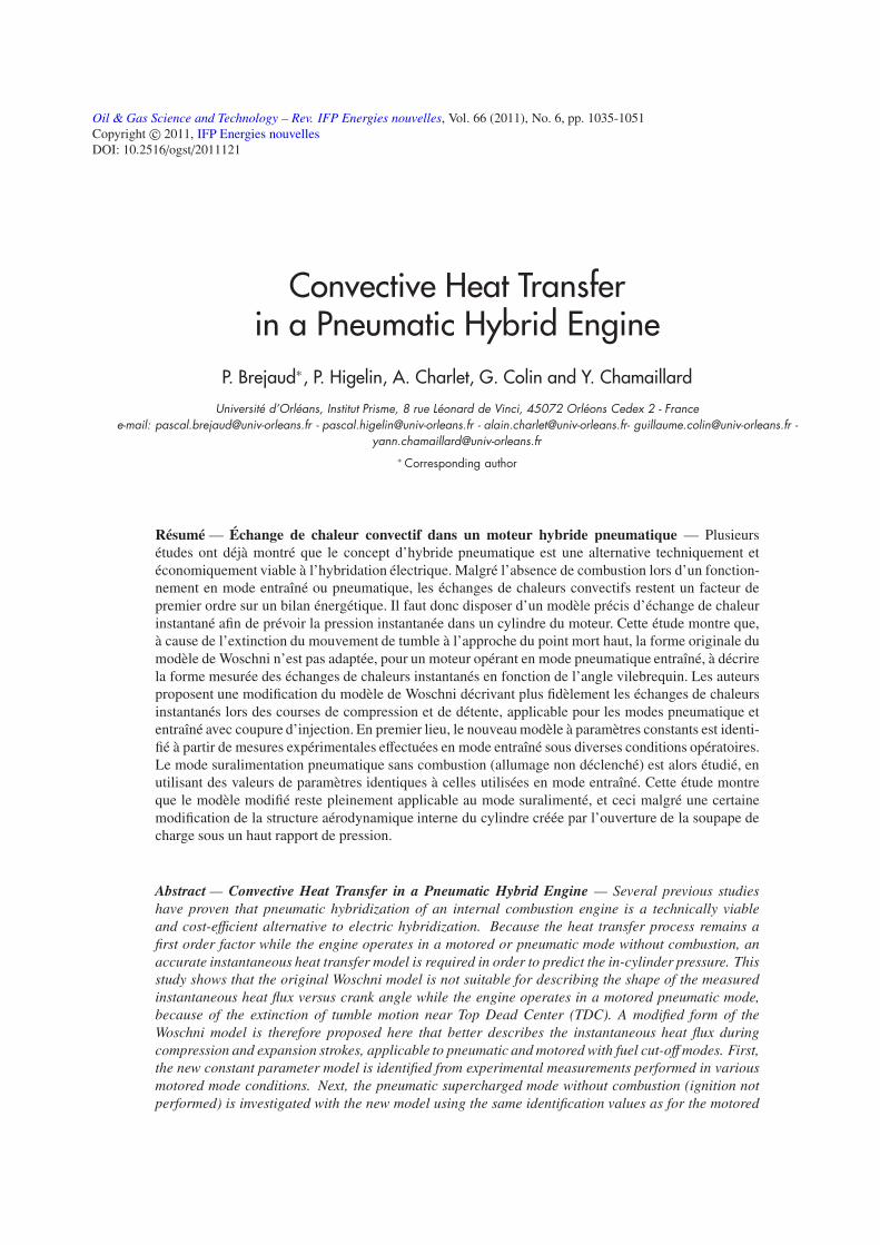
Figure 1
Schematic representation of a single cylinder pneumatic hybridengine.
maximum power and torque leads to increasing engine dis-placement, thus to decreasing mean efficiency at part loadwhich corresponds to real life driving conditions. This draw-back can be tackled by downsizing the engine while keepinga high maximum power with the use of a turbocharger. How-ever, this in turn creates the problem of “turbo-lag’’ during astrong acceleration transient phase. The turbocharger inertialimits its rotational acceleration, and hence the supercharg-ing capacity of the engine.
The second problem is that vehicle braking energy cannotbe transformed back into re-usable energy. This shortcom-ing is tackled with the hybridization concept, such as theelectric hybrid vehicle.
Another alternative is pneumatic hybridization, whichprovides a smart answer to both of the above-mentionedproblems. The concept of the pneumatic hybrid engine,which has been investigated by several research gro-ups [1-6], is based on a conventional internal combustionengine in which one additional valve, called the charg-ing valve, connects the combustion chamber to an airtank as shown Figure 1. Intake and exhaust valves canremain camshaft-driven, and only the charging valve ismoved by a fully variable actuator. As a result, thenew major modes allowed by this additional valve (pneu-matic pump, pneumatic motor and supercharged) remains4-Strokes cycles [7].
Pneumatic Pump: This mode transforms vehicle kineticenergy into a re-usable pneumatic energy. The cyclebegins with a conventional intake stroke. The chargingvalve opens during the compression stroke as soon as
P Brejaud et al. / Convective Heat Transfer in a Pneumatic Hybrid Engine 1037
the in-cylinder pressure reaches that of the charging port.The valve closes shortly after TDC, and the cycle finisheswith conventional expansion and exhaust strokes.
Pneumatic Motor: This mode is used to transform pneu-matic energy into mechanical work without anycombustion. The cycle begins with classical intake andcompression strokes. The charging valve opens whenapproaching TDC, and remains open during part of theexpansion stroke in order to maintain pressure at a highlevel and generate the desired indicated work. The cyclefinishes with a conventional exhaust stroke.
Pneumatic Supercharged Mode: This mode is used to com-pensate for the “turbo lag’’ effect, while temporarilyboost the engine during a strong acceleration transient.The charging valve opens shortly after intake valve clo-sure, and closes when the desired additional air mass hasflowed into the in-cylinder. The end of the cycle remainsthe same as a conventional four stroke one.
Several previous publications [3,7-9] have shown that theconcept of a pneumatic hybrid engine could provide benefitsin terms of fuel consumption and greenhouse gas emissionsthat are comparable with those of an electric hybrid vehi-cle [10], but with lower weight and presumably lower cost.
This paper focuses on a convective heat transfer modelwhile operating in a motored with fuel cut-off or pneumaticmodes for two reasons.
The first is that despite the absence of combustion duringa pneumatic cycle, an energy balance applied to experimen-tal data constantly shows that heat transfer remains a firstorder factor. See Sections 3 and 4. Thus, to accuratelypredict mechanical performances, a heat exchange modelwhich correctly predicts the instantaneous heat transfer isneeded. The main problem is that the in-cylinder aerody-namic structure while operating in pneumatic mode may bevery different from a conventional mode during compressionand expansion strokes (intake and exhaust strokes remainunchanged). Because of the high pressure ratio that existsbetween the pneumatic charging port and the in-cylinder,the opening of the charging valve changes the in-cylinderinternal aerodynamic structure and modifies the convectiveheat transfer process.
The second reason is that the efficiency optimization ofthe pneumatic hybrid requires accurate knowledge of in-cylinder pressure versus Crank Angle, in order to determinethe optimum timings for opening and closure of the charg-ing valve [11]. Thus, the heat transfer model used has toaccurately predict the instantaneous heat transfer flux as afunction of Crank Angle, in order to correctly compute thecylinder pressure that directly determines the optimum tim-ings.
Accordingly, the required heat exchange model mustfirstly predict the total heat exchange during compressionand expansion strokes, and secondly describe as precisely
250 300 350 400 450 500-12 000
-10 000
-8 000
-6 000
-4 000
-2 000
0
Instantaneous heat flux (W)
Crank angle (deg.)
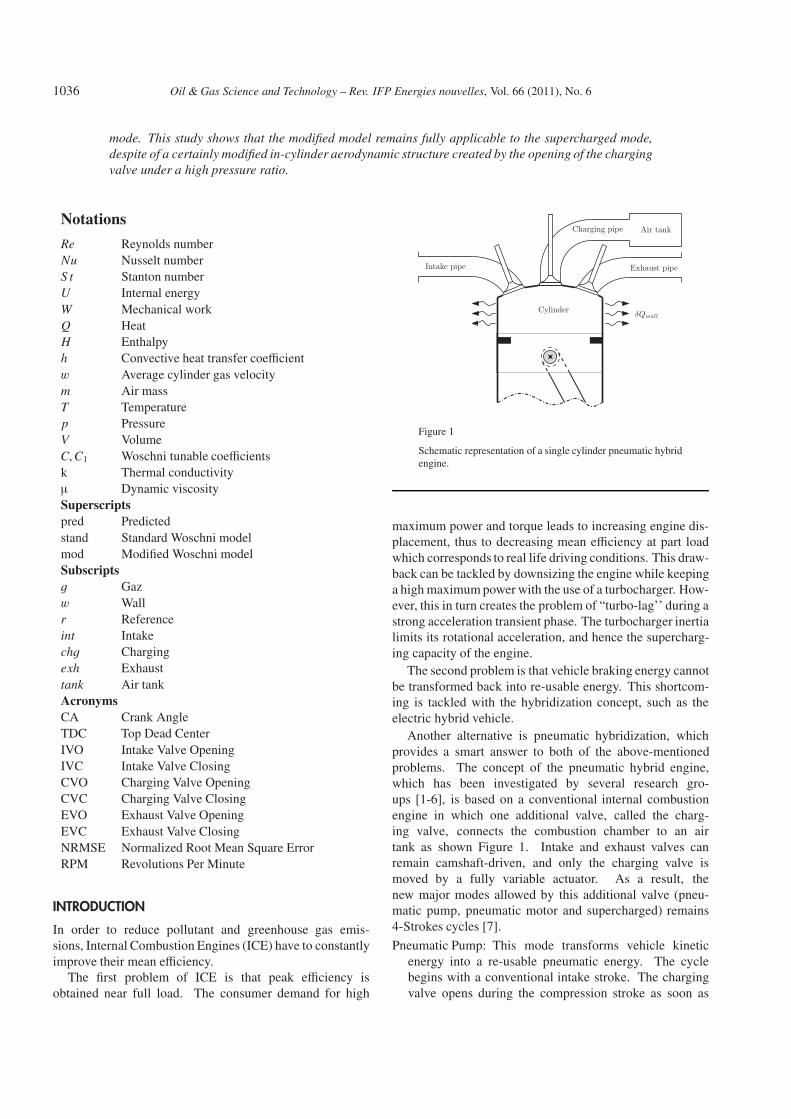
Figure 2
Heat transfer flux obtained during a supercharged mode with-out combustion.
as possible the instantaneous heat flux as function of CrankAngle.
Experimental plots of instantaneous heat transfer fluxversus Crank Angle, for different pneumatic modes andoperating parameters, constantly show an atypical shapecompared to that encountered in the well-known combustionmode. Figure 2 displays such an example for the pneumaticsupercharged mode without combustion (ignition not per-formed). The Crank Angle reference is defined at exhaustTDC. As we shall see, such an asymmetric shape whichis shifted from TDC cannot be predicted by the Woschnimodel in its original formulation. It is therefore necessaryto modify the model, and to verify that the proposed modelremains valid under various operating conditions.
The present work focuses on the motored mode and thesupercharged mode without combustion. Pneumatic pumpand motor modes are not investigated, because of the longduration of the charging valve opening (open thermody-namic system) that does not allow computation of the heattransfer flux during this period.
The paper is organized as follows. First, the classicalcalculations of gas temperature, instantaneous heat trans-fer, and the assumptions made by Woschni to build hisfrequently used correlation are recalled. The heat transferfor several motored engine conditions is then investigated.This study leads us to propose a new form of the correla-tion. Lastly, the supercharged mode is investigated usingthe adapted form of the Woschni model.
1 IN-CYLINDER PRESSURE BASED CALCULATIONOF THE HEAT FLUX AND OF THE HEAT TRANSFERCOEFFICIENT
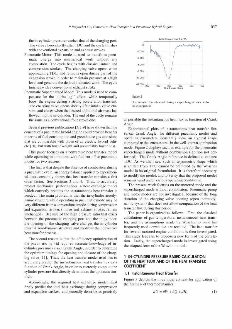
1.1 Instantaneous Heat TransferFigure 3 depicts the in-cylinder context for application ofthe first law of thermodynamics:
dU = δW + δQ + dHi (1)
1038 Oil & Gas Science and Technology – Rev. IFP Energies nouvelles, Vol. 66 (2011), No. 6
dmi
δQ
δW
p, T, m, V
dHi
Figure 3
In-cylinder context for application of the first law of thermo-dynamics.
By rearranging (Eq. 1), using Joule’s law (U = m.cv.T +U∗0)and the ideal gas law, the instantaneous heat transfer flux canbe determined:
δQdt=
1γ − 1
[γp
dVdt+ V
dpdt
]− cpT 0
i
dmi
dt(2)
In the special case where the system is closed (dmi = 0),which is the case if all valves are closed and blow-by gasesare neglected [14], the global heat transfer flux can be sim-ply determined by the in-cylinder pressure measurement.Otherwise, in the case of an open system, the mass flowrate dmi
dt and the stagnation temperature T 0i of flowing gases
have to be known in order to determine the heat transfer rate.
1.2 Heat Transfer Model
Applying the assumption of steady convective heat transfer,the heat flux can be calculated by Newton’s law:
dQ(θ)dt
= h(θ).A [T − Tw] (3)
θ is the Crank Angle. h(θ) is the empirical heat transfercoefficient which is assumed to be the same for the entireheat transfer surface A at the mean temperature Tw. The in-cylinder gas temperature T is determined using the ideal gaslaw:
T =pVmR
(4)
Over the last 50 years, many authors have proposed severalcorrelations to compute h. One family of correlations isbased on a Stanton number correlation [12,13], but the largemajority of available models are based on a Nusselt numbercorrelation [14-17]:
Nu =h.Lc
k(5)
The most commonly used model is that of Woschni [14], andis based on a Nusselt number correlation suitable for forcedconvection in turbulent pipe flow:
Nu = K1Rem (6)
K1 is a tunable coefficient, and a suitable value for m under aforced convection turbulent flow is 0.8. Woschni then intro-duces three correlations for the Reynolds Number, thermalconductivity and dynamic viscosity of the fluid:
Re =1μρwLc (7)
k = K2T 0.75 (8)
μ = K3T 0.62 (9)
Considering the bore d as the characteristic length Lc, re-arrangement of the previous equations gives:
h = C.dm−1 pmwmT 0.75−1.62m (10)
C is the final tunable coefficient, and w is the average cylin-der gas velocity. For a four stroke direct injection CI enginewithout swirl, Woschni proposes:
w = C1V +C2VdTr
prVr(p − pm) (11)
Vd is the displaced volume, p is the instantaneous cylinderpressure, pm is the motored cylinder pressure at same CrankAngle as p. pr, Vr and Tr are respectively the pressure, vol-ume and temperature at a reference point (i.e. intake valveclosing). When combustion does not occur, which is thecase considered here, the C2 coefficient has to be set to zero,and Woschni assumes the cylinder gas velocity w to be con-stant during compression and expansion, and to depend onlyon mean piston speed through the tunable coefficient C1.This strong hypothesis is of course valid only if no swirlor no tumble exists.
2 PNEUMATIC HYBRID ENGINE, INSTRUMENTATIONAND CONTROL
The pneumatic hybrid engine used for experiments is aprototype single cylinder, 347 cm3 displacement, 4-Stroke,Spark-Ignition, indirect fuel injection, with hemisphericalcylinder head and flat piston. Table 1 gives the generalengine dimensions and Table 2 gives the specifications ofthe valves, pipes and actuators. All measurements aretaken in Crank Angle domain (10 samples per CA◦). In-cylinder pressure is measured by a piezoelectric pressuresensor. The intake, charging and exhaust port pressures aremeasured by three absolute piezo-resistive sensors. Intakeair port temperature is measured by a Pt100 sensor, andexhaust and charging port temperatures are measured by two
P Brejaud et al. / Convective Heat Transfer in a Pneumatic Hybrid Engine 1039
K-thermocouples. The intake and charging mass flow ratesare measured with two mass flow controllers. The exhaustpressure is regulated by a valve. The intake and charging aircan be warmed up by two resistive heaters. Two plenumsof around 30 liters volume are mounted on both intake andexhaust lines. Temperature controls are implemented onboth water and oil circuits (80◦C regulated).
TABLE 1
Prototype engine dimension
Bore 79.5 mm
Stroke 70 mm
Connecting rod length 129 mm
Compression ratio 9.1
Air tank volume 50e-3 m3
TABLE 2
Valve and pipe specifications
Intake Exhaust Charging
Number of valve 2 1 1
Valve diameter (mm) 30.35 31.7 12
Actuator Camshaft Camshaft Electric
linear motor
Pipe diameter (mm) 42.4 38 18
Pipe length (mm) 360 1 500 1 200
Valve opening angle (deg) 707 487 fully variable
Valve closing angle (deg) 215 15 fully variable
Maximum lift (mm) 9.21 10 4.8
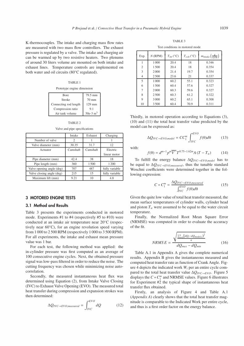
3 MOTORED ENGINE TESTS
3.1 Method and Results
Table 3 presents the experiments conducted in motoredmode. Experiments #1 to #4 (respectively #5 to #10) wereconducted at an intake air temperature near 20◦C (respec-tively near 60◦C), for an engine revolution speed varyingfrom 1 000 to 2 500 RPM (respectively 1 000 to 3 500 RPM).For all experiments, the intake and exhaust mean pressurevalue was 1 bar.
For each test, the following method was applied: thein-cylinder pressure was first computed as an average of100 consecutive engine cycles. Next, the obtained pressuresignal was low-pass filtered in order to reduce the noise. Thecutting frequency was chosen while minimizing noise auto-correlation.
Secondly, the measured instantaneous heat flux wasdetermined using Equation (2), from Intake Valve Closing(IVC) to Exhaust Valve Opening (EVO). The measured totalheat transfer during compression and expansion strokes wasthen determined:
ΔQIVC→EVO,measured =
∫ EVO
IVCdQ (12)
TABLE 3
Test conditions in motored mode
Exp. N (RPM) Tint (◦C) Texh (◦C) mintake
( gcycle
)1 1 000 20.4 18 0.346
2 1 500 20.4 18 0.354
3 2 000 21.4 19.7 0.354
4 2 500 23.6 21 0.337
5 1 000 60.2 55.1 0.323
6 1 500 60.4 57.6 0.327
7 2 000 60.3 59.6 0.327
8 2 500 60.3 61.2 0.322
9 3 000 60.2 65.1 0.308
10 3 500 60.4 70.9 0.311
Thirdly, in motored operation according to Equations (3),(10) and (11) the total heat transfer value predicted by themodel can be expressed as:
ΔQIVC→EVO,model = CCm1
∫ EVO
IVCf (θ)dθ (13)
with:f (θ) = dm−1 pmV
mT 0.75−1.62mA (T − Tw) (14)
To fulfill the energy balance ΔQIVC→EVO,model has tobe equal to ΔQIVC→EVO,measured , thus the tunable standardWoschni coefficients were determined together in the fol-lowing expression:
C ∗ Cm1 =ΔQIVC→EVO,measured∫ EVO
IVCf (θ)dθ
(15)
Given the quite low value of total heat transfer measured, themean surface temperatures of cylinder walls, cylinder headand piston Tw were assumed to be equal to the water circuittemperature.
Finally, the Normalized Root Mean Square Error(NRMSE) was computed in order to evaluate the accuracyof the fit.
NRMS E =
√∑ni=1[dQi−dQmodel,i)2
n
dQmax − dQmin(16)
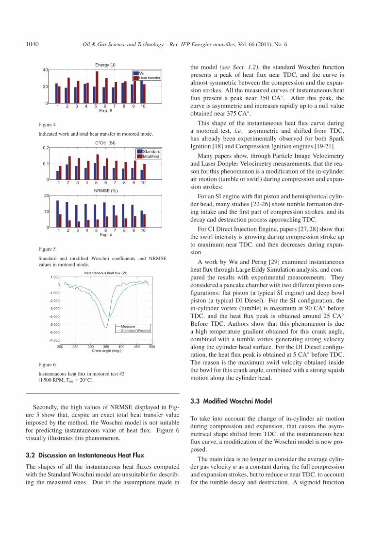
Table A.1 in Appendix A gives the complete numericalresults. Appendix B gives the instantaneous measured andcomputed heat transfer rate as function of Crank Angle. Fig-ure 4 depicts the indicated work Wi per an entire cycle com-pared to the total heat transfer value ΔQIVC→EVO . Figure 5displays the C ∗Cm
1 and NRMSE values. Figure 6 illustratesfor Experiment #2 the typical shape of instantaneous heattransfer flux obtained.
Firstly, an analysis of Figure 4 and Table A.1(Appendix A) clearly shows that the total heat transfer mag-nitude is comparable to the Indicated Work per entire cycle,and thus is a first order factor on the energy balance.
1040 Oil & Gas Science and Technology – Rev. IFP Energies nouvelles, Vol. 66 (2011), No. 6
1 2 3 4 5 6 7 8 9 100
20
40Energy (J)
Exp. #
WiHeat transfer
Figure 4
Indicated work and total heat transfer in motored mode.
1 2 3 4 5 6 7 8 9 100
0.1
0.2C*C 1m (SI)
StandardModified
1 2 3 4 5 6 7 8 9 100
10
20NRMSE (%)
Exp. #
Figure 5
Standard and modified Woschni coefficients and NRMSEvalues in motored mode.
200 250 300 350 400 450 500
-7 000
-6 000
-5 000
-4 000
-3 000
-2 000
-1 000
0
1 000Instantaneous heat flux (W)
Crank angle (deg.)
MeasureStandard Woschni
Figure 6
Instantaneous heat flux in motored test #2(1 500 RPM, Tint = 20◦C).
Secondly, the high values of NRMSE displayed in Fig-ure 5 show that, despite an exact total heat transfer valueimposed by the method, the Woschni model is not suitablefor predicting instantaneous value of heat flux. Figure 6visually illustrates this phenomenon.
3.2 Discussion on Instantaneous Heat Flux
The shapes of all the instantaneous heat fluxes computedwith the Standard Woschni model are unsuitable for describ-ing the measured ones. Due to the assumptions made in
the model (see Sect. 1.2), the standard Woschni functionpresents a peak of heat flux near TDC, and the curve isalmost symmetric between the compression and the expan-sion strokes. All the measured curves of instantaneous heatflux present a peak near 350 CA◦. After this peak, thecurve is asymmetric and increases rapidly up to a null valueobtained near 375 CA◦.
This shape of the instantaneous heat flux curve duringa motored test, i.e. asymmetric and shifted from TDC,has already been experimentally observed for both SparkIgnition [18] and Compression Ignition engines [19-21].
Many papers show, through Particle Image Velocimetryand Laser Doppler Velocimetry measurements, that the rea-son for this phenomenon is a modification of the in-cylinderair motion (tumble or swirl) during compression and expan-sion strokes:
For an SI engine with flat piston and hemispherical cylin-der head, many studies [22-26] show tumble formation dur-ing intake and the first part of compression strokes, and itsdecay and destruction process approaching TDC.
For CI Direct Injection Engine, papers [27, 28] show thatthe swirl intensity is growing during compression stroke upto maximum near TDC. and then decreases during expan-sion.
A work by Wu and Perng [29] examined instantaneousheat flux through Large Eddy Simulation analysis, and com-pared the results with experimental measurements. Theyconsidered a pancake chamber with two different piston con-figurations: flat piston (a typical SI engine) and deep bowlpiston (a typical DI Diesel). For the SI configuration, thein-cylinder vortex (tumble) is maximum at 90 CA◦ beforeTDC. and the heat flux peak is obtained around 25 CA◦Before TDC. Authors show that this phenomenon is duea high temperature gradient obtained for this crank angle,combined with a tumble vortex generating strong velocityalong the cylinder head surface. For the DI Diesel configu-ration, the heat flux peak is obtained at 5 CA◦ before TDC.The reason is the maximum swirl velocity obtained insidethe bowl for this crank angle, combined with a strong squishmotion along the cylinder head.
3.3 Modified Woschni Model
To take into account the change of in-cylinder air motionduring compression and expansion, that causes the asym-metrical shape shifted from TDC. of the instantaneous heatflux curve, a modification of the Woschni model is now pro-posed.
The main idea is no longer to consider the average cylin-der gas velocity w as a constant during the full compressionand expansion strokes, but to reduce w near TDC. to accountfor the tumble decay and destruction. A sigmoid function
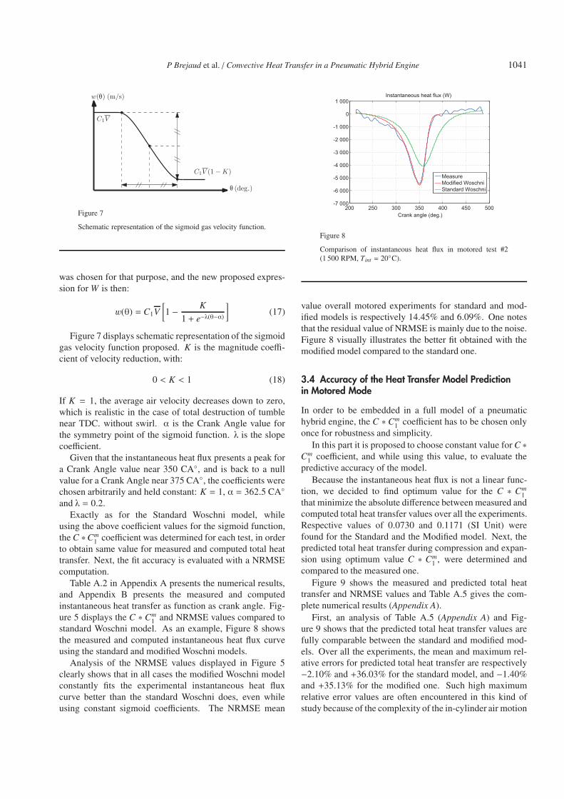
P Brejaud et al. / Convective Heat Transfer in a Pneumatic Hybrid Engine 1041
θ
θ
Figure 7
Schematic representation of the sigmoid gas velocity function.
was chosen for that purpose, and the new proposed expres-sion for W is then:
w(θ) = C1V[1 − K
1 + e−λ(θ−α)
](17)
Figure 7 displays schematic representation of the sigmoidgas velocity function proposed. K is the magnitude coeffi-cient of velocity reduction, with:
0 < K < 1 (18)
If K = 1, the average air velocity decreases down to zero,which is realistic in the case of total destruction of tumblenear TDC. without swirl. α is the Crank Angle value forthe symmetry point of the sigmoid function. λ is the slopecoefficient.
Given that the instantaneous heat flux presents a peak fora Crank Angle value near 350 CA◦, and is back to a nullvalue for a Crank Angle near 375 CA◦, the coefficients werechosen arbitrarily and held constant: K = 1, α = 362.5 CA◦and λ = 0.2.
Exactly as for the Standard Woschni model, whileusing the above coefficient values for the sigmoid function,the C ∗Cm
1 coefficient was determined for each test, in orderto obtain same value for measured and computed total heattransfer. Next, the fit accuracy is evaluated with a NRMSEcomputation.
Table A.2 in Appendix A presents the numerical results,and Appendix B presents the measured and computedinstantaneous heat transfer as function as crank angle. Fig-ure 5 displays the C ∗ Cm
1 and NRMSE values compared tostandard Woschni model. As an example, Figure 8 showsthe measured and computed instantaneous heat flux curveusing the standard and modified Woschni models.
Analysis of the NRMSE values displayed in Figure 5clearly shows that in all cases the modified Woschni modelconstantly fits the experimental instantaneous heat fluxcurve better than the standard Woschni does, even whileusing constant sigmoid coefficients. The NRMSE mean
200 250 300 350 400 450 500-7 000
-6 000
-5 000
-4 000
-3 000
-2 000
-1 000
0
1 000Instantaneous heat flux (W)
Crank angle (deg.)
MeasureModified WoschniStandard Woschni
Figure 8
Comparison of instantaneous heat flux in motored test #2(1 500 RPM, Tint = 20◦C).
value overall motored experiments for standard and mod-ified models is respectively 14.45% and 6.09%. One notesthat the residual value of NRMSE is mainly due to the noise.Figure 8 visually illustrates the better fit obtained with themodified model compared to the standard one.
3.4 Accuracy of the Heat Transfer Model Predictionin Motored Mode
In order to be embedded in a full model of a pneumatichybrid engine, the C ∗ Cm
1 coefficient has to be chosen onlyonce for robustness and simplicity.
In this part it is proposed to choose constant value for C ∗Cm
1 coefficient, and while using this value, to evaluate thepredictive accuracy of the model.
Because the instantaneous heat flux is not a linear func-tion, we decided to find optimum value for the C ∗ Cm
1that minimize the absolute difference between measured andcomputed total heat transfer values over all the experiments.Respective values of 0.0730 and 0.1171 (SI Unit) werefound for the Standard and the Modified model. Next, thepredicted total heat transfer during compression and expan-sion using optimum value C ∗ Cm
1 , were determined andcompared to the measured one.
Figure 9 shows the measured and predicted total heattransfer and NRMSE values and Table A.5 gives the com-plete numerical results (Appendix A).
First, an analysis of Table A.5 (Appendix A) and Fig-ure 9 shows that the predicted total heat transfer values arefully comparable between the standard and modified mod-els. Over all the experiments, the mean and maximum rel-ative errors for predicted total heat transfer are respectively−2.10% and +36.03% for the standard model, and −1.40%and +35.13% for the modified one. Such high maximumrelative error values are often encountered in this kind ofstudy because of the complexity of the in-cylinder air motion
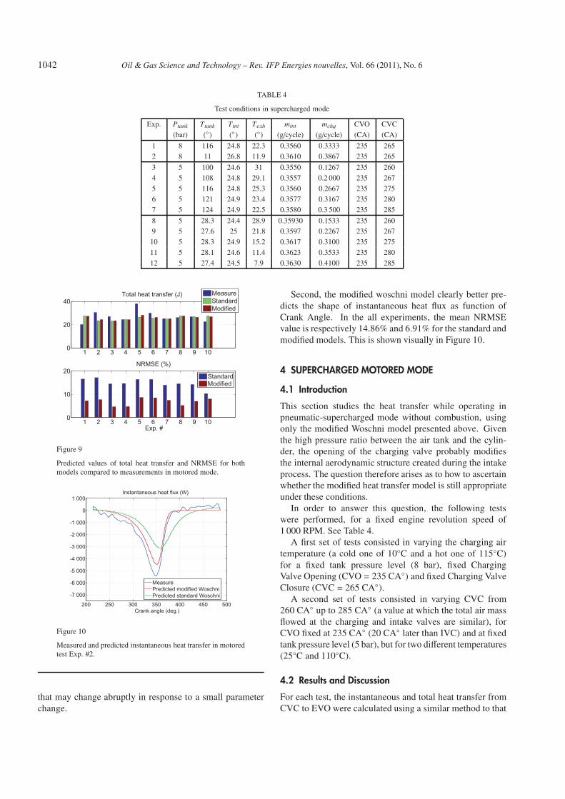
1042 Oil & Gas Science and Technology – Rev. IFP Energies nouvelles, Vol. 66 (2011), No. 6
TABLE 4
Test conditions in supercharged mode
Exp. Ptank Ttank Tint Texh mint mchg CVO CVC
(bar) (◦) (◦) (◦) (g/cycle) (g/cycle) (CA) (CA)
1 8 116 24.8 22.3 0.3560 0.3333 235 265
2 8 11 26.8 11.9 0.3610 0.3867 235 265
3 5 100 24.6 31 0.3550 0.1267 235 260
4 5 108 24.8 29.1 0.3557 0.2 000 235 267
5 5 116 24.8 25.3 0.3560 0.2667 235 275
6 5 121 24.9 23.4 0.3577 0.3167 235 280
7 5 124 24.9 22.5 0.3580 0.3 500 235 285
8 5 28.3 24.4 28.9 0.35930 0.1533 235 260
9 5 27.6 25 21.8 0.3597 0.2267 235 267
10 5 28.3 24.9 15.2 0.3617 0.3100 235 275
11 5 28.1 24.6 11.4 0.3623 0.3533 235 280
12 5 27.4 24.5 7.9 0.3630 0.4100 235 285
1 2 3 4 5 6 7 8 9 100
20
40Total heat transfer (J) Measure
StandardModified
1 2 3 4 5 6 7 8 9 100
10
20NRMSE (%)
Exp. #
StandardModified
Figure 9
Predicted values of total heat transfer and NRMSE for bothmodels compared to measurements in motored mode.
200 250 300 350 400 450 500
-7 000
-6 000
-5 000
-4 000
-3 000
-2 000
-1 000
0
1 000Instantaneous heat flux (W)
Crank angle (deg.)
MeasurePredicted modified WoschniPredicted standard Woschni
Figure 10
Measured and predicted instantaneous heat transfer in motoredtest Exp. #2.
that may change abruptly in response to a small parameterchange.
Second, the modified woschni model clearly better pre-dicts the shape of instantaneous heat flux as function ofCrank Angle. In the all experiments, the mean NRMSEvalue is respectively 14.86% and 6.91% for the standard andmodified models. This is shown visually in Figure 10.
4 SUPERCHARGED MOTORED MODE
4.1 Introduction
This section studies the heat transfer while operating inpneumatic-supercharged mode without combustion, usingonly the modified Woschni model presented above. Giventhe high pressure ratio between the air tank and the cylin-der, the opening of the charging valve probably modifiesthe internal aerodynamic structure created during the intakeprocess. The question therefore arises as to how to ascertainwhether the modified heat transfer model is still appropriateunder these conditions.
In order to answer this question, the following testswere performed, for a fixed engine revolution speed of1 000 RPM. See Table 4.
A first set of tests consisted in varying the charging airtemperature (a cold one of 10◦C and a hot one of 115◦C)for a fixed tank pressure level (8 bar), fixed ChargingValve Opening (CVO = 235 CA◦) and fixed Charging ValveClosure (CVC = 265 CA◦).
A second set of tests consisted in varying CVC from260 CA◦ up to 285 CA◦ (a value at which the total air massflowed at the charging and intake valves are similar), forCVO fixed at 235 CA◦ (20 CA◦ later than IVC) and at fixedtank pressure level (5 bar), but for two different temperatures(25◦C and 110◦C).
4.2 Results and Discussion
For each test, the instantaneous and total heat transfer fromCVC to EVO were calculated using a similar method to that
P Brejaud et al. / Convective Heat Transfer in a Pneumatic Hybrid Engine 1043
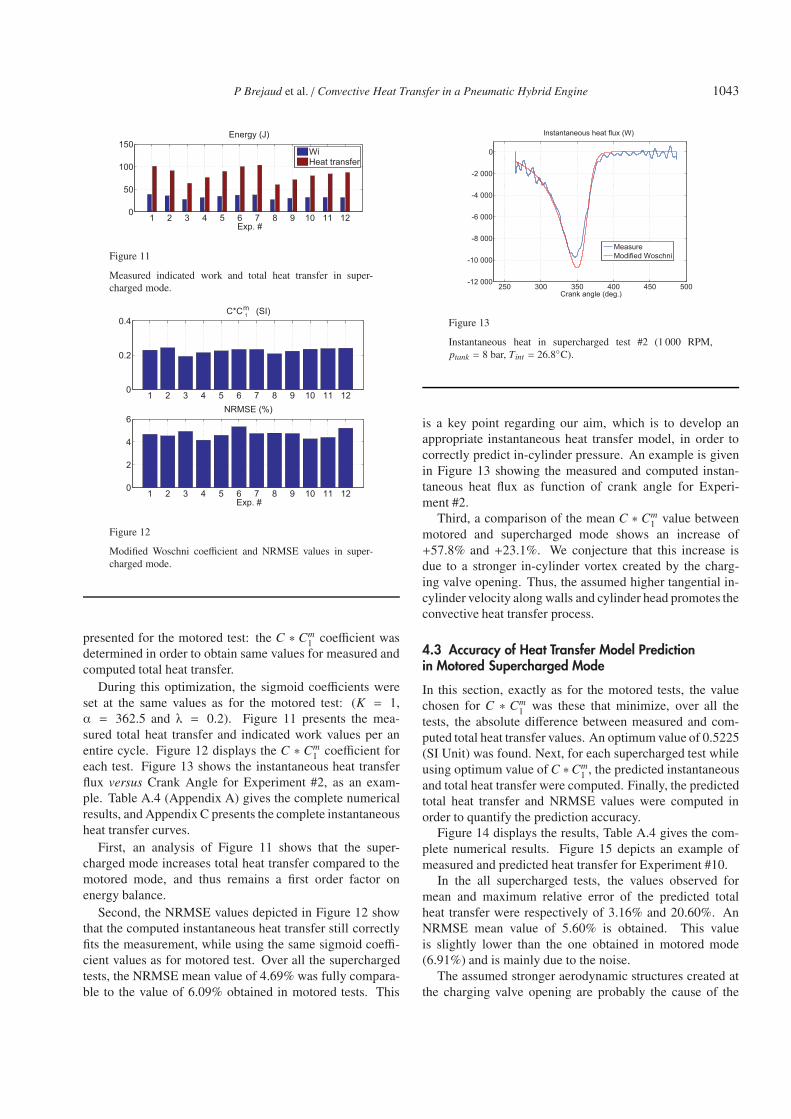
1 2 3 4 5 6 7 8 9 10 11 120
50
100
150Energy (J)
Exp. #
WiHeat transfer
Figure 11
Measured indicated work and total heat transfer in super-charged mode.
1 2 3 4 5 6 7 8 9 10 11 120
0.2
0.4C*C 1
m (SI)
1 2 3 4 5 6 7 8 9 10 11 120
2
4
6NRMSE (%)
Exp. #
Figure 12
Modified Woschni coefficient and NRMSE values in super-charged mode.
presented for the motored test: the C ∗ Cm1 coefficient was
determined in order to obtain same values for measured andcomputed total heat transfer.
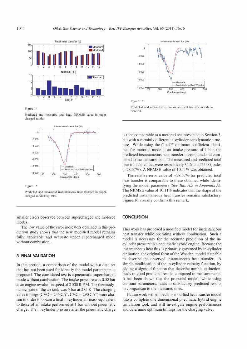
During this optimization, the sigmoid coefficients wereset at the same values as for the motored test: (K = 1,α = 362.5 and λ = 0.2). Figure 11 presents the mea-sured total heat transfer and indicated work values per anentire cycle. Figure 12 displays the C ∗ Cm
1 coefficient foreach test. Figure 13 shows the instantaneous heat transferflux versus Crank Angle for Experiment #2, as an exam-ple. Table A.4 (Appendix A) gives the complete numericalresults, and Appendix C presents the complete instantaneousheat transfer curves.
First, an analysis of Figure 11 shows that the super-charged mode increases total heat transfer compared to themotored mode, and thus remains a first order factor onenergy balance.
Second, the NRMSE values depicted in Figure 12 showthat the computed instantaneous heat transfer still correctlyfits the measurement, while using the same sigmoid coeffi-cient values as for motored test. Over all the superchargedtests, the NRMSE mean value of 4.69% was fully compara-ble to the value of 6.09% obtained in motored tests. This
250 300 350 400 450 500-12 000
-10 000
-8 000
-6 000
-4 000
-2 000
0
Instantaneous heat flux (W)
Crank angle (deg.)
MeasureModified Woschni
Figure 13
Instantaneous heat in supercharged test #2 (1 000 RPM,ptank = 8 bar, Tint = 26.8◦C).
is a key point regarding our aim, which is to develop anappropriate instantaneous heat transfer model, in order tocorrectly predict in-cylinder pressure. An example is givenin Figure 13 showing the measured and computed instan-taneous heat flux as function of crank angle for Experi-ment #2.
Third, a comparison of the mean C ∗ Cm1 value between
motored and supercharged mode shows an increase of+57.8% and +23.1%. We conjecture that this increase isdue to a stronger in-cylinder vortex created by the charg-ing valve opening. Thus, the assumed higher tangential in-cylinder velocity along walls and cylinder head promotes theconvective heat transfer process.
4.3 Accuracy of Heat Transfer Model Predictionin Motored Supercharged Mode
In this section, exactly as for the motored tests, the valuechosen for C ∗ Cm
1 was these that minimize, over all thetests, the absolute difference between measured and com-puted total heat transfer values. An optimum value of 0.5225(SI Unit) was found. Next, for each supercharged test whileusing optimum value of C ∗Cm
1 , the predicted instantaneousand total heat transfer were computed. Finally, the predictedtotal heat transfer and NRMSE values were computed inorder to quantify the prediction accuracy.
Figure 14 displays the results, Table A.4 gives the com-plete numerical results. Figure 15 depicts an example ofmeasured and predicted heat transfer for Experiment #10.
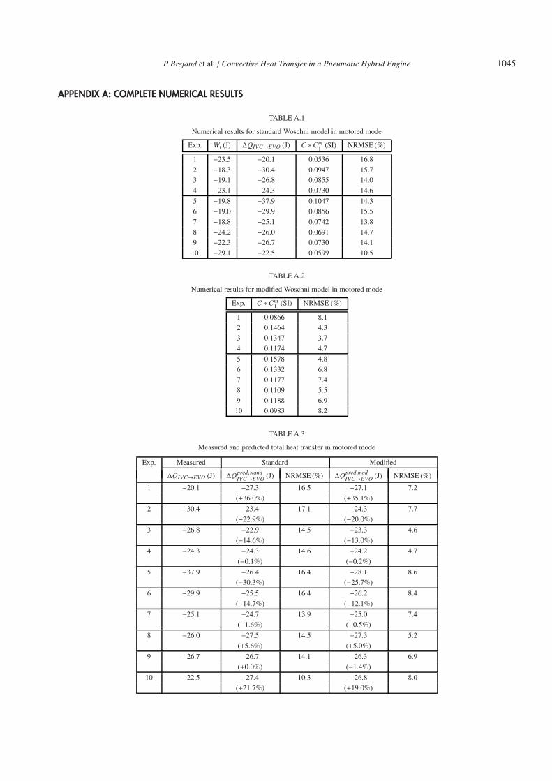
In the all supercharged tests, the values observed formean and maximum relative error of the predicted totalheat transfer were respectively of 3.16% and 20.60%. AnNRMSE mean value of 5.60% is obtained. This valueis slightly lower than the one obtained in motored mode(6.91%) and is mainly due to the noise.
The assumed stronger aerodynamic structures created atthe charging valve opening are probably the cause of the
1044 Oil & Gas Science and Technology – Rev. IFP Energies nouvelles, Vol. 66 (2011), No. 6
1 2 3 4 5 6 7 8 9 10 11 120
50
100
150Total heat transfer (J)
MeasureModified
1 2 3 4 5 6 7 8 9 10 11 120
5
10
15NRMSE (%)
Exp. #
Standard
Figure 14
Predicted and measured total heat, NRMSE value in super-charged mode.
250 300 350 400 450 500-12 000
-10 000
-8 000
-6 000
-4 000
-2 000
0
Instantaneous heat flux (W)
Crank angle (deg.)
MeasurePredicted modified Woschni
Figure 15
Predicted and measured instantaneous heat transfer in super-charged mode Exp. #10.
smaller errors observed between supercharged and motoredmodes.
The low value of the error indicators obtained in this pre-diction study shows that the new modified model remainsfully applicable and accurate under supercharged modewithout combustion.
5 FINAL VALIDATION
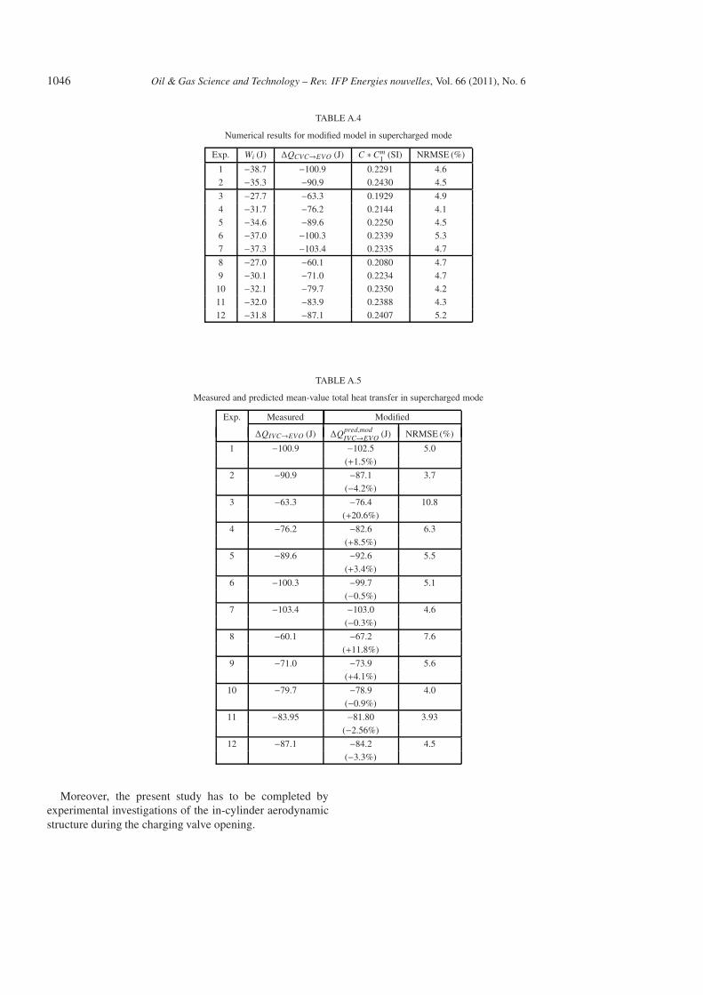
In this section, a comparison of the model with a data setthat has not been used for identify the model parameters isproposed. The considered test is a pneumatic superchargedmode without combustion. The intake pressure was 0.58 barat an engine revolution speed of 2 000 R.P.M. The thermody-namic state of the air tank was 5 bar at 285 K. The chargingvalve timings (CVO = 235 CA◦, CVC = 290 CA◦) were cho-sen in order to obtain a final in-cylinder air mass equivalentto those of an intake performed at 1 bar without pneumaticcharge. The in-cylinder pressure after the pneumatic charge
250 300 350 400 450 500-10 000
-8 000
-6 000
-4 000
-2 000
0
Instantaneous heat flux (W)
Crank angle (deg)
MeasurePredicted modified Woschni
Figure 16
Predicted and measured instantaneous heat transfer in valida-tion test.
is then comparable to a motored test presented in Section 3,but with a certainly different in-cylinder aerodynamic struc-ture. While using the C ∗ Cm
1 optimum coefficient identi-fied for motored mode at an intake pressure of 1 bar, thepredicted instantaneous heat transfer is computed and com-pared to the measurement. The measured and predicted totalheat transfer values were respectively 35.64 and 25.00 joules(−28.57%). A NRMSE value of 10.11% was obtained.
The relative error value of −28.57% for predicted totalheat transfer is comparable to these obtained while identi-fying the model parameters (See Tab. A.5 in Appendix A).The NRMSE value of 10.11% indicates that the shape of thepredicted instantaneous heat transfer remains satisfactory.Figure 16 visually confirms this remark.
CONCLUSION
This work has proposed a modified model for instantaneousheat transfer while operating without combustion. Such amodel is necessary for the accurate prediction of the in-cylinder pressure in a pneumatic hybrid engine. Because theinstantaneous heat flux is primarily governed by in-cylinderair motion, the original form of the Woschni model is unableto describe the observed instantaneous heat transfer. Asimple modification of the in-cylinder velocity function, byadding a sigmoid function that describe tumble extinction,leads to good predicted results compared to measurements.It has been shown that the proposed model, while usingconstant parameters, leads to satisfactory predicted resultsin comparison to the measured ones.
Future work will embed this modified heat transfer modelinto a complete one dimensional pneumatic hybrid enginesimulation tool, and will investigate engine performancesand determine optimum timings for the charging valve.
P Brejaud et al. / Convective Heat Transfer in a Pneumatic Hybrid Engine 1045
APPENDIX A: COMPLETE NUMERICAL RESULTS
TABLE A.1
Numerical results for standard Woschni model in motored mode
Exp. Wi (J) ΔQIVC→EVO (J) C ∗Cm1 (SI) NRMSE (%)
1 −23.5 −20.1 0.0536 16.8
2 −18.3 −30.4 0.0947 15.7
3 −19.1 −26.8 0.0855 14.0
4 −23.1 −24.3 0.0730 14.6
5 −19.8 −37.9 0.1047 14.3
6 −19.0 −29.9 0.0856 15.5
7 −18.8 −25.1 0.0742 13.8
8 −24.2 −26.0 0.0691 14.7
9 −22.3 −26.7 0.0730 14.1
10 −29.1 −22.5 0.0599 10.5
TABLE A.2
Numerical results for modified Woschni model in motored mode
Exp. C ∗Cm1 (SI) NRMSE (%)
1 0.0866 8.1
2 0.1464 4.3
3 0.1347 3.7
4 0.1174 4.7
5 0.1578 4.8
6 0.1332 6.8
7 0.1177 7.4
8 0.1109 5.5
9 0.1188 6.9
10 0.0983 8.2
TABLE A.3
Measured and predicted total heat transfer in motored mode
1046 Oil & Gas Science and Technology – Rev. IFP Energies nouvelles, Vol. 66 (2011), No. 6
TABLE A.4
Numerical results for modified model in supercharged mode
Exp. Wi (J) ΔQCVC→EVO (J) C ∗Cm1 (SI) NRMSE (%)
1 −38.7 −100.9 0.2291 4.6
2 −35.3 −90.9 0.2430 4.5
3 −27.7 −63.3 0.1929 4.9
4 −31.7 −76.2 0.2144 4.1
5 −34.6 −89.6 0.2250 4.5
6 −37.0 −100.3 0.2339 5.3
7 −37.3 −103.4 0.2335 4.7
8 −27.0 −60.1 0.2080 4.7
9 −30.1 −71.0 0.2234 4.7
10 −32.1 −79.7 0.2350 4.2
11 −32.0 −83.9 0.2388 4.3
12 −31.8 −87.1 0.2407 5.2
TABLE A.5
Measured and predicted mean-value total heat transfer in supercharged mode
Exp. Measured Modified
ΔQIVC→EVO (J) ΔQpred,modIVC→EVO (J) NRMSE (%)
1 −100.9 −102.5 5.0
(+1.5%)
2 −90.9 −87.1 3.7
(−4.2%)
3 −63.3 −76.4 10.8
(+20.6%)
4 −76.2 −82.6 6.3
(+8.5%)
5 −89.6 −92.6 5.5
(+3.4%)
6 −100.3 −99.7 5.1
(−0.5%)
7 −103.4 −103.0 4.6
(−0.3%)
8 −60.1 −67.2 7.6
(+11.8%)
9 −71.0 −73.9 5.6(+4.1%)
10 −79.7 −78.9 4.0
(−0.9%)
11 −83.95 −81.80 3.93
(−2.56%)
12 −87.1 −84.2 4.5
(−3.3%)
Moreover, the present study has to be completed byexperimental investigations of the in-cylinder aerodynamicstructure during the charging valve opening.
P Brejaud et al. / Convective Heat Transfer in a Pneumatic Hybrid Engine 1047
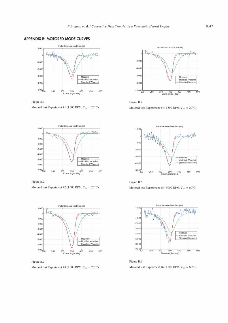
APPENDIX B: MOTORED MODE CURVES
200 250 300 350 400 450 500-5 000
-4 000
-3 000
-2 000
-1 000
0
1 000Instantaneous heat flux (W)
Crank angle (deg.)
MeasureModified WoschniStandard Woschni
Figure B.1
Motored test Experiment #1 (1 000 RPM, Tint = 20◦C).
200 250 300 350 400 450 500-7 000
-6 000
-5 000
-4 000
-3 000
-2 000
-1 000
0
1 000Instantaneous heat flux (W)
Crank angle (deg.)
MeasureModified WoschniStandard Woschni
Figure B.2
Motored test Experiment #2 (1 500 RPM, Tint = 20◦C).
200 250 300 350 400 450 500-7 000
-6 000
-5 000
-4 000
-3 000
-2 000
-1 000
0
1 000Instantaneous heat flux (W)
Crank angle (deg.)
MeasureModified WoschniStandard Woschni
Figure B.3
Motored test Experiment #3 (2 000 RPM, Tint = 20◦C).
200 250 300 350 400 450 500-10 000
-8 000
-6 000
-4 000
-2 000
0
Instantaneous heat flux (W)
Crank angle (deg.)
MeasureModified WoschniStandard Woschni
Figure B.4
Motored test Experiment #4 (2 500 RPM, Tint = 20◦C).
200 250 300 350 400 450 500-5 000
-4 000
-3 000
-2 000
-1 000
0
1 000Instantaneous heat flux (W)
Crank angle (deg.)
MeasureModified WoschniStandard Woschni
Figure B.5
Motored test Experiment #5 (1 000 RPM, Tint = 60◦C).
200 250 300 350 400 450 500-7 000
-6 000
-5 000
-4 000
-3 000
-2 000
-1 000
0
1 000Instantaneous heat flux (W)
Crank angle (deg.)
MeasureModified WoschniStandard Woschni
Figure B.6
Motored test Experiment #6 (1 500 RPM, Tint = 60◦C).
1048 Oil & Gas Science and Technology – Rev. IFP Energies nouvelles, Vol. 66 (2011), No. 6
200 250 300 350 400 450 500-7 000
-6 000
-5 000
-4 000
-3 000
-2 000
-1 000
0
1 000Instantaneous heat flux (W)
Crank angle (deg.)
MeasureModified WoschniStandard Woschni
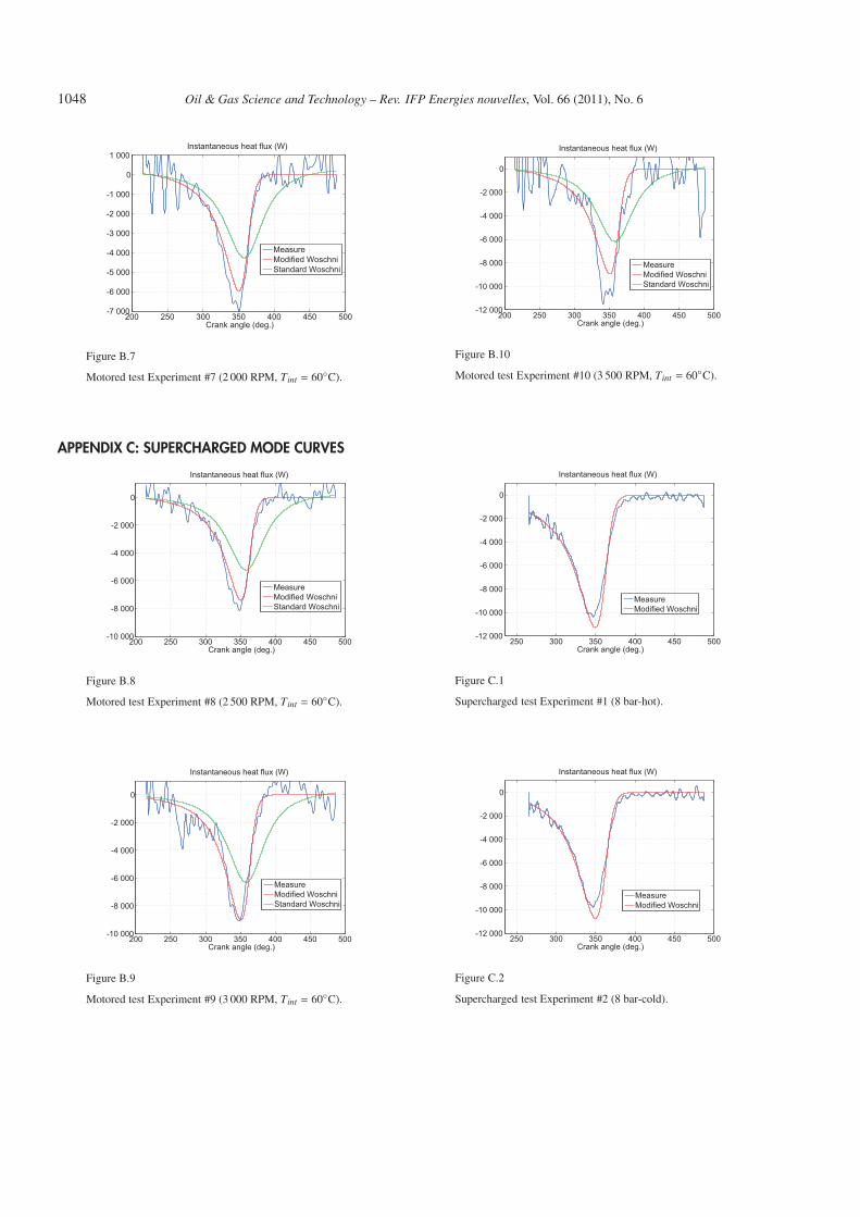
Figure B.7
Motored test Experiment #7 (2 000 RPM, Tint = 60◦C).
APPENDIX C: SUPERCHARGED MODE CURVES
200 250 300 350 400 450 500-10 000
-8 000
-6 000
-4 000
-2 000
0
Instantaneous heat flux (W)
Crank angle (deg.)
MeasureModified WoschniStandard Woschni
Figure B.8
Motored test Experiment #8 (2 500 RPM, Tint = 60◦C).
200 250 300 350 400 450 500-10 000
-8 000
-6 000
-4 000
-2 000
0
Instantaneous heat flux (W)
Crank angle (deg.)
MeasureModified WoschniStandard Woschni
Figure B.9
Motored test Experiment #9 (3 000 RPM, Tint = 60◦C).
200 250 300 350 400 450 500-12 000
-10 000
-8 000
-6 000
-4 000
-2 000
0
Instantaneous heat flux (W)
Crank angle (deg.)
MeasureModified WoschniStandard Woschni
Figure B.10
Motored test Experiment #10 (3 500 RPM, Tint = 60◦C).
250 300 350 400 450 500-12 000
-10 000
-8 000
-6 000
-4 000
-2 000
0
Instantaneous heat flux (W)
Crank angle (deg.)
MeasureModified Woschni
Figure C.1
Supercharged test Experiment #1 (8 bar-hot).
250 300 350 400 450 500-12 000
-10 000
-8 000
-6 000
-4 000
-2 000
0
Instantaneous heat flux (W)
Crank angle (deg.)
MeasureModified Woschni
Figure C.2
Supercharged test Experiment #2 (8 bar-cold).
P Brejaud et al. / Convective Heat Transfer in a Pneumatic Hybrid Engine 1049
250 300 350 400 450 500-12 000
-10 000
-8 000
-6 000
-4 000
-2 000
0
Instantaneous Heat Flux (W)
Crank angle (deg.)
MeasureModified Woschni
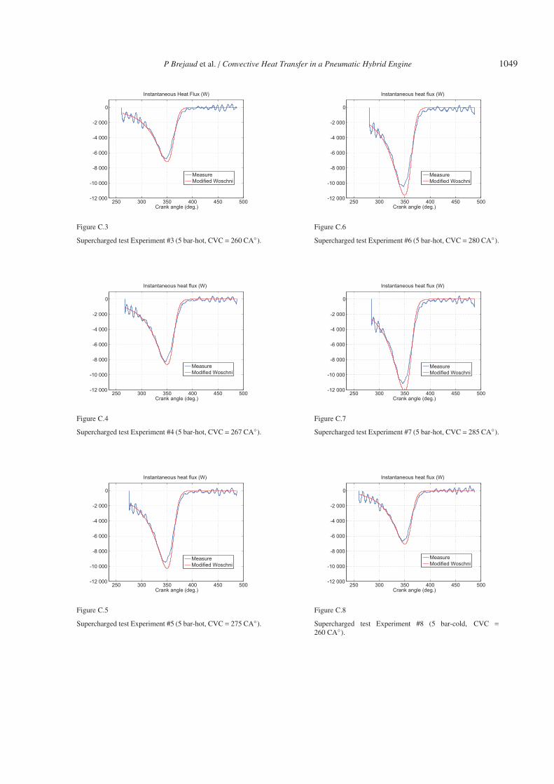
Figure C.3
Supercharged test Experiment #3 (5 bar-hot, CVC = 260 CA◦).
250 300 350 400 450 500-12 000
-10 000
-8 000
-6 000
-4 000
-2 000
0
Instantaneous heat flux (W)
Crank angle (deg.)
MeasureModified Woschni
Figure C.4
Supercharged test Experiment #4 (5 bar-hot, CVC = 267 CA◦).
250 300 350 400 450 500-12 000
-10 000
-8 000
-6 000
-4 000
-2 000
0
Instantaneous heat flux (W)
Crank angle (deg.)
MeasureModified Woschni
Figure C.5
Supercharged test Experiment #5 (5 bar-hot, CVC = 275 CA◦).
250 300 350 400 450 500-12 000
-10 000
-8 000
-6 000
-4 000
-2 000
0
Instantaneous heat flux (W)
Crank angle (deg.)
MeasureModified Woschni
Figure C.6
Supercharged test Experiment #6 (5 bar-hot, CVC = 280 CA◦).
250 300 350 400 450 500-12 000
-10 000
-8 000
-6 000
-4 000
-2 000
0
Instantaneous heat flux (W)
Crank angle (deg.)
MeasureModified Woschni
Figure C.7
Supercharged test Experiment #7 (5 bar-hot, CVC = 285 CA◦).
250 300 350 400 450 500-12 000
-10 000
-8 000
-6 000
-4 000
-2 000
0
Instantaneous heat flux (W)
Crank angle (deg.)
MeasureModified Woschni
Figure C.8
Supercharged test Experiment #8 (5 bar-cold, CVC =
260 CA◦).
1050 Oil & Gas Science and Technology – Rev. IFP Energies nouvelles, Vol. 66 (2011), No. 6
250 300 350 400 450 500-12 000
-10 000
-8 000
-6 000
-4 000
-2 000
0
Instantaneous heat flux (W)
Crank angle (deg.)
MeasureModified Woschni
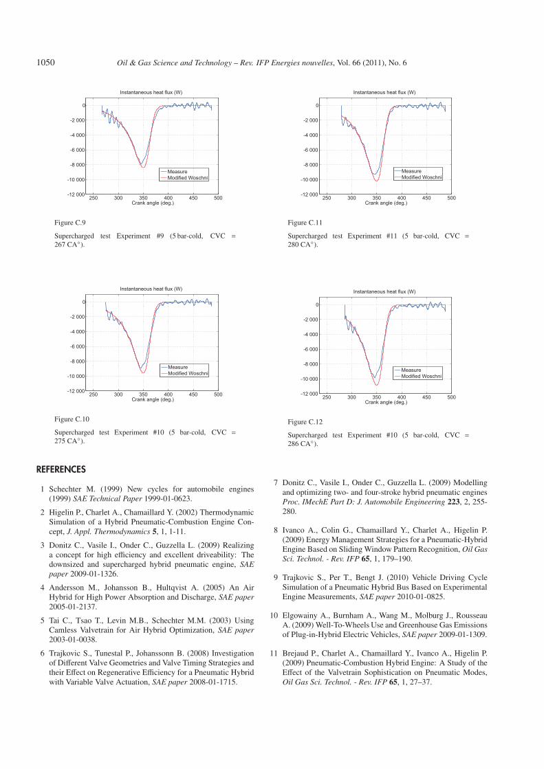
Figure C.9
Supercharged test Experiment #9 (5 bar-cold, CVC =
267 CA◦).
250 300 350 400 450 500-12 000
-10 000
-8 000
-6 000
-4 000
-2 000
0
Instantaneous heat flux (W)
Crank angle (deg.)
MeasureModified Woschni
Figure C.10
Supercharged test Experiment #10 (5 bar-cold, CVC =
275 CA◦).
REFERENCES
1 Schechter M. (1999) New cycles for automobile engines(1999) SAE Technical Paper 1999-01-0623.
2 Higelin P., Charlet A., Chamaillard Y. (2002) ThermodynamicSimulation of a Hybrid Pneumatic-Combustion Engine Con-cept, J. Appl. Thermodynamics 5, 1, 1-11.
3 Donitz C., Vasile I., Onder C., Guzzella L. (2009) Realizinga concept for high efficiency and excellent driveability: Thedownsized and supercharged hybrid pneumatic engine, SAEpaper 2009-01-1326.
4 Andersson M., Johansson B., Hultqvist A. (2005) An AirHybrid for High Power Absorption and Discharge, SAE paper2005-01-2137.
5 Tai C., Tsao T., Levin M.B., Schechter M.M. (2003) UsingCamless Valvetrain for Air Hybrid Optimization, SAE paper2003-01-0038.
6 Trajkovic S., Tunestal P., Johanssonn B. (2008) Investigationof Different Valve Geometries and Valve Timing Strategies andtheir Effect on Regenerative Efficiency for a Pneumatic Hybridwith Variable Valve Actuation, SAE paper 2008-01-1715.
250 300 350 400 450 500-12 000
-10 000
-8 000
-6 000
-4 000
-2 000
0
Instantaneous heat flux (W)
Crank angle (deg.)
MeasureModified Woschni
Figure C.11
Supercharged test Experiment #11 (5 bar-cold, CVC =
280 CA◦).
250 300 350 400 450 500-12 000
-10 000
-8 000
-6 000
-4 000
-2 000
0
Instantaneous heat flux (W)
Crank angle (deg.)
MeasureModified Woschni
Figure C.12
Supercharged test Experiment #10 (5 bar-cold, CVC =
286 CA◦).
7 Donitz C., Vasile I., Onder C., Guzzella L. (2009) Modellingand optimizing two- and four-stroke hybrid pneumatic enginesProc. IMechE Part D: J. Automobile Engineering 223, 2, 255-280.
8 Ivanco A., Colin G., Chamaillard Y., Charlet A., Higelin P.(2009) Energy Management Strategies for a Pneumatic-HybridEngine Based on Sliding Window Pattern Recognition, Oil GasSci. Technol. - Rev. IFP 65, 1, 179–190.
9 Trajkovic S., Per T., Bengt J. (2010) Vehicle Driving CycleSimulation of a Pneumatic Hybrid Bus Based on ExperimentalEngine Measurements, SAE paper 2010-01-0825.
10 Elgowainy A., Burnham A., Wang M., Molburg J., RousseauA. (2009) Well-To-Wheels Use and Greenhouse Gas Emissionsof Plug-in-Hybrid Electric Vehicles, SAE paper 2009-01-1309.
11 Brejaud P., Charlet A., Chamaillard Y., Ivanco A., Higelin P.(2009) Pneumatic-Combustion Hybrid Engine: A Study of theEffect of the Valvetrain Sophistication on Pneumatic Modes,Oil Gas Sci. Technol. - Rev. IFP 65, 1, 27–37.
P Brejaud et al. / Convective Heat Transfer in a Pneumatic Hybrid Engine 1051
12 Wu Y.Y., Chen B.C., Hsieh F.C., Ke C.T. (2009) Heat transfermodel for small-scale spark-ignition engines, Int. J. Heat MassTrans. 52, 7-8, 1875-1886.
13 Thombare D.G., Verma S.K. (2008) Technological develop-ment in the Stirling cycle engines, Renew. Sust. Energ. Rev.12, 1, 1-38.
14 Woshni G.A. (1967) Universally application equation forinstantaneous heat transfer coefficient in internal combustionengine, SAE 76, 670931, 3065-3083.
15 Annand W.J.D. (1963) Heat transfer in the cylinders of recip-rocating internal combustion engines, Proc. IMechE Part E: J.Process Mechanical Engineering 177, 973-990.
16 Eichelberg G. (1939) Some new investigations on old combus-tion engine problems, Engineering 148, 446-463; Engineering148, 547-560.
21 Sanli A., Ozsezen A.N., Kilicaslan I., Canakci M. (2007) Theinfluence of engine speed and load on the heat transfer betweengases and in-cylinder walls at fired and motored conditions ofan IDI diesel engine, Appl. Therm. Eng. 28, 11-12, 1395-1404.
22 Li Y., Zhao H., Peng Z., Ladommatos N. (2001) Analysis oftumble and swirl motions in a Four-Valve SI Engine (2001),SAE Technical paper 2001-01-3555.
23 Arcoumanis C., Bae C.S., Hu Z. (1994) Flow and combustionin a Four-Valve Spark Ignitin Optical Engine, SAE Technicalpaper 940475.
24 Kang K.Y., Baek J.H. (1995) LDV measurement and analysisof tumble formation and decay in a four-valve engine, Exper.Therm. Fluid Sci. 11, 2, 181-189.
25 Huang R.F., Yang H.S., Yeh C.-N. (2008) In-cylinder flowsof a motored four-stroke engine with flat-crown and slightlyconcave-crown pistons, Exper. Therm. Fluid Sci. 32, 5, 1156-1167.
26 Huang R.F., Huang C.W., Chang S.B., Yang H.S., Lin T.W.,Hsu W.Y. (2005) Topological flow evolutions in cylinder ofa motored engine during intake and compression strokes, J.Fluids Struct. 20, 1, 105-127.
27 Lin L., Shulin D., Jin X., Jinxiang W., Xiaohong G. (2000)Effetcs of combustion chamber geometry on in-cylinder airmotion and performance in DI Diesel Engine, SAE Technicalpaper 2000-01-0510.
28 Kawashima J.I., Ogawa H., Tsuru Y. (1998) Research on a vari-able swirl Intake port for 4-valve Hi-speed DI Diesel Engines,SAE Technical paper 982680.
29 Wu H.W., Perng S.W. (2002) LES analysis of turbulent flowand heat transfer in motored engines with various SGS models,Int. J. Heat Mass Trans. 45, 11, 2315-2328.
Final manuscript received in March 2011Published online in September 2011